EP0439290A1 - Recording and reproducing apparatus - Google Patents
Recording and reproducing apparatus Download PDFInfo
- Publication number
- EP0439290A1 EP0439290A1 EP91300392A EP91300392A EP0439290A1 EP 0439290 A1 EP0439290 A1 EP 0439290A1 EP 91300392 A EP91300392 A EP 91300392A EP 91300392 A EP91300392 A EP 91300392A EP 0439290 A1 EP0439290 A1 EP 0439290A1
- Authority
- EP
- European Patent Office
- Prior art keywords
- recording
- recorded
- program
- information
- management data
- Prior art date
- Legal status (The legal status is an assumption and is not a legal conclusion. Google has not performed a legal analysis and makes no representation as to the accuracy of the status listed.)
- Granted
Links
- 230000005764 inhibitory process Effects 0.000 claims abstract description 75
- 230000009471 action Effects 0.000 claims description 72
- 230000014509 gene expression Effects 0.000 claims description 18
- 230000002452 interceptive effect Effects 0.000 claims description 11
- 230000002401 inhibitory effect Effects 0.000 claims description 9
- 230000001747 exhibiting effect Effects 0.000 claims description 5
- 230000033001 locomotion Effects 0.000 description 128
- 238000000034 method Methods 0.000 description 92
- 238000012545 processing Methods 0.000 description 82
- 230000008569 process Effects 0.000 description 65
- 230000006870 function Effects 0.000 description 15
- 230000004048 modification Effects 0.000 description 11
- 238000012986 modification Methods 0.000 description 11
- 230000003449 preventive effect Effects 0.000 description 10
- 238000010276 construction Methods 0.000 description 8
- 238000010586 diagram Methods 0.000 description 8
- 238000012790 confirmation Methods 0.000 description 7
- 210000003128 head Anatomy 0.000 description 6
- 230000010365 information processing Effects 0.000 description 6
- 230000007246 mechanism Effects 0.000 description 6
- 230000005540 biological transmission Effects 0.000 description 5
- 210000004709 eyebrow Anatomy 0.000 description 5
- 206010048232 Yawning Diseases 0.000 description 4
- 230000004397 blinking Effects 0.000 description 4
- 230000000694 effects Effects 0.000 description 4
- 230000007958 sleep Effects 0.000 description 4
- 230000005236 sound signal Effects 0.000 description 4
- 101000930348 Homo sapiens Protein dispatched homolog 2 Proteins 0.000 description 3
- 102100035637 Protein dispatched homolog 2 Human genes 0.000 description 3
- 230000005856 abnormality Effects 0.000 description 3
- 238000013473 artificial intelligence Methods 0.000 description 3
- 230000002093 peripheral effect Effects 0.000 description 3
- 230000004044 response Effects 0.000 description 3
- 102100022907 Acrosin-binding protein Human genes 0.000 description 2
- 102100038445 Claudin-2 Human genes 0.000 description 2
- 241000989913 Gunnera petaloidea Species 0.000 description 2
- 101000882901 Homo sapiens Claudin-2 Proteins 0.000 description 2
- 101000930354 Homo sapiens Protein dispatched homolog 1 Proteins 0.000 description 2
- 101000930501 Homo sapiens Protein dispatched homolog 3 Proteins 0.000 description 2
- 102100022465 Methanethiol oxidase Human genes 0.000 description 2
- 101710134383 Methanethiol oxidase Proteins 0.000 description 2
- 102100035622 Protein dispatched homolog 1 Human genes 0.000 description 2
- 102100035625 Protein dispatched homolog 3 Human genes 0.000 description 2
- 102100037344 Serglycin Human genes 0.000 description 2
- 102100040791 Zona pellucida-binding protein 1 Human genes 0.000 description 2
- 230000008859 change Effects 0.000 description 2
- 230000002950 deficient Effects 0.000 description 2
- 230000036961 partial effect Effects 0.000 description 2
- 230000001360 synchronised effect Effects 0.000 description 2
- 230000000007 visual effect Effects 0.000 description 2
- 101100478064 Dictyostelium discoideum pspB gene Proteins 0.000 description 1
- 101000756551 Homo sapiens Acrosin-binding protein Proteins 0.000 description 1
- 102100030383 Phospholipid phosphatase-related protein type 3 Human genes 0.000 description 1
- 102100030368 Phospholipid phosphatase-related protein type 4 Human genes 0.000 description 1
- 102100031798 Protein eva-1 homolog A Human genes 0.000 description 1
- 206010041349 Somnolence Diseases 0.000 description 1
- 101100310674 Tenebrio molitor SP23 gene Proteins 0.000 description 1
- 230000002159 abnormal effect Effects 0.000 description 1
- 230000003044 adaptive effect Effects 0.000 description 1
- 239000002390 adhesive tape Substances 0.000 description 1
- 230000006399 behavior Effects 0.000 description 1
- 238000005452 bending Methods 0.000 description 1
- 238000004891 communication Methods 0.000 description 1
- 230000000193 eyeblink Effects 0.000 description 1
- 210000000887 face Anatomy 0.000 description 1
- 230000008921 facial expression Effects 0.000 description 1
- 210000001624 hip Anatomy 0.000 description 1
- 238000003780 insertion Methods 0.000 description 1
- 230000037431 insertion Effects 0.000 description 1
- 230000003993 interaction Effects 0.000 description 1
- 239000004973 liquid crystal related substance Substances 0.000 description 1
- 238000011017 operating method Methods 0.000 description 1
- 238000002360 preparation method Methods 0.000 description 1
- 230000002265 prevention Effects 0.000 description 1
- 239000012925 reference material Substances 0.000 description 1
- 230000001172 regenerating effect Effects 0.000 description 1
- 230000000717 retained effect Effects 0.000 description 1
- 230000000630 rising effect Effects 0.000 description 1
- 235000019553 satiation Nutrition 0.000 description 1
Images


Classifications
-
- H—ELECTRICITY
- H04—ELECTRIC COMMUNICATION TECHNIQUE
- H04N—PICTORIAL COMMUNICATION, e.g. TELEVISION
- H04N5/00—Details of television systems
- H04N5/76—Television signal recording
- H04N5/78—Television signal recording using magnetic recording
- H04N5/782—Television signal recording using magnetic recording on tape
-
- G—PHYSICS
- G11—INFORMATION STORAGE
- G11B—INFORMATION STORAGE BASED ON RELATIVE MOVEMENT BETWEEN RECORD CARRIER AND TRANSDUCER
- G11B15/00—Driving, starting or stopping record carriers of filamentary or web form; Driving both such record carriers and heads; Guiding such record carriers or containers therefor; Control thereof; Control of operating function
- G11B15/02—Control of operating function, e.g. switching from recording to reproducing
- G11B15/026—Control of operating function, e.g. switching from recording to reproducing by using processor, e.g. microcomputer
-
- G—PHYSICS
- G11—INFORMATION STORAGE
- G11B—INFORMATION STORAGE BASED ON RELATIVE MOVEMENT BETWEEN RECORD CARRIER AND TRANSDUCER
- G11B15/00—Driving, starting or stopping record carriers of filamentary or web form; Driving both such record carriers and heads; Guiding such record carriers or containers therefor; Control thereof; Control of operating function
- G11B15/02—Control of operating function, e.g. switching from recording to reproducing
- G11B15/04—Preventing, inhibiting, or warning against accidental erasing or double recording
-
- G—PHYSICS
- G11—INFORMATION STORAGE
- G11B—INFORMATION STORAGE BASED ON RELATIVE MOVEMENT BETWEEN RECORD CARRIER AND TRANSDUCER
- G11B20/00—Signal processing not specific to the method of recording or reproducing; Circuits therefor
- G11B20/00086—Circuits for prevention of unauthorised reproduction or copying, e.g. piracy
-
- G—PHYSICS
- G11—INFORMATION STORAGE
- G11B—INFORMATION STORAGE BASED ON RELATIVE MOVEMENT BETWEEN RECORD CARRIER AND TRANSDUCER
- G11B23/00—Record carriers not specific to the method of recording or reproducing; Accessories, e.g. containers, specially adapted for co-operation with the recording or reproducing apparatus ; Intermediate mediums; Apparatus or processes specially adapted for their manufacture
- G11B23/28—Indicating or preventing prior or unauthorised use, e.g. cassettes with sealing or locking means, write-protect devices for discs
-
- G—PHYSICS
- G11—INFORMATION STORAGE
- G11B—INFORMATION STORAGE BASED ON RELATIVE MOVEMENT BETWEEN RECORD CARRIER AND TRANSDUCER
- G11B27/00—Editing; Indexing; Addressing; Timing or synchronising; Monitoring; Measuring tape travel
- G11B27/02—Editing, e.g. varying the order of information signals recorded on, or reproduced from, record carriers
- G11B27/031—Electronic editing of digitised analogue information signals, e.g. audio or video signals
- G11B27/032—Electronic editing of digitised analogue information signals, e.g. audio or video signals on tapes
-
- G—PHYSICS
- G11—INFORMATION STORAGE
- G11B—INFORMATION STORAGE BASED ON RELATIVE MOVEMENT BETWEEN RECORD CARRIER AND TRANSDUCER
- G11B27/00—Editing; Indexing; Addressing; Timing or synchronising; Monitoring; Measuring tape travel
- G11B27/02—Editing, e.g. varying the order of information signals recorded on, or reproduced from, record carriers
- G11B27/031—Electronic editing of digitised analogue information signals, e.g. audio or video signals
- G11B27/036—Insert-editing
-
- G—PHYSICS
- G11—INFORMATION STORAGE
- G11B—INFORMATION STORAGE BASED ON RELATIVE MOVEMENT BETWEEN RECORD CARRIER AND TRANSDUCER
- G11B27/00—Editing; Indexing; Addressing; Timing or synchronising; Monitoring; Measuring tape travel
- G11B27/10—Indexing; Addressing; Timing or synchronising; Measuring tape travel
- G11B27/102—Programmed access in sequence to addressed parts of tracks of operating record carriers
- G11B27/107—Programmed access in sequence to addressed parts of tracks of operating record carriers of operating tapes
-
- G—PHYSICS
- G11—INFORMATION STORAGE
- G11B—INFORMATION STORAGE BASED ON RELATIVE MOVEMENT BETWEEN RECORD CARRIER AND TRANSDUCER
- G11B27/00—Editing; Indexing; Addressing; Timing or synchronising; Monitoring; Measuring tape travel
- G11B27/10—Indexing; Addressing; Timing or synchronising; Measuring tape travel
- G11B27/19—Indexing; Addressing; Timing or synchronising; Measuring tape travel by using information detectable on the record carrier
- G11B27/28—Indexing; Addressing; Timing or synchronising; Measuring tape travel by using information detectable on the record carrier by using information signals recorded by the same method as the main recording
- G11B27/32—Indexing; Addressing; Timing or synchronising; Measuring tape travel by using information detectable on the record carrier by using information signals recorded by the same method as the main recording on separate auxiliary tracks of the same or an auxiliary record carrier
- G11B27/322—Indexing; Addressing; Timing or synchronising; Measuring tape travel by using information detectable on the record carrier by using information signals recorded by the same method as the main recording on separate auxiliary tracks of the same or an auxiliary record carrier used signal is digitally coded
- G11B27/324—Duty cycle modulation of control pulses, e.g. VHS-CTL-coding systems, RAPID-time code, VASS- or VISS-cue signals
-
- G—PHYSICS
- G11—INFORMATION STORAGE
- G11B—INFORMATION STORAGE BASED ON RELATIVE MOVEMENT BETWEEN RECORD CARRIER AND TRANSDUCER
- G11B27/00—Editing; Indexing; Addressing; Timing or synchronising; Monitoring; Measuring tape travel
- G11B27/10—Indexing; Addressing; Timing or synchronising; Measuring tape travel
- G11B27/19—Indexing; Addressing; Timing or synchronising; Measuring tape travel by using information detectable on the record carrier
- G11B27/28—Indexing; Addressing; Timing or synchronising; Measuring tape travel by using information detectable on the record carrier by using information signals recorded by the same method as the main recording
- G11B27/32—Indexing; Addressing; Timing or synchronising; Measuring tape travel by using information detectable on the record carrier by using information signals recorded by the same method as the main recording on separate auxiliary tracks of the same or an auxiliary record carrier
- G11B27/327—Table of contents
- G11B27/328—Table of contents on a tape [TTOC]
-
- G—PHYSICS
- G11—INFORMATION STORAGE
- G11B—INFORMATION STORAGE BASED ON RELATIVE MOVEMENT BETWEEN RECORD CARRIER AND TRANSDUCER
- G11B27/00—Editing; Indexing; Addressing; Timing or synchronising; Monitoring; Measuring tape travel
- G11B27/10—Indexing; Addressing; Timing or synchronising; Measuring tape travel
- G11B27/34—Indicating arrangements
-
- G—PHYSICS
- G11—INFORMATION STORAGE
- G11B—INFORMATION STORAGE BASED ON RELATIVE MOVEMENT BETWEEN RECORD CARRIER AND TRANSDUCER
- G11B27/00—Editing; Indexing; Addressing; Timing or synchronising; Monitoring; Measuring tape travel
- G11B27/36—Monitoring, i.e. supervising the progress of recording or reproducing
-
- G—PHYSICS
- G11—INFORMATION STORAGE
- G11B—INFORMATION STORAGE BASED ON RELATIVE MOVEMENT BETWEEN RECORD CARRIER AND TRANSDUCER
- G11B31/00—Arrangements for the associated working of recording or reproducing apparatus with related apparatus
-
- H—ELECTRICITY
- H04—ELECTRIC COMMUNICATION TECHNIQUE
- H04N—PICTORIAL COMMUNICATION, e.g. TELEVISION
- H04N5/00—Details of television systems
- H04N5/76—Television signal recording
- H04N5/91—Television signal processing therefor
- H04N5/92—Transformation of the television signal for recording, e.g. modulation, frequency changing; Inverse transformation for playback
- H04N5/9201—Transformation of the television signal for recording, e.g. modulation, frequency changing; Inverse transformation for playback involving the multiplexing of an additional signal and the video signal
- H04N5/9206—Transformation of the television signal for recording, e.g. modulation, frequency changing; Inverse transformation for playback involving the multiplexing of an additional signal and the video signal the additional signal being a character code signal
-
- G—PHYSICS
- G11—INFORMATION STORAGE
- G11B—INFORMATION STORAGE BASED ON RELATIVE MOVEMENT BETWEEN RECORD CARRIER AND TRANSDUCER
- G11B2220/00—Record carriers by type
- G11B2220/90—Tape-like record carriers
-
- G—PHYSICS
- G11—INFORMATION STORAGE
- G11B—INFORMATION STORAGE BASED ON RELATIVE MOVEMENT BETWEEN RECORD CARRIER AND TRANSDUCER
- G11B2220/00—Record carriers by type
- G11B2220/90—Tape-like record carriers
- G11B2220/91—Helical scan format, wherein tracks are slightly tilted with respect to tape direction, e.g. VHS, DAT, DVC, AIT or exabyte
Definitions
- This invention relates to a recording and reproducing apparatus, and more particularly to a recording and reproducing apparatus for application to electronic devices for a consumer use such as a video tape recorder (VTR) for recording and reproducing a program, a so-called radio cassette and the like.
- VTR video tape recorder
- a tape recorder of the above described type is disclosed in United States patent number 4224644.
- a conventional video tape recorder for consumer use.
- a plurality of programs are recorded on a video tape extending in the longitudinal direction of the tape.
- a program head fetching signal is recorded at the top position of each program.
- the video tape recorder is temporarily set in a search mode. The video tape is quickly fed to a position in which the program head fetching signal can be regenerated. Thereafter, the video tape recorder is temporarily changed over to the reproducing mode, thus confirming whether or not the program is the one the user wants to watch.
- a mis-erasing preventive (write-protection) pawl is provided on the casing of the video cassette. Erasure prevention is effected by breaking off this pawl; its absence is detected by the VTR and used to inhibit recording.
- a plurality of programs are recorded by reservation on a video tape extending in the longitudinal direction.
- the user sequentially reserves pieces of reservation information on respective programs by utilising an internal tuner and timer. Then, recording proceeds.
- the conventional video tape recorder merely executes relatively simple functions. Therefore, a conventional information recording and reproducing apparatus could not execute the following elaborate control processes over the external units. The same apparatus could not record a picture in a reserved recording mode while interlocking with external units consisting of a variety of picture sources such as tuners, video tape recorders and the like for a desired period according to requirements. Besides, this prior are apparatus could not cause one or a plurality of video tape recorders to effect dubbing of regenerative video signals and monitors to display the pictures.
- this type of electronic device for a consumer use eg, a video tape recorder
- a video tape recorder is contrived as follows.
- One or a plurality of programs that the user wants to record are reserve-recorded by use of a program timer.
- Higher functions are executable by employing the information registered by reservation.
- the multi-functionalised electronic device for consumer use presents the following problems.
- the user In order to execute a multiplicity of operation modes without causing any error, the user is required to input proper instructive information at a time adaptive to an operating status of the electronic device.
- a monitor display screen may be used as a means for inputting the information. Displayed on the display screen are interactive display elements such as messages or the like for presenting an input operation performed by the user.
- An effective method is, it can be considered, to guide the user's operating procedures in accordance with the operating statuses of the electronic device in a man-machine interactive mode.
- a recording and reproducing apparatus for use with: a recording medium formed with a recording track; and a management database recording region, provided in said recording track, on which management data is recorded, said management data being used to manage programs recorded on said recording track, information of said recording medium, erase permission information or erase inhibition information being recorded in said management database recording region, the apparatus being provided with means operative whereby said program on said recording medium is erased or inhibited from being erased based on said erase permission information or said erase inhibiting information.
- a representation element EYE OP or EYE CL can be displayed based on the reproducing information B3. It is possible to confirm whether or not each recorded program was reproduced in the past by a simple method of discerning the representation element EYE OP or EYE CL . This method does not require troublesome operations to make sure the contents of each recorded program by reproducing it.
- a second aspect of the invention provides a recording and reproducing apparatus for use with: a recording medium formed with a recording track; and a management database recording region, provided in said recording track, on which management data is recorded, said management data being used to manage programs recorded on said recording track, program information corresponding to each of said programs recorded in said recording track of said recording medium, erase permission information or erase inhibition information being recorded in said management database recorded region, the apparatus being provided with means whereby said corresponding program is erased or inhibited from being erased based on said erase permission information or said erase inhibition information.
- the erase permission or erase inhibiting of each of a plurality of program D1-D4 recorded on the recording medium 36 is specified by recording the erase permission/.inhibition information as program information in the management data recording region F AVV or F AVA .
- the program information is read therefrom, whereby the an erase inhibition program can be prevented from being erased.
- a third aspect of the invention provides a recording and reproducing apparatus for use with: a recording medium formed with a recording track; and a management database recording region, provided in said recording track, on which management data is recorded, said management data being used to manage a program recorded on said recording track, information indicating whether or not said program recorded in said recording track was reproduced being recorded as reproducing information of said management data corresponding to said program in said management database recorded region, the apparatus being provided with means for displaying said reproducing information as information of said program.
- recorded in the management data recording region F AVV or F AVA of the recording medium 36 is the information for specifying the erase permission or erase inhibition to the recording medium 36.
- the recording and reproducing apparatus 1 is controlled in the erase permission or inhibition status. The user is thereby allowed to specify the erase permission or erase inhibition according to the necessity when setting the management data D AV after charging the recording medium 36. As a result, operability by the user can be further improved.
- a fourth aspect of the invention provides a recording and reproducing apparatus for use with: a recording medium formed with recording tracks, on which one or a plurality of programs be recorded, a management database region being formed in predetermined positions of said recording tracks; management data corresponding to the program being recorded in said management database region; and external unit control data for controlling a plurality of external units being allocated to said management data; the apparatus being provided with means for controlling said external units in accordance with said external unit control data.
- the external unit control data D CTL stored as the management data D AV can be transmitted as the control signals S30 through S33 to external units 61 through 64.
- the plurality of external units 61 through 64 can thereby be controlled.
- a fifth aspect of the invention provides a recording and reproducing apparatus for use with: a recording medium formed with recording tracks, on which one or a plurality of programs be recorded, a management database recording region being formed in predetermined positions of said recording tracks; and management data corresponding to the program being recorded in said management database recording region; the apparatus being provided with means for writing a recorded flag as the management data to divert record reserving information corresponding to the program to recorded information.
- recorded flag F RE C is recorded as the management data D AV in the management database recording region F AVA , F AVV .
- the program information written as reserving information is diverted to the recorded program information, thereby further simplifying the processes of recording and reserving information.
- a sixth aspect of the invention provides a program reserving apparatus for use with: a recording medium formed with recording tracks; management database recording regions being provided on said recording tracks to record management data corresponding to each program, the apparatus being provided with means for using said management data for displaying a registration status of the program on a display screen, means for allocating subscriber data of the program to said management data corresponding to the program, and means for displaying said registration status of the program based on the subscriber data.
- registration status of the program is displayed on the display screens 4A, 6A in accordance with the subscriber data D PRG .
- the respective subscribers are able to readily confirm the program registration statuses necessary for the individual users. It is therefore feasible to surely grasp the program registration status.
- a seventh aspect of the invention provides an information inputting apparatus for prompting a responsive operation of the user by displaying interactive display elements representing operating conditions of an electronic device body on a display screen comprising: a character display means for displaying a personified guide character exhibiting expressions and actions corresponding to display contents of said interactive display elements in positions corresponding to said interactive display elements on said display screen.
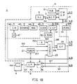
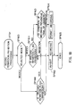
- FIG. 1 illustrates a video tape recorder (VTR) 1 as a whole.
- VTR video tape recorder
- a recording video signal S1 inputted via a video signal processing unit 2 is supplied to a VTR unit 3, thereby recording a picture.
- a reproducing video signal S2 is supplied as a video output signal S3 to a monitor 4 through a video signal processing unit 2.
- a control management data processing unit 5 is provided in addition to the components given above.
- An I/O information signal S4 given from a remote controller 6 is transmitted via a remote control transceiver 7 to a central processing unit (CPU) 8 for processing the control management data.
- a piece of control information S5 is transmitted to a bus 9, thereby controlling circuit elements combined to configure the video signal processing unit 2 and the VTR unit 3.
- the control information S6 is communicated via a bus 10 between the control management data processing CPU 8 and a mechanism control CPU 11 of the VTR unit 3. As a result, there is generated a control signal S7 for mechanism elements of which the video tape recorder unit 3 is composed.
- the video signal processing unit 2 works in the following manner. Inputted via an input selecting circuit 23 to a superimpose fader circuit 24 are a receiving video signal S11 received by a tuner 21, an external line video signal S12 supplied from an input line serving as an external video signal source and an internal synchronous signal S13 generated by an internal synchronous circuit 22. The recording video signal S1 is thus obtained at an output terminal of the superimpose fader circuit 24.
- the recording video signal S1 is supplied via a record switching circuit 31 to a recording circuit 32.
- the recording video signal S1 is recorded on a video tape 36 of a video cassette 35 by use of a magnetic head 34 through a recording mode electromagnetic converting circuit 33.
- the video signal thus recorded on the video tape 36 is picked up by a reproducing circuit 37 sequentially through the reproducing mode magnetic head 34 and the electromagnetic converting circuit 33.
- the video signal is then transmitted as a reproducing video signal S2 via a reproducing switching circuit 38 to the video signal processing unit 2.
- This reproducing video signal S2 is converted into a video output signal S3 by means of a video processing circuit 40 through an output selecting circuit 39.
- the video output signal S3 is displayed on a display screen 4A of a monitor 4.
- Basic data is stored in a ROM-based basic data memory 43 on the basis of the I/O information signal S4 inputted from the remote controller 6 or an input information signal S8 inputted from a VTR keyboard 12.
- Process data is stored in a RAM-based register 44.
- the control management data processing CPU 8 of the control management data processing unit 5 processes the basic and process data in accordance with a clock signal of a clock circuit 45. Pieces of control information S5 and S6 are thereby transmitted to the buses 9 and 10.
- a card reader 46 is connected to the bus 9.
- the control management data processing CPU 8 is capable of taking the basic data read from an IC card 47 by the card reader 46 into a register 44.
- a processed result is obtained by effecting the data processing in the CPU 8.
- the CPU 8 supplies an image display information signal S14 as a part of the control information S5 to a video display processor 41.
- An image display signal S15 read from a video RAM 42 in response to the information signal S14 is supplied to the superimpose fader circuit 24.
- a superimpose output signal S17 is generated by superimposing the display signal S15 on a video signal S16 supplied from the input selection circuit 23.
- the superimpose output signal S17 is supplied via an output selection circuit 39 to an image processing circuit 40.
- a picture is formed by superimposing an image signal consisting of a letter, a character and a line on the video signal. The picture is displayed on the display screen 4A of the monitor 4, thereby giving an interaction to the user.
- the control management data processing CPU 8 supplies the remote controller 6 with the image signal representing the same image as the I/O information signal S4 from the remote control transceiver 7. In consequence of this step, the same image as that displayed on the screen 4A of the monitor 4 is displayed on a display screen 6A of the remote controller 6.
- the CPU 8 records write management data S25 as a part of the control information S5 on video recording tracks of the video tape 36, the data S25 being associated with recording and reproducing operations of the VTR unit 3.
- This recording process is effected sequentially through an image recording encoder 51, the record switching circuit 31, the recording circuit 32 and the electromagnetic converting circuit 33.
- the management data written to the video recording tracks is read via a reproducing switching circuit 38. Subsequently, the management data is, after passing through the electromagnetic converting circuit 33, the reproducing circuit and the reproducing switching circuit 38, taken as readout management data S26 into the CPU 8.
- control management data processing CPU 8 additionally supplies the electromagnetic converting circuit 33 with write management data S27 similar to the data S25 given to the image recording encoder 51 via a audio recording encoder 53.
- the data S27 is recorded on audio recording tracks of the video tape 36 by use of the magnetic head 34.
- the management data recorded on the audio tracks of the video tape 36 is read from the electromagnetic converting circuit 33 through the reproducing mode magnetic head 34 to a audio recording decoder 54.
- the management is taken as readout processing data S28 into the CPU 8.
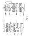
- the control management data processing CPU 8 controls the video tape recorder as a whole in conformity with the function blocks depicted in FIG. 2.
- the CPU 8 when receiving an instruction input from the keyboard 12, functions as an interrupt processing means in a block BK1. Thereafter, the CPU 8 functions as a system schedule/database holding means in a block BK2. At this time, the system schedule/database holding means make communications between itself and a timer reservation database preparing means of a block BK3 while managing a timeseries of the entire system.
- the system schedule/database holding means executes functions as an artificial intelligence module indicated by a block BK4 as well as an application processing means indicated by block BK5.
- the CPU 8 discerns a content of instruction inputted in natural language in accordance with inputting of instruction items expressed in the natural language by a natural language system BK4A.
- a habit of the user is learnt and inferred by a habit learning/inferring system BK4B.
- a habit database is prepared by a habit database preparation system BK4C.
- the CPU 8 cooperates with the module processing means BK5A to execute functions of a management database module BK5B, a user's desire module BK5C, a system set module BK5D and a timer reservation module BK5E.
- the CPU 8 executes a message display process in a message system BK5F.
- the CPU 8 then executes a display process of the monitor 4 in a monitor block BK5G.
- the CPU 8 executes a timer reservation packet process and a flag process in a common data area processing block BK6.
- the means BK5 When effecting the processes in the application processing means BK5, the means BK5 is connected via the I/O driving means BK7 to external units such as the VTR unit 3, the monitor 4, the remote control transceiver 7 and the remote controller 6.
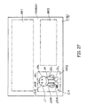
- video recording tracks TA and TB having azimuth angles different from each other are formed in a head scanning direction K1 obliquely across a tape traveling direction K2.
- the recording tracks TA and TB are sequentially adjacent in the tape traveling direction K2.
- a control signal (CTL) recording track TCT is formed in a longitudinal direction of the video tape 36 so that the track TCT is located at an external edge on the extending direction of the video recording tracks TA and TB.
- a control signal CT is recorded on the control signal recording track TCT.
- Two channel audio recording track CH1 and CH2 are formed at an edge of the video tape 36 on the separating direction.
- a management database video track recording region F AVV Formed at the record starting top part of the video tape 36 is a management database video track recording region F AVV extending over predetermined several video recording tracks TA and TB. Subsequent to the management database video track recording region F AVV , a video signal recording region F VD is formed to record 1-field video signal with respect to the respective video recording tracks TA and TB.
- Management data D AV configured as illustrated in FIG. 4 are recorded on the recording tracks TA and TB which belong to the management database video track recording region F AVV .
- a management database audio track recording region F AVA is formed in a predetermined track location, for instance, in the tape top part of the audio recording track CH1 and CH2.
- the management data having a configuration depicted in FIG. 4 is similarly recorded in this region F AVA .
- the management data D AV is arranged so that a volume information block D VM and a program information block D PR are recorded sequentially from the top part of the recording track.
- the volume information block D VM consists of pieces of management information on the video cassette 35 incorporated into the VTR unit 3.
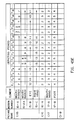
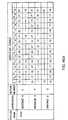
- the volume information block D VM is recorded as pieces of 135-byte volume information containing, as illustrated in FIG. 5, items A1 - A15.
- the information of the item A1 represents a [format version].
- the number of versions of the management data D AV is recorded based on the 1-byte data, thereby identifying the format version concerned when mounting the video cassette 35. With this arrangement, in the case of the management data D AV of even old version, the system is set so that the data can be processed.
- the item A2 represents [the number of repeated recordings].
- the management data D AV is recorded in the management database audio track recording region F AVA in accordance with the 1-byte data. At this time, the number of repeated recordings is recorded.
- the number recordings of the management data D AV by employing the audio signal recording system is recorded as a reference material.
- the item A3 indicates [the number of using pictures].
- the management data D AV on the video cassette 35 in accordance with, e.g., the 1-byte data, the number of recording tracks occupied by a management database video track recording region F AVV is recorded.
- the system discerns a top track location of the video signal recording region F VD .
- the item A4 indicates [the number of used programs].
- T The number of programs reserved or recorded in the video cassette 35 and existence of non-existence of a recording space are recorded on the basis of, e.g., 1-byte data.
- the number of recordable programs reserved or recorded in 0-6 bits is 32 at the maximum.
- the item A5 represents [generation data and time]. Recorded are the data and time when initially writing the management data D AV in the video cassette 35 on the basis of 5-byte data.
- [minute], [hour], [date], [month] and [year] are recorded by binary coded decimal numbers of 2 digits in the first through fifth bytes. Oldness of the video cassette 35 can be known from the volume information D VM of the item representing the data and time of generation.
- the item A6 indicates [update date and time].
- the date and time when modifying the management data D AV on the basis of, e.g., 5-byte data are recorded.
- the data on the update data and time are treated so that [minute], [hour], [date], [month] and [year] are recorded by the binary coded decimal numbers sequentially in the first through fifth bytes. It is thus possible to confirm when the presently used management data D AV is modified.
- the item A7 indicates [system volume number]. If the video cassette 35 is classified as so-called series videos based on, e.g., 8-byte data, the series number concerned is recorded by using the 80byte data. It is therefore feasible to confirm that the video cassette 35 loaded at the present is a kind of series videos as well as to discern the series number thereof. A system volume number is added to the record reservation information held by the VTR unit 3, whereby those matters are displayed on the monitor. The user is thus informed of a video tape 36 which will be reservation-recorded.
- the item A8 represents [screen display color].
- a display color for the list can be specified.
- the item A9 represents [various flags].
- the data on plural kinds of flags can be recorded on the basis of, e.g., 1-byte data.
- the user is allowed to record a flag of [inhibition of recording] in the Oth bit, thereby preserving the recorded contents of the video cassette 35.
- a [formatted] flag can be inputted to the first bit by the system. It is thus possible to confirm whether or not all the recording areas of the video tap 36 are completely formatted.
- An [address mode] flag representing a type of program end address can be inputted to the second and third bits by the system. In consequence of this, even if the program end address is recorded in a mode which differs depending on the video cassette 35, this can surely be detected.
- the item A10 represents a [type of video cassette].
- a length and a type of the tape can be recorded based on, e.g., the 2-byte data.
- the system is capable of automatically setting in the first byte. Whereas in the second byte, the user is able to set as the necessity arises.
- a hub diameter can be recognized by confirming the type and length of the tape.
- the item A11 represents [password].
- the user is allowed to register a password expressed by binary coded decimal numbers of four digits in accordance with, e.g., 2-byte data.
- the user registers the password in the video cassette 35.
- the video cassette 35 is loaded in the VTR unit 3, if the user con not properly input the password registered in the video cassette 35, the recording/reproducing processes of the video cassette 35 are inhibited. This inhibits an observation of contents of the video tape 36.
- the item A12 represents [user volume number].
- the user is allowed to record a video cassette file number, i.e., a volume number on the video cassette 35 as the user desires.
- the volume number can be added by the binary coded decimal numbers within a numeric value range of 0-64000.
- the user volume number is added to the record reservation information held by the VTR unit 3, thereby displaying it on the monitor. With this arrangement, the user can be informed of the video tape 36 which will be recorded by reservation.
- the item A13 represents [reproducing order]. According to the necessity, the reproducing order of 32 programs at the maximum is recordable based on, 32-byte data. In a so-called program reproducing mode, the programs recorded in the order from the first byte to the 32nd byte are sequentially specified. The programs can thus be reproduced.
- the item A14 represents [recording order].
- the serial numbers of the 32 program at the maximum are recordable in 32 recording order positions on the basis of, e.g., the 32-byte data.
- the item A15 represents [volume label].
- the user is allowed to add labels such as a title to the video cassette 35 in accordance with, e.g., 40-byte data as the demands arise.
- a volume label is added to the record reservation information held by the VTR unit 3, thereby displaying it on the monitor. With this arrangement, the user can be informed of the video tape 36 which will be recorded by reservation.
- 40 characters at the maximum are recordable when using ASCII codes.
- labels of 20 characters at the maximum are recordable.
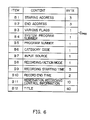
- the program information block D PR is, as illustrated in FIG. 4, composed of program information D PRX shown in FIG. 6, corresponding to the program information recorded or record-reserved on the video tape 36 of the video cassette 35.
- the item B1 represents [starting address].
- the programs are recorded in a video signal recording region F VD of the video cassette 35. Thereafter, in accordance with the [byte] data, a starting address value of each program is written by the system on the basis of the top address of the video tape 36.
- a time mode [second], [minute] and [hour] are expressed by the binary coded decimal numbers
- a program number mode (the program numbers based on the VASS (Video Address Signal Search) (VHS) standard are indicated)
- a control signal mode representation by the number of CTL pulses on the basis of the CTL ( ⁇ ) standard).
- the item B2 represents [end address].
- a program end address value from the top position of the video tape 36 is recorded based on, e.g., the 3 byte data.
- the program end address value is so arranged as to select the time mode, the program number mode and the control signal mode.
- the item B3 represents [various flags].
- a piece of information indicating a handling status of the program information concerned is recorded based on, e.g., the 1-byte data.
- the item B4 represents [system program number] A series of file numbers put on the relevant programs by the system are recorded based on, e.g., the 1-byte data.
- the item B5 represents [program number].
- the user is able to input the number of times of a series program (for instance, a serial drama) in accordance with, e.g., the 1-byte data.
- the item B6 represents [category code]. Categories (for example, sports, news, dramas, etc.) of program contents are recorded based on, e.g., the 1-byte data.
- the item B7 represents [input source].
- An input source indicating where the relevant program is obtained is recorded based on, e.g., the 1-byte data.
- the item B8 represents [recording/action mode].
- An action mode and a recording mode for the video cassette 35 are written based on, e.g., the 1-byte data.
- the recording modes are written.
- the types of [ ⁇ Is mode], [ ⁇ II mode] and [ ⁇ III mode are written.
- the types of [SP system], [LP system] and [EP system] are written.
- the types of [SP mode] and [LP mode] are written.
- action modes during the record the types of for instance, [ordinary recording mode], [only-reference-signal writing mode], etc. are written.
- the item B9 represents [record starting time]. A starting time of the recorded program or reservation is recorded based on, e.g., the 5-byte data.
- [minute], [hour], [date], [month] and [year] are sequentially written to the 1st through 5th bytes by the binary coded decimal numbers.
- the item B10 represents [record end time]. An end time of the recorded program or reservation is recorded based on, e.g., the 2-byte data.
- the [minute] and [time] data are written to the 1st and 2nd bytes by the binary coded decimal numbers.
- the item B11 represents [reservation recording control information]. Reservation recording is set in VTR unit 3 (FIG. 3) in accordanee with, e.g., the 10-byte data when executing reservation recording. Recorded simultaneously is the information for controlling peripheral units to be operated corresponding to the foregoing process.
- the item B12 represents [title].
- the character information indicating a title of the program concerned is written based on, e.g., the 40-byte data.
- the CPU 8 controls the control management data processing unit 5, the video signal processing unit 2 and VTR unit 3. This control process is performed in the status specified by the user in conformity with processing programs RT0, RT1, and RT31 shown in FIGS. 7 through 9.
- the remote controller 6, as illustrated in FIG. 10, has a display screen 6A provided constructed by providing a touch panel on a liquid crystal plate as an operating panel on the case surface.
- the click inputs are effected by touching directly on the respective display items.
- Specifying signals associated with the display items concerned can thus be inputted.
- the cursor displayed on the screen 6A is moved by a 4-directional cursor key 6B, thus specifying a predetermined display item. Thereafter, the specifying signal relative to the display item concerned can be inputted by handling an execution key 6C.
- the remote controller 6 further includes a normal operation instructing key 6D, a menu display instructing key 6E, a management data mode instructing key 6F and reservation 1/reservation 2 operation mode specifying keys 6G and 6H. These mode specifying keys serve to specify the operation modes of the VTR 1 for CPU 8.
- the CPU 8 waits till the power supply is turned ON. If an affirmative result is obtained, the CPU 8 judges whether the power-ON is the first time or not at a step SP2. If that is the first time, the CPU 8 sequentially executes processes of steps SP3, SP4 and SP5. As a result, a message of [time setting will be done] is displayed on a display screen 4A of a monitor 4 as well as on the display screen 6A of the remote controller 6. Subsequent to this step, the present time is set in the system setting operation mode. A message of [time setting has been done] is then displayed on the screens 4A and 6A.
- the VTR 1 is thus brought into an instruction waiting status in which the present time is set.
- This instruction waiting status is retained continuously even when a negative result is obtained at the step SP2.
- the items such as [management database], [system setting], [preference setting] and [timer reservation] can selectively be specified.
- the CPU 8 causes the remote controller 6 (or the keyboard 12) to execute the operation mode specifying display of [management database], [system setting], [preference setting] and [timer reservation] on the display screens 6A and 4A by manipulating the menu display mode specifying key 6E therein. Consequently, the user is able to specify one of the operation modes by the click operation.
- the management data D AV (FIG. 4) is recorded in a management database video track record region F AVV or a management database audio track record region F AVA of the video tape 36 (FIG. 3).
- the CPU 8 judges whether the video cassette 35 is set or not at a step SP7 when the item of [management database] is clicked among the menu display items at the step SP6, the video cassette 35 containing the tape (referred to as a management data tape) on which the management data D AV has been recorded. If set, a variety of processes of the management database are executed in a subroutine RT1.
- the CPU 8 judges whether or not the contents of the management database are modified. If modified, at a step SP9 the CPU 8 executes a process to rewrite, into management data after being modified, the data recorded in the management database video record region F AVV or the management database audio track record region F AVA .
- the CPU 8 judges whether the power supply is turned OFF or not. If the answer is negative, the CPU 8 reverts to the instruction waiting status described above. If affirmative, the input information processing program comes to an end at a step SP11.
- the CPU 8 When entering a multiprocess routine RT1, as illustrated in FIG. 8, at a step SP21 the CPU 8 causes the remote controller 6 and the monitor 4 to display the management database list on the display screens 6A and 4A. After this step, the CPU 8 is brought into the instruction waiting status.
- Displayed at this time on the display screens are items such as [label], [reservation canceling], [auto-reproducing], [manual reserving], [program information confirming] and [management data reserving]. In this state, one of the items can be specified.
- the item [label] herein represents the operation mode in which to selectively set either the volume information or the program information which is contained in the volume information block D VM or the program information block D PR (FIG. 4) among the management data D AV .
- Displayed on the display screens are the items such as [password], [recording mode], [type of tape], [category] and [title], when clicking the item [label] at a step SP22. In this state, one of the items is selectable.
- the CPU 8 permits the user to rewrite the password data recorded in the item A11 of the volume information D VMX (FIG. 5).
- the CPU 8 specifies the record/operation mode recorded in the item B8 of the program information D PRX (FIG. 6). As a result, the record mode data thereof can be written.
- the CPU 8 works to rewrite tape type data among the data indicating type of the video cassette which are recorded in the item A10 of the volume information D VMX (FIG. 5).
- the CPU 8 works to rewrite the category code data recorded in the item B6 of the program information D PRX (FIG. 6).
- the CPU 8 works to rewrite the title data recorded in the item B2 of the program information D PRX (FIG. 6).
- the CPU 8 rewrites the items ranging from [password] to [title] at the steps SP23 through SP27. Subsequent to these steps, when specifying the item [end] at a step SP28, the processes of the management database are finished. From the step SP29 the process returns to the management database processing loop shown in FIG. 7, wherein the process of the step SP8 resumes.
- the CPU 8 cancels the reservations of all the programs recorded in the relevant management data list at a step SP30.
- the CPU 8 When the user clicks the item [auto-reproducing], at a step SP31 the CPU 8 functions to reproduce the reproducing order data of the item A13 of the volume information D VMX (FIG. 5) in the predetermined order and, if necessary, to rewrite the data.
- the CPU 8 sequentially receives manual setting with respect to a predetermined number of programs. Then, the CPU 8 inputs them as management data.
- the CPU 8 After finishing the processes of steps SP30, SP31 and SP32, the CPU 8 reverts to the management database processing loop (FIG. 7), passing through the steps SP28 and SP29.
- the CPU 8 when being in the instruction waiting status for displaying the management data list at the step SP21 of FIG. 8, initiates the process of a step SP33 after the user has clicked the item [program information confirming].
- the representation on the display screen is changed over at a step SP34.
- a step SP35 or SP36 or SP37 or SP38 there comes such a display mode as to confirm or rewrite the recorded contents of the items [record permission], [whether-to-see flag], [category] and [title] of the program information D PRX (FIG. 6) and the volume information D VMX (FIG. 5).
- predetermined pictorial representations i.e., characters are employed as the data of the items [record permission], [whether-to-see flag], [category] and [title]. It is therefore possible to confirm and modify the information recorded in association with a plurality of reserved programs in a relatively narrow display area.
- the CPU 8 After finishing the processes of the steps SP35 to SP38, the CPU 8 returns via the steps SP28 and SP29 to the management database processing loop (FIG. 7).
- the CPU 8 causes the user to select a timer reservation mode at a step SP41.
- a specified item list submittable for causing the user to selectively designate the specified item of the management data.
- Prepared is a language specified item list TBL consisting of language input items in which the specified items are expressed by natural language.
- Prepared also is a graphic specified item list consisting of graphic input items in which the specified items are, as in the ordinary way, expressed by graphic elements such as Roman alphabets, numerals and symbols.
- the CPU 8 causes the user to selectively specify any one of the language input and the graphic input for the reservation screen to be used.
- the CPU 8 moves to a step SP42. Subsequently, the CPU 8 takes, in a register 44, the data corresponding to the language input item specified by the user while displaying the language specified item list TBL on the display screen.
- the CPU 8 moves to a step SP43. Subsequently, the CPU 8 takes, in the register 44, the data corresponding to the graphic input item specified by the user while displaying the graphic specified item list on the display screen.
- the specifying input operation of the user has thus been terminated.
- the CPU 8 finishes the management data reservation input process and reverts to the management database processing loop of FIG. 8.
- the CPU 8 works to subsequently display items such as [registration], [modification] and [reference] on the display screen.
- a calendar reservation table, a one-week reservation table and a one-day reservation table are displayable according to the selection by the user at steps SP54 through SP56.
- a start time or an end time of the program reserved is written in the calendar reservation table or the one-week reservation table or the one-day reservation table.
- the CPU 8 after finishing such processes, terminates the processing program of the management database at the step SP28.
- the CPU 8 returns to the management database processing loop (FIG. 7) from the step SP29.
- the processes discussed above are those to record the management data on the video tape,modify the same data and confirm the same data by clicking the item [management database] at the step SP6.
- the CPU 8 executes a process to set operating conditions of respective units of the VTR 1.
- These items are clicked at steps SP62 through SP69.
- the operating conditions of the individual units of the system can thereby be set.
- the CPU 8 terminates the processes of the system setting processing loop and moves to the above-mentioned step SP10.
- the item [preference setting] is clicked through the CPU 8.
- Displayed on the display screen at this time are items such as [screen display], [management database], [user set], [character], [timer reserving], [user level], [message] and [voice]. These items are clicked at steps SP72 through SP79.
- the CPU 8 executes the process of the respective items concerned. The CPU 8, when finishing the relevant processes, shifts to the above-described step SP10.
- the CPU 8 displays the items [registration], [modification] and [reference] on the display screen.
- the items [calendar reservation table], [one-week reservation table] and [one-day reservation table] are displayed on the display screen.
- the CPU 8 words to display the calendar reservation table, the one-week reservation table or the one-day reservation table at a step SP85, SP86 or SP87.
- the program is then reserved with the aid of the reservation table displayed.
- the CPU 8 after finishing the timer reservation processing loop, moves to the step SP10.
- the CPU 8 executes the input information processing program RT0 of FIG. 7 in the manner. Hence, it is feasible to surely control the VTR unit 3 on the basis of the input data inputted by the user.
- the remote controller 6 or the keyboard 12 is constructed to rewrite [whether-to-see flag information] into an ON state (i.e., logic [1]), this information being provided in each flag of the item B3 of the program information D PRX corresponding to the relevant recorded program.
- a [whether-to-see flag information] confirming procedure RT51 shown in FIG. 12 represents a [whether-to-see flag information] confirming processing in the input information process and the management database setting process of FIGS. 7 and 8.
- Road at a step SP121 is the management data D AV (FIG. 4) recorded in the management database video track recording region F AVV or the management database audio track recording region F AVA of the video tape 36 loaded at the step SP7 of FIG. 7.
- the data D AV is temporarily stored in a register 44 (FIG. 1).
- the process of the step SP36 shown in FIG. 8 is executed.
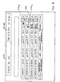
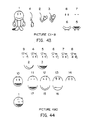
- FIG. 13 illustrates graphic representations HY0 displayed on the display screens 4A and 6A. Displayed at the right end at a step SP124 is a pictorial representation EYE CL depicting an eye closed with respect to a present readout program among the representations HY0.
- the CPU 8 moves to a step SP123 turns ON a [whether-to-see] internal flag (i.e., controls this flag into the [seen] state) incorporated in the VTR unit 3.
- a pictorial representation EYE OP depicting an eye opened is displayed in the display column of the program concerned.
- the user confirms the pictorial representation EYE CL or EYE OP displayed based on [whether-to-see flag information] with respect to the recorded program from the display columns of the respective recorded programs indicated in the graphic representations HY0.
- the user is therefore able to discern whether or not the relevant program was reproduced once in the past.
- the CPU 8 shifts to the step SP28 of FIG. 8. The processing operation comes to an end at a step SP125.
- the first and second registered programs have already been recorded in, e.g., FIG. 12. If the user has seen the contents of the first recorded registered program in the past (i.e., the relevant recorded program was reproduced before), the open-eye pictorial representation EYE OP is displayed in the display column of the first registered program. It is therefore feasible to confirm that the user has seen the contents in the past without performing such a complicated action as to confirm the reproduced contents.
- the eye-closed pictorial representation EYE CL is displayed in the display column of the second recorded registered program. From this representation, the user can make sure that the user did not yet see the second recorded registered program.
- the user is able to discern whether or not the user has seen the contents recorded on the video tape 36 on the display screens 4A of the monitor 4 or and the display screen 6A of the remote controller 6 simply by loading the tape 36 into the VTR unit 3.
- Read is the management data D AV (FIG. 4) recorded in the management database video track recording region F AVV or the management database audio track recording region F AVA of the video tape 36 by virtue of the construction described above.
- the user Based on [whether-to-see flag information] stored in a variety of flags of the item B3 in the management data D AV , the user can discern whether or not the user has seen the relevant recorded program in the past without reproducing the program recorded on the video tape 36.
- This confirmation involves the step of displaying the eye-opened pictorial representation EYE OP or the eye-closed pictorial representation EYE CL of the graphic representations HY0 on the display screen 4A of the monitor 4 or the display screen 6A of the remote controller 6.
- the VTR 1 is constructed described below, adding to the construction of the first embodiment.
- the management data D AV is recorded in the management database audio track recording region F AVA or the management database video track recording region F AVV of the video tape 36.
- Specified to [1] by the user is [record permission flag] corresponding to a predetermined program among [record permission flags] in [various flags] provided in the item B3 of the program information D PRX corresponding to each program of the management data D AV .
- the CPU 8 permits the record of only the program in which [record permission flag] is controlled in the record permission status.
- a record permission/inhibition processing routine RT61 shown in FIG. 14 indicates record permission/inhibition processing operations in the input information process and the management database setting process which are shown in FIGS. 7 and 8.
- the user loads the video cassette 35 in the VTR unit 3 (step SP7 of FIG. 7).
- the CPU 8 sequentially reads pieces of program information D PRX of the respective recorded programs recorded on the video tape 36 from the management data D AV recorded on the video tape 36 of the video cassette 35.
- the CPU 8 judges whether or not [record permission flag] provided in 3rd bit or various flags is in the ON state (i.e., [1] is specified to indicate [record permission status]) with respect to every recorded program by executing the process of the step SP35 shown in FIG. 8.
- the CPU 8 jumps over a step SP133.
- the CPU 8 works to display, in the display column of the relevant recorded program, a pictorial representation REC NO indicating the record inhibition status of a present readout program among graphic representations HY0 of FIG. 13 on the display screens 4A and 6A.
- a program may be newly recorded in the recording region of the recorded program that is now being processed (i.e., this program may be erased).
- the CPU 8 when moving to the next step SP133, changes over a [record permission] internal flag provided in the VTR unit 3 from an initial status, i.e., a [record inhibition] status to a [record permission] status.
- a pictorial representation REC OK indicating a record permission status is displayed in the display column of the relevant program.
- the CPU 8 indicates whether to erase the respective programs recorded in the video tape 36 of the loaded video cassette 35 on the display screens 4A and 6A. At the same moment, the CPU 8 is arranged not to execute the record of a new program even when the user tries to record this new program in the recording region concerned. It is because the [record permission] internal flag corresponding to the relevant recorded program assume the record inhibition status in the recording region of the recorded program undergoing the erase inhibition.
- [record permission flag] corresponding to each of the programs D1 - D4 recorded in a program information block D PR [record permission flags] corresponding to, e.g., the first and second programs D1 and D2 are in the inhibition status.
- the programs D1 and D2 are controlled in the record inhibition status (viz., an erase inhibition status).
- New programs are not recorded in the regions of the programs D1 and D2 recorded in [start addresses] of the program information D PRX corresponding to the programs D1 and D2 on the basis of the start positions of these regions.
- the CPU 8 shifts to a step SP135 to execute the process of the step SP10 of FIG. 7. In consequence of this, the user waists for a take-out instruction of the video cassette 35 or a power-OFF instruction. After executing the instruction, the CPU 8 moves to a subsequent step SP136.
- the management data stored in the register 44 is written to the management database video track recording region F AVV or the management database audio track recording regions F AVA of the video tape 36.
- the CPU 8 executes the take-out action of the video cassette 35 or the power-OFF action in conformity with the user's instruction.
- the record permission/inhibition processing mode is terminated.
- the user is able to confirm the program region in which the program may be erased or should not be erased on the display screens 4A and 6A.
- the new program may be recorded in the erase permission program region alone.
- the management data D AV (FIG. 4) is recorded in the management database video track recording region F AVV or the management database audio track recording region F AVA of the video tape 36.
- the record permission/inhibition (i.e., erase permission/inhibition) information is recorded as the program information in association with every program recorded on the video tape 36.
- the foregoing information is read to visually display the record permission/inhibition region. Simultaneously, the new program can be inhibited from being recorded in the record inhibition region.
- the record (erase) permission or inhibition mode can be specified for each of the plurality of programs recorded on the video tape 36.
- the management data D AV is configured such that the volume information block D VM and the program information block D PR are written sequentially from the top position of the recording track. Instead, however, the block arranging order may be interchanged. A variety modifications may be effected, wherein fine sectioning is done for intermixing as the case may be.
- the embodiment discussed above has dealt with a case where this invention is applied to the VTR. Instead, however, this invention is similarly applicable to other various recording/reproducing apparatuses, wherein an audio signal is recorded as in the way with a so-called radio built-in cassette tape recorder.
- the management data D AV is recorded in the management database audio track recording region F AVA or the management database video track recording region F AVV of the video tape 36.
- the user specifies, in a record inhibition status, [record inhibition flag] among [various flags] provided in the item A9 of the volume information D VMX of the management data D AV .
- the CPU 8 controls the video tape 36 of the video cassette 35 in the erase inhibition status with priority to a condition of the mis-erase preventive pawl provided in the box member of the video cassette 35.
- the CPU 8 for processing the control data detects the condition of the mis-erase preventive pawl of the loaded video cassette 35 with the aid of a mechanism control CPU 11.
- the CPU 8 executes a record permission/inhibition processing routine RT71 shown in FIG. 16. Then, the CPU 8 judges whether the program may be recorded or not.
- the record permission/inhibition processing routine RT71 indicates a record permission/inhibition processing operations in the input information process and the management database setting process which are shown in FIG. 7 and 8.
- the management data D AV recorded on the video tape 36 is read by executing the process of the step SP35 of FIG. 8. There is made a judgement as to whether or not [record inhibition flag] contained in [various flags] is in the inhibition status from the volume information D VMX of the management data D AV .
- step SP141 the CPU 8 controls the VTR unit 3 in the record inhibiting status. Thereafter, the action moves to the step SP28 of FIG. 8, and this processing routine comes to an end at a step SP144.
- step SP140 a status where the program may be newly recorded on the video tape 36 (i.e., the program recorded on the video tape 36 may be erased).
- the CPU 8 shifts to a step SP142.
- the CPU 8 discerns whether a condition of the mis-erase preventive pawl provided in the box member of the video cassette 35 is in the erase inhibition status (viz., the pawl is broken off) or in the erase permission status (i.e., the pawl is unbroken). If turned out to be the erase inhibition status, the CPU 8 shifts to the above-mentioned step SP141 to control the VTR unit 3 in the record inhibition status.
- the CPU 8 shifts to a subsequent step SP143 to control the VTR unit 3 in the record permission status.
- the action moves to the step SP28 of FIG. 8, and the processing operation concerned is terminated at the next step SP144.
- the CPU 8 controls the VTR unit 3 in the record inhibition status irrespective of a condition of the mis-erase preventing pawl provided in the box member of the video cassette 35.
- the CPU 8 executes a record permission/inhibition judgement processing routine RT81 shown in FIG. 17.
- the CPU 8 reads the management data D AV recorded on the video tape 36 of the video cassette 35 loaded into the VTR unit 3.
- the CPU 8 judges whether or not [record inhibition flag] contained in [various flags] assumes an inhibition status from within the volume information D VMX of the management data D AV .
- a [record permission] internal flag of the VTR unit 3 is provided in each program recorded on the video tape 36.
- the CPU 8 changes over this [record permission] internal flag from the [record permission] status defined as an initial status to a [record inhibition] status.
- a pictorial representation showing the record inhibition status is displayed on the display screens 4A and 6A.
- the CPU 8 indicates whether all the programs recorded on the video tape 36 of the loaded video cassette 35 may be erased or not on the display screen 4A and 6A. Even when the user tries to record a new program on the video tape 36, the CPU 8 functions, if erase-inhibited, so as not to execute this action.
- the CPU 8 returns to the step SP140 of the record permission/inhibition processing routine RT71 (FIG. 16) after shifting to a step SP154.
- the user is capable of discerning whether the management data D AV of the video tape 36 of the loaded video cassette 35 assumes the record permission status or the record inhibition status on the display screens 4A and 6A.
- the program can be newly recorded.
- the record inhibition status (i.e., the erase inhibition status) is specified by the management data D AV with the priority to a condition of the mis-erase preventive pawl set in the box member of the video cassette 35.
- the record inhibition can be specified with other operations such as a record reservation. The operability of the user can be further improved, and at the same time the mis-erasing can be prevented with a certainty.
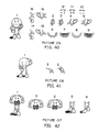
- a record permission/inhibition processing routine RT91 shown in FIG. 18 is executed.
- a processing mode which takes the mis-erase preventive pawl into consideration or a processing mode depending on only a status of the record inhibition flag may be selected.
- the CPU 8 executes the same processes as those of the steps SP140 through SP143 (FIG. 16).
- the CPU 8 thus controls the VTR unit 3 in the record permission or inhibition status.
- the processing routine RT91 is finished.
- the CPU 8 shifts to a step SP166.
- the CPU 8 judges whether or not the record inhibition flag assumes the record inhibition status be executing the same process with the step SP140 (FIG. 16). If an affirmative result is obtained, the CPU 8, after moving to a step SP162, controls the VTR unit 3 in the record inhibition status. Thereafter, the action moves to the step SP28 shown in FIG. 8, and the processing routine RT91 is terminate at a step SP165.
- the CPU 8 After shifting to the step SP164, controls the VTR unit 3 in the record permission status. Then, the action moves to the step SP28 of FIG. 8, and the processing routine RT91 comes to an end at a step SP165.
- the CPU 8 when selecting the processing mode 2, the CPU 8 is capable of controlling the VTR unit 3 in the record permission (i.e., erase permission) or the record inhibition (viz., erase inhibition) depending not on a condition of the mis-erase preventive pawl proceeded in the box member of the video cassette 35 but on only the status of the record inhibition flag. For instance, the mis-erase preventive pawl of the video cassette 35 is broken off, with the result that the cassette 35 is brought into the erase inhibition status. In this case also, the record inhibition flag of the management data D AV recorded on the video tape 36 of the video cassette 35 is changed into the record permission status. In consequence, the program is recordable on the video tape 36.
- the record permission i.e., erase permission
- the record inhibition viz., erase inhibition
- the embodiment discussed above has dealt with a case where a status of the record inhibition flag is visually displayed.
- the present invention is not, however, limited to this visual display.
- the flag status may be indicated by voices or the like.
- the management data D AV is configured such that the volume information block D VM and the program information block D PR are written sequentially from the top position of the recording track. Instead, however, the block arranging order may be interchanged. A variety modifications may be effected, wherein fine sectioning is done for intermixing as the case may be.
- the embodiment discussed above has dealt with a case where this invention is applied to the VTR. Instead, however, this invention is similarly applicable to other various recording/reproducing apparatuses, wherein an audio signal is recorded as in the way with a so-called radio built-in cassette tape recorder.
- the CPU 8 for processing the control management data takes [reserved record control information] into the item B11 (FIG. 6) of the management data D AV with the aid of a user's manual input at the step SP32 of FIG. 8.
- [reserved record control information] is written to the management data D AV of the management database video track recording region F AVV or the management database audio track recording region F AVA of the video tape 36.
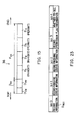
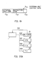
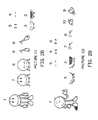
- the external unit control data D CTL indicating [reserved record control information] is, as illustrated in FIG. 19, composed of an external unit code C EX , an instruction code C OP and a transmission code C SD .
- the external unit code C EX consists of code signals for specifying peripheral units connected to the video tape recorder 1.
- the peripheral units include, as illustrated in FIG. 20, e.g., a BS tuner 61, video tape recorders (VTR) 62, 63 and a television receiver (TV) 64.
- the transmission code C SD consists of discerning data for discerning the control for reserved record starting from the control for reproducing.
- the video cassette 35 to which the management data D AV is written is loaded into the video tape recorder unit 3.
- the CPU 8 for processing the control management data of the video tape recorder 1 takes the management data D AV recorded on the video tape 36 into a management data memory of a register 44. This process is performed via a magnetic head 34, an electromagnetic converting circuit 33, a reproducing circuit 37, a reproduction switching circuit 38, an image recording decoder 52 and a bus 9.
- the control management data processing CPU 8 finishes inputting the management data D AV . Based on the management data D AV read from the management data memory of the register 44, a reserved record starting time is read per program. The CPU 8 judges that the present time reaches the reserved record starting time of each program. Based on the external outside unit control data D CTL shown in FIG. 19, the CPU 8 works to transmit the control signals S30 - S33 to the BS tuner 61, the VTRs 62, 63 and the TV 64 which are connected to the video tape recorder 1.
- the external unit control data D CTL is composed of the external unit code C EX , the instruction code C OP and the transmission code C SD .
- the control signals S30 - S33 are transmitted from the video tape recorder 1 when executing the reserved record or effecting the reproduction. With this arrangement, whether the BS tuner 61, the VTRs 62, 63 and the TV 64 are controlled or not is judged.
- the control management data processing CPU 8 fetches plural pieces of external unit control data D CTL corresponding to a first reserved record starting time from the transmission code C SD . Transmitted to the BS tuner 61,the VTRs 62, 63 and the TV 64 are the control signals S30 - S33 composed of the external unit code C EX and the instruction code C OP .
- the BS tuner 61 judges that the external unit code C EX coincides with the intrinsic unit code assigned from the control signal S30 to the BS tuner 61.
- a power supply of the BS tuner 61 is controlled to be turned ON by the instruction code C OP .
- a program is received by setting the receiving channel to, e.g., channel 15.
- the video tape recorder 1 takes in a video signal or external line video signal S12 of the program which is received by the BS tuner 61.
- the video tape recorder 1 (FIG. 1) takes the external line video signal S12 into an input selecting circuit 23.
- the video signal S12 is recorded as a record video signal S1 on the video tape 36 through a superimpose fader circuit 24.
- the CPU 8 fetches the external unit control data D CTL corresponding to the recording time in a second reserved record starting time.
- the control signals S30 - S33 are transmitted to the BS tuner 61, the VTRs 62, 63 and the TV 64.
- the VTRs 62, 63 judge that the external unit codes C EX 1 and C EX2 coincide with the intrinsic unit codes assigned to the VTRs 62, 63 from the control signals S31 and S32.
- the instruction codes C OP and C OP2 function to turn ON a power supply circuit of the VTRs 62, 63.
- the VTRs 62, 63 receive video signals as external line signals S35 and S36 from external input terminals.
- This video signal consists of a receiving video signal S11 inputted via the tuner 21 to the video tape recorder 1 or an external line video signal S12. Recording of the video signals is started in accordance with the instruction codes C OP1 and C OP2 .
- the control management data processing CPU 8 causes the video tape recorder 1 to perform the recording process. Simultaneously, the video signals undergo dubbing by use of the VTRs 62, 63.
- the CPU 8 when reproducing the recorded program, fetches the external unit control data D CTL corresponding to the reproducing time of this program from the management data D AV .
- the control signals S30 - S33 are transmitted to the BS tuner 61, the VTRs 62, 63 and the TV 64.
- the TV 64 judges, as illustrated in FIG. 20C, that the intrinsic unit code of the TV 64 coincides with the external unit code C EX from the control signals S33. Based on the instruction code C OP , a type of surround of the video signal inputted as an external line signal S37 and a volume of surround are controlled.
- a control signal S41 may be, as illustrated in FIG. 21B, taken in parallel. (2-3)
- the embodiment discussed above has dealt with the control to transmit the control signals S30 through S33 consisting of the same information to the BS tuner 61, the VTRs 62, 63 and the TV 64 from the video tape recorder 1.
- the external unit control data D CTL may be, as shown in FIG. 21C, transmitted in a non-contact state from the video tape recorder 1 to an electromagnetic wave W1 or the like.
- a management data mode instruction key 6F of the remote controller 6 (FIG. 10) is switched ON.
- the control management data processing CPU 8 enters a management data D AV readout mode at a step SP90 (FIG. 22).
- the CPU 8 reads the management data D AV into a register 44 from the management database video track recording region F AVV or the management database audio track recording region F AVA formed on the video tape 36.
- This readout process is effected through an electromagnetic converting circuit 33, a reproducing circuit 37, a reproducing switching circuit 38 and an image recording decoder 52.
- a reservation memory incorporated into the video tape recorder unit 3 has stored the same reserving information as that written in [record start time] of the item B9 and [record end time] of the item B10 which constitute program information D PRX (FIG. 6) among the management data D AV read in to the register 44. If the answer is negative, at a step SP93 the reserving information of the register 44 is written as reserved record data to a reservation memory of a mechanism control CPU 11. The action moves to a step SP94.
- control management data processing CPU 8 shifts from the step SP92 directly to a step SP94.
- the CPU 8 works to display pieces of reserving information of, e.g., four registered programs stored in the reservation memory of the CPU 11.
- the reserving information is, as depicted in FIG. 13, graphically displayed in the form of a list HY0 composed of graphic display elements arranged in line per program. A reservation status is thus indicated to the user.
- the present time reaches the record start time written to the register 44.
- the control management data processing CPU 8 executes program recording on the video tape 36 at a step SP95 with the aid of the mechanism control CPU 11. This recording is performed by transmitting control information S6 via a bus 10 to the video tape recorder unit 3. The record of this program is finished. Thereafter, the CPU 8 writes a result that the record concerned is finished normally or an abnormal state appears in first and second bits of [various flags] (FIG. 23) of the item B3 of the management data D AV recorded in the register 44.
- a step SP96 the CPU 8 judges whether or not the record was finished normally from a record end status recorded in the item B3 of the management data D AV . If an abnormality is caused during the record, at a step SP97 the CPU 8 indicates an error message on the display screen 4A of the monitor 4 and the display screen 6A of the remote controller 6. The action the moves to a step SP98.
- the CPU 8 shifts from the step SP96 to the step SP98.
- the reserving information stored in the reservation memory of the CPU 11 is erased.
- 0th bit data representing the recorded flag (FIG. 23) of the item B3 is rewritten from logic [0] data (indicating that the relevant program is now in the reserved status) into logic [1] data (indicating that the relevant program is now in the recorded status).
- This rewriting process is effected while holding [record start time] of the item B9 and [record end time] of the item B10 among the management data D AV stored in the register 44.
- [record start time] and [record end time] defined as the reserving information are rewritten into [record start time] and [record end time] defined as the recorded information of the recorded program.
- the user manipulates an eject key of the video tape recorder unit 3 to instruct the ejection of the video tape 36.
- the control management data processing CPU 8 functions to rewind the video tape 36 to a tape top position at a step SP100.
- the CPU 8 records the management data D AV stored in the register 44 in the management database video track recording region F AVV formed on the video recording track TA, TB of the video tape 36. This recording process is executed through a recording encoder 51, an electromagnetic converting circuit 33 and the magnetic head 34.
- the control management data processing CPU 8 ejects the video tape 36 at a step SP101, and the process concerned comes to an end.
- the recorded flag F REC is, after finishing the record of the program, rewritten from the logic [0] data representing the reserved status to the logic [1] data representing the recorded status. It is therefore possible to divert [record start time] and [record end time] written as the reserving information, e.g., in the items B9 and B10 directly to [record start time] and [record end time] as the recorded information. Hence, there is no necessity for having the data region corresponding to each of the reserving information and the recorded information. Besides, the rewriting process of the data can be minimized. The data process can be simplified correspondingly.
- the management data D AV is configured such that the volume information block D VM and the program information block D PR are written sequentially from the top position of the recording track. Instead, however, the block arranging order may be interchanged. A variety modifications may be effected, wherein fine sectioning is done for intermixing as the case may be.
- the management database audio track recording region F AVA is provided at the tape top part of the video tape 36. The insertion is not limited to this part but may be changed to other parts. (2-5)
- the embodiment discussed above has dealt with a case where this invention is applied to the video tape recorder. Instead, this invention is applied widely to electronic devices for consumer user such as a radio cassette or the like, whereby the same advantages as the above can be obtained.
- the user specifies an item [timer reservation] executed at a step SP81 of FIG. 7 and an item [management data reservation] executed in a subroutine RT3 of FIG. 8. There is developed a waiting status for an input of the subscriber data D PRG .
- the CPU 8 causes the keyboard 12 or the remote controller 6 to input a subscriber name D VAME , e.g., [CHICHI].
- Letters of the subscriber name D NAME may be sequentially inputted one by one; or alternatively the subscriber name may be inputted by selecting it from a subscriber list previously registered by the user.
- the CPU 8 after finishing the input of the subscriber name D NAME , writes the subscriber name D NAME as subscriber data D PRG in the item B13 of program information D PRX stored in a management data memory of a register 44 via a bus 9.
- the CPU 8 works so that the items [registration], [modification] and [reference] are displayed on the display screens 4A and 6A. Waiting till the user clicks the respective items at steps SP51 - SP53 or SP82 - SP84, the programs are reserved by making use of the displayed items [calendar reserving table], [one-week reserving table] and [one-day reserving table] at subsequent steps SP54 - SP56 or SP85 - SP87.
- the CPU 8 After terminating the input of a start time and/or end time of the reserved program, as illustrated in FIG. 24, the CPU 8 causes the display screens 4A and 6A to display a reserving display DISP1 indicating a time zone of the reserved program which has already been registered.
- the reserving representation DISP1 is composed of items such as a reserved date, record start time, a record end time and a subscriber name of a reserved program PRG registered.
- a reserved program PRG1 [5.28 (Monday) 21:00 - 22:00 CHICHI] is displayed in the first line. This indicates that CHICHI (father) has a reserved program in a time zone from 9:00 AM to 10:00 PM, Monday, May 28.
- the second line of a reserved program PRG2 indicates that HAHA (mother) has a reserved program in a time zone from 8:00 PM to 10:00 PM, Tuesday, May 29. The contents are thus recognized at a glance.
- the user instructs the keyboard 12 or the remote controller 6 to display a reservation list LIST of, e.g., [CHICHI] as a reservation list per subscriber.
- the CPU 8 retrieves the data inputted as [CHICHI] to the subscriber data D PRG of the item B13 among the registered reserved program PRG stored as program information D RPX in the register 44.
- the reservation display DISP2 is arranged such that [reservation list of CHICHI] is displayed as a reservation list of the subscriber name D NAME specified at the uppermost stage. Displayed in line sideways from the left end at the second stage are items such as a reservation date, a record start time and record end time of the program which is registered by reservation at present. It is possible to grasp and recognize a registration status of the reserved programs PRG11, PRG12, PRG13... which are registered by [CHICHI] at a glance.
- CPU 8 when the user specifies the display of overlap reservations, retrieves a program having a time zone overlapped with those of reserved programs registered by other subscribers among the time zones of the reserved programs PRG11, PRG12, PRG13... shown in the reservation display DISP2.
- an overlap reservation display DISP3 shown in FIG. 26 is displayed on the display screens 4A of the monitor 4 and on the display screen 6A of the remote controller 6.
- the overlap reservation display DISP3 is arranged as follows.
- a reserved program PRG22 (9:00 PM - 10:00 AM, Tuesday, May 29) having the overlapped time zone is displayed in the form of an overlap display DBL.
- Displayed at a lower stage on the display screens 4A and 6A is a message MSG indicating [this reservation is overlapped with that of HAHA]. This implies that the time zone has already been reserved by mother.
- the subscribers are registered beforehand. It is possible to confirm who reserved the programs. Only the reserved data of the individual users can be retrieved and displayed as well. Every user is able to easily surely grasp the reserving status per user.
- the reserving information is displayed in the form of characters, numerals and the like on the display screens 4A and 6A.
- the present invention is not, however, limited to this method.
- the information may be displayed by using graphic images.
- (2-4) The embodiment discussed above has dealt with a case where the subscriber data D PRG consisting of the subscriber name D NAME is added to the program information D PRX of the program registered by reservation.
- the present invention is not, however, limited to this method.
- the subscriber data D PRG is added also to the registered program and then stored. With this arrangement, the past recorded data per user is displayed for selecting which recorded program to be reproduced.
- this invention is applied to a video tape recorder.
- the present invention is not, however, limited to the VTR but widely applicable to electronic devices for consumer use such as a radio cassette.
- the CPU 8 executes input information processing procedures shown in FIGS. 7 through 9. In this case, it is in fact required at a multiplicity of processing steps that the user be prompted to effect the input operation and be informed of, if occurred, an operational mistake as well as of, if occurred in the electronic device, an abnormality.
- the CPU 8 causes the display screen 4A or 6A to display a guide character CH shown in FIG. 27 as one of functions of a message system shown in a block BK5F of FIG. 2.
- a graphic display region AR1 is provided in an upper half position of the display screen 4A of 6A. Displayed in this graphic display region AR1 is a list containing pictorial elements, numeric elements and letter elements which indicate specified items specified by the user.
- a character display region AR2 for displaying the guide character CH is provided downwardly of the graphic display region AR1.
- a message display region AR3 for displaying messages is similarly provided.
- the guide character CH is composed of personified pictorial elements. As shown in FIG. 11, a face element J1, left/right hand elements J2L, J2R and left/right leg elements J3L, J3R are depicted on the display screens 4A and 6A. In this manner, a plurality of actions of the guide character CH are expressible as an animated picture.
- a mouth element J4 Added to the face element J1 are illustrations of a mouth element J4, left/right eye elements J5L, J5R and left/right eyebrows J6L, J6R. Owing to this representation, a plurality of expressions of the guide character CH can be provided as an animated picture.
- the guide character CH assumes a basic pictures having a characteristic of its own and pictures combined with motion pictures for providing the basic picture with motions.
- a picture C1 as illustrated in FIG. 28, consists of a basic picture 1 with the guide character CH standing, a motion picture 2 with the mouth element J4 opened, a motion picture 3 with the mouth element J4 closed, a motion picture 4 with the eye elements J5L and J5R closed, a motion picture 5 with the eye elements J5L and J5R opened, a motion picture 6 with the face element J1 inclined down forwards, a motion picture 7 with the face element J1 rising front, a motion picture 8 with the left hand element J2L projecting slightly sideways and a motion picture 9 with the left hand element J2L lowered down.
- the mouth element J4 makes a motion as if the guide character CH speaks words when, as shown in a motion number 1-A column of a picture name C1 of FIG. 45A, the motion picture 2 and 3 are alternately depicted with passage of depiction periods T1, T2, T3.
- the left/right eye elements J5L and J5R make a motion as if the guide character CH blinks occasionally when, as shown in a motion number 1-B column, the motion picture 4 is intermittently depicted at timings of depiction periods T4, T9, T14... mainly during display of the motion picture 5 with passage of the depiction periods T1, T2, T3....
- the left hand element J2L makes a motion as if the guide character CH moves the left hand slightly sideways while turning over the left palm when, as shown in a motion number 1-C column, the motion picture 8 is depicted only for the depiction periods T12, T13 and T14 mainly during the display of the motion picture 9 with passage of the depiction periods T1, T2, T3.
- the face element J1 makes a motion as if the guide character bows when, as shown in a motion number 1-D column, the motion picture 6 is depicted only for the depiction periods T3 and T4 during the display of the motion picture 7 with passage of the depiction periods T1, T2, T3....
- the guide character CH When specifying the picture C1, the guide character CH occasionally blinks with passage of the depiction periods T1, T2, T3.... In the meantime, the guide character CH speaks words, for example, [Good morning. Perform the record reservation please]. Simultaneously, the guide character CH bows by lowering the head at a timing when speaking [... morning]. Immediately, the character CH makes a motion to prompt the user to effect an input operation with the left hand at a timing when speaking [Please].
- the picture C1 expresses such an action that the guide character CH urges the input after appearing on the display screen 4A and 6A and making a bow.
- a picture C2 includes the basic picture 1 which, as illustrated in FIG. 29, takes a pose to urge a confirmation by bending the left hand while standing obliquely leftwards.
- the mouth element J4 speaks words.
- the left/right eye elements J5L and J5R occasionally blink as shown in a motion number 2-B.
- the left eye element J5L winks only once every time the eyes are closed four times.
- the left/right eyebrow elements J6L and J6R act as shown in a motion number 2-D. Occasionally, the left eyebrow element J6L is a little bit turned up.
- the left hand element J2L acts in such a way that the palm is expanded and occasionally slightly inclined upwards.
- the picture C2 expresses an action to seek a confirmation of the contents of the display regions AR1 and AR3 on the display screens 4A and 6A.
- Pictures C3 through C6 are intended to change the behavior of the guide character CH during a period for which the user awaits the input operation waiting status.
- the picture C3 acts as follows. As illustrated in FIG. 30, the basic picture 1 stands taking a pose to expect the input operation. Based on this pose, the motion picture C2 has the left/right eye elements J5L and J5R closed. Whereas in the motion picture C3, the eye elements are opened. The eyes thus blink as shown in a motion number 3-A column of the picture name C3 of FIG. 45B.
- the picture C4 acts in the following manner.
- the basic picture 1 takes a such a pose that the left/right hand elements J2L and J2R join together behind the head. Based on this pose, as shown in a motion number 4-A of the picture name C4 of FIG. 45B, the eyes blink when with the left/right eye elements J5L and J5R of the pictures 3 and 4 are opened and closed.
- the guide character CH sleeps standing with the mouth closed in combination with the actions of the motion picture 4 having the eye elements J5L and J5R and of a motion picture 4X having the mouth element J4.
- the input waiting time further extends to 150 seconds. Thereafter, as shown in a motion number 5-A of the picture name C5 of FIG. 45B and FIG. 32 as well, the guide character CH sleeps leaning backwards.
- the input waiting time further extends to 3 minutes. Thereafter, as shown in a motion number 6-A of the picture name C6 of FIG. 45B and FIG. 33, the guide character CH sleeps lying.
- a picture C7 acts based on the basic picture 1 with the both hands expanded.
- the character CH speaks with actions of the mouth element J4 of the picture 2 and 3.
- the character CH blinks with actions of the left/right eye elements J5L and J5R of the pictures 4 and 5.
- the right hand element J2R is occasionally lowered as in the way with the motion pictures 6 and 7.
- the left hand element J2L raises the palm as in the way with the motion pictures 9 and 8.
- the picture C7 exhibits a motion to urge a re-operation when causing an error in the input operation.
- a picture C9 acts based on the basic picture 1 in which, as depicted in FIG. 35, both palms are raised up to the shoulders.
- the character CH speaks with actions of the mouth element J4 as shown in a motion number 9-A of the picture name 9C of FIG. 45A.
- the picture C9 expresses a motion to indicate an error in an input sentence.
- a picture C11 acts so that, as depicted in FIG. 36, the right hand element J2R gives an sign of OK. This action is continuously displayed as shown in a picture name C11 column of FIG. 45A. The user is thus informed that the system obtains a proper judging result (OK) after the confirmation.
- a picture C12 acts as follows.
- the character CH speaks with actions of the mouth element J4 of the motion pictures 2 and 3.
- the character CH blinks with actions of the left/right eye elements J5L and J5R of the motion pictures 4 and 5.
- the right hand element J2R reciprocates once between high and low positions as in the way with the motion pictures 6 and 7.
- the picture C12 of the guide character CH exhibits a motion to inform the user of an inferred condition of the system during, e.g., record waiting.
- a picture C13 expresses an embarrassment.
- the embarrassed picture is, as shown in a picture name C13 of FIG. 45C, continuously displayed. This gives a motion to inform the user of an error caused in the input operation.
- a picture C14 acts as below.
- the basic picture 1 takes such a pose that the character CH shrugs with the left/right hand elements J2L and J2R expanded.
- the character CH speaks with actions of the mouth element J4 of the motion pictures 2 and 3.
- the character CH blinks with actions of the left/right eye elements J5L and J5R of the motion pictures 4 and 5.
- the positions in which the left/right hand elements J2L and J2R are raised change as in the way with the motion pictures 6 and 7.
- the picture C14 of the guide character CH expresses a motion to give an indication of an error in the input.
- a picture C15 acts based on the basic picture 1 exhibiting, as depicted in FIG. 40, a V-sign with the left hand element J2L disposed in front of the face.
- the character makes a motion to speak with actions of the mouth element J4 and the left hand element J5L of the motion pictures 6 and 7.
- the motion pictures 5 and 9 or 4 and 8 are combined to move the left hand aside the face while speaking.
- speaking continues with actions of the motion pictures 8 and 9.
- the pictures 3 and 7 or 2 and 6 are combined to move back the left hand to the position in front of the face while speaking.
- Speaking further continues with subsequent actions of the pictures 7 and 6.
- the picture C15 of the guide character CH expresses a motion to indicate an error in the input sentence.
- a picture C16 acts based on the basic picture 1 which, as illustrated in FIG. 41, looks sad with the head somewhat dropping.
- the character CH scratches the head by the left hand with actions of the motion pictures 2 and 3.
- the picture C16 of the guide character CH exhibits a motion to inform the user of an operational mistake in the system.
- the character CH speaks with actions of the motion pictures 2 and 3.
- the character CH stamps with actions of the motion pictures 4 and 5 while speaking.
- the picture C17 of the guide character CH exhibits a motion to inform the user of an abnormality caused in the system.
- a picture C1-B acts based on the basic picture 1 standing erect as shown in FIG. 43.
- the character CH speaks with actions of the motion pictures 5 and 6 and blinks with actions of the motion pictures 7 and 8.
- the picture C1-B of the guide character CH expresses a greeting before disappearing from the screen.
- a picture KA0 acts based on the basic picture 1 smiling with the face directed obliquely forwards as illustrated in FIG. 44.
- the character CH assumes a variety of expressions.
- FIG. 50 An expression of [message 1] in FIG. 50 is shown as follows. As shown in a motion number A column, the character CH speaks with actions of the motion pictures 2 and 3. Simultaneously the eyes blink with actions of the motion pictures 5 and 9. Thereafter, the eyes open with an action of the motion picture 4 while turning up the left eyebrow. This expression continues.
- [message 3] An expressions of [message 3] is shown as follows. As shown in a motion number C column, the character CH speaks with actions of the motion pictures 2 and 3. The eyes blink with actions of the motion pictures 4 and 9 while speaking. Thereafter, the eye position moves sideways with an action of the motion picture 7 and then returns.
- the control management data processing CPU 8 When executing the management data reservation at a subroutine RT3 (FIG. 8) and the timer reservation at a step SP81 (FIG. 7), the control management data processing CPU 8 causes the display screens 4A and 6A to display the guide character CH. The user is in turn able to read a request as to whether or not the input operation is needed corresponding to variations in scene from motions or expressions of the guide character CH.
- the user manipulates a menu display mode specifying key 6E (FIG. 10) of the remote controller 6.
- the CPU 8 correspondingly works to specify the motion numbers 1-A, 1-B and 1-D of the picture name C1 (FIG. 45A).
- the basic picture 1 of the guide character CH is made to appear on the display screen and then speaks. Besides, the eyes blink, and the character CH bows. Displayed thereon is a motion of making a greeting.
- the CPU 8 specifies the motion numbers 1-A, 1-B and 1-C of the picture name C1 (FIG. 45A).
- the CPU 8 causes the guide character CH to speak based on the basic picture 1 of the picture C1 (FIG. 28).
- the character CH acts in such a way that the palm of the left hand is turned over laterally with the eyes blinking, thus prompting the user to input.
- the CPU 8 specifies the basic picture 1 of the picture name C1.
- the guide character CH stands with the face awaiting something. This expresses a state where the system waits for the input of the user.
- the CPU 8 specifies the motion number 3-A of the picture name C3 (FIG. 45B). Based on the basic picture 1 of the picture C3 (FIG. 30), the eyes blink. This informs the operator of a desire for effecting the input operation quickly, because the waiting time increases.
- the CPU 8 specifies the motion number 4-A of the picture name C4 (FIG. 45B).
- the basic picture 1 of the picture C4 (FIG. 31)
- the guide character CH with the eyes blinking is displayed, thus informing the user of a get-tired look due to a long wait.
- the CPU 8 specifies the motion numbers 4-B and 4-BX of the picture C4 (FIG. 45B).
- Yawn eyes are given by actions of the motion pictures 2 and 3 of the picture C4 (FIG. 31).
- a yawned mouth is given by actions of the pictures 2X and 3X.
- the yawn eyes and the yawned mouth are displayed at intervals of 9 seconds.
- the guide character CH intermittently yawns as well as blinking the eyes. The user is thus informed that the wait for the input is long enough to cause a satiation.
- the CPU 8 specifies the motion numbers 4-A and 4-CX of the picture name C4 (FIG. 45B).
- the motion pictures 4 and 4X of the picture C4 are displayed as if the guide character CH dozes with the eyes closed. The user is thus informed that the input waiting status continues enough to cause dozing.
- the CPU 8 works to display the picture C5 (FIG. 32).
- the guide character expresses sleepy looking enough to lean backwards. The user is thus informed that the input waiting status continues to such an extent.
- the CPU 8 works to display the picture C6 (FIG. 33).
- the user is informed that the input waiting status continues enough to cause a lying sleep.
- the operator is aware of a pose of the guide character CH and performs inputting during any one of the waiting statuses of [Scene 3] through [Scene 9].
- the CPU 8 judges whether the input sentence is deficient or not at a timing when finishing the input operation. If deficient, the picture C15 (FIG. 40) is specified.
- the inputted item is pointed out by the left hand of the basic picture 1 thereof. From this state, the right eye winks slightly. Thereafter, both hands are expanded away from the face. This motion implies that the user is prompted to further effect inputting.
- the CPU 8 causes the guide character to make a motion showing an incomprehensibility by displaying the picture C13 (FIG. 38) only for approximately 1.5 seconds.
- the picture C9 (FIG. 35) is displayed, whereby the guide character CH is forced to make such a motion as to speak of an error.
- the picture C15 (FIG. 40) is displayed, whereby the guide character CH is caused to make a motion of desiring that the input operation be corrected. The user is thus informed of this matter.
- the CPU 8 causes the guide character CH to shrug with both palms moving up and down by displaying the picture C14 (FIG. 39). Thereafter, the picture C7 (FIG. 34) is displayed, whereby the character CH takes a pose to slightly raise the left open palm. This informs the user of a desire to perform inputting once more.
- the CPU 8 causes the guide character CH to take the following pose by displaying the picture C2 (FIG. 29).
- the character CH takes a slightly oblique posture with the left palm slightly moved while the left eye winks. This motion expresses a desire for a slight confirmation. The operator is thus prompted to make a confirmation.
- the CPU 8 infers the present status. After this inference, the picture C12 (FIG. 37) is displayed. Thus, the guide character CH moves the right hand up and down with the explanatory face. This expresses an action of explaining with all endeavors. The user is thus informed that the system remains in the record standby status.
- the CPU 8 makes the display screen indicate a cause thereof as a message.
- the guide character CH serves to inform the user of the content thereof.
- the CPU 8 When the record standby status is developed, the CPU 8 at first functions to display the picture C1 (FIG. 28). Then, the guide character CH appears to greet. After this step, the character CH takes a pose to urge inputting. This notifies the user that the record standby status is developed.
- the CPU 8 works to display the picture C2, thereby making a slight assurance to see a message on the display screen.
- the picture C1-B (FIG. 43) is displayed.
- the guide character CH exits while giving a good-by sign.
- the record standby status is derived from the error in the input operation.
- the CPU 8 functions to display the picture C1 (FIG. 28), whereby the guide character CH appears to make a greeting. After this action, the character CH takes a pose to urge inputting. Thereafter, the picture C7 (FIG. 34)is displayed. Displayed on the display screen is a message indicating the error in the input operation. The guide character CH is formed to take an explanatory pose for this.
- the picture C1 (FIG. 28) or the picture C1-B (FIG. 43) is then displayed, and the guide character CH exits.
- the CPU 8 infers the cause for the record standby status and informs the user of this cause.
- the CPU 8 makes the guide character CH appear by using the picture C1 (FIG. 28).
- the picture C12 (FIG. 37) is displayed on the display screen to take a pose of explaining a preset situation.
- the picture C1 (FIG. 28) or the picture C1-B (FIG. 43) is temporarily displayed.
- the guide character CH then exits.
- the CPU 8 works to display the picture C1 (FIG. 28).
- the guide character CH then appears to explain the error in the input sentence by using the picture C15 (FIG. 40). After this explanation, the picture C1 (FIG. 28) or the picture C1-B (FIG. 43) is displayed, with the result that the guide character CH exits. (3-3) Standby Waiting Status
- the user manipulates a menu display specifying key 6E of the remote controller 6 in the input information processing procedures of FIG. 7.
- a menu display specifying key 6E of the remote controller 6 in the input information processing procedures of FIG. 7.
- the CPU 8 makes the guide character appear by displaying the picture C1 (FIG. 28).
- the CPU 8 causes the guide character CH to take a pose of urging the input operation.
- the CPU 8 in fact sends messages in the man-machine interactive mode at the respective steps and awaits responses from the user. These operations are repeated.
- the motion numbers A, B, C, E and F, or D and G of the picture KA0 (FIG. 50) are specified.
- a variety of expressions are indicated to the user each time according to the necessity.
- the CPU 8 thus informs the user of the requests.
- the CPU 8 when the user turns ON the power supply at the step SP1 of FIG. 7, specifies the picture C1 (FIG. 28).
- the guide character CH then appears to make a greeting. Thereafter, the character CH takes a pose of urging the input operation.
Abstract
Description
- This invention relates to a recording and reproducing apparatus, and more particularly to a recording and reproducing apparatus for application to electronic devices for a consumer use such as a video tape recorder (VTR) for recording and reproducing a program, a so-called radio cassette and the like.
- A tape recorder of the above described type is disclosed in United States patent number 4224644.
- The following is a description of a conventional video tape recorder for consumer use. A plurality of programs are recorded on a video tape extending in the longitudinal direction of the tape. In this case, a program head fetching signal is recorded at the top position of each program. When the user wants to reproduce a desired program from a program recorded tape, the video tape recorder is temporarily set in a search mode. The video tape is quickly fed to a position in which the program head fetching signal can be regenerated. Thereafter, the video tape recorder is temporarily changed over to the reproducing mode, thus confirming whether or not the program is the one the user wants to watch.
- There arise, however, the following problems inherent in this type of conventional video tape recorder. When confirming whether or not the user has seen a program content recorded on the video tape in the past, and if, for example, a plurality of programs are recorded in a single video cassette, the initial position of each program is searched. Subsequently, complicated operations have to be repeated, wherein the relevant program is reproduced to confirm the content thereof. Besides, it is required that the content be confirmed by reproducing the program per video cassette. Thus, troublesome handling is unavoidable in practical use.
- Furthermore, this type of conventional video tape recorder presents the following problems. A mis-erasing preventive (write-protection) pawl is provided on the casing of the video cassette. Erasure prevention is effected by breaking off this pawl; its absence is detected by the VTR and used to inhibit recording.
- However, the record-inhibition brought about by breaking off of the pawl applies to all the information recorded on the video tape of the video cassette, which is brought into the erase inhibiting status. As a result, for instance, if a plurality of programs were recorded on the video tape of the single video cassette, it is impractical by use of such a pawl to set only a predetermined one of a plurality of programs on the tape to the erase-inhibiting status.
- Moreover this type of conventional video tape recorder presents the following problems.
- The fact that the erase-inhibiting status is set by breaking off the pawl from the cassette casing makes it difficult to restore the video cassette to erasure-permission status. It involves the user in inconvenience such as having to cover the recess left open by the breaking off of the pawl with adhesive tape or similar. Thus, sufficient practicability is not provided.
- Moreover, in a conventional video tape recorder for consumer use, a plurality of programs are recorded by reservation on a video tape extending in the longitudinal direction. In this case, the user sequentially reserves pieces of reservation information on respective programs by utilising an internal tuner and timer. Then, recording proceeds.
- The conventional video tape recorder merely executes relatively simple functions. Therefore, a conventional information recording and reproducing apparatus could not execute the following elaborate control processes over the external units. The same apparatus could not record a picture in a reserved recording mode while interlocking with external units consisting of a variety of picture sources such as tuners, video tape recorders and the like for a desired period according to requirements. Besides, this prior are apparatus could not cause one or a plurality of video tape recorders to effect dubbing of regenerative video signals and monitors to display the pictures.
- Moreover, in this type of conventional video tape recorder presents the following problems. The information on a plurality of programs is recorded only in program-recorded video tape positions per program. Therefore, when confirming or determining or searching the program the user wants to reproduce, the search is repeated of the video tape recorder until the desired program is reached. This in fact requires a troublesome operation of quickly feeding the video tape over a long period of time.
- In the case of managing a multiplicity of recorded video tapes or non-recorded video tapes or a so-called series program in which recording extends over a plurality of video tapes, this involves the following troublesome managing operations. The user has to write beforehand, on the cassette case or its storage sleeve the contents of the programs recorded on each video tape, recording time and the management information indicating whether to preserve the programs.
- In practice, the labour of writing and reading the management information is troublesome. The labour involves increases cumulatively with the numbers of programs to be recorded or reserved and of the video tapes. It is therefore desirable that the operations be simplified as much as possible.
- Moreover this type of electronic device for a consumer use, eg, a video tape recorder, is contrived as follows. One or a plurality of programs that the user wants to record are reserve-recorded by use of a program timer. Higher functions are executable by employing the information registered by reservation.
- Where a plurality of users employ in common this type of conventional video tape recorder, however, there arise the following problems. When modifying or cancelling the reserve-registered information on the reserve-registered program, pieces of intermixed reserving information respectively registered by the plurality of users are indistinguishably displayed on the display screen at one time as they are. It is therefore difficult to grasp and read the contents of information reserved by users themselves.
- If a time zone of a newly registered program is overlapped with that of a previously registered program, the following inconvenience is caused. It is impossible to know who registered the programs, time zones of which are overlapped from the contents displayed on the screen. For this reason, when modifying or cancelling the reserving contents registered, the user concerned cannot see whether it is necessary or advisable to obtain consent from other users. Hence, there is a possibility that programs having higher significance cannot be recorded, or only a partial recording is allowed to be done.
- The multi-functionalised electronic device for consumer use presents the following problems. In order to execute a multiplicity of operation modes without causing any error, the user is required to input proper instructive information at a time adaptive to an operating status of the electronic device. In order to satisfy this requirement, a monitor display screen may be used as a means for inputting the information. Displayed on the display screen are interactive display elements such as messages or the like for presenting an input operation performed by the user. An effective method is, it can be considered, to guide the user's operating procedures in accordance with the operating statuses of the electronic device in a man-machine interactive mode.
- As a matter of fact, however, where the electronic device is highly multi-functionalised, the contents of messages displayed on the display screen become more and more complicated. For this reason, the user cannot be presumed to be able intuitively to decide the input operation to be done next.
- Accordingly, objects of the various aspects of the invention are as follows:-
- 1) To provide a recording and reproducing apparatus in which the user is able to confirm whether or not a program recorded on a recording medium was reproduced in the past by a simple method.
- 2) To provide a recording and reproducing apparatus capable of controlling a predetermined program in an erase-inhibiting status among a plurality of programs recorded on a single recording medium.
- 3) To provide a recording and reproducing apparatus capable of specifying an erase permission or inhibition status with priority to a condition of a mis-erase preventive pawl.
- 4) To provide an information recording and reproducing apparatus capable of further facilitating systematization with external units by transmitting control signals to the external units in a variety of forms as the demands arise.
- 5) To provide an information recording and reproducing apparatus capable of further simplifying the processes of recording and reserved information when recording and reserving the program (hereinafter referred to as record/reservation).
- 6) To provide a program reserving apparatus in which a plurality of users are able to easily grasp the contents of necessary reserving information even when the plurality of users employ in common the program reserving apparatus, so that, the operability of the apparatus can be further improved.
- 7) To provide an information inputting device arranged so that the user can intuitively accurately judge the guide display contents.
- According to a first aspect of the invention, there is provided a recording and reproducing apparatus for use with:
a recording medium formed with a recording track; and
a management database recording region, provided in said recording track, on which management data is recorded,
said management data being used to manage programs recorded on said recording track,
information of said recording medium, erase permission information or erase inhibition information being recorded in said management database recording region, the apparatus being provided with means operative whereby
said program on said recording medium is erased or inhibited from being erased based on said erase permission information or said erase inhibiting information. - With this aspect of the invention, a representation element EYEOP or EYECL can be displayed based on the reproducing information B3. It is possible to confirm whether or not each recorded program was reproduced in the past by a simple method of discerning the representation element EYEOP or EYECL. This method does not require troublesome operations to make sure the contents of each recorded program by reproducing it.
- A second aspect of the invention provides a recording and reproducing apparatus for use with:
a recording medium formed with a recording track; and
a management database recording region, provided in said recording track, on which management data is recorded,
said management data being used to manage programs recorded on said recording track,
program information corresponding to each of said programs recorded in said recording track of said recording medium, erase permission information or erase inhibition information being recorded in said management database recorded region, the apparatus being provided with means whereby
said corresponding program is erased or inhibited from being erased based on said erase permission information or said erase inhibition information. - The erase permission or erase inhibiting of each of a plurality of program D₁-D₄ recorded on the
recording medium 36 is specified by recording the erase permission/.inhibition information as program information in the management data recording region FAVV or FAVA. When changing therecording medium 36, the program information is read therefrom, whereby the an erase inhibition program can be prevented from being erased. - A third aspect of the invention provides a recording and reproducing apparatus for use with:
a recording medium formed with a recording track; and
a management database recording region, provided in said recording track, on which management data is recorded,
said management data being used to manage a program recorded on said recording track,
information indicating whether or not said program recorded in said recording track was reproduced being recorded as reproducing information of said management data corresponding to said program in said management database recorded region,
the apparatus being provided with means for displaying said reproducing information as information of said program. - With this aspect of the invention, recorded in the management data recording region FAVV or FAVA of the
recording medium 36 is the information for specifying the erase permission or erase inhibition to therecording medium 36. Based on this information, the recording and reproducingapparatus 1 is controlled in the erase permission or inhibition status. The user is thereby allowed to specify the erase permission or erase inhibition according to the necessity when setting the management data DAV after charging therecording medium 36. As a result, operability by the user can be further improved. - A fourth aspect of the invention provides a recording and reproducing apparatus for use with:
a recording medium formed with recording tracks, on which one or a plurality of programs be recorded, a management database region being formed in predetermined positions of said recording tracks;
management data corresponding to the program being recorded in said management database region; and
external unit control data for controlling a plurality of external units being allocated to said management data; the apparatus being provided with means for controlling said external units in accordance with said external unit control data. - With this aspect of the invention the external unit control data DCTL stored as the management data DAV can be transmitted as the control signals S30 through S33 to
external units 61 through 64. The plurality ofexternal units 61 through 64 can thereby be controlled. - A fifth aspect of the invention provides a recording and reproducing apparatus for use with:
a recording medium formed with recording tracks, on which one or a plurality of programs be recorded, a management database recording region being formed in predetermined positions of said recording tracks; and
management data corresponding to the program being recorded in said management database recording region;
the apparatus being provided with means for writing a recorded flag as the management data to divert record reserving information corresponding to the program to recorded information. - With this aspect of the invention, recorded flag FREC is recorded as the management data DAV in the management database recording region FAVA, FAVV. The program information written as reserving information is diverted to the recorded program information, thereby further simplifying the processes of recording and reserving information.
- A sixth aspect of the invention provides a program reserving apparatus for use with:
a recording medium formed with recording tracks;
management database recording regions being provided on said recording tracks to record management data corresponding to each program,
the apparatus being provided with means for using said management data for displaying a registration status of the program on a display screen,
means for allocating subscriber data of the program to said management data corresponding to the program,
and means for displaying said registration status of the program based on the subscriber data. - With this aspect of the invention, registration status of the program is displayed on the display screens 4A, 6A in accordance with the subscriber data DPRG. Even when the plurality of users employ in common the program reserving apparatus, the respective subscribers are able to readily confirm the program registration statuses necessary for the individual users. It is therefore feasible to surely grasp the program registration status.
- A seventh aspect of the invention provides an information inputting apparatus for prompting a responsive operation of the user by displaying interactive display elements representing operating conditions of an electronic device body on a display screen comprising:
a character display means for displaying a personified guide character exhibiting expressions and actions corresponding to display contents of said interactive display elements in positions corresponding to said interactive display elements on said display screen. - With this aspect of the invention, when indicating the interactive display elements AR1, AR3 to the user, there are displayed the guide character CH exhibiting expressions and actions corresponding to the display contents. The user is therefore able to intuitively readily grasp the operating conditions of the electronic device body with the help of the guide character CH. The corresponding information inputting operation can be performed more easily and accurately.
- The invention will be further described by way of non-limitative example with reference to the accompanying drawings, in which:-
- In the accompanying drawings:
- FIG. 1 is a block diagram depicting a whole construction of a video tape recorder according to the present invention;
- FIG. 2 is a block diagram illustrating functional blocks thereof;
- FIG. 3 is a schematic diagram showing a recording format on a video tape;
- FIGS. 4 to 6 are a schematic diagram and charts showing a configuration of management database;
- FIG. 7 is a flowchart showing input information processing procedures of the video tape recorder;
- FIGS. 8 and 9 are flowcharts showing management database processing procedures thereof;
- FIG. 10 is a front elevation illustrating a construction of a remote controller;
- FIG. 11 is a chart showing a configuration of a language specified item list;
- FIG. 12 is a flowchart showing procedures of a [whether-to-see flag information] confirming process;
- FIG. 13 is a chart illustrating graphic representations on display screens;
- FIG. 14 is a flowchart showing record permission/inhibition processing operations;
- FIG. 15 is a schematic diagram depicting a record inhibiting region on the video tape;
- FIG. 16 is a flowchart showing record permission/inhibition processing operations;
- FIG. 17 is a flowchart showing record permission/inhibition judging procedures illustrating graphic representations on display screens;
- FIG. 18 is a flowchart showing other embodiments;
- FIG. 19 is a chart showing a configuration of external unit control data DCTL;
- FIG. 20 is a schematic diagram of assistance in explaining the control over the external units according to this invention;
- FIG. 21 is a schematic diagram of assistance in explaining other embodiments;
- FIG. 22 is a flowchart showing a recorded flag data writing process; FIG. 23 is a chart showing a variety of flags;
- FIG. 24 is a chart showing a reservation display screen;
- FIG. 25 is a chart showing a reservation display screen according to subscribers;
- FIG. 26 is a chart showing an overlap reservation display;
- FIG. 27 is a front elevation for a description of display region of a display screen;
- FIGS. 28 to 44 are schematic diagrams showing display elements of guide characters CH; and
- FIGS. 45 and 46 are charts for describing basic pictures, and actions and expressions of faces thereof.
- Preferred embodiments of this invention will be described with reference to the accompanying drawings.
- (1) Whole Construction of Video Tape Recorder
- FIG. 1 illustrates a video tape recorder (VTR) 1 as a whole. A recording video signal S1 inputted via a video
signal processing unit 2 is supplied to aVTR unit 3, thereby recording a picture. Simultaneously, a reproducing video signal S2 is supplied as a video output signal S3 to amonitor 4 through a videosignal processing unit 2. - A control management
data processing unit 5 is provided in addition to the components given above. An I/O information signal S4 given from aremote controller 6 is transmitted via aremote control transceiver 7 to a central processing unit (CPU) 8 for processing the control management data. A piece of control information S5 is transmitted to abus 9, thereby controlling circuit elements combined to configure the videosignal processing unit 2 and theVTR unit 3. The control information S6 is communicated via abus 10 between the control managementdata processing CPU 8 and amechanism control CPU 11 of theVTR unit 3. As a result, there is generated a control signal S7 for mechanism elements of which the videotape recorder unit 3 is composed. - The video
signal processing unit 2 works in the following manner. Inputted via aninput selecting circuit 23 to asuperimpose fader circuit 24 are a receiving video signal S11 received by atuner 21, an external line video signal S12 supplied from an input line serving as an external video signal source and an internal synchronous signal S13 generated by an internalsynchronous circuit 22. The recording video signal S1 is thus obtained at an output terminal of thesuperimpose fader circuit 24. - The recording video signal S1 is supplied via a
record switching circuit 31 to arecording circuit 32. The recording video signal S1 is recorded on avideo tape 36 of avideo cassette 35 by use of amagnetic head 34 through a recording mode electromagnetic convertingcircuit 33. - The video signal thus recorded on the
video tape 36 is picked up by a reproducingcircuit 37 sequentially through the reproducing modemagnetic head 34 and the electromagnetic convertingcircuit 33. The video signal is then transmitted as a reproducing video signal S2 via a reproducingswitching circuit 38 to the videosignal processing unit 2. - This reproducing video signal S2 is converted into a video output signal S3 by means of a
video processing circuit 40 through anoutput selecting circuit 39. The video output signal S3 is displayed on adisplay screen 4A of amonitor 4. - Basic data is stored in a ROM-based
basic data memory 43 on the basis of the I/O information signal S4 inputted from theremote controller 6 or an input information signal S8 inputted from aVTR keyboard 12. Process data is stored in a RAM-basedregister 44. The control managementdata processing CPU 8 of the control managementdata processing unit 5 processes the basic and process data in accordance with a clock signal of aclock circuit 45. Pieces of control information S5 and S6 are thereby transmitted to thebuses - In this embodiment, a card reader 46 is connected to the
bus 9. The control managementdata processing CPU 8 is capable of taking the basic data read from anIC card 47 by the card reader 46 into aregister 44. - A processed result is obtained by effecting the data processing in the
CPU 8. When there is a necessity for informing the user of the result, theCPU 8 supplies an image display information signal S14 as a part of the control information S5 to avideo display processor 41. An image display signal S15 read from a video RAM 42 in response to the information signal S14 is supplied to thesuperimpose fader circuit 24. A superimpose output signal S17 is generated by superimposing the display signal S15 on a video signal S16 supplied from theinput selection circuit 23. The superimpose output signal S17 is supplied via anoutput selection circuit 39 to animage processing circuit 40. A picture is formed by superimposing an image signal consisting of a letter, a character and a line on the video signal. The picture is displayed on thedisplay screen 4A of themonitor 4, thereby giving an interaction to the user. - In this embodiment, when displaying the image composed of the letter, character and line on the
screen 4A of themonitor 4, the control managementdata processing CPU 8 supplies theremote controller 6 with the image signal representing the same image as the I/O information signal S4 from theremote control transceiver 7. In consequence of this step, the same image as that displayed on thescreen 4A of themonitor 4 is displayed on adisplay screen 6A of theremote controller 6. - The
CPU 8 records write management data S25 as a part of the control information S5 on video recording tracks of thevideo tape 36, the data S25 being associated with recording and reproducing operations of theVTR unit 3. This recording process is effected sequentially through animage recording encoder 51, therecord switching circuit 31, therecording circuit 32 and the electromagnetic convertingcircuit 33. The management data written to the video recording tracks is read via a reproducingswitching circuit 38. Subsequently, the management data is, after passing through the electromagnetic convertingcircuit 33, the reproducing circuit and the reproducingswitching circuit 38, taken as readout management data S26 into theCPU 8. - In accordance with this embodiment, the control management
data processing CPU 8 additionally supplies the electromagnetic convertingcircuit 33 with write management data S27 similar to the data S25 given to theimage recording encoder 51 via aaudio recording encoder 53. The data S27 is recorded on audio recording tracks of thevideo tape 36 by use of themagnetic head 34. Simultaneously,the management data recorded on the audio tracks of thevideo tape 36 is read from the electromagnetic convertingcircuit 33 through the reproducing modemagnetic head 34 to aaudio recording decoder 54. The management is taken as readout processing data S28 into theCPU 8. - (2) Function Blocks of Video Tape Recorder
- The control management
data processing CPU 8 controls the video tape recorder as a whole in conformity with the function blocks depicted in FIG. 2. - To be specific, the
CPU 8, when receiving an instruction input from thekeyboard 12, functions as an interrupt processing means in a block BK1. Thereafter, theCPU 8 functions as a system schedule/database holding means in a block BK2. At this time, the system schedule/database holding means make communications between itself and a timer reservation database preparing means of a block BK3 while managing a timeseries of the entire system. The system schedule/database holding means executes functions as an artificial intelligence module indicated by a block BK4 as well as an application processing means indicated by block BK5. - In the artificial intelligence module BK4, the
CPU 8 discerns a content of instruction inputted in natural language in accordance with inputting of instruction items expressed in the natural language by a natural language system BK4A. - Based on a mode of the natural language instruction content, a habit of the user is learnt and inferred by a habit learning/inferring system BK4B. Simultaneously, a habit database is prepared by a habit database preparation system BK4C.
- In the application processing means BK5, the
CPU 8 cooperates with the module processing means BK5A to execute functions of a management database module BK5B, a user's desire module BK5C, a system set module BK5D and a timer reservation module BK5E. - Concurrently, in the application processing means BK5, the
CPU 8 executes a message display process in a message system BK5F. TheCPU 8 then executes a display process of themonitor 4 in a monitor block BK5G. - When performing the processes of the artificial intelligence module BK4 and the application processing means BK5, the
CPU 8 executes a timer reservation packet process and a flag process in a common data area processing block BK6. - When effecting the processes in the application processing means BK5, the means BK5 is connected via the I/O driving means BK7 to external units such as the
VTR unit 3, themonitor 4, theremote control transceiver 7 and theremote controller 6. - (3) Recording Format of Video Tape
- The following is a description of an arrangement of a
video tape 36. As illustrated in FIG. 3, video recording tracks TA and TB having azimuth angles different from each other are formed in a head scanning direction K1 obliquely across a tape traveling direction K2. The recording tracks TA and TB are sequentially adjacent in the tape traveling direction K2. A control signal (CTL) recording track TCT is formed in a longitudinal direction of thevideo tape 36 so that the track TCT is located at an external edge on the extending direction of the video recording tracks TA and TB. A control signal CT is recorded on the control signal recording track TCT. Two channel audio recording track CH1 and CH2 are formed at an edge of thevideo tape 36 on the separating direction. - Formed at the record starting top part of the
video tape 36 is a management database video track recording region FAVV extending over predetermined several video recording tracks TA and TB. Subsequent to the management database video track recording region FAVV, a video signal recording region FVD is formed to record 1-field video signal with respect to the respective video recording tracks TA and TB. - Management data DAV configured as illustrated in FIG. 4 are recorded on the recording tracks TA and TB which belong to the management database video track recording region FAVV.
- A management database audio track recording region FAVA is formed in a predetermined track location, for instance, in the tape top part of the audio recording track CH1 and CH2. The management data having a configuration depicted in FIG. 4 is similarly recorded in this region FAVA.
- The management data DAV is arranged so that a volume information block DVM and a program information block DPR are recorded sequentially from the top part of the recording track.
- The volume information block DVM consists of pieces of management information on the
video cassette 35 incorporated into theVTR unit 3. The volume information block DVM is recorded as pieces of 135-byte volume information containing, as illustrated in FIG. 5, items A1 - A15. - The information of the item A1 represents a [format version]. The number of versions of the management data DAV is recorded based on the 1-byte data, thereby identifying the format version concerned when mounting the
video cassette 35. With this arrangement, in the case of the management data DAV of even old version, the system is set so that the data can be processed. - The item A2 represents [the number of repeated recordings]. For example, the management data DAV is recorded in the management database audio track recording region FAVA in accordance with the 1-byte data. At this time, the number of repeated recordings is recorded. The number recordings of the management data DAV by employing the audio signal recording system is recorded as a reference material.
- The item A3 indicates [the number of using pictures]. When recording the management data DAV on the
video cassette 35 in accordance with, e.g., the 1-byte data, the number of recording tracks occupied by a management database video track recording region FAVV is recorded. With this arrangement, the system discerns a top track location of the video signal recording region FVD. - The item A4 indicates [the number of used programs]. T The number of programs reserved or recorded in the
video cassette 35 and existence of non-existence of a recording space are recorded on the basis of, e.g., 1-byte data. - In this embodiment, the number of recordable programs reserved or recorded in 0-6 bits is 32 at the maximum. In accordance with the 7th bit, there is recorded a result as to whether there exists a recording space (represented by a logic [0]) or not (represented by a logic [1]). With this arrangement, even when the number of used programs is less than 32 at the maximum depending on a tape length of the
video cassette 35 or a length of the programs reserved or recorded, if no recording space exists, this can be confirmed by the 7th bit. - The item A5 represents [generation data and time]. Recorded are the data and time when initially writing the management data DAV in the
video cassette 35 on the basis of 5-byte data. - In this embodiment, [minute], [hour], [date], [month] and [year] are recorded by binary coded decimal numbers of 2 digits in the first through fifth bytes. Oldness of the
video cassette 35 can be known from the volume information DVM of the item representing the data and time of generation. - The item A6 indicates [update date and time]. The date and time when modifying the management data DAV on the basis of, e.g., 5-byte data are recorded.
- In accordance with this embodiment, the data on the update data and time are treated so that [minute], [hour], [date], [month] and [year] are recorded by the binary coded decimal numbers sequentially in the first through fifth bytes. It is thus possible to confirm when the presently used management data DAV is modified.
- The item A7 indicates [system volume number]. If the
video cassette 35 is classified as so-called series videos based on, e.g., 8-byte data, the series number concerned is recorded by using the 80byte data. It is therefore feasible to confirm that thevideo cassette 35 loaded at the present is a kind of series videos as well as to discern the series number thereof. A system volume number is added to the record reservation information held by theVTR unit 3, whereby those matters are displayed on the monitor. The user is thus informed of avideo tape 36 which will be reservation-recorded. - The item A8 represents [screen display color]. In the case of displaying, e.g., a list on the basis of, e.g., 2-byte data, a display color for the list can be specified. When displaying the list on the screen after the user has loaded the
video cassette 35, it is possible to immediately discern which cassette to be loaded by the user from the display list color on the screen. - The item A9 represents [various flags]. The data on plural kinds of flags can be recorded on the basis of, e.g., 1-byte data.
- In this embodiment, the user is allowed to record a flag of [inhibition of recording] in the Oth bit, thereby preserving the recorded contents of the
video cassette 35. - A [formatted] flag can be inputted to the first bit by the system. It is thus possible to confirm whether or not all the recording areas of the
video tap 36 are completely formatted. - An [address mode] flag representing a type of program end address can be inputted to the second and third bits by the system. In consequence of this, even if the program end address is recorded in a mode which differs depending on the
video cassette 35, this can surely be detected. - The item A10 represents a [type of video cassette]. A length and a type of the tape can be recorded based on, e.g., the 2-byte data.
- According to this embodiment, the system is capable of automatically setting in the first byte. Whereas in the second byte, the user is able to set as the necessity arises. When loading the
video cassette 35, a hub diameter can be recognized by confirming the type and length of the tape. - The item A11 represents [password]. The user is allowed to register a password expressed by binary coded decimal numbers of four digits in accordance with, e.g., 2-byte data.
- The user registers the password in the
video cassette 35. Thevideo cassette 35 is loaded in theVTR unit 3, if the user con not properly input the password registered in thevideo cassette 35, the recording/reproducing processes of thevideo cassette 35 are inhibited. This inhibits an observation of contents of thevideo tape 36. - The item A12 represents [user volume number]. On the basis of, e.g., the 2-byte data, the user is allowed to record a video cassette file number, i.e., a volume number on the
video cassette 35 as the user desires. In this embodiment, the volume number can be added by the binary coded decimal numbers within a numeric value range of 0-64000. The user volume number is added to the record reservation information held by theVTR unit 3, thereby displaying it on the monitor. With this arrangement, the user can be informed of thevideo tape 36 which will be recorded by reservation. - The item A13 represents [reproducing order]. According to the necessity, the reproducing order of 32 programs at the maximum is recordable based on, 32-byte data. In a so-called program reproducing mode, the programs recorded in the order from the first byte to the 32nd byte are sequentially specified. The programs can thus be reproduced.
- The item A14 represents [recording order]. The serial numbers of the 32 program at the maximum are recordable in 32 recording order positions on the basis of, e.g., the 32-byte data.
- In the so-called program reproducing process, the programs with the serial numbers recorded sequentially from the first byte to the 32nd byte can thus be reproduced.
- The item A15 represents [volume label]. The user is allowed to add labels such as a title to the
video cassette 35 in accordance with, e.g., 40-byte data as the demands arise. A volume label is added to the record reservation information held by theVTR unit 3, thereby displaying it on the monitor. With this arrangement, the user can be informed of thevideo tape 36 which will be recorded by reservation. - In this embodiment, 40 characters at the maximum are recordable when using ASCII codes. In the case of employing S-JIS codes, labels of 20 characters at the maximum are recordable.
- Contrastingly, the program information block DPR is, as illustrated in FIG. 4, composed of program information DPRX shown in FIG. 6, corresponding to the program information recorded or record-reserved on the
video tape 36 of thevideo cassette 35. - The item B1 represents [starting address]. The programs are recorded in a video signal recording region FVD of the
video cassette 35. Thereafter, in accordance with the [byte] data, a starting address value of each program is written by the system on the basis of the top address of thevideo tape 36. - In this embodiment, as modes of the address values, there are selectively applicable a time mode ([second], [minute] and [hour] are expressed by the binary coded decimal numbers), a program number mode ( the program numbers based on the VASS (Video Address Signal Search) (VHS) standard are indicated) and a control signal mode (representation by the number of CTL pulses on the basis of the CTL (β) standard).
- The item B2 represents [end address]. A program end address value from the top position of the
video tape 36 is recorded based on, e.g., the 3 byte data. - In this embodiment, as in the case of the program starting address value, the program end address value is so arranged as to select the time mode, the program number mode and the control signal mode.
- The item B3 represents [various flags]. A piece of information indicating a handling status of the program information concerned is recorded based on, e.g., the 1-byte data.
- Written to the Oth bit in this embodiment is [recorded information](indicating whether the relevant program is in the recording state or not). Written to the first and second bits is [record end status information](indicating an end status when the record has been finished). Written to the third bit is [record permission flag](indicating whether the record is inhibited or not). Written to the fourth bit is [whether-to-see flag information](indicating whether or not the user sees the relevant recorded program once).
- The item B4 represents [system program number] A series of file numbers put on the relevant programs by the system are recorded based on, e.g., the 1-byte data.
- In this embodiment, a series of numerals consisting of [0], [1], [2],... are written sequentially from the top of the tape as system numbers.
- The item B5 represents [program number]. The user is able to input the number of times of a series program (for instance, a serial drama) in accordance with, e.g., the 1-byte data.
- The item B6 represents [category code]. Categories (for example, sports, news, dramas, etc.) of program contents are recorded based on, e.g., the 1-byte data.
- The item B7 represents [input source]. An input source indicating where the relevant program is obtained is recorded based on, e.g., the 1-byte data.
- Written in this embodiment are the channel number selected by a tuner 21 (FIG. 1) and the outside line number of an outside line video signal S12 as information indicating contents of the source.
- The item B8 represents [recording/action mode]. An action mode and a recording mode for the
video cassette 35 are written based on, e.g., the 1-byte data. - In this embodiment, when the recording process on the
video cassette 35 is effected by means of the VTRA of the [β system], [VHS system] or [8mm video system], the recording modes are written. In the β system, the types of [β Is mode], [β II mode] and [β III mode are written. In the VHS system, the types of [SP system], [LP system] and [EP system] are written. In the 8mm video system, the types of [SP mode] and [LP mode] are written. As action modes during the record, the types of for instance, [ordinary recording mode], [only-reference-signal writing mode], etc. are written. - The item B9 represents [record starting time]. A starting time of the recorded program or reservation is recorded based on, e.g., the 5-byte data.
- In this embodiment, [minute], [hour], [date], [month] and [year] are sequentially written to the 1st through 5th bytes by the binary coded decimal numbers.
- The item B10 represents [record end time]. An end time of the recorded program or reservation is recorded based on, e.g., the 2-byte data.
- In this embodiment, the [minute] and [time] data are written to the 1st and 2nd bytes by the binary coded decimal numbers.
- The item B11 represents [reservation recording control information]. Reservation recording is set in VTR unit 3 (FIG. 3) in accordanee with, e.g., the 10-byte data when executing reservation recording. Recorded simultaneously is the information for controlling peripheral units to be operated corresponding to the foregoing process.
- The item B12 represents [title]. The character information indicating a title of the program concerned is written based on, e.g., the 40-byte data.
- (4) Setting Process of VTR
- Based on instructions signals inputted from the
remote controller 6 or thekeyboard 12, theCPU 8 controls the control managementdata processing unit 5, the videosignal processing unit 2 andVTR unit 3. This control process is performed in the status specified by the user in conformity with processing programs RT0, RT1, and RT31 shown in FIGS. 7 through 9. - In this embodiment, the
remote controller 6, as illustrated in FIG. 10, has adisplay screen 6A provided constructed by providing a touch panel on a liquid crystal plate as an operating panel on the case surface. When the listed items specified are displayed on thedisplay screen 6A, the click inputs are effected by touching directly on the respective display items. Specifying signals associated with the display items concerned can thus be inputted. In addition, the cursor displayed on thescreen 6A is moved by a 4-directional cursor key 6B, thus specifying a predetermined display item. Thereafter, the specifying signal relative to the display item concerned can be inputted by handling anexecution key 6C. - The
remote controller 6 further includes a normal operation instructing key 6D, a menu display instructing key 6E, a management data mode instructing key 6F andreservation 1/reservation 2 operationmode specifying keys VTR 1 forCPU 8. - At a step SP1 of the input information processing program RT0 shown in FIG. 7, the
CPU 8 waits till the power supply is turned ON. If an affirmative result is obtained, theCPU 8 judges whether the power-ON is the first time or not at a step SP2. If that is the first time, theCPU 8 sequentially executes processes of steps SP3, SP4 and SP5. As a result, a message of [time setting will be done] is displayed on adisplay screen 4A of amonitor 4 as well as on thedisplay screen 6A of theremote controller 6. Subsequent to this step, the present time is set in the system setting operation mode. A message of [time setting has been done] is then displayed on thescreens - The
VTR 1 is thus brought into an instruction waiting status in which the present time is set. - This instruction waiting status is retained continuously even when a negative result is obtained at the step SP2. In the instruction waiting status, there is developed a situation where the items such as [management database], [system setting], [preference setting] and [timer reservation] can selectively be specified.
- As a matter of course, in the instruction waiting status, the
CPU 8 causes the remote controller 6 (or the keyboard 12) to execute the operation mode specifying display of [management database], [system setting], [preference setting] and [timer reservation] on the display screens 6A and 4A by manipulating the menu display mode specifying key 6E therein. Consequently, the user is able to specify one of the operation modes by the click operation. - In the [management database] mode, the management data DAV (FIG. 4) is recorded in a management database video track record region FAVV or a management database audio track record region FAVA of the video tape 36 (FIG. 3). Alternatively, in the operation mode of drive-controlling the
VTR unit 3 by using the recorded management data DAV, theCPU 8 judges whether thevideo cassette 35 is set or not at a step SP7 when the item of [management database] is clicked among the menu display items at the step SP6, thevideo cassette 35 containing the tape (referred to as a management data tape) on which the management data DAV has been recorded. If set, a variety of processes of the management database are executed in a subroutine RT1. Thereafter, at a step SP8 theCPU 8 judges whether or not the contents of the management database are modified. If modified, at a step SP9 theCPU 8 executes a process to rewrite, into management data after being modified, the data recorded in the management database video record region FAVV or the management database audio track record region FAVA. - In this manner, the processes relative to the management database have been finished. At a step SP10, the
CPU 8 judges whether the power supply is turned OFF or not. If the answer is negative, theCPU 8 reverts to the instruction waiting status described above. If affirmative, the input information processing program comes to an end at a step SP11. - When entering a multiprocess routine RT1, as illustrated in FIG. 8, at a step SP21 the
CPU 8 causes theremote controller 6 and themonitor 4 to display the management database list on the display screens 6A and 4A. After this step, theCPU 8 is brought into the instruction waiting status. - Displayed at this time on the display screens are items such as [label], [reservation canceling], [auto-reproducing], [manual reserving], [program information confirming] and [management data reserving]. In this state, one of the items can be specified.
- The item [label] herein represents the operation mode in which to selectively set either the volume information or the program information which is contained in the volume information block DVM or the program information block DPR (FIG. 4) among the management data DAV. Displayed on the display screens are the items such as [password], [recording mode], [type of tape], [category] and [title], when clicking the item [label] at a step SP22. In this state, one of the items is selectable.
- When the user clicks the item [password], at a step SP23 the
CPU 8 permits the user to rewrite the password data recorded in the item A11 of the volume information DVMX (FIG. 5). - Similarly, at a step SP24 the
CPU 8 specifies the record/operation mode recorded in the item B8 of the program information DPRX (FIG. 6). As a result, the record mode data thereof can be written. - At a step SP25, the
CPU 8 works to rewrite tape type data among the data indicating type of the video cassette which are recorded in the item A10 of the volume information DVMX (FIG. 5). - At a step SP26, the
CPU 8 works to rewrite the category code data recorded in the item B6 of the program information DPRX (FIG. 6). - Besides, at a step SP27 the
CPU 8 works to rewrite the title data recorded in the item B2 of the program information DPRX (FIG. 6). - In this way, the
CPU 8 rewrites the items ranging from [password] to [title] at the steps SP23 through SP27. Subsequent to these steps, when specifying the item [end] at a step SP28, the processes of the management database are finished. From the step SP29 the process returns to the management database processing loop shown in FIG. 7, wherein the process of the step SP8 resumes. - In contrast with this, at the step SP21 of FIG. 8 the user clicks the item [reservation canceling] in the instruction waiting status where the management data list is displayed. At this time, the
CPU 8 cancels the reservations of all the programs recorded in the relevant management data list at a step SP30. - When the user clicks the item [auto-reproducing], at a step SP31 the
CPU 8 functions to reproduce the reproducing order data of the item A13 of the volume information DVMX (FIG. 5) in the predetermined order and, if necessary, to rewrite the data. - When the user clicks the item [manual reservation], the
CPU 8 sequentially receives manual setting with respect to a predetermined number of programs. Then, theCPU 8 inputs them as management data. - After finishing the processes of steps SP30, SP31 and SP32, the
CPU 8 reverts to the management database processing loop (FIG. 7), passing through the steps SP28 and SP29. - The
CPU 8, when being in the instruction waiting status for displaying the management data list at the step SP21 of FIG. 8, initiates the process of a step SP33 after the user has clicked the item [program information confirming]. The representation on the display screen is changed over at a step SP34. At a step SP35 or SP36 or SP37 or SP38, there comes such a display mode as to confirm or rewrite the recorded contents of the items [record permission], [whether-to-see flag], [category] and [title] of the program information DPRX (FIG. 6) and the volume information DVMX (FIG. 5). - In this embodiment, predetermined pictorial representations, i.e., characters are employed as the data of the items [record permission], [whether-to-see flag], [category] and [title]. It is therefore possible to confirm and modify the information recorded in association with a plurality of reserved programs in a relatively narrow display area.
- After finishing the processes of the steps SP35 to SP38, the
CPU 8 returns via the steps SP28 and SP29 to the management database processing loop (FIG. 7). - In the instruction waiting status where the management data list is displayed, the user clicks the item [management data reserving]. Then, the
CPU 8 enters a management data subroutine RT3. In this subroutine RT3, theCPU 8 executes a management data reservation processing procedure RT31, shown in FIG. 9, for switching the reservation mode, the procedure RT31 constituting a part of the processing procedures thereof. - At this time, the
CPU 8 causes the user to select a timer reservation mode at a step SP41. - In accordance with this embodiment, there is provided a specified item list submittable for causing the user to selectively designate the specified item of the management data. Prepared, as illustrated in FIG. 11, is a language specified item list TBL consisting of language input items in which the specified items are expressed by natural language. Prepared also is a graphic specified item list consisting of graphic input items in which the specified items are, as in the ordinary way, expressed by graphic elements such as Roman alphabets, numerals and symbols. The
CPU 8 causes the user to selectively specify any one of the language input and the graphic input for the reservation screen to be used. - As a result, if the language input is selected, the
CPU 8 moves to a step SP42. Subsequently, theCPU 8 takes, in aregister 44, the data corresponding to the language input item specified by the user while displaying the language specified item list TBL on the display screen. - Whereas if the graphic input is selected, the
CPU 8 moves to a step SP43. Subsequently, theCPU 8 takes, in theregister 44, the data corresponding to the graphic input item specified by the user while displaying the graphic specified item list on the display screen. - The specifying input operation of the user has thus been terminated. The
CPU 8 finishes the management data reservation input process and reverts to the management database processing loop of FIG. 8. - At this time, the
CPU 8 works to subsequently display items such as [registration], [modification] and [reference] on the display screen. At steps SP51 to SP53, the user clicks the item [registration] or [modification] or [reference]. In consequence, theCPU 8 launches into the process to execute this item. - On the occasion of processing the item clicked, a calendar reservation table, a one-week reservation table and a one-day reservation table are displayable according to the selection by the user at steps SP54 through SP56. A start time or an end time of the program reserved is written in the calendar reservation table or the one-week reservation table or the one-day reservation table.
- The
CPU 8, after finishing such processes, terminates the processing program of the management database at the step SP28. TheCPU 8 returns to the management database processing loop (FIG. 7) from the step SP29. - In the initial instruction waiting status of FIG. 7, the processes discussed above are those to record the management data on the video tape,modify the same data and confirm the same data by clicking the item [management database] at the step SP6. In the initial instruction waiting status, however, if the user clicks other specified item [system setting] or [preference setting] or [timer reserving], the
CPU 8 executes a process to set operating conditions of respective units of theVTR 1. - More specifically, the user clicks the item [system setting] at a step SP61. Displayed on the display screen in this case are items such as [present time], [good-night timer], [recording mode], [noise erasing], [BS on-line], [auto-setting], [tuner preset] and [line input]. These items are clicked at steps SP62 through SP69. The operating conditions of the individual units of the system can thereby be set. After finishing such a setting process, the
CPU 8 terminates the processes of the system setting processing loop and moves to the above-mentioned step SP10. - At a step SP71, the item [preference setting] is clicked through the
CPU 8. Displayed on the display screen at this time are items such as [screen display], [management database], [user set], [character], [timer reserving], [user level], [message] and [voice]. These items are clicked at steps SP72 through SP79. At this time, theCPU 8 executes the process of the respective items concerned. TheCPU 8, when finishing the relevant processes, shifts to the above-described step SP10. - Besides, in the initial instruction waiting status, the user clicks the item [timer reserving] at a step SP81. Then, the
CPU 8 displays the items [registration], [modification] and [reference] on the display screen. When the user clicks the respective items at steps SP82 through SP84, the items [calendar reservation table], [one-week reservation table] and [one-day reservation table] are displayed on the display screen. Subsequently, when the user specifies one of these items, theCPU 8 words to display the calendar reservation table, the one-week reservation table or the one-day reservation table at a step SP85, SP86 or SP87. The program is then reserved with the aid of the reservation table displayed. - The
CPU 8, after finishing the timer reservation processing loop, moves to the step SP10. - The
CPU 8 executes the input information processing program RT0 of FIG. 7 in the manner. Hence, it is feasible to surely control theVTR unit 3 on the basis of the input data inputted by the user. - (5) [Whether-to-see] Confirming Operation of Recorded Contents
- The user observes the contents by reproducing a predetermined recorded program. Thereafter, the
remote controller 6 or thekeyboard 12 is constructed to rewrite [whether-to-see flag information] into an ON state (i.e., logic [1]), this information being provided in each flag of the item B3 of the program information DPRX corresponding to the relevant recorded program. - In the recorded program which underwent even one reproducing process by the user in the past, [whether-to-see flag information] corresponding to this program is rewritten into the ON state. The
CPU 8 detects this [whether-to-see flag information], thereby providing the user with the information indicating whether or not each recorded program was reproduced in the past. - To be specific, a [whether-to-see flag information] confirming procedure RT51 shown in FIG. 12 represents a [whether-to-see flag information] confirming processing in the input information process and the management database setting process of FIGS. 7 and 8. Road at a step SP121 is the management data DAV (FIG. 4) recorded in the management database video track recording region FAVV or the management database audio track recording region FAVA of the
video tape 36 loaded at the step SP7 of FIG. 7. After this step, the data DAV is temporarily stored in a register 44 (FIG. 1). At a subsequent step SP122, the process of the step SP36 shown in FIG. 8 is executed. There is made a judgement as to whether or not [whether-to-see flag information] of the 4th bit of [various flags] assumes the ON state (viz., a [seen] state), the foregoing flag information being recorded as the item B3 of the program information DPRX (FIG. 6) corresponding to the program to be confirmed from the management data DAV stored therein. - If the answer obtained is negative, this implies that the recorded program corresponding to [whether-to-see flag information] was not reproduced once in the past. The
CPU 8 jumps over a step SP123. FIG. 13 illustrates graphic representations HY0 displayed on the display screens 4A and 6A. Displayed at the right end at a step SP124 is a pictorial representation EYECL depicting an eye closed with respect to a present readout program among the representations HY0. - Whereas if affirmative, this implies that the recorded program presently read out was reproduced in the past. The
CPU 8 moves to a step SP123 turns ON a [whether-to-see] internal flag (i.e., controls this flag into the [seen] state) incorporated in theVTR unit 3. At a subsequent step SP124, a pictorial representation EYEOP depicting an eye opened is displayed in the display column of the program concerned. - Hence, the user confirms the pictorial representation EYECL or EYEOP displayed based on [whether-to-see flag information] with respect to the recorded program from the display columns of the respective recorded programs indicated in the graphic representations HY0. The user is therefore able to discern whether or not the relevant program was reproduced once in the past. After confirming such [whether-to-see flag information], the
CPU 8 shifts to the step SP28 of FIG. 8. The processing operation comes to an end at a step SP125. - The first and second registered programs have already been recorded in, e.g., FIG. 12. If the user has seen the contents of the first recorded registered program in the past (i.e., the relevant recorded program was reproduced before), the open-eye pictorial representation EYEOP is displayed in the display column of the first registered program. It is therefore feasible to confirm that the user has seen the contents in the past without performing such a complicated action as to confirm the reproduced contents.
- If the user did not see the recorded contents of the second recorded registered program (i.e., the relevant recorded program was not reproduced before), the eye-closed pictorial representation EYECL is displayed in the display column of the second recorded registered program. From this representation, the user can make sure that the user did not yet see the second recorded registered program.
- Thus, the user is able to discern whether or not the user has seen the contents recorded on the
video tape 36 on the display screens 4A of themonitor 4 or and thedisplay screen 6A of theremote controller 6 simply by loading thetape 36 into theVTR unit 3. - Read is the management data DAV (FIG. 4) recorded in the management database video track recording region FAVV or the management database audio track recording region FAVA of the
video tape 36 by virtue of the construction described above. Based on [whether-to-see flag information] stored in a variety of flags of the item B3 in the management data DAV, the user can discern whether or not the user has seen the relevant recorded program in the past without reproducing the program recorded on thevideo tape 36. This confirmation involves the step of displaying the eye-opened pictorial representation EYEOP or the eye-closed pictorial representation EYECL of the graphic representations HY0 on thedisplay screen 4A of themonitor 4 or thedisplay screen 6A of theremote controller 6. - (6) Other Embodiments of First Embodiment
(6-1) The embodiment discussed above has dealt with a case of using the eye-closed pictorial representation EYECL and the eye-opened pictorial representation EYEOP which indicate states of [whether-to-see flag information]. The present invention is not, however, limited to this pictorial representation. Other various pictorial representations and character representations are usable.
(6-2) The embodiment discussed above has dealt with a case where the user, whenever watching the recorded program, manually changes over [whether-to-see flag information] to the ON state. The present invention is not, however, limited to this changeover method. Other various methods are usable, wherein, for example, [whether-to-see flag information] is automatically rewritten into the ON state when reproducing more than 70 % of the content of one recorded program.
(6-3) The embodiment discussed above has dealt with a case of visually displaying [whether-to-see flag information]. The present invention is not, however, limited to this display mode. This flag information may be shown, e.g., by voices or the like.
(6-4) In the above-described embodiment, the management data DAV is configured such that the volume information block DVM and the program information blook DPR are written sequentially from the top position of the recording track. Instead, however, the block arranging order may be interchanged. A variety modifications may be effected, wherein fine sectioning is done for intermixing as the case may be.
(6-5) The embodiment discussed above has dealt with a case where this invention is applied to the VTR. Instead, however, this invention is similarly applicable to other various recording/reproducing apparatus, wherein an audio signal is recorded as in the way with a so-called radio cassette. - In the second embodiment, the
VTR 1 is constructed described below, adding to the construction of the first embodiment. - (1) Record Permission/Inhibition Processing Operation
- The management data DAV is recorded in the management database audio track recording region FAVA or the management database video track recording region FAVV of the
video tape 36. Specified to [1] by the user is [record permission flag] corresponding to a predetermined program among [record permission flags] in [various flags] provided in the item B3 of the program information DPRX corresponding to each program of the management data DAV. In this record permission status, theCPU 8 permits the record of only the program in which [record permission flag] is controlled in the record permission status. - More specifically, a record permission/inhibition processing routine RT61 shown in FIG. 14 indicates record permission/inhibition processing operations in the input information process and the management database setting process which are shown in FIGS. 7 and 8. At a step SP130, the user loads the
video cassette 35 in the VTR unit 3 (step SP7 of FIG. 7). At a step SP131, theCPU 8 sequentially reads pieces of program information DPRX of the respective recorded programs recorded on thevideo tape 36 from the management data DAV recorded on thevideo tape 36 of thevideo cassette 35. At a subsequent step SP132, theCPU 8 judges whether or not [record permission flag] provided in 3rd bit or various flags is in the ON state (i.e., [1] is specified to indicate [record permission status]) with respect to every recorded program by executing the process of the step SP35 shown in FIG. 8. - If the answer is negative, this implies that the recorded program corresponding to [record permission flag] concerned should not be erased. The
CPU 8 jumps over a step SP133. At a step SP134, theCPU 8 works to display, in the display column of the relevant recorded program, a pictorial representation RECNO indicating the record inhibition status of a present readout program among graphic representations HY0 of FIG. 13 on the display screens 4A and 6A. - Whereas if affirmative, this implies that a program may be newly recorded in the recording region of the recorded program that is now being processed (i.e., this program may be erased). The
CPU 8, when moving to the next step SP133, changes over a [record permission] internal flag provided in theVTR unit 3 from an initial status, i.e., a [record inhibition] status to a [record permission] status. At a subsequent step SP134, a pictorial representation RECOK indicating a record permission status is displayed in the display column of the relevant program. - Thus, the
CPU 8 indicates whether to erase the respective programs recorded in thevideo tape 36 of the loadedvideo cassette 35 on the display screens 4A and 6A. At the same moment, theCPU 8 is arranged not to execute the record of a new program even when the user tries to record this new program in the recording region concerned. It is because the [record permission] internal flag corresponding to the relevant recorded program assume the record inhibition status in the recording region of the recorded program undergoing the erase inhibition. - More specifically, as illustrated in FIG. 15, in [record permission flag] corresponding to each of the programs D₁ - D₄ recorded in a program information block DPR, [record permission flags] corresponding to, e.g., the first and second programs D₁ and D₂ are in the inhibition status. In this case, the programs D₁ and D₂ are controlled in the record inhibition status (viz., an erase inhibition status). New programs are not recorded in the regions of the programs D₁ and D₂ recorded in [start addresses] of the program information DPRX corresponding to the programs D₁ and D₂ on the basis of the start positions of these regions.
- Hence, when the user malkes an attempt to record new programs on the
video tape 36, the regions of the programs D₃ and D₄ which are allowed to be recorded are detected based on [start addresses] of the program D₃ and D₄. Thereafter, the new programs are recorded in the recording regions D₃ and D₄. - The
CPU 8 shifts to a step SP135 to execute the process of the step SP10 of FIG. 7. In consequence of this, the user waists for a take-out instruction of thevideo cassette 35 or a power-OFF instruction. After executing the instruction, theCPU 8 moves to a subsequent step SP136. The management data stored in theregister 44 is written to the management database video track recording region FAVV or the management database audio track recording regions FAVA of thevideo tape 36. Thereafter, at a step SP137 theCPU 8 executes the take-out action of thevideo cassette 35 or the power-OFF action in conformity with the user's instruction. At a step SP138, the record permission/inhibition processing mode is terminated. - In this manner, the user is able to confirm the program region in which the program may be erased or should not be erased on the display screens 4A and 6A. The new program may be recorded in the erase permission program region alone.
- Based on the configuration discussed above, the management data DAV (FIG. 4) is recorded in the management database video track recording region FAVV or the management database audio track recording region FAVA of the
video tape 36. In the management data DAV, the record permission/inhibition (i.e., erase permission/inhibition) information is recorded as the program information in association with every program recorded on thevideo tape 36. When setting thevideo tape 36 in theVTR unit 3, the foregoing information is read to visually display the record permission/inhibition region. Simultaneously, the new program can be inhibited from being recorded in the record inhibition region. - With this arrangement, the record (erase) permission or inhibition mode can be specified for each of the plurality of programs recorded on the
video tape 36. - (2) Other Embodiments of Second Embodiment
(2-1) The embodiment discussed above has dealt with a case of using the pictorial representation RECOK and RECNO shown in FIG. 13, indicating a status of the record permission flag. The present invention is not, however, limited to this pictorial representation. Other various pictorial representations and character representations are usable.
(2-2) The embodiment discussed above has dealt with a case where a status of the record permission flag is visually displayed. The present invention is not, however, limited to this visual display. The flag status may be indicated by voices or the like.
(2-3) The embodiment discussed above has dealt with a case where the user manually controls the record permission flag in the record permission or inhibition status. The present invention is not, however, limited to this control method. Other methods of controlling the record permission flag are available, wherein, for instance, the record permission flag is automatically controlled in the record permission status with respect to the program that was once reproduced.
(2-4) In the above-described embodiment, the management data DAV is configured such that the volume information block DVM and the program information block DPR are written sequentially from the top position of the recording track. Instead, however, the block arranging order may be interchanged. A variety modifications may be effected, wherein fine sectioning is done for intermixing as the case may be.
(2-5) The embodiment discussed above has dealt with a case where this invention is applied to the VTR. Instead, however, this invention is similarly applicable to other various recording/reproducing apparatuses, wherein an audio signal is recorded as in the way with a so-called radio built-in cassette tape recorder. - (1) Record Permission/Inhibition Processing Operation
- In the third embodiment, the management data DAV is recorded in the management database audio track recording region FAVA or the management database video track recording region FAVV of the
video tape 36. The user specifies, in a record inhibition status, [record inhibition flag] among [various flags] provided in the item A9 of the volume information DVMX of the management data DAV. TheCPU 8 controls thevideo tape 36 of thevideo cassette 35 in the erase inhibition status with priority to a condition of the mis-erase preventive pawl provided in the box member of thevideo cassette 35. - More specifically, when the user executes performs the record or record reservation of the
VTR 1, theCPU 8 for processing the control data detects the condition of the mis-erase preventive pawl of the loadedvideo cassette 35 with the aid of amechanism control CPU 11. TheCPU 8 executes a record permission/inhibition processing routine RT71 shown in FIG. 16. Then, theCPU 8 judges whether the program may be recorded or not. - Namely, the record permission/inhibition processing routine RT71 indicates a record permission/inhibition processing operations in the input information process and the management database setting process which are shown in FIG. 7 and 8. At a step SP140, the management data DAV recorded on the
video tape 36 is read by executing the process of the step SP35 of FIG. 8. There is made a judgement as to whether or not [record inhibition flag] contained in [various flags] is in the inhibition status from the volume information DVMX of the management data DAV. - If the answer is herein affirmative, this implies a status where the program should not be newly recorded on the video tape 36 (i.e., the programs recorded on the
video tape 36 should not be erased). At a subsequent step SP141, theCPU 8 controls theVTR unit 3 in the record inhibiting status. Thereafter, the action moves to the step SP28 of FIG. 8, and this processing routine comes to an end at a step SP144. - Whereas if the answer is negative at a step SP140, this implies a status where the program may be newly recorded on the video tape 36 (i.e., the program recorded on the
video tape 36 may be erased). At this time, theCPU 8 shifts to a step SP142. TheCPU 8 discerns whether a condition of the mis-erase preventive pawl provided in the box member of thevideo cassette 35 is in the erase inhibition status (viz., the pawl is broken off) or in the erase permission status (i.e., the pawl is unbroken). If turned out to be the erase inhibition status, theCPU 8 shifts to the above-mentioned step SP141 to control theVTR unit 3 in the record inhibition status. - Whereas if turned out to be the erase permission status, the
CPU 8 shifts to a subsequent step SP143 to control theVTR unit 3 in the record permission status. The action moves to the step SP28 of FIG. 8, and the processing operation concerned is terminated at the next step SP144. - If the record inhibition flag of the management data DAV recorded on the
video tape 36 assumes the record inhibition status, theCPU 8 controls theVTR unit 3 in the record inhibition status irrespective of a condition of the mis-erase preventing pawl provided in the box member of thevideo cassette 35. - When judging a status of the record inhibition flag at the step SP140, the
CPU 8 executes a record permission/inhibition judgement processing routine RT81 shown in FIG. 17. - That is, at a step SP150 the
CPU 8 reads the management data DAV recorded on thevideo tape 36 of thevideo cassette 35 loaded into theVTR unit 3. At a subsequent step SP151 theCPU 8 judges whether or not [record inhibition flag] contained in [various flags] assumes an inhibition status from within the volume information DVMX of the management data DAV. - If the answer is affirmative, the implies a status in which the program recorded on the
video tape 36 should not be erased (i.e., the program should not be newly recorded on the video tape 36). A [record permission] internal flag of theVTR unit 3 is provided in each program recorded on thevideo tape 36. At the next step SP152, theCPU 8 changes over this [record permission] internal flag from the [record permission] status defined as an initial status to a [record inhibition] status. At a subsequent step SP153, a pictorial representation showing the record inhibition status is displayed on the display screens 4A and 6A. - Whereas if negative, this implies that the program may be newly recorded in a region where the program has been recorded on the video tape 36 (viz., the program recorded on the
video tape 36 may be erased). TheCPU 8 jump over a step SP152. At a step SP153, a pictorial representation showing the record permission status is displayed on the display screens 4A and 6A. - Thus, the
CPU 8 indicates whether all the programs recorded on thevideo tape 36 of the loadedvideo cassette 35 may be erased or not on thedisplay screen video tape 36, theCPU 8 functions, if erase-inhibited, so as not to execute this action. - The
CPU 8 returns to the step SP140 of the record permission/inhibition processing routine RT71 (FIG. 16) after shifting to a step SP154. - Hence, the user is capable of discerning whether the management data DAV of the
video tape 36 of the loadedvideo cassette 35 assumes the record permission status or the record inhibition status on the display screens 4A and 6A. In the case of the record permission status, the program can be newly recorded. - Based on the construction discussed above, the record inhibition status (i.e., the erase inhibition status) is specified by the management data DAV with the priority to a condition of the mis-erase preventive pawl set in the box member of the
video cassette 35. On the bases of the management data DAV, the record inhibition can be specified with other operations such as a record reservation. The operability of the user can be further improved, and at the same time the mis-erasing can be prevented with a certainty. - (2) Other Embodiments of Third Embodiment
(2-1) The embodiment discussed above has dealt with a case of confirming a condition of the mis-erase preventive pawl provided in the box member of thecassette 35 when the record inhibition flag is in the record permission status. This invention is not, however, limited to this method. The record permission or inhibition may be specified depending on only a status of the record inhibition flag according to the necessity. - In this case, a record permission/inhibition processing routine RT91 shown in FIG. 18 is executed. As a result, there may be selected a processing mode which takes the mis-erase preventive pawl into consideration or a processing mode depending on only a status of the record inhibition flag.
- When the
processing mode 1 is herein selected, at subsequent steps SP161 through SP164 theCPU 8 executes the same processes as those of the steps SP140 through SP143 (FIG. 16). TheCPU 8 thus controls theVTR unit 3 in the record permission or inhibition status. At a step SP165, the processing routine RT91 is finished. - When the
processing mode 2 is selected at the step SP160, theCPU 8 shifts to a step SP166. TheCPU 8 judges whether or not the record inhibition flag assumes the record inhibition status be executing the same process with the step SP140 (FIG. 16). If an affirmative result is obtained, theCPU 8, after moving to a step SP162, controls theVTR unit 3 in the record inhibition status. Thereafter, the action moves to the step SP28 shown in FIG. 8, and the processing routine RT91 is terminate at a step SP165. - Whereas if negative, the
CPU 8, after shifting to the step SP164, controls theVTR unit 3 in the record permission status. Then, the action moves to the step SP28 of FIG. 8, and the processing routine RT91 comes to an end at a step SP165. - Hence, when selecting the
processing mode 2, theCPU 8 is capable of controlling theVTR unit 3 in the record permission (i.e., erase permission) or the record inhibition (viz., erase inhibition) depending not on a condition of the mis-erase preventive pawl proceeded in the box member of thevideo cassette 35 but on only the status of the record inhibition flag. For instance, the mis-erase preventive pawl of thevideo cassette 35 is broken off, with the result that thecassette 35 is brought into the erase inhibition status. In this case also, the record inhibition flag of the management data DAV recorded on thevideo tape 36 of thevideo cassette 35 is changed into the record permission status. In consequence, the program is recordable on thevideo tape 36.
(2-2) The embodiment discussed above has dealt with a case where a status of the record inhibition flag is visually displayed. The present invention is not, however, limited to this visual display. The flag status may be indicated by voices or the like.
(2-3) In the above-described embodiment, the management data DAV is configured such that the volume information block DVM and the program information block DPR are written sequentially from the top position of the recording track. Instead, however, the block arranging order may be interchanged. A variety modifications may be effected, wherein fine sectioning is done for intermixing as the case may be.
(2-4) The embodiment discussed above has dealt with a case where this invention is applied to the VTR. Instead, however, this invention is similarly applicable to other various recording/reproducing apparatuses, wherein an audio signal is recorded as in the way with a so-called radio built-in cassette tape recorder. - (1) Outside Unit Control Process
- In the fourth embodiment, the
CPU 8 for processing the control management data takes [reserved record control information] into the item B11 (FIG. 6) of the management data DAV with the aid of a user's manual input at the step SP32 of FIG. 8. At the step SP9 (FIG. 7), [reserved record control information] is written to the management data DAV of the management database video track recording region FAVV or the management database audio track recording region FAVA of thevideo tape 36. - The external unit control data DCTL indicating [reserved record control information] is, as illustrated in FIG. 19, composed of an external unit code CEX, an instruction code COP and a transmission code CSD. The external unit code CEX consists of code signals for specifying peripheral units connected to the
video tape recorder 1. The peripheral units include, as illustrated in FIG. 20, e.g., aBS tuner 61, video tape recorders (VTR) 62, 63 and a television receiver (TV) 64. The transmission code CSD consists of discerning data for discerning the control for reserved record starting from the control for reproducing. - The
video cassette 35 to which the management data DAV is written is loaded into the videotape recorder unit 3. In this state, the user clicks an item [management database] (SP73) in [preference setting] (SP71) shown in FIG. 7. At this time, theCPU 8 for processing the control management data of thevideo tape recorder 1 takes the management data DAV recorded on thevideo tape 36 into a management data memory of aregister 44. This process is performed via amagnetic head 34, an electromagnetic convertingcircuit 33, a reproducingcircuit 37, areproduction switching circuit 38, animage recording decoder 52 and abus 9. - The control management
data processing CPU 8 finishes inputting the management data DAV. Based on the management data DAV read from the management data memory of theregister 44, a reserved record starting time is read per program. TheCPU 8 judges that the present time reaches the reserved record starting time of each program. Based on the external outside unit control data DCTL shown in FIG. 19, theCPU 8 works to transmit the control signals S30 - S33 to theBS tuner 61, theVTRs TV 64 which are connected to thevideo tape recorder 1. - The external unit control data DCTL is composed of the external unit code CEX, the instruction code COP and the transmission code CSD. In accordance with the transmission code CSD, the control signals S30 - S33 are transmitted from the
video tape recorder 1 when executing the reserved record or effecting the reproduction. With this arrangement, whether theBS tuner 61, theVTRs TV 64 are controlled or not is judged. - The control management
data processing CPU 8 fetches plural pieces of external unit control data DCTL corresponding to a first reserved record starting time from the transmission code CSD. Transmitted to theBS tuner 61,theVTRs TV 64 are the control signals S30 - S33 composed of the external unit code CEX and the instruction code COP. - The
BS tuner 61, theVTRs TV 64, when receiving the control signals S30 - S33, examine the external unit code CEX. When the inputted external unit code CEX coincides with an intrinsic unit code, the instruction is executed. - The
BS tuner 61, as shown in FIG. 20A, judges that the external unit code CEX coincides with the intrinsic unit code assigned from the control signal S30 to theBS tuner 61. A power supply of theBS tuner 61 is controlled to be turned ON by the instruction code COP. A program is received by setting the receiving channel to, e.g.,channel 15. At this time, thevideo tape recorder 1 takes in a video signal or external line video signal S12 of the program which is received by theBS tuner 61. - Thereafter, the video tape recorder 1 (FIG. 1) takes the external line video signal S12 into an
input selecting circuit 23. The video signal S12 is recorded as a record video signal S1 on thevideo tape 36 through asuperimpose fader circuit 24. - The
CPU 8 fetches the external unit control data DCTL corresponding to the recording time in a second reserved record starting time. As in the way described above, the control signals S30 - S33 are transmitted to theBS tuner 61, theVTRs TV 64. - As illustrated in FIG. 20B, the
VTRs unit codes C EX₁ and CEX2 coincide with the intrinsic unit codes assigned to the VTRs 62, 63 from the control signals S31 and S32. After this judgement, the instruction codes COP and COP2 function to turn ON a power supply circuit of the VTRs 62, 63. At this time, theVTRs tuner 21 to thevideo tape recorder 1 or an external line video signal S12. Recording of the video signals is started in accordance with the instruction codes COP1 and COP2. As a result, the control managementdata processing CPU 8 causes thevideo tape recorder 1 to perform the recording process. Simultaneously, the video signals undergo dubbing by use of the VTRs 62, 63. - The
CPU 8, when reproducing the recorded program, fetches the external unit control data DCTL corresponding to the reproducing time of this program from the management data DAV. As in the previous case, the control signals S30 - S33 are transmitted to theBS tuner 61, theVTRs TV 64. - The
TV 64 judges, as illustrated in FIG. 20C, that the intrinsic unit code of theTV 64 coincides with the external unit code CEX from the control signals S33. Based on the instruction code COP, a type of surround of the video signal inputted as an external line signal S37 and a volume of surround are controlled. - According to the construction described above, it is possible to control the external unit other than the
video tape recorder 1 during the reserved recording or reproducing. The elaborate control can be done per program. - (2) Other Embodiments of Fourth Embodiment
(2-1) The embodiment discussed above has dealt with the control to transmit the control signals S30 through S33 consisting of the same control information to theBS tuner 61, theVTRs TV 64 from thevideo tape recorder 1. According to the present invention, instead of this method, a control signals S40 may be, as depicted in FIG. 21A, taken in via theBS tuner 61, theVTRs TV 64.
(2-2) The embodiment discussed above has dealt with the control to transmit the control signals S30 through S33 consisting of the same information to theBS tuner 61, theVTRs TV 64 from thevideo tape recorder 1. According to this invention, instead of this method, a control signal S41 may be, as illustrated in FIG. 21B, taken in parallel.
(2-3) The embodiment discussed above has dealt with the control to transmit the control signals S30 through S33 consisting of the same information to theBS tuner 61, theVTRs TV 64 from thevideo tape recorder 1. According to this invention, instead of this method, the external unit control data DCTL may be, as shown in FIG. 21C, transmitted in a non-contact state from thevideo tape recorder 1 to an electromagnetic wave W1 or the like.
(2-4) The embodiment discussed above has dealt with a case where theBS tuner 61, theVTRs TV 64 compare the external unit code CEX with the intrinsic unit code to judge an instructive destination of the instruction code COP. According to the present invention, instead of this method, the instructive destination of the instruction code COP is, as shown in FIG. 21D, previously judged from the external unit code CEX in the control managementdata processing CPU 8. The control may be effected in such a way that the instruction code COP is transmitted from thevideo tape recorder 1 to the external unit concerned.
(2-5) The embodiment discussed above has dealt with a case where theBS tuner 61, theVTRs TV 64 are connected as external units to thevideo tape recorder 1. This invention is not limited to this arrangement. This invention is applicable to a case where a plurality of external units execute a plurality of instructions.
(2-6) The embodiment discussed above has dealt with a case where the present invention is applied to thevideo tape recorder 1. This invention is not limited to this application but is widely applicable to information recording/reproducing apparatuses such as radio cassettes. - (1) Recorded Flag Writing Process
- In the fifth embodiment, simultaneously when loading the
video cassette 35 into the videotape recorder unit 3, a management data mode instruction key 6F of the remote controller 6 (FIG. 10) is switched ON. The control managementdata processing CPU 8 enters a management data DAV readout mode at a step SP90 (FIG. 22). At a step SP91, theCPU 8 reads the management data DAV into aregister 44 from the management database video track recording region FAVV or the management database audio track recording region FAVA formed on thevideo tape 36. This readout process is effected through an electromagnetic convertingcircuit 33, a reproducingcircuit 37, a reproducingswitching circuit 38 and animage recording decoder 52. - Subsequently, at a step SP92 the
CPU 8 judges whether or not a reservation memory incorporated into the videotape recorder unit 3 has stored the same reserving information as that written in [record start time] of the item B9 and [record end time] of the item B10 which constitute program information DPRX (FIG. 6) among the management data DAV read in to theregister 44. If the answer is negative, at a step SP93 the reserving information of theregister 44 is written as reserved record data to a reservation memory of amechanism control CPU 11. The action moves to a step SP94. - Whereas if affirmative, (this implies that the reserving information written to the
register 44 has already been written to the reservation memory of the mechanism control CPU 11), the control managementdata processing CPU 8 shifts from the step SP92 directly to a step SP94. - At the step SP94, the
CPU 8 works to display pieces of reserving information of, e.g., four registered programs stored in the reservation memory of theCPU 11. The reserving information is, as depicted in FIG. 13, graphically displayed in the form of a list HY0 composed of graphic display elements arranged in line per program. A reservation status is thus indicated to the user. - The present time reaches the record start time written to the
register 44. At this time, the control managementdata processing CPU 8 executes program recording on thevideo tape 36 at a step SP95 with the aid of themechanism control CPU 11. This recording is performed by transmitting control information S6 via abus 10 to the videotape recorder unit 3. The record of this program is finished. Thereafter, theCPU 8 writes a result that the record concerned is finished normally or an abnormal state appears in first and second bits of [various flags] (FIG. 23) of the item B3 of the management data DAV recorded in theregister 44. - Subsequently, at a step SP96 the
CPU 8 judges whether or not the record was finished normally from a record end status recorded in the item B3 of the management data DAV. If an abnormality is caused during the record, at a step SP97 theCPU 8 indicates an error message on thedisplay screen 4A of themonitor 4 and thedisplay screen 6A of theremote controller 6. The action the moves to a step SP98. - Contrastingly, if the record is finished normally, the
CPU 8 shifts from the step SP96 to the step SP98. The reserving information stored in the reservation memory of theCPU 11 is erased. At a step SP99, 0th bit data representing the recorded flag (FIG. 23) of the item B3 is rewritten from logic [0] data (indicating that the relevant program is now in the reserved status) into logic [1] data (indicating that the relevant program is now in the recorded status). This rewriting process is effected while holding [record start time] of the item B9 and [record end time] of the item B10 among the management data DAV stored in theregister 44. As a result, [record start time] and [record end time] defined as the reserving information are rewritten into [record start time] and [record end time] defined as the recorded information of the recorded program. - The user manipulates an eject key of the video
tape recorder unit 3 to instruct the ejection of thevideo tape 36. At this time, the control managementdata processing CPU 8 functions to rewind thevideo tape 36 to a tape top position at a step SP100. Subsequent to this step, theCPU 8 records the management data DAV stored in theregister 44 in the management database video track recording region FAVV formed on the video recording track TA, TB of thevideo tape 36. This recording process is executed through arecording encoder 51, an electromagnetic convertingcircuit 33 and themagnetic head 34. - The control management
data processing CPU 8 ejects thevideo tape 36 at a step SP101, and the process concerned comes to an end. - Based on the construction discussed above, the recorded flag FREC is, after finishing the record of the program, rewritten from the logic [0] data representing the reserved status to the logic [1] data representing the recorded status. It is therefore possible to divert [record start time] and [record end time] written as the reserving information, e.g., in the items B9 and B10 directly to [record start time] and [record end time] as the recorded information. Hence, there is no necessity for having the data region corresponding to each of the reserving information and the recorded information. Besides, the rewriting process of the data can be minimized. The data process can be simplified correspondingly.
- (2) Other Embodiments of Fifth Embodiment
(2-1) The embodiment discussed above has dealt with the control to manage [record start time] and [record end time], i.e., the record reserving information, as the recorded information in accordance with the recorded flag FREC. The present invention is not, however, limited to this method. This invention is applicable to record reserving information such as [channel], [category], [title] and the like.
(2-2) The embodiment discussed above has dealt with a case where the reserving information exists at the step SP94. This invention is not limited to this case but may be applied to the following case. If the record is performed manually because of no reserving information, the data written to the management data memory of theregister 44 through theCPU 8 is employed as the reserving information.
(2-3) In the embodiment discussed above, the management data DAV is configured such that the volume information block DVM and the program information block DPR are written sequentially from the top position of the recording track. Instead, however, the block arranging order may be interchanged. A variety modifications may be effected, wherein fine sectioning is done for intermixing as the case may be.
(2-4) In the embodiment discussed above, the management database audio track recording region FAVA is provided at the tape top part of thevideo tape 36. The insertion is not limited to this part but may be changed to other parts.
(2-5) The embodiment discussed above has dealt with a case where this invention is applied to the video tape recorder. Instead, this invention is applied widely to electronic devices for consumer user such as a radio cassette or the like, whereby the same advantages as the above can be obtained. - (1) Input of Subscriber Data
- In sixth embodiment, the user specifies an item [timer reservation] executed at a step SP81 of FIG. 7 and an item [management data reservation] executed in a subroutine RT3 of FIG. 8. There is developed a waiting status for an input of the subscriber data DPRG. The
CPU 8 causes thekeyboard 12 or theremote controller 6 to input a subscriber name DVAME, e.g., [CHICHI]. - Letters of the subscriber name DNAME may be sequentially inputted one by one; or alternatively the subscriber name may be inputted by selecting it from a subscriber list previously registered by the user.
- The
CPU 8, after finishing the input of the subscriber name DNAME, writes the subscriber name DNAME as subscriber data DPRG in the item B13 of program information DPRX stored in a management data memory of aregister 44 via abus 9. - Concurrently, the
CPU 8 works so that the items [registration], [modification] and [reference] are displayed on the display screens 4A and 6A. Waiting till the user clicks the respective items at steps SP51 - SP53 or SP82 - SP84, the programs are reserved by making use of the displayed items [calendar reserving table], [one-week reserving table] and [one-day reserving table] at subsequent steps SP54 - SP56 or SP85 - SP87. - The processes of the timer reservation processing loop are then finished. After terminating the input of a start time and/or end time of the reserved program, as illustrated in FIG. 24, the
CPU 8 causes the display screens 4A and 6A to display a reserving display DISP1 indicating a time zone of the reserved program which has already been registered. - In this embodiment, the reserving representation DISP1 is composed of items such as a reserved date, record start time, a record end time and a subscriber name of a reserved program PRG registered. For instance, in the case of a reserved program PRG1, [5.28 (Monday) 21:00 - 22:00 CHICHI] is displayed in the first line. This indicates that CHICHI (father) has a reserved program in a time zone from 9:00 AM to 10:00 PM, Monday, May 28. The second line of a reserved program PRG2 indicates that HAHA (mother) has a reserved program in a time zone from 8:00 PM to 10:00 PM, Tuesday, May 29. The contents are thus recognized at a glance.
- Subsequently, the user instructs the
keyboard 12 or theremote controller 6 to display a reservation list LIST of, e.g., [CHICHI] as a reservation list per subscriber. At this time, theCPU 8 retrieves the data inputted as [CHICHI] to the subscriber data DPRG of the item B13 among the registered reserved program PRG stored as program information DRPX in theregister 44. Displayed on the display screens 4A and 6A, as shown in FIG. 25, are father's reserved programs PRG11, PRG12, PRG13... as a reservation display DISP2. - In this embodiment, the reservation display DISP2 is arranged such that [reservation list of CHICHI] is displayed as a reservation list of the subscriber name DNAME specified at the uppermost stage. Displayed in line sideways from the left end at the second stage are items such as a reservation date, a record start time and record end time of the program which is registered by reservation at present. It is possible to grasp and recognize a registration status of the reserved programs PRG11, PRG12, PRG13... which are registered by [CHICHI] at a glance.
- At this
time CPU 8, when the user specifies the display of overlap reservations, retrieves a program having a time zone overlapped with those of reserved programs registered by other subscribers among the time zones of the reserved programs PRG11, PRG12, PRG13... shown in the reservation display DISP2. When retrieving the program having the overlapped time zone, an overlap reservation display DISP3 shown in FIG. 26 is displayed on the display screens 4A of themonitor 4 and on thedisplay screen 6A of theremote controller 6. - In accordance with this embodiment, the overlap reservation display DISP3 is arranged as follows. A reserved program PRG22 (9:00 PM - 10:00 AM, Tuesday, May 29) having the overlapped time zone is displayed in the form of an overlap display DBL. Displayed at a lower stage on the display screens 4A and 6A is a message MSG indicating [this reservation is overlapped with that of HAHA]. This implies that the time zone has already been reserved by mother.
- When the user will register a new program, a time zone of this program is overlapped with that of the registered program. In this case, it is feasible to discern the opponent user of this overlap. The reservation can be effected to avoid the overlap by consulting with the opponent user.
- As a result, the programs having higher significance can surely safely be registered by reservation.
- Based on the configuration discussed above, when reserve-registering the new registration programs in the video tape recorder employed in common by the plurality of users, the subscribers are registered beforehand. It is possible to confirm who reserved the programs. Only the reserved data of the individual users can be retrieved and displayed as well. Every user is able to easily surely grasp the reserving status per user.
- If a time zone of the newly reserved program is overlapped with that of the registered reserved program, it is possible to confirm who registered the reserved program. After taking a confirmation from the user concerned, the modification or cancellation of the reserved data can be executed. It is therefore feasible to effectively steer clear of such a situation that the programs highly important to the users can not be recorded, or only partial recording is allowed to be effected.
- (2) Other Embodiments of Sixth Embodiment
(2-1) The embodiment discussed above has dealt with the case of inputting the subscriber name DNAME before recording the program by reservation. The present invention is not, however, limited to this method. The subscriber name DNAME may be inputted after inputting the reserving information.
(2-2) The embodiment discussed above has dealt with a case where the subscriber name DNAME added to the program data is used for displaying the registered program list, the registered contents according to the subscriber names and the overlap reservations. The present invention is not, however, limited to this representation. The subscriber name DNAME may be displayed in a variety of processing modes associated with the reserving information.
(2-3) In the embodiment discussed above, as illustrated in FIGS. 24 through 26, the reserving information is displayed in the form of characters, numerals and the like on the display screens 4A and 6A. The present invention is not, however, limited to this method. The information may be displayed by using graphic images.
(2-4) The embodiment discussed above has dealt with a case where the subscriber data DPRG consisting of the subscriber name DNAME is added to the program information DPRX of the program registered by reservation. The present invention is not, however, limited to this method. The subscriber data DPRG is added also to the registered program and then stored. With this arrangement, the past recorded data per user is displayed for selecting which recorded program to be reproduced.
(2-5) In the embodiment discussed above, this invention is applied to a video tape recorder. The present invention is not, however, limited to the VTR but widely applicable to electronic devices for consumer use such as a radio cassette. - (1) Input Guide Display by Characters
- In seventh embodiment, the
CPU 8 executes input information processing procedures shown in FIGS. 7 through 9. In this case, it is in fact required at a multiplicity of processing steps that the user be prompted to effect the input operation and be informed of, if occurred, an operational mistake as well as of, if occurred in the electronic device, an abnormality. - In such a case, the
CPU 8 causes thedisplay screen - In this embodiment, a graphic display region AR1 is provided in an upper half position of the
display screen 4A of 6A. Displayed in this graphic display region AR1 is a list containing pictorial elements, numeric elements and letter elements which indicate specified items specified by the user. A character display region AR2 for displaying the guide character CH is provided downwardly of the graphic display region AR1. A message display region AR3 for displaying messages is similarly provided. - The guide character CH is composed of personified pictorial elements. As shown in FIG. 11, a face element J1, left/right hand elements J2L, J2R and left/right leg elements J3L, J3R are depicted on the display screens 4A and 6A. In this manner, a plurality of actions of the guide character CH are expressible as an animated picture.
- Added to the face element J1 are illustrations of a mouth element J4, left/right eye elements J5L, J5R and left/right eyebrows J6L, J6R. Owing to this representation, a plurality of expressions of the guide character CH can be provided as an animated picture.
- (2) Basic Image of Character and its Action
- The guide character CH, as depicted in FIGS. 28 through 44, assumes a basic pictures having a characteristic of its own and pictures combined with motion pictures for providing the basic picture with motions.
- A picture C1, as illustrated in FIG. 28, consists of a
basic picture 1 with the guide character CH standing, amotion picture 2 with the mouth element J4 opened, amotion picture 3 with the mouth element J4 closed, amotion picture 4 with the eye elements J5L and J5R closed, amotion picture 5 with the eye elements J5L and J5R opened, amotion picture 6 with the face element J1 inclined down forwards, amotion picture 7 with the face element J1 rising front, amotion picture 8 with the left hand element J2L projecting slightly sideways and amotion picture 9 with the left hand element J2L lowered down. - The mouth element J4 makes a motion as if the guide character CH speaks words when, as shown in a motion number 1-A column of a picture name C1 of FIG. 45A, the
motion picture motion picture 4 is intermittently depicted at timings of depiction periods T₄, T₉, T₁₄... mainly during display of themotion picture 5 with passage of the depiction periods T₁, T₂, T₃.... The left hand element J2L makes a motion as if the guide character CH moves the left hand slightly sideways while turning over the left palm when, as shown in a motion number 1-C column, themotion picture 8 is depicted only for the depiction periods T₁₂, T₁₃ and T₁₄ mainly during the display of themotion picture 9 with passage of the depiction periods T₁, T₂, T₃.... The face element J1 makes a motion as if the guide character bows when, as shown in a motion number 1-D column, themotion picture 6 is depicted only for the depiction periods T₃ and T₄ during the display of themotion picture 7 with passage of the depiction periods T₁, T₂, T₃.... - When specifying the picture C1, the guide character CH occasionally blinks with passage of the depiction periods T₁, T₂, T₃.... In the meantime, the guide character CH speaks words, for example, [Good morning. Perform the record reservation please]. Simultaneously, the guide character CH bows by lowering the head at a timing when speaking [... morning]. Immediately, the character CH makes a motion to prompt the user to effect an input operation with the left hand at a timing when speaking [Please].
- Thus, the picture C1 expresses such an action that the guide character CH urges the input after appearing on the
display screen - Similarly, a picture C2 includes the
basic picture 1 which, as illustrated in FIG. 29, takes a pose to urge a confirmation by bending the left hand while standing obliquely leftwards. As shown in a motion number 2-A column of a picture name C2 of FIG. 45A, the mouth element J4 speaks words. The left/right eye elements J5L and J5R occasionally blink as shown in a motion number 2-B. As shown in a motion number 2-C, the left eye element J5L winks only once every time the eyes are closed four times. The left/right eyebrow elements J6L and J6R act as shown in a motion number 2-D. Occasionally, the left eyebrow element J6L is a little bit turned up. The left hand element J2L, as shown in a motion number 2-E, acts in such a way that the palm is expanded and occasionally slightly inclined upwards. - In this manner, the picture C2 expresses an action to seek a confirmation of the contents of the display regions AR1 and AR3 on the display screens 4A and 6A.
- Pictures C3 through C6 are intended to change the behavior of the guide character CH during a period for which the user awaits the input operation waiting status. The picture C3 acts as follows. As illustrated in FIG. 30, the
basic picture 1 stands taking a pose to expect the input operation. Based on this pose, the motion picture C2 has the left/right eye elements J5L and J5R closed. Whereas in the motion picture C3, the eye elements are opened. The eyes thus blink as shown in a motion number 3-A column of the picture name C3 of FIG. 45B. - The picture C4 acts in the following manner. As depicted in FIG. 31, the
basic picture 1 takes a such a pose that the left/right hand elements J2L and J2R join together behind the head. Based on this pose, as shown in a motion number 4-A of the picture name C4 of FIG. 45B, the eyes blink when with the left/right eye elements J5L and J5R of thepictures motion pictures motion pictures - After an input waiting time of 2 minutes has passed from this state, as shown in motion numbers 4-C and 4-CX of FIG. 45B, the guide character CH sleeps standing with the mouth closed in combination with the actions of the
motion picture 4 having the eye elements J5L and J5R and of amotion picture 4X having the mouth element J4. - The input waiting time further extends to 150 seconds. Thereafter, as shown in a motion number 5-A of the picture name C5 of FIG. 45B and FIG. 32 as well, the guide character CH sleeps leaning backwards.
- The input waiting time further extends to 3 minutes. Thereafter, as shown in a motion number 6-A of the picture name C6 of FIG. 45B and FIG. 33, the guide character CH sleeps lying.
- As depicted in FIG. 34, a picture C7 acts based on the
basic picture 1 with the both hands expanded. As shown in motion numbers 7-A, 7-B, 7-C and 7-D of a picture name C7 of FIG. 45B, the character CH speaks with actions of the mouth element J4 of thepicture pictures motion pictures motion pictures - Thus, the picture C7 exhibits a motion to urge a re-operation when causing an error in the input operation.
- A picture C9 acts based on the
basic picture 1 in which, as depicted in FIG. 35, both palms are raised up to the shoulders. The character CH speaks with actions of the mouth element J4 as shown in a motion number 9-A of the picture name 9C of FIG. 45A. - Thus, the picture C9 expresses a motion to indicate an error in an input sentence.
- A picture C11 acts so that, as depicted in FIG. 36, the right hand element J2R gives an sign of OK. This action is continuously displayed as shown in a picture name C11 column of FIG. 45A. The user is thus informed that the system obtains a proper judging result (OK) after the confirmation.
- A picture C12 acts as follows. The
basic picture 1, as depicted in FIG. 37, assumes a pose in which the hands are raised with both palms opened. As shown in motion numbers 12-A, 12-B and 12-C of a picture name C12 of FIG. 45C, the character CH speaks with actions of the mouth element J4 of themotion pictures motion pictures motion pictures - In this manner, the picture C12 of the guide character CH exhibits a motion to inform the user of an inferred condition of the system during, e.g., record waiting.
- A picture C13, as illustrated in FIG. 38, expresses an embarrassment. The embarrassed picture is, as shown in a picture name C13 of FIG. 45C, continuously displayed. This gives a motion to inform the user of an error caused in the input operation.
- A picture C14 acts as below. As depicted in FIG. 39, the
basic picture 1 takes such a pose that the character CH shrugs with the left/right hand elements J2L and J2R expanded. Based on this pose, as shown in motion numbers 14-A, 14-B and 14-C of a picture name C14 of FIG. 45C, the character CH speaks with actions of the mouth element J4 of themotion pictures motion pictures motion pictures - Thus, the picture C14 of the guide character CH expresses a motion to give an indication of an error in the input.
- A picture C15 acts based on the
basic picture 1 exhibiting, as depicted in FIG. 40, a V-sign with the left hand element J2L disposed in front of the face. As shown in motion numbers 15-A and 15-AX of a picture name C15 of FIG. 45D, the character makes a motion to speak with actions of the mouth element J4 and the left hand element J5L of themotion pictures motion pictures motion pictures pictures pictures - Concurrently with this action, as shown in motion numbers 15-B and 15-C columns, the right eye winks with actions of the
motion picture 12 in combination with the left/right elements J5L and J5R. Thereafter, the eyes blink with actions of themotion pictures motion pictures motion pictures - Thus, the picture C15 of the guide character CH expresses a motion to indicate an error in the input sentence.
- A picture C16 acts based on the
basic picture 1 which, as illustrated in FIG. 41, looks sad with the head somewhat dropping. In this pose, as shown in a motion number 16-A column of a picture name C16 of FIG 45D, the character CH scratches the head by the left hand with actions of themotion pictures - Thus, the picture C16 of the guide character CH exhibits a motion to inform the user of an operational mistake in the system.
- A picture C17 arts based on the
basic picture 1 shouting loudly with both hands holding the head as depicted in FIG. 42. In this pose, as shown in motion numbers 17-A and 17-B columns of a picture name C17 of FIG. 45D, the character CH speaks with actions of themotion pictures motion pictures - Thus, the picture C17 of the guide character CH exhibits a motion to inform the user of an abnormality caused in the system.
- A picture C1-B acts based on the
basic picture 1 standing erect as shown in FIG. 43. As shown in a picture name C1-B of FIG. 45D, the character CH speaks with actions of themotion pictures motion pictures motion pictures motion picture 4. - Thus, the picture C1-B of the guide character CH expresses a greeting before disappearing from the screen.
- A picture KA0 acts based on the
basic picture 1 smiling with the face directed obliquely forwards as illustrated in FIG. 44. In this pose, as shown in a picture name KA0 column of FIG. 50, the character CH assumes a variety of expressions. - An expression of [message 1] in FIG. 50 is shown as follows. As shown in a motion number A column, the character CH speaks with actions of the
motion pictures motion pictures motion picture 4 while turning up the left eyebrow. This expression continues. - An expression of [message 2] is shown as follows. As shown in a motion number B column, the character CH speaks with actions of the
motion pictures motion pictures motion picture 6. Then, the eyes blink with actions of themotion pictures - An expressions of [message 3] is shown as follows. As shown in a motion number C column, the character CH speaks with actions of the
motion pictures motion pictures motion picture 7 and then returns. - An expression of [waiting 1] is shown as follows. As shown in a motion number D column, the mouth closes with an action of the
motion picture 3. In this state, the eye blink with actions of themotion pictures motion picture 7. After this movement, the eye position returns. Such motions are repeated. - An expression of [message 4] is shown as follows. As shown in a motion number E column, the character CH speaks with actions of the
motion pictures motion pictures - An expression of [message 5] is shown as follows. As shown in a motion number F column, the character CH speaks with actions of the
motion pictures motion pictures motion pictures motion pictures - An expression of [waiting 2] is shown as follows. As shown in a motion number G column, the character CH looks confused with the eye's corners turned down in combination with the
motion picture 13. Simultaneously, the mouth closes straight and opens with actions of themotion pictures - (3-1) Timer Reservation and Management Data Reservation
- When executing the management data reservation at a subroutine RT3 (FIG. 8) and the timer reservation at a step SP81 (FIG. 7), the control management
data processing CPU 8 causes the display screens 4A and 6A to display the guide character CH. The user is in turn able to read a request as to whether or not the input operation is needed corresponding to variations in scene from motions or expressions of the guide character CH. - To start with, the user manipulates a menu display mode specifying key 6E (FIG. 10) of the
remote controller 6. At this time, theCPU 8 correspondingly works to specify the motion numbers 1-A, 1-B and 1-D of the picture name C1 (FIG. 45A). As depicted in FIG. 28, thebasic picture 1 of the guide character CH is made to appear on the display screen and then speaks. Besides, the eyes blink, and the character CH bows. Displayed thereon is a motion of making a greeting. - Subsequently, the
CPU 8 specifies the motion numbers 1-A, 1-B and 1-C of the picture name C1 (FIG. 45A). TheCPU 8 causes the guide character CH to speak based on thebasic picture 1 of the picture C1 (FIG. 28). The character CH acts in such a way that the palm of the left hand is turned over laterally with the eyes blinking, thus prompting the user to input. - Next, the
CPU 8 specifies thebasic picture 1 of the picture name C1. The guide character CH stands with the face awaiting something. This expresses a state where the system waits for the input of the user. - If this waiting status continues for 10 seconds, the
CPU 8 specifies the motion number 3-A of the picture name C3 (FIG. 45B). Based on thebasic picture 1 of the picture C3 (FIG. 30), the eyes blink. This informs the operator of a desire for effecting the input operation quickly, because the waiting time increases. - If no inputting process is thereafter performed by the user, and when the waiting time exceeds 30 seconds, the
CPU 8 specifies the motion number 4-A of the picture name C4 (FIG. 45B). In thebasic picture 1 of the picture C4 (FIG. 31), the guide character CH with the eyes blinking is displayed, thus informing the user of a get-tired look due to a long wait. - If the input waiting status further continues, and after only 90 seconds have passed, the
CPU 8 specifies the motion numbers 4-B and 4-BX of the picture C4 (FIG. 45B). Yawn eyes are given by actions of themotion pictures pictures - If the input waiting status further continues, and after 2 minutes have elapsed, the
CPU 8 specifies the motion numbers 4-A and 4-CX of the picture name C4 (FIG. 45B). Themotion pictures - If the input waiting status further continues, and after 150 seconds have passed, the
CPU 8 works to display the picture C5 (FIG. 32). The guide character expresses sleepy looking enough to lean backwards. The user is thus informed that the input waiting status continues to such an extent. - If the input waiting status further continues, and after 3 minutes have elapsed, the
CPU 8 works to display the picture C6 (FIG. 33). By virtue of the guide character CH, the user is informed that the input waiting status continues enough to cause a lying sleep. - The operator is aware of a pose of the guide character CH and performs inputting during any one of the waiting statuses of [Scene 3] through [Scene 9]. In this case, the
CPU 8 judges whether the input sentence is deficient or not at a timing when finishing the input operation. If deficient, the picture C15 (FIG. 40) is specified. The inputted item is pointed out by the left hand of thebasic picture 1 thereof. From this state, the right eye winks slightly. Thereafter, both hands are expanded away from the face. This motion implies that the user is prompted to further effect inputting. - If there exists, it is judged, a mistake in the input sentence when the user terminates inputting, the
CPU 8 causes the guide character to make a motion showing an incomprehensibility by displaying the picture C13 (FIG. 38) only for approximately 1.5 seconds. After this step, the picture C9 (FIG. 35) is displayed, whereby the guide character CH is forced to make such a motion as to speak of an error. Subsequently, the picture C15 (FIG. 40) is displayed, whereby the guide character CH is caused to make a motion of desiring that the input operation be corrected. The user is thus informed of this matter. - There exists an error when finishing the input operation. In this case, the
CPU 8 causes the guide character CH to shrug with both palms moving up and down by displaying the picture C14 (FIG. 39). Thereafter, the picture C7 (FIG. 34) is displayed, whereby the character CH takes a pose to slightly raise the left open palm. This informs the user of a desire to perform inputting once more. - It is desired that the input result be confirmed at a timing when the user finishes the input operation. In this case, the
CPU 8 causes the guide character CH to take the following pose by displaying the picture C2 (FIG. 29). The character CH takes a slightly oblique posture with the left palm slightly moved while the left eye winks. This motion expresses a desire for a slight confirmation. The operator is thus prompted to make a confirmation. - If the system is in a record standby status when the operator performs recording, the
CPU 8 infers the present status. After this inference, the picture C12 (FIG. 37) is displayed. Thus, the guide character CH moves the right hand up and down with the explanatory face. This expresses an action of explaining with all endeavors. The user is thus informed that the system remains in the record standby status. - In this manner, the user completes all the timer reservations and clicks an item [end]. At this time, the
CPU 8, when displaying the picture C1-B (FIG. 43), causes the guide character CH to give a good-by sign with the left hand waving slightly. There user is notified of an end of the management data reservation mode or the timer reservation mode.
(3-2) Record Standby - When the video
tape recorder unit 3 is brought into the record standby status, theCPU 8 makes the display screen indicate a cause thereof as a message. The guide character CH serves to inform the user of the content thereof. - When the record standby status is developed, the
CPU 8 at first functions to display the picture C1 (FIG. 28). Then, the guide character CH appears to greet. After this step, the character CH takes a pose to urge inputting. This notifies the user that the record standby status is developed. - Subsequently, the
CPU 8 works to display the picture C2, thereby making a slight assurance to see a message on the display screen. - Thereafter, in a state where the input operation is required subsequently, the user is informed of the desire to re-effect the input operation by going back to the picture C1 (FIG. 28).
- Whereas if unnecessary for inputting, the picture C1-B (FIG. 43) is displayed. The guide character CH exits while giving a good-by sign.
- The record standby status is derived from the error in the input operation. In this case, the
CPU 8 functions to display the picture C1 (FIG. 28), whereby the guide character CH appears to make a greeting. After this action, the character CH takes a pose to urge inputting. Thereafter, the picture C7 (FIG. 34)is displayed. Displayed on the display screen is a message indicating the error in the input operation. The guide character CH is formed to take an explanatory pose for this. The picture C1 (FIG. 28) or the picture C1-B (FIG. 43) is then displayed, and the guide character CH exits. - The
CPU 8 infers the cause for the record standby status and informs the user of this cause. In this case, theCPU 8 makes the guide character CH appear by using the picture C1 (FIG. 28). After this action, the picture C12 (FIG. 37) is displayed on the display screen to take a pose of explaining a preset situation. The picture C1 (FIG. 28) or the picture C1-B (FIG. 43) is temporarily displayed. The guide character CH then exits. - If the record standby status is derived from the error in the input sentence, the
CPU 8 works to display the picture C1 (FIG. 28). The guide character CH then appears to explain the error in the input sentence by using the picture C15 (FIG. 40). After this explanation, the picture C1 (FIG. 28) or the picture C1-B (FIG. 43) is displayed, with the result that the guide character CH exits.
(3-3) Standby Waiting Status - The user manipulates a menu display specifying key 6E of the
remote controller 6 in the input information processing procedures of FIG. 7. As a result, there is developed an initial waiting status of awaiting till the user specifies the items [management data], [system setting], [preference setting] and [timer reservation]. At this time, theCPU 8 makes the guide character appear by displaying the picture C1 (FIG. 28). After this step, theCPU 8 causes the guide character CH to take a pose of urging the input operation.
(3-4) Guide by Face Expression - The
CPU 8 in fact sends messages in the man-machine interactive mode at the respective steps and awaits responses from the user. These operations are repeated. When displaying the messages or awaiting the responses, the motion numbers A, B, C, E and F, or D and G of the picture KA0 (FIG. 50) are specified. A variety of expressions are indicated to the user each time according to the necessity. TheCPU 8 thus informs the user of the requests.
(3-5) Power Turn-ON Status - The
CPU 8, when the user turns ON the power supply at the step SP1 of FIG. 7, specifies the picture C1 (FIG. 28). The guide character CH then appears to make a greeting. Thereafter, the character CH takes a pose of urging the input operation. - (4) Other Embodiments of Seventh Embodiment
(4-1) The embodiment discussed above has dealt with a case the present invention is applied to the video tape recorder. The present invention is not, however, limited to the VTR but may be widely applied to cases where the instructive information is inputted to electronic devices for consumer us such as, a so-called radio cassette.
(4-2) The embodiment discussed above has dealt with a case where the guide character exhibits poses or expressions to indicate contents of the messages in combination with the display thereof. Instead of the message display, or in combination with the message display, the user may be guided by the pictorial display and the list display. In short, the user is informed of the operating statuses of the electronic devices by displaying the interactive display elements on the display screen. The guide character exhibiting the poses and expression to attract the attention may be displayed. - While there has been described in connection with the preferred embodiments of the invention, it will be obvious to those skilled in the art that various changes and modifications may be made therein without departing from the invention, and it is aimed, therefore, to cover in the appended claims all such changes and modifications as fall within the true spirit and scope of the invention.
Claims (8)
- A recording and reproducing apparatus for use with:
a recording medium formed with a recording track; and
a management database recording region, provided in said recording track, on which management data is recorded,
said management data being used to manage programs recorded on said recording track,
information of said recording medium, erase permission information or erase inhibition information being recorded in said management database recording region, the apparatus being provided with means operative whereby
said program on said recording medium is erased or inhibited from being erased based on said erase permission information or said erase inhibiting information. - A recording and reproducing apparatus for use with:
a recording medium formed with a recording track; and
a management database recording region, provided in said recording track, on which management data is recorded,
said management data being used to manage programs recorded on said recording track,
program information corresponding to each of said programs recorded in said recording track of said recording medium, erase permission information or erase inhibition information being recorded in said management database recorded region, the apparatus being provided with means whereby
said corresponding program is erased or inhibited from being erased based on said erase permission information or said erase inhibition information. - A recording and reproducing apparatus for use with:
a recording medium formed with a recording track; and
a management database recording region, provided in said recording track, on which management data is recorded,
said management data being used to manage a program recorded on said recording track,
information indicating whether or not said program recorded in said recording track was reproduced being recorded as reproducing information of said management data corresponding to said program in said management database recorded region,
the apparatus being provided with means for displaying said reproducing information as information of said program. - A recording and reproducing apparatus for use with:
a recording medium formed with recording tracks, on which one or a plurality of programs be recorded, a management database region being formed in predetermined positions of said recording tracks;
management data corresponding to the program being recorded in said management database region; and
external unit control data for controlling a plurality of external units being allocated to said management data; the apparatus being provided with means for controlling said external units in accordance with said external unit control data. - A recording and reproducing apparatus for use with:
a recording medium formed with recording tracks, on which one or a plurality of programs be recorded, a management database recording region being formed in predetermined positions of said recording tracks; and
management data corresponding to the program being recorded in said management database recording region;
the apparatus being provided with means for writing a recorded flag as the management data to divert record reserving information corresponding to the program to recorded information. - A program reserving apparatus for use with:
a recording medium formed with recording tracks;
management database recording regions being provided on said recording tracks to record management data corresponding to each program,
the apparatus being provided with means for using said management data for displaying a registration status of the program on a display screen,
means for allocating subscriber data of the program to said management data corresponding to the program,
and means for displaying said registration status of the program based on the subscriber data. - An information inputting apparatus for prompting a responsive operation of the user by displaying interactive display elements representing operating conditions of an electronic device body on a display screen comprising:
a character display means for displaying a personified guide character exhibiting expressions and actions corresponding to display contents of said interactive display elements in positions corresponding to said interactive display elements on said display screen. - An information inputting apparatus as claimed in claim 7, in which said personified guide character is composed of personified pictorial elements to be expressible as an animated picture.
Applications Claiming Priority (4)
| Application Number | Priority Date | Filing Date | Title |
|---|---|---|---|
| JP2010866A JPH03215891A (en) | 1990-01-21 | 1990-01-21 | Information input device |
| JP10866/90 | 1990-01-21 | ||
| JP85700/90 | 1990-03-31 | ||
| JP2085700A JP2805102B2 (en) | 1990-03-31 | 1990-03-31 | Recording / reproducing apparatus and recording medium for recording / reproducing program information |
Publications (2)
| Publication Number | Publication Date |
|---|---|
| EP0439290A1 true EP0439290A1 (en) | 1991-07-31 |
| EP0439290B1 EP0439290B1 (en) | 1996-10-16 |
Family
ID=26346216
Family Applications (1)
| Application Number | Title | Priority Date | Filing Date |
|---|---|---|---|
| EP91300392A Expired - Lifetime EP0439290B1 (en) | 1990-01-21 | 1991-01-18 | Recording and reproducing apparatus |
Country Status (3)
| Country | Link |
|---|---|
| US (1) | US5361173A (en) |
| EP (1) | EP0439290B1 (en) |
| DE (1) | DE69122632T2 (en) |
Cited By (15)
| Publication number | Priority date | Publication date | Assignee | Title |
|---|---|---|---|---|
| EP0526727A1 (en) * | 1991-08-03 | 1993-02-10 | GRUNDIG E.M.V. Elektro-Mechanische Versuchsanstalt Max Grundig holländ. Stiftung & Co. KG. | Method for economic utilization of a magnetic tape |
| WO1995021445A1 (en) * | 1994-02-07 | 1995-08-10 | Marcel Allot | Assistance module for operating household television programme recording and playback devices, and method for same |
| EP0692790A2 (en) * | 1994-07-14 | 1996-01-17 | Hitachi, Ltd. | Magnetic recording/reproducing apparatus |
| EP0930615A2 (en) * | 1998-01-20 | 1999-07-21 | Fujitsu Limited | Data storage device and control method therfor |
| EP0930616A2 (en) * | 1998-01-20 | 1999-07-21 | Fujitsu Limited | Data storage device and control method therefor |
| EP1320256A1 (en) * | 2001-07-25 | 2003-06-18 | Sony Corporation | Display control apparatus and method |
| EP1107588A3 (en) * | 1999-11-30 | 2004-01-02 | Matsushita Electric Industrial Co., Ltd. | Program recording apparatus and program recording medium |
| US6751398B2 (en) | 2000-12-22 | 2004-06-15 | Koninklijke Philips Electronics N.V. | System and method for determining whether a video program has been previously recorded |
| EP1968067A1 (en) * | 1999-03-30 | 2008-09-10 | Tivo, Inc. | Multimedia program bookmarking system |
| EP2282516A2 (en) * | 1998-09-17 | 2011-02-09 | United Video Properties, Inc. | Electronic program guide with digital storage |
| US9071872B2 (en) | 2003-01-30 | 2015-06-30 | Rovi Guides, Inc. | Interactive television systems with digital video recording and adjustable reminders |
| US9294799B2 (en) | 2000-10-11 | 2016-03-22 | Rovi Guides, Inc. | Systems and methods for providing storage of data on servers in an on-demand media delivery system |
| AU2013204499B2 (en) * | 1998-09-17 | 2016-10-20 | Rovi Guides, Inc. | Electronic Program Guide with Integrated Program Listings |
| US10063934B2 (en) | 2008-11-25 | 2018-08-28 | Rovi Technologies Corporation | Reducing unicast session duration with restart TV |
| US10075746B2 (en) | 1998-07-14 | 2018-09-11 | Rovi Guides, Inc. | Client-server based interactive television guide with server recording |
Families Citing this family (43)
| Publication number | Priority date | Publication date | Assignee | Title |
|---|---|---|---|---|
| EP0631435B2 (en) * | 1993-06-24 | 2004-08-25 | Lg Electronics Inc. | Apparatus and method for performing reservation-recording of video cassette recorder |
| US5819103A (en) * | 1993-09-21 | 1998-10-06 | Kabushiki Kaisha Toshiba | Information recording/reproducing apparatus and method |
| JP3237362B2 (en) * | 1993-12-27 | 2001-12-10 | 松下電器産業株式会社 | Program guide display device |
| US5715416A (en) * | 1994-09-30 | 1998-02-03 | Baker; Michelle | User definable pictorial interface for a accessing information in an electronic file system |
| US6283367B1 (en) * | 1995-09-29 | 2001-09-04 | Info Telecom | IC card reader with synthesized voice output |
| US6240240B1 (en) * | 1995-10-27 | 2001-05-29 | Sony Corporation | Apparatus and method for controlling the recording of television programs |
| JP4456675B2 (en) * | 1996-04-17 | 2010-04-28 | 株式会社日立製作所 | Video recording / reproducing apparatus and video recording / reproducing method |
| KR20000016370A (en) * | 1996-06-04 | 2000-03-25 | 모리시타 요이찌 | Record playing apparatus |
| US6072753A (en) * | 1996-12-24 | 2000-06-06 | Ashenafi; Solomon M. | Automatic radio program recorder |
| US5850218A (en) | 1997-02-19 | 1998-12-15 | Time Warner Entertainment Company L.P. | Inter-active program guide with default selection control |
| WO1999011059A1 (en) * | 1997-08-21 | 1999-03-04 | Sony Corporation | Receiver, program retrieval method, and receiving method |
| US6141488A (en) * | 1997-09-05 | 2000-10-31 | United Video Properties, Inc. | Program guide system for recording television programs |
| JPH1185936A (en) * | 1997-09-12 | 1999-03-30 | Teac Corp | Data transmitting device |
| JPH11213627A (en) * | 1998-01-21 | 1999-08-06 | Toshiba Corp | Recording medium and recording/reproducing apparatus assuring recording or reproducing of recording reserving information |
| JPH11252471A (en) * | 1998-03-03 | 1999-09-17 | Matsushita Electric Ind Co Ltd | Center device and terminal equipment for broadcasting program and program information |
| US6608963B1 (en) * | 1998-12-18 | 2003-08-19 | Index Systems, Inc. | Video medium indexing system and method |
| GB9903220D0 (en) * | 1999-02-12 | 1999-04-07 | Pace Micro Tech Ltd | Improvements relating to television guide system |
| JP2001209586A (en) * | 2000-01-26 | 2001-08-03 | Toshiba Corp | Unit and method of controlling contents for computer |
| EP1148505A3 (en) * | 2000-04-21 | 2002-03-27 | Matsushita Electric Industrial Co., Ltd. | Data playback apparatus |
| JP3776791B2 (en) * | 2001-11-27 | 2006-05-17 | 株式会社東芝 | Program recording method and program recording apparatus |
| US7962011B2 (en) | 2001-12-06 | 2011-06-14 | Plourde Jr Harold J | Controlling substantially constant buffer capacity for personal video recording with consistent user interface of available disk space |
| US6744967B2 (en) * | 2001-12-20 | 2004-06-01 | Scientific-Atlanta, Inc. | Program position user interface for personal video recording time shift buffer |
| JP2003304212A (en) * | 2002-04-09 | 2003-10-24 | Alpine Electronics Inc | Device and method for recording digital broadcast in interchangeable storage medium, and interchangeable storage medium |
| US20030202776A1 (en) * | 2002-04-24 | 2003-10-30 | Kendall Scott Allan | Continuous digital recording through channel changes with user selectable buffer erase |
| US7394967B1 (en) * | 2002-06-27 | 2008-07-01 | Microsoft Corporation | Recorded content management |
| US8181205B2 (en) | 2002-09-24 | 2012-05-15 | Russ Samuel H | PVR channel and PVR IPG information |
| US20040123863A1 (en) * | 2002-12-27 | 2004-07-01 | Yi-Hua Wang | Method of controlling oxygen inhaling through involuntary action of human and product thereof |
| CA2474995C (en) * | 2003-07-07 | 2011-11-22 | Lg Electronics Inc. | Recording medium, method of configuring control information thereof, recording and/or reproducing method using the same, and apparatus thereof |
| JP2007527081A (en) | 2003-07-07 | 2007-09-20 | エルジー エレクトロニクス インコーポレーテッド | Recording medium, method for configuring control information on recording medium, and data recording / reproducing method and recording / reproducing apparatus using the same |
| KR100953637B1 (en) * | 2003-07-07 | 2010-04-20 | 엘지전자 주식회사 | Optical disc and recording method of Disc Information of optical disc |
| US7564760B2 (en) * | 2003-07-09 | 2009-07-21 | Lg Electronics, Inc. | Recording medium, method of configuring disc control information thereof, recording and reproducing method using the same, and apparatus thereof |
| KR101024904B1 (en) * | 2003-08-14 | 2011-03-31 | 엘지전자 주식회사 | Recording medium,recording method, recording apparatus and recording/reproducing system |
| CA2482543C (en) * | 2003-08-14 | 2014-02-11 | Lg Electronics Inc. | Recording medium, method of configuring control information thereof, recording and/or reproducing method using the same, and apparatus thereof |
| CN101202057B (en) * | 2003-08-14 | 2011-12-07 | Lg电子株式会社 | Device and method for recording data, and method of control information record |
| JP2007502496A (en) * | 2003-08-14 | 2007-02-08 | エルジー エレクトロニクス インコーポレーテッド | RECORDING MEDIUM, RECORDING MEDIUM CONTROL INFORMATION CONFIGURATION METHOD, RECORDING / REPRODUCING METHOD USING THE SAME, AND DEVICE |
| JP5059282B2 (en) * | 2003-10-14 | 2012-10-24 | ソニー株式会社 | Information providing system, information providing server, user terminal device, content display device, computer program, and content display method |
| BRPI0510788A (en) * | 2004-05-13 | 2007-11-20 | Lg Electronics Inc | recording medium, method and apparatus for reading / writing recording medium |
| KR101041809B1 (en) * | 2004-07-27 | 2011-06-17 | 엘지전자 주식회사 | Optical disc and configuring disc control information and recording/reproducing method using the same and apparatus thereof |
| US7734668B2 (en) * | 2005-07-26 | 2010-06-08 | Brother Kogyo Kabushiki Kaisha | Information management system, information processing device, and program |
| JP4241703B2 (en) * | 2005-09-30 | 2009-03-18 | ブラザー工業株式会社 | Information management system, information processing apparatus, and information management program |
| US20110012902A1 (en) * | 2009-07-16 | 2011-01-20 | Jaganathan Rajagopalan | Method and system for visualizing the performance of applications |
| US8805418B2 (en) | 2011-12-23 | 2014-08-12 | United Video Properties, Inc. | Methods and systems for performing actions based on location-based rules |
| US9948962B2 (en) | 2014-11-13 | 2018-04-17 | Time Warner Cable Enterprises Llc | Apparatus and methods for efficient delivery of electronic program guide data |
Citations (3)
| Publication number | Priority date | Publication date | Assignee | Title |
|---|---|---|---|---|
| DE3220223A1 (en) * | 1981-05-28 | 1982-12-23 | Sony Corp., Tokyo | CONTROL AND MONITORING ARRANGEMENT FOR A VIDEO IMAGE PLAYER |
| DE3340572A1 (en) * | 1982-11-12 | 1984-05-24 | Kabushiki Kaisha Ai Esu Esu, Tokyo | METHOD AND SYSTEM FOR CONTROLLING A VIDEO TAPE RECORDER WITH A COMPUTER |
| DE3818801A1 (en) * | 1988-06-03 | 1989-12-14 | Grundig Emv | SYSTEM FOR PLAYING BACK VIDEO RECORDINGS FROM A VIDEO MAGNET TAPE RECORDER |
Family Cites Families (9)
| Publication number | Priority date | Publication date | Assignee | Title |
|---|---|---|---|---|
| US4224644A (en) * | 1978-02-08 | 1980-09-23 | Videodetics Corporation | Method and apparatus for controlling a tape player/recorder for retrieving and playing prerecorded information |
| US4445187A (en) * | 1979-02-05 | 1984-04-24 | Best Robert M | Video games with voice dialog |
| US4549231A (en) * | 1981-05-11 | 1985-10-22 | Victor Company Of Japan, Ltd. | Signal reproducing apparatus having means for modifying a pre-recorded control signal |
| US4490810A (en) * | 1982-02-16 | 1984-12-25 | Hon David C | Automated instruction, game and data retrieval system |
| JPS6029173A (en) * | 1983-07-29 | 1985-02-14 | カシオ計算機株式会社 | Electronic game apparatus |
| US4734792A (en) * | 1984-07-24 | 1988-03-29 | Ricoh Company, Ltd. | Record address data recording apparatus for use with a VTR or the like |
| US5210851A (en) * | 1988-01-08 | 1993-05-11 | Hewlett-Packard Company | High capacity tape drive transparently writes and reads large packets of blocked data between interblock gaps |
| US4891784A (en) * | 1988-01-08 | 1990-01-02 | Hewlett-Packard Company | High capacity tape drive transparently writes and reads large packets of blocked data between interblock gaps |
| JPH03173930A (en) * | 1989-12-01 | 1991-07-29 | Sony Magnescale Inc | Printer |
-
1991
- 1991-01-18 US US07/642,995 patent/US5361173A/en not_active Expired - Lifetime
- 1991-01-18 EP EP91300392A patent/EP0439290B1/en not_active Expired - Lifetime
- 1991-01-18 DE DE69122632T patent/DE69122632T2/en not_active Expired - Fee Related
Patent Citations (3)
| Publication number | Priority date | Publication date | Assignee | Title |
|---|---|---|---|---|
| DE3220223A1 (en) * | 1981-05-28 | 1982-12-23 | Sony Corp., Tokyo | CONTROL AND MONITORING ARRANGEMENT FOR A VIDEO IMAGE PLAYER |
| DE3340572A1 (en) * | 1982-11-12 | 1984-05-24 | Kabushiki Kaisha Ai Esu Esu, Tokyo | METHOD AND SYSTEM FOR CONTROLLING A VIDEO TAPE RECORDER WITH A COMPUTER |
| DE3818801A1 (en) * | 1988-06-03 | 1989-12-14 | Grundig Emv | SYSTEM FOR PLAYING BACK VIDEO RECORDINGS FROM A VIDEO MAGNET TAPE RECORDER |
Cited By (36)
| Publication number | Priority date | Publication date | Assignee | Title |
|---|---|---|---|---|
| EP0526727A1 (en) * | 1991-08-03 | 1993-02-10 | GRUNDIG E.M.V. Elektro-Mechanische Versuchsanstalt Max Grundig holländ. Stiftung & Co. KG. | Method for economic utilization of a magnetic tape |
| WO1995021445A1 (en) * | 1994-02-07 | 1995-08-10 | Marcel Allot | Assistance module for operating household television programme recording and playback devices, and method for same |
| FR2716063A1 (en) * | 1994-02-07 | 1995-08-11 | Allot Marcel Yves | Assistance method for recording and playing television programs. |
| US6389217B1 (en) | 1994-07-14 | 2002-05-14 | Hitachi, Ltd. | Magnetic recording/reproducing apparatus for searching programs recorded on magnetic tape |
| EP0692790A3 (en) * | 1994-07-14 | 1996-08-28 | Hitachi Ltd | Magnetic recording/reproducing apparatus |
| US5761371A (en) * | 1994-07-14 | 1998-06-02 | Hitachi, Ltd. | magnetic recording/reproducing apparatus for searching programs recorded on magnetic tape |
| US7231130B2 (en) | 1994-07-14 | 2007-06-12 | Hitachi, Ltd. | Magnetic recording/reproducing apparatus for searching programs recorded on magnetic tape |
| EP0692790A2 (en) * | 1994-07-14 | 1996-01-17 | Hitachi, Ltd. | Magnetic recording/reproducing apparatus |
| US6453369B1 (en) | 1998-01-20 | 2002-09-17 | Fujitsu Limited | Access protection from unauthorized use of memory medium using identifier unique to data storage device |
| US6618796B2 (en) | 1998-01-20 | 2003-09-09 | Fujitsu Limited | Data storage device and control method therefor |
| EP0930615A2 (en) * | 1998-01-20 | 1999-07-21 | Fujitsu Limited | Data storage device and control method therfor |
| EP1211681A1 (en) * | 1998-01-20 | 2002-06-05 | Fujitsu Limited | Data storage device and control method therefor |
| EP0930615A3 (en) * | 1998-01-20 | 1999-12-15 | Fujitsu Limited | Data storage device and control method therfor |
| EP0930616A2 (en) * | 1998-01-20 | 1999-07-21 | Fujitsu Limited | Data storage device and control method therefor |
| US6604153B2 (en) | 1998-01-20 | 2003-08-05 | Fujitsu Limited | Access protection from unauthorized use of memory medium with storage of identifier unique to memory medium in data storage device |
| EP0930616A3 (en) * | 1998-01-20 | 1999-12-15 | Fujitsu Limited | Data storage device and control method therefor |
| US10075746B2 (en) | 1998-07-14 | 2018-09-11 | Rovi Guides, Inc. | Client-server based interactive television guide with server recording |
| AU2013204499B2 (en) * | 1998-09-17 | 2016-10-20 | Rovi Guides, Inc. | Electronic Program Guide with Integrated Program Listings |
| US9363553B2 (en) | 1998-09-17 | 2016-06-07 | Rovi Guides, Inc. | Electronic program guide with digital storage |
| US9237371B2 (en) | 1998-09-17 | 2016-01-12 | Rovi Guides, Inc. | Electronic program guide with digital storage |
| EP2282516A2 (en) * | 1998-09-17 | 2011-02-09 | United Video Properties, Inc. | Electronic program guide with digital storage |
| EP1166269B1 (en) * | 1999-03-30 | 2018-05-23 | TiVo Solutions Inc. | Multimedia program bookmarking system |
| EP1968067A1 (en) * | 1999-03-30 | 2008-09-10 | Tivo, Inc. | Multimedia program bookmarking system |
| EP1643763A2 (en) | 1999-11-30 | 2006-04-05 | Matsushita Electric Industrial Co., Ltd. | Program recording apparatus and program recording medium |
| EP1643763A3 (en) * | 1999-11-30 | 2009-02-25 | Panasonic Corporation | Program recording apparatus and program recording medium |
| US7319810B2 (en) | 1999-11-30 | 2008-01-15 | Matsushita Electric Industrial Co., Ltd. | Program recording apparatus and program recording medium |
| US7181128B1 (en) | 1999-11-30 | 2007-02-20 | Matsushita Electric Industrial Co., Ltd. | Program recording apparatus and program recording medium |
| EP1107588A3 (en) * | 1999-11-30 | 2004-01-02 | Matsushita Electric Industrial Co., Ltd. | Program recording apparatus and program recording medium |
| US9294799B2 (en) | 2000-10-11 | 2016-03-22 | Rovi Guides, Inc. | Systems and methods for providing storage of data on servers in an on-demand media delivery system |
| US6751398B2 (en) | 2000-12-22 | 2004-06-15 | Koninklijke Philips Electronics N.V. | System and method for determining whether a video program has been previously recorded |
| US7971219B2 (en) | 2001-07-25 | 2011-06-28 | Sony Corporation | Display control apparatus and method |
| EP1320256A4 (en) * | 2001-07-25 | 2006-06-07 | Sony Corp | Display control apparatus and method |
| EP1320256A1 (en) * | 2001-07-25 | 2003-06-18 | Sony Corporation | Display control apparatus and method |
| US9071872B2 (en) | 2003-01-30 | 2015-06-30 | Rovi Guides, Inc. | Interactive television systems with digital video recording and adjustable reminders |
| US9369741B2 (en) | 2003-01-30 | 2016-06-14 | Rovi Guides, Inc. | Interactive television systems with digital video recording and adjustable reminders |
| US10063934B2 (en) | 2008-11-25 | 2018-08-28 | Rovi Technologies Corporation | Reducing unicast session duration with restart TV |
Also Published As
| Publication number | Publication date |
|---|---|
| EP0439290B1 (en) | 1996-10-16 |
| DE69122632D1 (en) | 1996-11-21 |
| US5361173A (en) | 1994-11-01 |
| DE69122632T2 (en) | 1997-03-13 |
Similar Documents
| Publication | Publication Date | Title |
|---|---|---|
| EP0439290B1 (en) | Recording and reproducing apparatus | |
| KR100236137B1 (en) | Recording and reproducing apparatus | |
| US5379153A (en) | Recording and reproducing apparatus having program information | |
| EP0439281B1 (en) | A recording and reproducing apparatus having program information | |
| KR100196588B1 (en) | Recording and reproducing apparatus | |
| JP2822261B2 (en) | Information recording / reproducing device | |
| JP2864651B2 (en) | Recording and playback device | |
| JP2841676B2 (en) | Recording and playback device | |
| JP3082205B2 (en) | Program reservation device | |
| JP2805103B2 (en) | Recording and playback device | |
| JPH03286444A (en) | Recording and reproducing device | |
| JP2864650B2 (en) | Recording / reproducing apparatus and tape for recording / reproducing programs | |
| JP2979575B2 (en) | Time display device | |
| JP2870104B2 (en) | Information recording / reproducing device | |
| JP2949749B2 (en) | Program reservation device | |
| JP2805104B2 (en) | Information recording / reproducing device | |
| JP3003153B2 (en) | Information recording / reproducing device | |
| CA2313826C (en) | Recording and reproducing apparatus | |
| JP2870103B2 (en) | Video tape recorder | |
| JPH0442454A (en) | Program reservation device | |
| JPH04111282A (en) | Information recording and reproducing device | |
| JPH05250765A (en) | Recorder/reproducer | |
| JPH03263674A (en) | Video tape recorder | |
| JPH03286443A (en) | Information recording and reproducing device | |
| JPH0660611A (en) | Magnetic recording/reproducing device |
Legal Events
| Date | Code | Title | Description |
|---|---|---|---|
| PUAI | Public reference made under article 153(3) epc to a published international application that has entered the european phase |
Free format text: ORIGINAL CODE: 0009012 |
|
| AK | Designated contracting states |
Kind code of ref document: A1 Designated state(s): DE FR GB |
|
| 17P | Request for examination filed |
Effective date: 19911227 |
|
| 17Q | First examination report despatched |
Effective date: 19940520 |
|
| GRAG | Despatch of communication of intention to grant |
Free format text: ORIGINAL CODE: EPIDOS AGRA |
|
| GRAH | Despatch of communication of intention to grant a patent |
Free format text: ORIGINAL CODE: EPIDOS IGRA |
|
| GRAH | Despatch of communication of intention to grant a patent |
Free format text: ORIGINAL CODE: EPIDOS IGRA |
|
| GRAA | (expected) grant |
Free format text: ORIGINAL CODE: 0009210 |
|
| AK | Designated contracting states |
Kind code of ref document: B1 Designated state(s): DE FR GB |
|
| REF | Corresponds to: |
Ref document number: 69122632 Country of ref document: DE Date of ref document: 19961121 |
|
| ET | Fr: translation filed | ||
| PLBE | No opposition filed within time limit |
Free format text: ORIGINAL CODE: 0009261 |
|
| STAA | Information on the status of an ep patent application or granted ep patent |
Free format text: STATUS: NO OPPOSITION FILED WITHIN TIME LIMIT |
|
| 26N | No opposition filed | ||
| REG | Reference to a national code |
Ref country code: GB Ref legal event code: IF02 |
|
| PGFP | Annual fee paid to national office [announced via postgrant information from national office to epo] |
Ref country code: FR Payment date: 20020110 Year of fee payment: 12 |
|
| PGFP | Annual fee paid to national office [announced via postgrant information from national office to epo] |
Ref country code: GB Payment date: 20020116 Year of fee payment: 12 |
|
| PGFP | Annual fee paid to national office [announced via postgrant information from national office to epo] |
Ref country code: DE Payment date: 20020227 Year of fee payment: 12 |
|
| PG25 | Lapsed in a contracting state [announced via postgrant information from national office to epo] |
Ref country code: GB Free format text: LAPSE BECAUSE OF NON-PAYMENT OF DUE FEES Effective date: 20030118 |
|
| PG25 | Lapsed in a contracting state [announced via postgrant information from national office to epo] |
Ref country code: DE Free format text: LAPSE BECAUSE OF NON-PAYMENT OF DUE FEES Effective date: 20030801 |
|
| GBPC | Gb: european patent ceased through non-payment of renewal fee | ||
| PG25 | Lapsed in a contracting state [announced via postgrant information from national office to epo] |
Ref country code: FR Free format text: LAPSE BECAUSE OF NON-PAYMENT OF DUE FEES Effective date: 20030930 |
|
| REG | Reference to a national code |
Ref country code: FR Ref legal event code: ST |