EP0439092A2 - Holograms with discontinuous metallization including alphanumeric shapes - Google Patents
Holograms with discontinuous metallization including alphanumeric shapes Download PDFInfo
- Publication number
- EP0439092A2 EP0439092A2 EP91100686A EP91100686A EP0439092A2 EP 0439092 A2 EP0439092 A2 EP 0439092A2 EP 91100686 A EP91100686 A EP 91100686A EP 91100686 A EP91100686 A EP 91100686A EP 0439092 A2 EP0439092 A2 EP 0439092A2
- Authority
- EP
- European Patent Office
- Prior art keywords
- pattern
- visual information
- surface relief
- reflective material
- hologram
- Prior art date
- Legal status (The legal status is an assumption and is not a legal conclusion. Google has not performed a legal analysis and makes no representation as to the accuracy of the status listed.)
- Withdrawn
Links
- 238000001465 metallisation Methods 0.000 title description 19
- 239000000463 material Substances 0.000 claims abstract description 41
- 230000000007 visual effect Effects 0.000 claims abstract description 34
- 230000004075 alteration Effects 0.000 claims abstract description 6
- 238000000034 method Methods 0.000 claims description 22
- 239000000758 substrate Substances 0.000 claims description 10
- 239000007787 solid Substances 0.000 claims description 5
- 238000005286 illumination Methods 0.000 claims 1
- 230000002452 interceptive effect Effects 0.000 claims 1
- 238000004519 manufacturing process Methods 0.000 claims 1
- 239000011347 resin Substances 0.000 description 19
- 229920005989 resin Polymers 0.000 description 19
- 239000010410 layer Substances 0.000 description 18
- 239000007788 liquid Substances 0.000 description 17
- 230000008569 process Effects 0.000 description 9
- 230000003287 optical effect Effects 0.000 description 7
- 229910052751 metal Inorganic materials 0.000 description 6
- 239000002184 metal Substances 0.000 description 6
- XLYOFNOQVPJJNP-UHFFFAOYSA-N water Substances O XLYOFNOQVPJJNP-UHFFFAOYSA-N 0.000 description 6
- 238000007639 printing Methods 0.000 description 5
- 230000001681 protective effect Effects 0.000 description 5
- 229910052782 aluminium Inorganic materials 0.000 description 4
- XAGFODPZIPBFFR-UHFFFAOYSA-N aluminium Chemical compound [Al] XAGFODPZIPBFFR-UHFFFAOYSA-N 0.000 description 4
- 238000005266 casting Methods 0.000 description 4
- 239000012790 adhesive layer Substances 0.000 description 3
- 230000008901 benefit Effects 0.000 description 2
- 238000004049 embossing Methods 0.000 description 2
- 239000011344 liquid material Substances 0.000 description 2
- 239000003960 organic solvent Substances 0.000 description 2
- 230000005855 radiation Effects 0.000 description 2
- 230000010076 replication Effects 0.000 description 2
- 238000012546 transfer Methods 0.000 description 2
- 239000004831 Hot glue Substances 0.000 description 1
- 239000004372 Polyvinyl alcohol Substances 0.000 description 1
- 230000000903 blocking effect Effects 0.000 description 1
- 230000008859 change Effects 0.000 description 1
- 230000001427 coherent effect Effects 0.000 description 1
- 238000010924 continuous production Methods 0.000 description 1
- 238000005520 cutting process Methods 0.000 description 1
- 238000013461 design Methods 0.000 description 1
- 238000001035 drying Methods 0.000 description 1
- 229920002457 flexible plastic Polymers 0.000 description 1
- 238000001093 holography Methods 0.000 description 1
- 238000007648 laser printing Methods 0.000 description 1
- 230000004048 modification Effects 0.000 description 1
- 238000012986 modification Methods 0.000 description 1
- 230000000737 periodic effect Effects 0.000 description 1
- 229920003023 plastic Polymers 0.000 description 1
- 239000004033 plastic Substances 0.000 description 1
- 239000002985 plastic film Substances 0.000 description 1
- 229920006255 plastic film Polymers 0.000 description 1
- 229920002451 polyvinyl alcohol Polymers 0.000 description 1
- 238000012545 processing Methods 0.000 description 1
- 239000011253 protective coating Substances 0.000 description 1
- 239000011241 protective layer Substances 0.000 description 1
- 238000001454 recorded image Methods 0.000 description 1
- 230000003362 replicative effect Effects 0.000 description 1
- 238000000926 separation method Methods 0.000 description 1
Images

Classifications
-
- G—PHYSICS
- G03—PHOTOGRAPHY; CINEMATOGRAPHY; ANALOGOUS TECHNIQUES USING WAVES OTHER THAN OPTICAL WAVES; ELECTROGRAPHY; HOLOGRAPHY
- G03H—HOLOGRAPHIC PROCESSES OR APPARATUS
- G03H1/00—Holographic processes or apparatus using light, infrared or ultraviolet waves for obtaining holograms or for obtaining an image from them; Details peculiar thereto
- G03H1/02—Details of features involved during the holographic process; Replication of holograms without interference recording
- G03H1/0276—Replicating a master hologram without interference recording
- G03H1/028—Replicating a master hologram without interference recording by embossing
-
- B—PERFORMING OPERATIONS; TRANSPORTING
- B42—BOOKBINDING; ALBUMS; FILES; SPECIAL PRINTED MATTER
- B42D—BOOKS; BOOK COVERS; LOOSE LEAVES; PRINTED MATTER CHARACTERISED BY IDENTIFICATION OR SECURITY FEATURES; PRINTED MATTER OF SPECIAL FORMAT OR STYLE NOT OTHERWISE PROVIDED FOR; DEVICES FOR USE THEREWITH AND NOT OTHERWISE PROVIDED FOR; MOVABLE-STRIP WRITING OR READING APPARATUS
- B42D25/00—Information-bearing cards or sheet-like structures characterised by identification or security features; Manufacture thereof
- B42D25/30—Identification or security features, e.g. for preventing forgery
- B42D25/328—Diffraction gratings; Holograms
-
- B—PERFORMING OPERATIONS; TRANSPORTING
- B42—BOOKBINDING; ALBUMS; FILES; SPECIAL PRINTED MATTER
- B42D—BOOKS; BOOK COVERS; LOOSE LEAVES; PRINTED MATTER CHARACTERISED BY IDENTIFICATION OR SECURITY FEATURES; PRINTED MATTER OF SPECIAL FORMAT OR STYLE NOT OTHERWISE PROVIDED FOR; DEVICES FOR USE THEREWITH AND NOT OTHERWISE PROVIDED FOR; MOVABLE-STRIP WRITING OR READING APPARATUS
- B42D25/00—Information-bearing cards or sheet-like structures characterised by identification or security features; Manufacture thereof
- B42D25/40—Manufacture
- B42D25/45—Associating two or more layers
-
- G—PHYSICS
- G03—PHOTOGRAPHY; CINEMATOGRAPHY; ANALOGOUS TECHNIQUES USING WAVES OTHER THAN OPTICAL WAVES; ELECTROGRAPHY; HOLOGRAPHY
- G03H—HOLOGRAPHIC PROCESSES OR APPARATUS
- G03H2250/00—Laminate comprising a hologram layer
- G03H2250/10—Laminate comprising a hologram layer arranged to be transferred onto a carrier body
-
- G—PHYSICS
- G03—PHOTOGRAPHY; CINEMATOGRAPHY; ANALOGOUS TECHNIQUES USING WAVES OTHER THAN OPTICAL WAVES; ELECTROGRAPHY; HOLOGRAPHY
- G03H—HOLOGRAPHIC PROCESSES OR APPARATUS
- G03H2250/00—Laminate comprising a hologram layer
- G03H2250/36—Conform enhancement layer
-
- G—PHYSICS
- G03—PHOTOGRAPHY; CINEMATOGRAPHY; ANALOGOUS TECHNIQUES USING WAVES OTHER THAN OPTICAL WAVES; ELECTROGRAPHY; HOLOGRAPHY
- G03H—HOLOGRAPHIC PROCESSES OR APPARATUS
- G03H2250/00—Laminate comprising a hologram layer
- G03H2250/40—Printed information overlapped with the hologram
-
- Y—GENERAL TAGGING OF NEW TECHNOLOGICAL DEVELOPMENTS; GENERAL TAGGING OF CROSS-SECTIONAL TECHNOLOGIES SPANNING OVER SEVERAL SECTIONS OF THE IPC; TECHNICAL SUBJECTS COVERED BY FORMER USPC CROSS-REFERENCE ART COLLECTIONS [XRACs] AND DIGESTS
- Y10—TECHNICAL SUBJECTS COVERED BY FORMER USPC
- Y10S—TECHNICAL SUBJECTS COVERED BY FORMER USPC CROSS-REFERENCE ART COLLECTIONS [XRACs] AND DIGESTS
- Y10S283/00—Printed matter
- Y10S283/904—Credit card
Definitions
- This invention relates generally to the optical arts of holography and diffraction gratings, and more particularly, to a special forms of these optical devices for use in authenticating documents and other items as genuine.
- a master hologram is made in an optical laboratory with coherent light.
- the resulting master hologram is capable of reconstructing an image of the object from which it is made.
- Low-cost replicas are then made from that master.
- Several specific replication techniques are known, the most common currently being to make the master in a manner that the object information is stored in a surface relief pattern. This surface relief pattern is then used to make replicas by an embossing or casting operation.
- a layer of reflective material is applied to each replica surface relief pattern so that the image may be viewed in light reflected from that pattern.
- the holograms are then firmly attached to the credit card or other article to be authenticated.
- the hologram is also constructed of suitable materials so that an attempt to remove the hologram from the article will destroy it, thereby eliminating the possibility of a counterfeiter transferring a hologram from a genuine article and onto a counterfeit article.
- An authenticating hologram of this type cannot cover printing, photographs and the like carried by the article to be authenticated when that information wants to be viewed. This is because the reflective layer of the hologram is substantially opaque so that any visual information on the article in the area to which it is attached is covered by the hologram.
- Some credit cards are authenticating some of the raised alpha-numeric information on them by covering at least a few of the characters with the hologram. But any printing, photographs or the like on a flat surface under the hologram is not viewable.
- Holograms are also being used to authenticate documents, such as transit passes, that are reissued at frequent periodic intervals, such as monthly. It is often desired that the hologram be changed each month so that transit authorities can easily recognize a valid current transit pass from an expired one. This presently requires making a new optical master hologram for each new pass, an expensive and time consuming process.
- a continuous hologram or diffraction grating device is provided from which an image or other recognizable pattern is reconstructed in light reflected from the device but light reflective material is discontinuously provided in distinctive shapes such as one or more alpha-numeric characters.
- the reflective material pattern can thus be selected to convey information which is independent of that recorded on the hologram or diffraction grating.
- the same hologram or diffraction grating can be used for each month's pass, the pattern of reflective material clearly indicating the current month for which the pass is valid.
- This technique is optimally combined with a non-continuously reflective hologram or diffraction pattern that covers information on a substrate to be protected but the technique can also be used as part of an otherwise solid hologram that is attached to a substrate along side information desired to be visible.
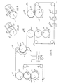
- a document such as a passport, driver's license, personal identification card, transit pass, or the like, includes a photograph 11 of the bearer.
- Written information 13 of the bearer is also provided on the surface of the document.
- the document can be paper, plastic or some other material that contains visual information to be protected from alteration.
- Covering at least the photograph 11 and the written information 13 is a see-through hologram authentication device of a type discussed in the patent applications cross-referenced above.
- Such a hologram reconstructs in reflected light images recorded in it, such as reconstructed images 15.
- the information 11 and 13 to be protected is covered with a hologram that allows the information to be observed through it at the same time as allowing the authenticating reconstructed images 15 to be observed.
- FIG. 1 A small area 17 of Figure 1 is expanded in Figure 2.
- Figure 3 shows a sectional view through the expanded portion of Figure 2.
- a hologram 19 is attached to a substrate 21 by an appropriate adhesive layer 20.
- the hologram 19 includes a substantially clear plastic film 23 having a surface relief pattern 25 formed on an inside surface thereof.
- the surface relief pattern 25 is continuous across at least a defined area of the hologram 19, continuing over the entire hologram in this example and thus the entire protected document.
- the surface relief pattern is formed from a master hologram by a standard embossing or casting technique.
- That portion of the surface relief pattern 25 to which a reflective layer is attached will be operative in reflecting incident light into the recorded image or other light pattern.
- reflective aluminum dots 27 are periodically spaced across the surface relief pattern 25 and attached to it in a manner to follow its contours. As described in considerably more detail in the applications cross-referenced above, this allows an image to be reconstructed from the hologram 19 in reflected light at the same time as the photograph 11 and other information attached through the substrate 21 is viewed through the hologram.
- the opaque, reflective dots 27 are made of a size and spaced apart sufficient for this to occur.
- the opaque metallization of the hologram surface relief pattern in the embodiment of Figure 1 is configured over an area of the protected document not covering the photograph 11 or other information 13 to provide a unique indicia that is separate, independent and unregistered from the images 15 reconstructed from the hologram.
- the indicia formed by the hologram metallization pattern is also separate and independent from the document information 11 and 13 being protected. In this case, that indicia is alphanumeric information, namely a month 29 and a year 31.
- the information or visual design of the protected document itself can also be changed each time that the hologram metallization pattern characters are changed but this technique allows use of other copies of the same document without change, if desired, for economics and simplicity.
- Figure 4 shows an expanded view of another small area 33 of the protected document of Figure 1. This includes a portion 35 of the "nine" of the year 31 that is visible from the face of the protected document of Figure 1. The number is formed by the shape of the reflective metallization layer that is applied to the surface relief pattern 25. The region 33 shown in Figure 4 illustrates that metallization pattern to retain the reflective dots around it. The metallization 35 also provides a reflective backing for reconstructing an image from the hologram surface relief pattern 25 covered by it.
- This information can be a month and year of expiration of the protected document, of a month during which the protected document is valid, and the like.
- new documents need to be issued periodically and it is quite expensive if an entirely new protective hologram needs to be constructed for use with each document reissue. What is most expensive is the making of an optical master hologram. But the technique of adding the indicia 29, 31 in a metallization step allows the same authenticating hologram to be utilized in successive reissues of the document since the metallization step occurs after the hologram replication step.
- a large number of such protective holograms can be manufactured for inventory with limited amounts periodically withdrawn and metallized with unique indicia 29, 31, but it generally is preferable to replicate each new issue of the protective hologram from the beginning. This still utilizes the same master hologram replicating plates for each issue, only the pattern of metallization changing. No new optical hologram master need be made.
- Figure 6 illustrates the process steps for forming hologram replicas on a continuous length of flexible substrate material 111.
- a first stage 113 applies liquid resin to defined areas of the web 111. Solidified, surface relief holograms are formed at station 115 in these resin areas.
- the web proceeds to a station 151 that prints a liquid onto the surface of the replica holograms in regions where reflective material is not to be attached.
- a next station 153 applies a reflective metal layer over the entire hologram replica surface relief pattern.
- a station 155 then removes the metallization layer from those areas that were printed at station 151 with a liquid material.
- the process web is dried and, at an optional station 159, a protective coating and/or adhesive layer is placed on the metallized surface relief pattern.
- a liquid bath 117 of casting resin has a first cylindrical roller 119 rotating about its axis through the liquid.
- the roller 119 transfers such liquid to outward surfaces of pads, such as pads 125 and 127, that are attached to an otherwise smooth cylindrical surface 123 of a drum shaped roller 123.
- a third roller 131 in the station 113 guides the web 111 in a path that results in contact between the pad surfaces of the roller 123 and the web without any relative motion therebetween.
- Guide rollers 133 and 135 also determine the paths of the web 111.
- liquid resin is applied from the bath 117 to discreet areas of the web 111 as defined by the size and pattern of the pads carried by the roller 123.
- the web 111 is passed in contact with the outside of the cylindrical drum 137 by appropriate guide rollers 139 and 141, in the second work station 115.
- the drum 137 has a plurality of individual hologram masters, such as pieces 143 and 145, attached to its outside surface. This arrangement is further shown in Figure 7. These hologram master pieces are arranged essentially in the same pattern as the pads of the drum 123. Rotation of the drums in the work stations 113 and 115 is coordinated by a master control 147 to cause the individual hologram pieces 143, 145, etc. to contact areas of the web 111 that have been coated with liquid resin by the pads 125, 127, etc.
- the web 111 and the hologram masters attached to the outside surface of the drum 137 move together without any motion between them.
- Liquid resin is held between each of the surface relief master holograms 143, 145, etc. and the web. While being so held, the liquid resin is hardened by curing with actinic radiation. A source 149 of such radiation directs it through the web 111 to the trapped liquid resin.
- actinic radiation directs it through the web 111 to the trapped liquid resin.
- the station 151 then coats each of the hologram replicas with a liquid material in a pattern of the desired non-continuous reflective metallization layer on the completed hologram.
- the web is directed around a drum shaped roller 161 and is guided away from it by rollers 163 and 165.
- a bath 167 of the liquid to be printed onto the hologram replicas is a water soluble resin, such as polyvinyl alcohol.
- This liquid is transferred by a roller 169 to the outer surface of a roller 171 which is urged into contact with the web against the roller 161.
- a cylindrical surface of the printing drum 171 contains a pattern 173 that corresponds with the desired pattern of metallization on the resulting hologram replica shown in Figure 1.
- the pattern 173 for a single hologram is constructed so that the liquid 167 is applied to all areas of the cast hologram relief pattern except for the regions of the desired metallization pattern 173. That is because the water soluble resin being applied will, in a subsequent step, simply be washed away and thus will remove any reflective material from the areas where the resin has been printed.
- the roller 171 is preferably formed from a gravure cylinder having liquid containing holes formed in a negative of the desired metallization pattern for the hologram replicas.
- the web 111 After application of the water soluble resin at the work station 151, the web 111 proceeds to a station 153 that coats the entire web on its side where the holograms are formed with an opaque, reflective material layer. That layer is preferably made of aluminum and the work station 153 is preferably a standard vacuum metallization machine.
- the web 111 advances to a station 155 which submerses the metallized hologram replicas in a water bath.
- the metal layer is sufficiently porous to allow water to penetrate through to the resin, thereby causing the resin applied at the station 151 to dissolve and the aluminum layer coated on such a resin to then be washed away.
- the next work station 157 simply dries the web by use of heat lamps and the like. Specific techniques and materials for use in the non-continuous metallization process of stations 151, 153, 155 and 157 are given in U.S. Patent Nos. 3,935,334 - Narui et al. (1976) and 4,242,378 - Arai (1980).
- a resin soluble in any one of a wide variety of organic solvents can be printed onto the web 111 prior to metallization.
- the metal layer is then removed in the pattern of the resin by submersing the coated web into a bath of the appropriate organic solvent.
- a final, optional work station 159 uniformly coats the metallized hologram replicas of the web 111 with a protective or adhesive layer from a liquid 174.
- a transfer roller 175 carries the liquid to the web 111 surface.
- the web 111 is guided by another roller 177. After an appropriate drying step, the metallized hologram replicas have such a desired additional layer.
- the web is then ready for separation into individual holograms by die cutting and the like for attachment to a document or other substrate surface to be protected. If it is desired to apply the individual holograms by a hot stamping process, the web 111 is then alternately attached by a hot melt adhesive to a flexible plastic carrier.
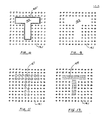
- a regular pattern of metallized dots 181 exists on the surface relief hologram replica.
- the letter "T” is formed by omitting dots in the region 183.
- This technique works well in cases where the size of the individual dots and the density of the background pattern 181 are clearly visible.
- the dot pattern can be made to be practically invisible to the ordinary user but still reconstruct holographic images, but in the case of Figure 9, such an invisible pattern of dots is not workable.
- the example of Figure 9 has an advantage of being able to place the "T" character 183 over information to be protected, such as the photograph 11 or writing 13 ( Figure 1), if desired, since none of the protected document is blocked by it.
- Figure 10 is an example similar to Figure 9 except that the region 183 without a dot pattern is outlined in a thin continuous metal pattern 185. This makes the letter "T" highly visible, even when the individual dots of the background pattern 181 may not be very visible, but does so without blocking view of much area of an underlying document to which the hologram is attached.
- Figures 11 and 12 utilize the fact of a background pattern 181 of dots clearly visible.
- the letter "T” is formed in Figure 11 by a pattern 187 of reflective dots that are larger than those of the regular background pattern 181.
- the pattern of the dots 187 is the same as that of the background dots 181 but they are more dense and thus the pattern is distinguishable from the background.
- the pattern 189 in Figure 12 is made to be different from the background pattern 181, and distinguishable because of that feature.
- the density of the area covered by dots in the pattern 189 may be the same as that of the background pattern 181.
Abstract
Description
- This is related to application serial no. 07/291,247, filed December 23,1988, which is a continuation-in-part of application serial no. 07/160,641, filed February 26, 1988, now abandoned, and which in turn is a continuation-in-part of application serial no. 07/156,305, filed February 12, 1988, now abandoned. A corresponding European patent application no. 89102182.6 was published August 16, 1989 as no. 328,086, and is incorporated herein by this reference.
- This invention relates generally to the optical arts of holography and diffraction gratings, and more particularly, to a special forms of these optical devices for use in authenticating documents and other items as genuine.
- There is a wide-spread need to authenticate written information and articles in order to prevent both the counterfeiting of the article and an alteration of a genuine article. Examples of such articles include credit cards, identification cards, driver's licenses, transit passes, passports, stock certificates, and the like. Holograms are currently being extensively used on credit cards and transit passes, for example. An image having observable three-dimensional characteristics is viewable in light reflected from such a hologram.
- Because holograms are difficult to make and require a high level of technical sophistication, the difficulty of making a counterfeit credit card, or other article to which a hologram is attached, is increased. A master hologram is made in an optical laboratory with coherent light. The resulting master hologram is capable of reconstructing an image of the object from which it is made. Low-cost replicas are then made from that master. Several specific replication techniques are known, the most common currently being to make the master in a manner that the object information is stored in a surface relief pattern. This surface relief pattern is then used to make replicas by an embossing or casting operation. A layer of reflective material is applied to each replica surface relief pattern so that the image may be viewed in light reflected from that pattern. The holograms are then firmly attached to the credit card or other article to be authenticated. The hologram is also constructed of suitable materials so that an attempt to remove the hologram from the article will destroy it, thereby eliminating the possibility of a counterfeiter transferring a hologram from a genuine article and onto a counterfeit article.
- An authenticating hologram of this type cannot cover printing, photographs and the like carried by the article to be authenticated when that information wants to be viewed. This is because the reflective layer of the hologram is substantially opaque so that any visual information on the article in the area to which it is attached is covered by the hologram. Some credit cards are authenticating some of the raised alpha-numeric information on them by covering at least a few of the characters with the hologram. But any printing, photographs or the like on a flat surface under the hologram is not viewable.
- There has been some effort to control the amount of reflective material that is applied to the surface relief hologram so that it will both reflect enough light in order to reconstruct an image recorded in the hologram and at the same time be transparent enough to make visible any printing, photograph or other visual information under the hologram. Besides authenticating the article to which the hologram is attached and the visual information under it, such a hologram has the potential of preventing alteration of that information on an authentic article. It has been found to be very difficult, however, to be able to repeatedly form a reflective layer on the hologram that gives it these advantageous characteristics. Aluminum is usually employed as the reflective material. A proper thickness of that layer can result in the desired partial transparency and partial reflection, but the processes used to date have been very difficult to control in order to provide the proper thickness.
- Holograms are also being used to authenticate documents, such as transit passes, that are reissued at frequent periodic intervals, such as monthly. It is often desired that the hologram be changed each month so that transit authorities can easily recognize a valid current transit pass from an expired one. This presently requires making a new optical master hologram for each new pass, an expensive and time consuming process.
- Therefore, it is a specific object of the present invention to provide an improved hologram or diffraction grating for attaching to a document or article over visual information that is to be protected, wherein the information can be observed through the hologram and an image reconstructed from the hologram may be observed.
- It is another object of the present invention to provide an authentication hologram or diffraction grating, and process for making it, that allows easy modification for monthly transit passes and the like without having to make a new optical master.
- It is a more general object of the present invention to provide novel holograms and diffraction gratings for authentication of documents and other articles.
- These and additional objects are accomplished by the articles and processes of the present invention, wherein, briefly, a continuous hologram or diffraction grating device is provided from which an image or other recognizable pattern is reconstructed in light reflected from the device but light reflective material is discontinuously provided in distinctive shapes such as one or more alpha-numeric characters. The reflective material pattern can thus be selected to convey information which is independent of that recorded on the hologram or diffraction grating. In the case of transit passes discussed above, for example, the same hologram or diffraction grating can be used for each month's pass, the pattern of reflective material clearly indicating the current month for which the pass is valid. This technique is optimally combined with a non-continuously reflective hologram or diffraction pattern that covers information on a substrate to be protected but the technique can also be used as part of an otherwise solid hologram that is attached to a substrate along side information desired to be visible.
- Additional objects, advantages and features of the various aspects of the present invention will become apparent from the following description of the preferred embodiments thereof, which description should be taken in conjunction with the accompanying drawings.
-
- Figure 1 illustrates an article having visual information that is protected by an improved hologram of the present invention being attached thereto;
- Figure 2 is an expanded view of a portion of the protected article of Figure 1;
- Figure 3 is a cross-sectional view of the structure of Figure 2 taken across section 3-3 thereof;
- Figure 4 is an expanded view of another portion of the protected article of Figure 1;
- Figure 5 is a cross-sectional view of the structure of Figure 4, taken across section 5-5 thereof;
- Figure 6 illustrates a continuous process for making a hologram or diffraction grating of a type used to authenticate an article, such as shown in Figure 1;
- Figures 7 and 8 show individual components used in the process of Figure 6; and
- Figures 9-12 shows some alternative structures of a hologram or diffraction grating made according to the process illustrated in Figures 6-8.
- Referring initially to Figure 1, an example is given of an article having a protective hologram attached that utilizes the present invention. A document, such as a passport, driver's license, personal identification card, transit pass, or the like, includes a photograph 11 of the bearer. Written
information 13 of the bearer is also provided on the surface of the document. The document can be paper, plastic or some other material that contains visual information to be protected from alteration. Covering at least the photograph 11 and the writteninformation 13 is a see-through hologram authentication device of a type discussed in the patent applications cross-referenced above. Such a hologram reconstructs in reflected light images recorded in it, such as reconstructedimages 15. Thus, theinformation 11 and 13 to be protected is covered with a hologram that allows the information to be observed through it at the same time as allowing the authenticating reconstructedimages 15 to be observed. - A
small area 17 of Figure 1 is expanded in Figure 2. Figure 3 shows a sectional view through the expanded portion of Figure 2. Ahologram 19 is attached to a substrate 21 by an appropriate adhesive layer 20. Thehologram 19 includes a substantially clearplastic film 23 having asurface relief pattern 25 formed on an inside surface thereof. Thesurface relief pattern 25 is continuous across at least a defined area of thehologram 19, continuing over the entire hologram in this example and thus the entire protected document. The surface relief pattern is formed from a master hologram by a standard embossing or casting technique. - That portion of the
surface relief pattern 25 to which a reflective layer is attached will be operative in reflecting incident light into the recorded image or other light pattern. In the hologram portion illustrated in Figures 2 and 3,reflective aluminum dots 27 are periodically spaced across thesurface relief pattern 25 and attached to it in a manner to follow its contours. As described in considerably more detail in the applications cross-referenced above, this allows an image to be reconstructed from thehologram 19 in reflected light at the same time as the photograph 11 and other information attached through the substrate 21 is viewed through the hologram. The opaque,reflective dots 27 are made of a size and spaced apart sufficient for this to occur. - In addition to the reflective dots, the opaque metallization of the hologram surface relief pattern in the embodiment of Figure 1 is configured over an area of the protected document not covering the photograph 11 or
other information 13 to provide a unique indicia that is separate, independent and unregistered from theimages 15 reconstructed from the hologram. The indicia formed by the hologram metallization pattern is also separate and independent from thedocument information 11 and 13 being protected. In this case, that indicia is alphanumeric information, namely amonth 29 and ayear 31. The information or visual design of the protected document itself can also be changed each time that the hologram metallization pattern characters are changed but this technique allows use of other copies of the same document without change, if desired, for economics and simplicity. - Figure 4 shows an expanded view of another
small area 33 of the protected document of Figure 1. This includes aportion 35 of the "nine" of theyear 31 that is visible from the face of the protected document of Figure 1. The number is formed by the shape of the reflective metallization layer that is applied to thesurface relief pattern 25. Theregion 33 shown in Figure 4 illustrates that metallization pattern to retain the reflective dots around it. Themetallization 35 also provides a reflective backing for reconstructing an image from the hologramsurface relief pattern 25 covered by it. - This information can be a month and year of expiration of the protected document, of a month during which the protected document is valid, and the like. In such cases, new documents need to be issued periodically and it is quite expensive if an entirely new protective hologram needs to be constructed for use with each document reissue. What is most expensive is the making of an optical master hologram. But the technique of adding the
indicia unique indicia - Such a technique is illustrated generally in Figures 6-8. Figure 6 illustrates the process steps for forming hologram replicas on a continuous length of flexible substrate material 111. There are several distinct processing stages through which the web 111 passes. A
first stage 113 applies liquid resin to defined areas of the web 111. Solidified, surface relief holograms are formed at station 115 in these resin areas. Next, the web proceeds to a station 151 that prints a liquid onto the surface of the replica holograms in regions where reflective material is not to be attached. Anext station 153 applies a reflective metal layer over the entire hologram replica surface relief pattern. Astation 155 then removes the metallization layer from those areas that were printed at station 151 with a liquid material. Next, at station 157, the process web is dried and, at an optional station 159, a protective coating and/or adhesive layer is placed on the metallized surface relief pattern. - Details of the hologram
replica casting stations 113 and 115 can be had from copending patent application Serial No. 399,812, filed August 29, 1989, the disclosure of which is incorporated herein by this reference. Briefly, aliquid bath 117 of casting resin has a first cylindrical roller 119 rotating about its axis through the liquid. The roller 119 transfers such liquid to outward surfaces of pads, such aspads 125 and 127, that are attached to an otherwise smoothcylindrical surface 123 of a drum shapedroller 123. - A
third roller 131 in thestation 113 guides the web 111 in a path that results in contact between the pad surfaces of theroller 123 and the web without any relative motion therebetween.Guide rollers bath 117 to discreet areas of the web 111 as defined by the size and pattern of the pads carried by theroller 123. - After leaving the
station 113, the web 111 is passed in contact with the outside of thecylindrical drum 137 byappropriate guide rollers drum 137 has a plurality of individual hologram masters, such aspieces drum 123. Rotation of the drums in thework stations 113 and 115 is coordinated by amaster control 147 to cause theindividual hologram pieces pads 125, 127, etc. - The web 111 and the hologram masters attached to the outside surface of the
drum 137 move together without any motion between them. Liquid resin is held between each of the surfacerelief master holograms roller 141, the liquid resin has been cured with the desired surface relief pattern formed therein. The web 111 is separated from thehologram masters - The station 151 then coats each of the hologram replicas with a liquid material in a pattern of the desired non-continuous reflective metallization layer on the completed hologram. The web is directed around a drum shaped
roller 161 and is guided away from it byrollers bath 167 of the liquid to be printed onto the hologram replicas is a water soluble resin, such as polyvinyl alcohol. This liquid is transferred by aroller 169 to the outer surface of aroller 171 which is urged into contact with the web against theroller 161. As can be seen from Figure 8, a cylindrical surface of theprinting drum 171 contains apattern 173 that corresponds with the desired pattern of metallization on the resulting hologram replica shown in Figure 1. In this case, thepattern 173 for a single hologram is constructed so that the liquid 167 is applied to all areas of the cast hologram relief pattern except for the regions of the desiredmetallization pattern 173. That is because the water soluble resin being applied will, in a subsequent step, simply be washed away and thus will remove any reflective material from the areas where the resin has been printed. Theroller 171 is preferably formed from a gravure cylinder having liquid containing holes formed in a negative of the desired metallization pattern for the hologram replicas. - After application of the water soluble resin at the work station 151, the web 111 proceeds to a
station 153 that coats the entire web on its side where the holograms are formed with an opaque, reflective material layer. That layer is preferably made of aluminum and thework station 153 is preferably a standard vacuum metallization machine. - Next, the web 111 advances to a
station 155 which submerses the metallized hologram replicas in a water bath. The metal layer is sufficiently porous to allow water to penetrate through to the resin, thereby causing the resin applied at the station 151 to dissolve and the aluminum layer coated on such a resin to then be washed away. The next work station 157 simply dries the web by use of heat lamps and the like. Specific techniques and materials for use in the non-continuous metallization process ofstations - As an alternative to using a water soluble resin, a resin soluble in any one of a wide variety of organic solvents can be printed onto the web 111 prior to metallization. The metal layer is then removed in the pattern of the resin by submersing the coated web into a bath of the appropriate organic solvent.
- A final, optional work station 159 uniformly coats the metallized hologram replicas of the web 111 with a protective or adhesive layer from a liquid 174. A
transfer roller 175 carries the liquid to the web 111 surface. The web 111 is guided by anotherroller 177. After an appropriate drying step, the metallized hologram replicas have such a desired additional layer. The web is then ready for separation into individual holograms by die cutting and the like for attachment to a document or other substrate surface to be protected. If it is desired to apply the individual holograms by a hot stamping process, the web 111 is then alternately attached by a hot melt adhesive to a flexible plastic carrier. - The example of the
unique indicia 29, 31 (Figure 1) formed during the reflective metallization step was described to be formed of solid reflective material. It is not necessary, however, that the alphanumeric characters be solid. That is only one of many specific implementations. Four additional specific implements are illustrated in Figures 9-12 for representing the letter "T" in the pattern of aluminization. - Referring initially to Figure 9, a regular pattern of metallized
dots 181 exists on the surface relief hologram replica. The letter "T" is formed by omitting dots in theregion 183. This technique works well in cases where the size of the individual dots and the density of thebackground pattern 181 are clearly visible. The dot pattern can be made to be practically invisible to the ordinary user but still reconstruct holographic images, but in the case of Figure 9, such an invisible pattern of dots is not workable. The example of Figure 9 has an advantage of being able to place the "T"character 183 over information to be protected, such as the photograph 11 or writing 13 (Figure 1), if desired, since none of the protected document is blocked by it. - Figure 10 is an example similar to Figure 9 except that the
region 183 without a dot pattern is outlined in a thin continuous metal pattern 185. This makes the letter "T" highly visible, even when the individual dots of thebackground pattern 181 may not be very visible, but does so without blocking view of much area of an underlying document to which the hologram is attached. - Figures 11 and 12 utilize the fact of a
background pattern 181 of dots clearly visible. The letter "T" is formed in Figure 11 by apattern 187 of reflective dots that are larger than those of theregular background pattern 181. The pattern of thedots 187 is the same as that of thebackground dots 181 but they are more dense and thus the pattern is distinguishable from the background. Thepattern 189 in Figure 12 is made to be different from thebackground pattern 181, and distinguishable because of that feature. The density of the area covered by dots in thepattern 189 may be the same as that of thebackground pattern 181. - The examples described above result in the making of a large number of hologram replicas with the same alpha-numeric characters formed in the metal layer of each. Alternatively, these characters can be formed by use of a printing technique that places a unique pattern on each hologram replica. This is useful, for example, where each hologram replica of a large batch of replicas is to carry a unique identifying serial number that is clearly visible in the metal layer. This can be accomplished by jet or laser printing techniques, by use of a mechanically indexed print head included as part of the
drum 171, etc., to form a soluble layer pattern that is somewhat different for each replica. - Although the various aspects of the present invention have been described with respect to their preferred embodiments, it will be understood that the invention is entitled to protection within the full scope of the appended claims.
Claims (22)
- In a combination of an article having a hologram or diffraction grating device attached to a surface thereof, said device being characterized by a surface relief pattern that reflects and diffracts incident light from portions backed by a reflective layer to form an image or other light pattern recorded therein, an improvement wherein said reflective layer includes at least a portion thereof only partially covering the surface relief pattern in a shape that conveys visual information separate from that of said image or other light pattern.
- The combination of claim 1 wherein the portion of the reflective layer that is shaped to convey visual information is shaped at least in part to form one or more alpha-numeric characters.
- The combination of either claim 1 or 2 wherein the reflective layer is attached to the device surface relief pattern.
- A document having visual information thereon protected from alteration, comprising a hologram or diffraction grating device firmly attached to said document over at least a portion of said visual information, said device comprising:
a discontinuous pattern of a surface relief pattern formed in a substantially transparent layer with substantially completely reflective material therebehind in a manner that the device, when illuminated with light, allows viewing of both the visual information on the document and a light image or pattern reconstructed from said surface relief pattern, and
said reflective material additionally being arranged in a shape or pattern of visual information separate from that of the reconstructed image or pattern and also separate from the document visual information. - The combination of claim 4 wherein the visual information conveying arrangement of the reflective material includes one or more substantially solid alpha-numeric characters.
- The combination of claim 4 wherein the visual information arrangement of the reflective material is formed by a second discontinuous pattern thereof distinct from the surrounding discontinuous pattern and in a shape of one or more alpha-numeric characters.
- The combination of claim 4 wherein the visual information arrangement of the reflective material is formed by omitting the discontinuous pattern thereof in a shape of one or more alpha-numeric characters.
- The combination of claim 7 wherein the omitted discontinuous pattern of reflective material is further outlined in said reflective material in a manner to form said one or more alpha-numeric characters.
- The combination of any of claims 4-8 wherein the device surface relief pattern is continuous over said at least a portion of the visual information and wherein the reflective material is provided as a layer attached to said surface relief pattern.
- The combination of either of claims 4 or 5 wherein the visual information arrangement of the reflective material is substantially non-overlapping with the document visual information, thereby not interfering therewith.
- The combination of any one of claims 4, 6, 7, or 8 wherein the visual information conveying arrangement of the reflective material at least partially overlaps with the document visual information.
- At least first and second documents having visual information thereon protected from alteration, comprising:
first and second hologram or diffraction grating devices that are respectively firmly attached to said first and second documents over at least a portion of the visual information carried by each,
said first and second devices having substantially the same continuous surface relief pattern formed in a substantially transparent layer and containing information of substantially the same light image, and a discontinuous pattern of substantially completely reflective material provided behind said surface relief pattern, said discontinuous pattern being arranged so that the device, when illuminated with light, allows viewing of both the visual information on the document and an image reconstructed from portions of said surface relief pattern containing reflective material,
the reflective material of the first device additionally being arranged to form at least a first distinctive indicia that is separate from that of the device light image or document visual information, and
the reflective material of the second device additionally being arranged to form at least a second distinctive indicia that is separate from that of the device light image or document visual information. - The arrangement of claim 12 wherein the visual information on each of the first and second documents is substantially the same.
- The arrangement of claim 12 wherein the first and second distinctive indicia each include at least one alpha-numeric character different from the other.
- An authentication device, comprising:
a substantially transparent sheet of material containing on one side thereof a surface relief pattern that is continuous over a least a portion of the area thereof and which is in the form of a hologram or diffraction pattern from which a light image or pattern can be formed upon illumination,
a discontinuous pattern of substantially completely reflective material conforming to said surface relief pattern in a manner that said light image or pattern is reflected therefrom while also allowing viewing therethrough, said reflective material additionally being arranged in a distinctive indicia that is separate from the light image or pattern of the hologram or diffraction pattern, and
means carried by said one side of the transparent sheet for attaching the device to a substrate. - The combination of claim 15 wherein the distinctive indicia arrangement of the reflective material includes one or more substantially solid characters.
- The combination of claim 15 wherein the distinctive indicia arrangement of the reflective material is formed by a second discontinuous pattern thereof distinct from the surrounding discontinuous pattern and in a shape of one or more characters.
- The combination of claim 15 wherein the distinctive indicia arrangement of the reflective material is formed by omitting the discontinuous pattern thereof in a shape of one or more characters.
- The combination of claim 18 wherein the omitted discontinuous pattern of reflective material is further outlined in said reflective material in a manner to form said one or more characters.
- At least first and second hologram or light diffraction devices formed from replicas of a light interference pattern recorded as a common surface relief pattern on one side of a substantially transparent sheet, wherein said first device includes a pattern of discontinuous substantially opaque reflective material conforming to a first replica of said common surface relief pattern and arranged to include a first distinctive indicia, and wherein said second device includes a pattern of discontinuous substantially opaque reflective material conforming to a second replica of said common surface relief pattern and arranged to include a second distinctive indicia, whereby said first and second devices can be efficiently made from a single surface relief pattern but yet be visually distinct.
- A method of making at least two visually distinct hologram or diffraction devices from a common surface relief master pattern, comprising the steps of:
forming at least first and second replicas of the common surface relief pattern on one side of each of first and second sheets of substantially optically clear material,
forming a first non-continuous, substantially opaque reflective layer conforming to the surface relief pattern of the first replica and with a visible pattern that contains a first distinct indicia, thereby forming a first device, and
forming a second non-continuous, substantially opaque reflective layer conforming to the surface relief pattern of the second replica and with a visible pattern that contains a second distinct indicia, thereby forming a second device,
whereby said first and second devices can be efficiently made from a single surface relief master pattern but yet be visually distinct. - A method of authenticating visual information on a surface of an article, comprising the steps of:
forming in a surface of a substantially transparent substrate a continuous relief pattern over an area thereof that is capable of forming a recognizable image upon polychromatic viewing light being reflected from the surface relief pattern,
forming a discontinuous, substantially opaque reflective layer over said surface relief area with a pattern that allows both viewing through the substrate in said area and viewing of an image reconstructed from the portions thereof to which said reflective material is attached, said reflective layer pattern also being shaped to form a visual indicia that is distinct from both the visual information on the article surface and the image formed in light reflected from it, and
attaching said substrate firmly to said article in a position with said surface relief area positioned at least partially over said visual information, thereby to authenticate said visual information.
Applications Claiming Priority (2)
| Application Number | Priority Date | Filing Date | Title |
|---|---|---|---|
| US470121 | 1983-02-28 | ||
| US07/470,121 US5044707A (en) | 1990-01-25 | 1990-01-25 | Holograms with discontinuous metallization including alpha-numeric shapes |
Publications (2)
| Publication Number | Publication Date |
|---|---|
| EP0439092A2 true EP0439092A2 (en) | 1991-07-31 |
| EP0439092A3 EP0439092A3 (en) | 1993-03-17 |
Family
ID=23866357
Family Applications (1)
| Application Number | Title | Priority Date | Filing Date |
|---|---|---|---|
| EP19910100686 Withdrawn EP0439092A3 (en) | 1990-01-25 | 1991-01-21 | Holograms with discontinuous metallization including alphanumeric shapes |
Country Status (3)
| Country | Link |
|---|---|
| US (1) | US5044707A (en) |
| EP (1) | EP0439092A3 (en) |
| JP (1) | JPH04212984A (en) |
Cited By (19)
| Publication number | Priority date | Publication date | Assignee | Title |
|---|---|---|---|---|
| WO1992022039A1 (en) * | 1991-06-05 | 1992-12-10 | Mikoh Pty. Ltd. | Optical memories incorporating diffraction gratings |
| DE4236254A1 (en) * | 1992-10-20 | 1994-04-21 | Elmar Radzik | Visitor's card with base body and picture on latter part - has holographic picture on laminated base body, with one layer transparent |
| AU664202B2 (en) * | 1991-10-14 | 1995-11-09 | Landis & Gyr Betriebs Ag | Security element |
| WO1996007543A1 (en) * | 1994-09-03 | 1996-03-14 | Leonhard Kurz Gmbh & Co. | Dot-matrix image and thermal transfer foil for producing the same |
| WO1996007552A1 (en) * | 1994-09-03 | 1996-03-14 | Leonhard Kurz Gmbh & Co. | Dot-matrix image and thermal transfer film for producing the same |
| US5538753A (en) * | 1991-10-14 | 1996-07-23 | Landis & Gyr Betriebs Ag | Security element |
| AU671588B2 (en) * | 1991-06-05 | 1996-09-05 | Mikoh Pty. Ltd. | Optical memories incorporating diffraction gratings |
| WO1999012748A1 (en) * | 1997-09-05 | 1999-03-18 | Giesecke & Devrient Gmbh | Device for producing a substrate with an optically variable structure |
| WO2002044439A1 (en) * | 2000-11-29 | 2002-06-06 | Mipa S.P.A. | Process for the preparation of printed and partially metalized plastic films |
| WO2007140485A2 (en) * | 2006-05-31 | 2007-12-06 | Cabot Corporation | Printable reflective features formed from multiple inks and processes for making them |
| WO2008000351A2 (en) * | 2006-06-27 | 2008-01-03 | Giesecke & Devrient Gmbh | Security element |
| WO2008061743A1 (en) | 2006-11-25 | 2008-05-29 | Leonhard Kurz Stiftung & Co. Kg | Laminating film for coating a metal substrate which can be cold-formed |
| EP2461203B1 (en) | 2005-05-18 | 2017-12-13 | Visual Physics, LLC | Image presentation and micro-optic security system |
| EP2635444B1 (en) | 2010-11-02 | 2019-03-13 | OVD Kinegram AG | Security element and method for producing a security element |
| US10366314B1 (en) | 2018-03-06 | 2019-07-30 | Capital One Services, Llc | Protecting private information provided on a transaction card and/or a document with a reflective element |
| US10766292B2 (en) | 2014-03-27 | 2020-09-08 | Crane & Co., Inc. | Optical device that provides flicker-like optical effects |
| US10800203B2 (en) | 2014-07-17 | 2020-10-13 | Visual Physics, Llc | Polymeric sheet material for use in making polymeric security documents such as banknotes |
| US10974535B2 (en) | 2014-03-27 | 2021-04-13 | Visual Physics, Llc | Optical device that produces flicker-like optical effects |
| US11590791B2 (en) | 2017-02-10 | 2023-02-28 | Crane & Co., Inc. | Machine-readable optical security device |
Families Citing this family (69)
| Publication number | Priority date | Publication date | Assignee | Title |
|---|---|---|---|---|
| US5314767A (en) * | 1988-01-25 | 1994-05-24 | Bussard Janice W | Holographic products with improved seals |
| US5455129A (en) * | 1988-01-25 | 1995-10-03 | Bussard; Janice W. | Holographic products with sealed edges |
| US5442433A (en) * | 1989-08-11 | 1995-08-15 | Nhk Spring Co., Ltd. | Identification system for an article having individually attached patches |
| DE3932505C2 (en) * | 1989-09-28 | 2001-03-15 | Gao Ges Automation Org | Data carrier with an optically variable element |
| GB8924111D0 (en) * | 1989-10-26 | 1989-12-13 | Amblehurst Ltd | Optical device |
| JPH06502028A (en) * | 1991-09-06 | 1994-03-03 | プリズマジック・インコーポレーテッド | Flexible material with optical diffraction properties and its manufacturing method |
| JPH07111726B2 (en) * | 1991-12-26 | 1995-11-29 | 日本発条株式会社 | Identification structure and identification object |
| JP2520346B2 (en) * | 1992-04-28 | 1996-07-31 | 日本発条株式会社 | Object identification structure |
| US5331443A (en) * | 1992-07-31 | 1994-07-19 | Crown Roll Leaf, Inc. | Laser engraved verification hologram and associated methods |
| US5695808A (en) * | 1993-04-16 | 1997-12-09 | Crown Roll Leaf Inc. | Method for making transparent reflective films |
| US5351142A (en) * | 1993-04-16 | 1994-09-27 | Crown Roll Leaf, Inc. | Semi-transparent reflective layer for a phase hologram |
| US5513019A (en) * | 1993-04-16 | 1996-04-30 | Crown Roll Leaf, Inc. | Semi-transparent reflective layer for a phase hologram |
| US6461544B1 (en) | 1993-05-03 | 2002-10-08 | Crown Roll Leaf, Inc. | Two-dimensional/three-dimensional graphic material and method of making same |
| EP0644508B1 (en) * | 1993-08-31 | 1999-12-22 | Control Module, Inc. | Secure optical identification method and means |
| US5464710A (en) * | 1993-12-10 | 1995-11-07 | Deposition Technologies, Inc. | Enhancement of optically variable images |
| US5585144A (en) * | 1994-02-22 | 1996-12-17 | Crown Roll Leaf, Inc. | Hologram with integral printed indicia |
| US5464690A (en) * | 1994-04-04 | 1995-11-07 | Novavision, Inc. | Holographic document and method for forming |
| US5576853A (en) * | 1994-12-20 | 1996-11-19 | Polaroid Corporation | Apparatus and methods for making transmission holograms |
| US5704651A (en) * | 1995-05-25 | 1998-01-06 | Verify First Technologies, Inc. | Counterfeit resistant documents and methods |
| US5772248A (en) * | 1995-12-07 | 1998-06-30 | Verify First Technologies, Inc. | Document with tamper and counterfeit resistant relief markings |
| US5873604A (en) * | 1995-05-25 | 1999-02-23 | Verify First Technologies, Inc. | Document security system having thermo-activated pantograph and validation mark |
| US5762378A (en) * | 1996-02-16 | 1998-06-09 | Verify First Technologies, Inc. | Tamper resistant validation marks |
| US6573983B1 (en) | 1996-11-15 | 2003-06-03 | Diebold, Incorporated | Apparatus and method for processing bank notes and other documents in an automated banking machine |
| US5923413A (en) | 1996-11-15 | 1999-07-13 | Interbold | Universal bank note denominator and validator |
| US5838466A (en) * | 1996-12-13 | 1998-11-17 | Printpack Illinois, Inc. | Hidden Holograms and uses thereof |
| GB9709263D0 (en) | 1997-05-07 | 1997-06-25 | Astor Universal Limited | Laminate structure |
| US5951769A (en) | 1997-06-04 | 1999-09-14 | Crown Roll Leaf, Inc. | Method and apparatus for making high refractive index (HRI) film |
| US6087075A (en) * | 1997-11-07 | 2000-07-11 | Label Systems, Inc. | Holographic tamper-evident label |
| US6930606B2 (en) * | 1997-12-02 | 2005-08-16 | Crane & Co., Inc. | Security device having multiple security detection features |
| US6655719B1 (en) | 1998-02-05 | 2003-12-02 | Yoram Curiel | Methods of creating a tamper resistant informational article |
| US6638386B2 (en) | 2000-04-19 | 2003-10-28 | Novavision, Inc. | Method for making holographic foil |
| US6497778B1 (en) | 2000-04-19 | 2002-12-24 | Novavision, Inc. | Method for making holographic foil |
| GB0015871D0 (en) * | 2000-06-28 | 2000-08-23 | Rue De Int Ltd | A security device |
| JP3900811B2 (en) * | 2000-09-12 | 2007-04-04 | 大日本インキ化学工業株式会社 | Metallic hologram |
| GB2367220B (en) * | 2000-09-22 | 2004-02-18 | Mitel Semiconductor Ab | Serialised test of parellel optical module |
| US6929761B2 (en) * | 2001-04-19 | 2005-08-16 | Sagoma Plastics Corporation | Molded hologram apparatus method and product |
| WO2002093474A1 (en) * | 2001-05-11 | 2002-11-21 | De La Rue International Limited | Improvements relating to security articles |
| GB0220315D0 (en) * | 2002-09-02 | 2002-10-09 | Dubois Ltd | Security marketing |
| CN1440877B (en) * | 2003-04-11 | 2010-09-01 | 陈旃 | Anti-fake public traffic monthly ticket |
| AT501356A1 (en) * | 2003-06-18 | 2006-08-15 | Hueck Folien Gmbh | SAFETY ELEMENTS AND SAFETY FEATURES WITH COLOR EFFECTS |
| DE10353092A1 (en) * | 2003-11-12 | 2005-06-16 | Giesecke & Devrient Gmbh | Data carrier with markings |
| US7370808B2 (en) * | 2004-01-12 | 2008-05-13 | Symbol Technologies, Inc. | Method and system for manufacturing radio frequency identification tag antennas |
| WO2005086075A1 (en) * | 2004-03-01 | 2005-09-15 | International Barcode Corporation | Diffractive optical variable image including barcode |
| CN1953878A (en) * | 2004-04-05 | 2007-04-25 | 克瑞尼股份有限公司 | Counterfeit-resistant, metal-formed images and security devices and security documents employing same |
| US20050273434A1 (en) * | 2004-04-18 | 2005-12-08 | Allen Lubow | System and method for managing security in a supply chain |
| US7303127B2 (en) * | 2004-07-29 | 2007-12-04 | Sandisk Corporation | Packaged memory devices with various unique physical appearances |
| US20070190133A1 (en) * | 2004-10-27 | 2007-08-16 | Bunick Frank J | Dosage forms having a microreliefed surface and methods and apparatus for their production |
| US20060088593A1 (en) * | 2004-10-27 | 2006-04-27 | Bunick Frank J | Dosage forms having a microreliefed surface and methods and apparatus for their production |
| US20070281022A1 (en) * | 2004-10-27 | 2007-12-06 | Bunick Frank J | Dosage forms having a microreliefed surface and methods and apparatus for their production |
| US20060087051A1 (en) * | 2004-10-27 | 2006-04-27 | Bunick Frank J | Dosage forms having a microreliefed surface and methods and apparatus for their production |
| US20060088586A1 (en) * | 2004-10-27 | 2006-04-27 | Bunick Frank J | Dosage forms having a microreliefed surface and methods and apparatus for their production |
| US8383159B2 (en) * | 2004-10-27 | 2013-02-26 | Mcneil-Ppc, Inc. | Dosage forms having a microreliefed surface and methods and apparatus for their production |
| US7525705B2 (en) * | 2004-11-03 | 2009-04-28 | Jds Uniphase Corporation | Continually variable demetallization of metallized films and similar objects |
| ATE500070T1 (en) * | 2004-12-23 | 2011-03-15 | Arjowiggins Security | SECURITY ELEMENT WITH A DIGITAL FEATURE AND SECURITY ITEM OR DOCUMENT WITH THE SAME. |
| GB0600323D0 (en) * | 2006-01-09 | 2006-02-15 | Rue De Int Ltd | Improved optically variable magnetic stripe |
| US7829162B2 (en) | 2006-08-29 | 2010-11-09 | international imagining materials, inc | Thermal transfer ribbon |
| DE102007057658A1 (en) * | 2007-02-07 | 2009-06-04 | Leonhard Kurz Stiftung & Co. Kg | Security document in the form of a multilayer film body for viewing in incident light and in transmitted light, comprises a carrier film and a partial metallic reflective layer in a first region that is transparent or semi-transparent |
| EP2109014A1 (en) * | 2008-04-08 | 2009-10-14 | JDS Uniphase Corporation | Improved OVD containing device |
| US20100206953A1 (en) | 2009-02-19 | 2010-08-19 | O'boyle Lily | Durable washable label having a visible diffraction grating pattern |
| JP5545289B2 (en) * | 2009-06-18 | 2014-07-09 | 凸版印刷株式会社 | Optical element manufacturing method |
| CA2825655C (en) | 2011-01-28 | 2019-04-30 | Crane & Co., Inc. | A laser marked device |
| MX2014001926A (en) | 2011-08-19 | 2014-08-21 | Visual Physics Llc | Optionally transferable optical system with a reduced thickness. |
| CN102855515B (en) * | 2012-04-23 | 2015-06-17 | 东港安全印刷股份有限公司 | Holographic gradient identification card |
| CA2881826C (en) | 2012-08-17 | 2021-03-30 | Visual Physics, Llc | A process for transferring microstructures to a final substrate |
| CA2904356C (en) | 2013-03-15 | 2022-03-08 | Visual Physics, Llc | Optical security device |
| US9873281B2 (en) | 2013-06-13 | 2018-01-23 | Visual Physics, Llc | Single layer image projection film |
| AU2015317844B2 (en) | 2014-09-16 | 2019-07-18 | Crane Security Technologies, Inc. | Secure lens layer |
| DE102014118366A1 (en) * | 2014-12-10 | 2016-06-16 | Ovd Kinegram Ag | Multilayer body and method for its production |
| MX2017010258A (en) | 2015-02-11 | 2018-03-23 | Crane & Co Inc | Method for the surface application of a security device to a substrate. |
Citations (6)
| Publication number | Priority date | Publication date | Assignee | Title |
|---|---|---|---|---|
| GB2136352A (en) * | 1982-12-03 | 1984-09-19 | Hollusions Limited | Hologram Devices and Method of Manufacture |
| JPS61176968A (en) * | 1985-01-31 | 1986-08-08 | Dainippon Printing Co Ltd | Multiple recording material |
| JPS6232486A (en) * | 1985-08-05 | 1987-02-12 | Dainippon Printing Co Ltd | Pattern-shaped hologram transferring sheet |
| JPS62212682A (en) * | 1986-03-14 | 1987-09-18 | Dainippon Printing Co Ltd | Patterned hologram transfer sheet |
| EP0253089A1 (en) * | 1986-07-10 | 1988-01-20 | Landis & Gyr Betriebs AG | Multi-layer document |
| DE4025296A1 (en) * | 1989-08-09 | 1991-02-14 | Dainippon Printing Co Ltd | SHEET FOR PRODUCING A HOLOGRAM AND METHOD FOR THE PRODUCTION THEREOF |
Family Cites Families (15)
| Publication number | Priority date | Publication date | Assignee | Title |
|---|---|---|---|---|
| US3282720A (en) * | 1963-11-01 | 1966-11-01 | Avco Corp | Method of applying signatures to negotiable instruments |
| GB1423952A (en) * | 1973-06-26 | 1976-02-04 | Oike & Co | Process for preparing a metallized resin film for condenser element |
| NL7515010A (en) * | 1975-01-16 | 1976-07-20 | Siemens Ag | PROTECTED AGAINST COUNTERFEIT CARD. |
| CH588358A5 (en) * | 1975-08-14 | 1977-05-31 | Landis & Gyr Ag | |
| US4210346A (en) * | 1977-06-23 | 1980-07-01 | Burroughs Corporation | Protected document bearing watermark and method of making |
| US4168088A (en) * | 1977-12-15 | 1979-09-18 | Burroughs Corporation | Protected document and method of making the same |
| DE2845401C2 (en) * | 1978-10-18 | 1980-10-02 | Gao Gesellschaft Fuer Automation Und Organisation Mbh, 8000 Muenchen | Printed security with authenticity features and procedures for checking its authenticity |
| US4242378A (en) * | 1979-03-29 | 1980-12-30 | Reiko Co., Ltd. | Method of making a decorated film with a metal layer in the form of a given pattern |
| US4717221A (en) * | 1980-11-05 | 1988-01-05 | Mcgrew Stephen P | Diffractive color and texture effects for the graphic arts |
| CH661365A5 (en) * | 1983-11-03 | 1987-07-15 | Landis & Gyr Ag | ARRANGEMENT FOR THE DISPLAY AND SCAN OF THE CONTENT OF NUMBER ROLLER COUNTERS. |
| CH661368A5 (en) * | 1984-01-03 | 1987-07-15 | Landis & Gyr Ag | Diffraction optical safety element. |
| DE3574579D1 (en) * | 1984-07-28 | 1990-01-11 | Contra Vision Ltd | Platte. |
| EP0609683A1 (en) * | 1985-05-07 | 1994-08-10 | Dai Nippon Insatsu Kabushiki Kaisha | Relief hologram and process for producing a relief hologram |
| US5145212A (en) * | 1988-02-12 | 1992-09-08 | American Banknote Holographics, Inc. | Non-continuous holograms, methods of making them and articles incorporating them |
| US4933120A (en) * | 1988-04-18 | 1990-06-12 | American Bank Note Holographics, Inc. | Combined process of printing and forming a hologram |
-
1990
- 1990-01-25 US US07/470,121 patent/US5044707A/en not_active Expired - Lifetime
-
1991
- 1991-01-21 EP EP19910100686 patent/EP0439092A3/en not_active Withdrawn
- 1991-01-25 JP JP3060825A patent/JPH04212984A/en active Pending
Patent Citations (6)
| Publication number | Priority date | Publication date | Assignee | Title |
|---|---|---|---|---|
| GB2136352A (en) * | 1982-12-03 | 1984-09-19 | Hollusions Limited | Hologram Devices and Method of Manufacture |
| JPS61176968A (en) * | 1985-01-31 | 1986-08-08 | Dainippon Printing Co Ltd | Multiple recording material |
| JPS6232486A (en) * | 1985-08-05 | 1987-02-12 | Dainippon Printing Co Ltd | Pattern-shaped hologram transferring sheet |
| JPS62212682A (en) * | 1986-03-14 | 1987-09-18 | Dainippon Printing Co Ltd | Patterned hologram transfer sheet |
| EP0253089A1 (en) * | 1986-07-10 | 1988-01-20 | Landis & Gyr Betriebs AG | Multi-layer document |
| DE4025296A1 (en) * | 1989-08-09 | 1991-02-14 | Dainippon Printing Co Ltd | SHEET FOR PRODUCING A HOLOGRAM AND METHOD FOR THE PRODUCTION THEREOF |
Non-Patent Citations (4)
| Title |
|---|
| PATENT ABSTRACTS OF JAPAN vol. 10, no. 389 (P-531)(2446) 26 December 1986 & JP-A-61 176 968 ( DAINIPPON PRINTING CO LTD ) * |
| PATENT ABSTRACTS OF JAPAN vol. 11, no. 211 (P-594)(2658) 9 July 1987 & JP-A-62 032 486 ( DAINIPPON PRINTING CO LTD ) * |
| PATENT ABSTRACTS OF JAPAN vol. 12, no. 74 (P-674)(2921) 9 March 1988 & JP-A-62 212 682 ( DAINIPPON PRINTING CO LTD ) * |
| PATENT ABSTRACTS OF JAPAN vol. 14, no. 274 (P-1061)(4217) 13 June 1990 & JP-A-20 81 082 ( TOPPAN PRINTING CO LTD ) * |
Cited By (37)
| Publication number | Priority date | Publication date | Assignee | Title |
|---|---|---|---|---|
| AU671588B2 (en) * | 1991-06-05 | 1996-09-05 | Mikoh Pty. Ltd. | Optical memories incorporating diffraction gratings |
| US5461239A (en) * | 1991-06-05 | 1995-10-24 | Mikoh Pty Ltd | Method and apparatus for coding and reading information in diffraction gratings using the divergence of diffracted light beams |
| WO1992022039A1 (en) * | 1991-06-05 | 1992-12-10 | Mikoh Pty. Ltd. | Optical memories incorporating diffraction gratings |
| AU664202B2 (en) * | 1991-10-14 | 1995-11-09 | Landis & Gyr Betriebs Ag | Security element |
| US5714213A (en) * | 1991-10-14 | 1998-02-03 | Landis & Gyr Betriebs Ag | Securtiy element |
| US5538753A (en) * | 1991-10-14 | 1996-07-23 | Landis & Gyr Betriebs Ag | Security element |
| DE4236254A1 (en) * | 1992-10-20 | 1994-04-21 | Elmar Radzik | Visitor's card with base body and picture on latter part - has holographic picture on laminated base body, with one layer transparent |
| AU691963B2 (en) * | 1994-09-03 | 1998-05-28 | Leonhard Kurz Gmbh & Co. | Dot-matrix image and thermal transfer foil for producing the same |
| WO1996007543A1 (en) * | 1994-09-03 | 1996-03-14 | Leonhard Kurz Gmbh & Co. | Dot-matrix image and thermal transfer foil for producing the same |
| WO1996007552A1 (en) * | 1994-09-03 | 1996-03-14 | Leonhard Kurz Gmbh & Co. | Dot-matrix image and thermal transfer film for producing the same |
| CN1080650C (en) * | 1994-09-03 | 2002-03-13 | 雷恩哈德库兹有限公司 | Dot-matrix image and thermal transfer foil for producing the same |
| AU686009B2 (en) * | 1994-09-03 | 1998-01-29 | Leonhard Kurz Gmbh & Co. | Dot-matrix image and thermal transfer film for producing the same |
| WO1999012748A1 (en) * | 1997-09-05 | 1999-03-18 | Giesecke & Devrient Gmbh | Device for producing a substrate with an optically variable structure |
| WO2002044439A1 (en) * | 2000-11-29 | 2002-06-06 | Mipa S.P.A. | Process for the preparation of printed and partially metalized plastic films |
| EP2461203B1 (en) | 2005-05-18 | 2017-12-13 | Visual Physics, LLC | Image presentation and micro-optic security system |
| EP2461203B2 (en) † | 2005-05-18 | 2021-01-27 | Visual Physics, LLC | Image presentation and micro-optic security system |
| WO2007140485A2 (en) * | 2006-05-31 | 2007-12-06 | Cabot Corporation | Printable reflective features formed from multiple inks and processes for making them |
| WO2007140485A3 (en) * | 2006-05-31 | 2008-05-08 | Cabot Corp | Printable reflective features formed from multiple inks and processes for making them |
| US8047575B2 (en) | 2006-05-31 | 2011-11-01 | Cabot Corporation | Printable features formed from multiple inks and processes for making them |
| US8070186B2 (en) | 2006-05-31 | 2011-12-06 | Cabot Corporation | Printable reflective features formed from multiple inks and processes for making them |
| WO2008000351A3 (en) * | 2006-06-27 | 2008-02-07 | Giesecke & Devrient Gmbh | Security element |
| US8740095B2 (en) | 2006-06-27 | 2014-06-03 | Giesecke & Devrient Gmbh | Security element |
| WO2008000351A2 (en) * | 2006-06-27 | 2008-01-03 | Giesecke & Devrient Gmbh | Security element |
| WO2008061743A1 (en) | 2006-11-25 | 2008-05-29 | Leonhard Kurz Stiftung & Co. Kg | Laminating film for coating a metal substrate which can be cold-formed |
| KR101414863B1 (en) * | 2006-11-25 | 2014-07-18 | 레오나르트 쿠르츠 스티프퉁 운트 코. 카게 | Laminating film for coating a metal substrate which can be cold-formed |
| EP2635444B1 (en) | 2010-11-02 | 2019-03-13 | OVD Kinegram AG | Security element and method for producing a security element |
| US10766292B2 (en) | 2014-03-27 | 2020-09-08 | Crane & Co., Inc. | Optical device that provides flicker-like optical effects |
| US11446950B2 (en) | 2014-03-27 | 2022-09-20 | Visual Physics, Llc | Optical device that produces flicker-like optical effects |
| US10974535B2 (en) | 2014-03-27 | 2021-04-13 | Visual Physics, Llc | Optical device that produces flicker-like optical effects |
| US10800203B2 (en) | 2014-07-17 | 2020-10-13 | Visual Physics, Llc | Polymeric sheet material for use in making polymeric security documents such as banknotes |
| US11590791B2 (en) | 2017-02-10 | 2023-02-28 | Crane & Co., Inc. | Machine-readable optical security device |
| US10586136B2 (en) | 2018-03-06 | 2020-03-10 | Capital One Services, Llc | Protecting private information provided on a transaction card and/or a document with a reflective element |
| CN110232427A (en) * | 2018-03-06 | 2019-09-13 | 资本一号服务有限责任公司 | The private information being provided on transactional cards and/or document is protected using reflecting element |
| US10956798B2 (en) | 2018-03-06 | 2021-03-23 | Capital One Services, Llc | Protecting private information provided on a transaction card and/or a document with a reflective element |
| EP3536516A1 (en) * | 2018-03-06 | 2019-09-11 | Capital One Services, LLC | Protecting private information provided on a transaction card and/or a document with a reflective element |
| CN110232427B (en) * | 2018-03-06 | 2022-06-03 | 资本一号服务有限责任公司 | Protecting private information provided on transaction cards and/or documents with reflective elements |
| US10366314B1 (en) | 2018-03-06 | 2019-07-30 | Capital One Services, Llc | Protecting private information provided on a transaction card and/or a document with a reflective element |
Also Published As
| Publication number | Publication date |
|---|---|
| EP0439092A3 (en) | 1993-03-17 |
| US5044707A (en) | 1991-09-03 |
| JPH04212984A (en) | 1992-08-04 |
Similar Documents
| Publication | Publication Date | Title |
|---|---|---|
| US5142383A (en) | Holograms with discontinuous metallization including alpha-numeric shapes | |
| US5044707A (en) | Holograms with discontinuous metallization including alpha-numeric shapes | |
| EP0497837B1 (en) | Optical security device | |
| EP0328086B2 (en) | Articles incorporating non-continuous holographs and methods of making them | |
| US5085514A (en) | Technique of forming a separate information bearing printed pattern on replicas of a hologram or other surface relief diffraction pattern | |
| EP1182054B1 (en) | Optical information carrier | |
| US4933120A (en) | Combined process of printing and forming a hologram | |
| US5128779A (en) | Non-continuous holograms, methods of making them and articles incorporating them | |
| US5083850A (en) | Technique of forming a separate information bearing printed pattern on replicas of a hologram or other surface relief diffraction pattern | |
| US5801857A (en) | Data carrier having an optically variable element and methods for producing it | |
| EP0194042B1 (en) | Embossed articles | |
| US20060181077A1 (en) | Security element | |
| WO1993018924A1 (en) | Holographic signature panel and holographic bank draft | |
| US8027238B2 (en) | Holographic data support and method for production thereof | |
| EP0625096B1 (en) | Image enhancement | |
| GB2136352A (en) | Hologram Devices and Method of Manufacture | |
| JPH0633017B2 (en) | Certificate card manufacturing method | |
| US8189247B2 (en) | Security holograms | |
| JPH11180079A (en) | Information recording medium and its certificating system | |
| JPH07503674A (en) | Transfer methods and devices | |
| EP0341047B1 (en) | Pre-imaged high resolution hot stamp transfer foil, article and method | |
| JP4765189B2 (en) | Anti-counterfeit image-forming body and method for producing the same | |
| JP4978139B2 (en) | Anti-counterfeit media | |
| EP0322331B1 (en) | Official document for personal use, and method and device for manufacturing it | |
| JP4482950B2 (en) | Manufacturing method of sheet with OVD image |
Legal Events
| Date | Code | Title | Description |
|---|---|---|---|
| PUAI | Public reference made under article 153(3) epc to a published international application that has entered the european phase |
Free format text: ORIGINAL CODE: 0009012 |
|
| AK | Designated contracting states |
Kind code of ref document: A2 Designated state(s): DE FR GB |
|
| PUAL | Search report despatched |
Free format text: ORIGINAL CODE: 0009013 |
|
| AK | Designated contracting states |
Kind code of ref document: A3 Designated state(s): DE FR GB |
|
| 17P | Request for examination filed |
Effective date: 19930917 |
|
| 17Q | First examination report despatched |
Effective date: 19950119 |
|
| STAA | Information on the status of an ep patent application or granted ep patent |
Free format text: STATUS: THE APPLICATION IS DEEMED TO BE WITHDRAWN |
|
| 18D | Application deemed to be withdrawn |
Effective date: 19950801 |