EP0435276A1 - Ink jet apparatus and recording unit cartridge - Google Patents
Ink jet apparatus and recording unit cartridge Download PDFInfo
- Publication number
- EP0435276A1 EP0435276A1 EP90125551A EP90125551A EP0435276A1 EP 0435276 A1 EP0435276 A1 EP 0435276A1 EP 90125551 A EP90125551 A EP 90125551A EP 90125551 A EP90125551 A EP 90125551A EP 0435276 A1 EP0435276 A1 EP 0435276A1
- Authority
- EP
- European Patent Office
- Prior art keywords
- recording
- ink
- recording head
- cartridge
- head
- Prior art date
- Legal status (The legal status is an assumption and is not a legal conclusion. Google has not performed a legal analysis and makes no representation as to the accuracy of the status listed.)
- Granted
Links
Images


Classifications
-
- B—PERFORMING OPERATIONS; TRANSPORTING
- B41—PRINTING; LINING MACHINES; TYPEWRITERS; STAMPS
- B41J—TYPEWRITERS; SELECTIVE PRINTING MECHANISMS, i.e. MECHANISMS PRINTING OTHERWISE THAN FROM A FORME; CORRECTION OF TYPOGRAPHICAL ERRORS
- B41J2/00—Typewriters or selective printing mechanisms characterised by the printing or marking process for which they are designed
- B41J2/005—Typewriters or selective printing mechanisms characterised by the printing or marking process for which they are designed characterised by bringing liquid or particles selectively into contact with a printing material
- B41J2/01—Ink jet
- B41J2/135—Nozzles
- B41J2/165—Preventing or detecting of nozzle clogging, e.g. cleaning, capping or moistening for nozzles
- B41J2/16585—Preventing or detecting of nozzle clogging, e.g. cleaning, capping or moistening for nozzles for paper-width or non-reciprocating print heads
Definitions
- the present invention relates to an ink jet recording apparatus and a recording unit cartridge wherein a desired image is formed by ejection of ink.
- an ink jet apparatus comprises a recording head 101 having an ejection outlet for ejecting ink, an ink container 101 for containing ink ejected from the head 101, a pipe 103 (ink supply pipe) for supplying the ink from the container 102 to the head 101, a pump 104 for the ink supply or for filling the head with the ink at the initial stage, an ink receptor 105 for receiving the ink not used for the recording or a cap member 105 for contacting the ejection side surface of the head 101 to protect it or to recover the ejection of the ink from the head, a pump 107 for collecting the ink not used, a residual ink container 106 and a controller for controlling them.
- the ink container 102 When the ink container 102 becomes empty by consumption of the ink for the recording, the ink container 102 is replaced with a fresh container, so that the recording operation can be continued. If, however, when the recording head 101 is damaged or warn to be not usable for the good recording operation, the recording head 101 is removed from the pipe 103, and is replaced with a fresh recording head, by which the recording operation can be continued. If the quantity of the ink in the residual ink container increases beyond its capacity, the residual ink container 106 is replaced with an empty one, by which the contamination of the apparatus attributable to the overflow of the residual ink can be prevented. In the apparatus, the replacements have been possible for the respective constituent parts to maintain the quality of the recorded images.
- the apparatus in which the parts are replaceable is advantageous in that the good operation of the system can be maintained simply by replacing only the part to be replaced.
- such an apparatus involves the following problems.
- a recording unit cartridge comprising as a unit: a recording head for ejecting ink to effect recording; an ink supply system for supplying the ink to said recording head; a capping member for covering an ink ejection side surface of said recording head; an ink collecting member the ink discharged to recover said recording head and not used for the recording; a cleaning member for cleaning the ink ejection side surface of said recording head; and a casing for containing as a unit said head system and members, wherein said unit cartridge is detachably mountable to a main assembly of a recording apparatus.
- an ink jet apparatus comprising: a recording unit cartridge, comprising as a unit: a recording head for ejecting ink to effect recording; an ink supply system for supplying the ink to said recording head; a capping member for covering an ink ejection side surface of said recording head; an ink collecting member the ink discharged to recover said recording head and not used for the recording; a cleaning member for cleaning the ink ejection side surface of said recording head; a casing for containing as a unit said head system and members, wherein said unit cartridge is detachably mountable to a main assembly of a recording apparatus; and a mount for detachably mounting said cartridge and having a driving system for moving the recording head in said cartridge when the cartridge is mounted on said mount.
- Figure 1 shows a conventional ink jet apparatus.
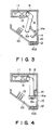
- Figure 2 is a sectional view of an ink jet recording apparatus according to an embodiment of the present invention.
- Figures 3 and 4 are sectional views illustrating rotational motion of the recording head according to the embodiment of the present invention.
- Figure 5 shows a positioning member used when the cartridge is mounted into the main assembly of the recording apparatus.
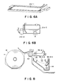
- Figures 6A and 6B illustrate an ink jet recording head and an ink supply system.
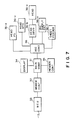
- Figure 7 is a block diagram of a facsimile machine according to an embodiment of the present invention.
- Figure 8 is a sectional view of an ink jet recording means in a facsimile machine.
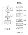
- Figure 9 is a flow chart illustrating the control operation of a main controller used in an embodiment of the present invention.
- Figure 10 is a flow chart illustrating the control operation of a record controller according to an embodiment of the present invention.
- Figure 11 is a sectional view of an ink jet apparatus according to a further embodiment of the present invention.
- Figure 12 is a sectional view of another example of a recording unit cartridge used with the apparatus of Figure 11, according to an embodiment of the present invention.
- a reference numeral 1 designates a rolled recording paper which is accommodated in a casing 2 of a main assembly of the recording apparatus.
- the recording apparatus comprises a recording paper guide 3 for confining the recording paper, a conveying roller 4 driven by an unshown driving means, a roller 5 mounted on a cover 7 of the main assembly together with a contact guide 6 of the recording paper guide 3.
- the roller 5 is urged to the conveying roller 4 through the recording paper, by which the recording paper can be fed.
- the recording paper guide 3 is close to or contacted to the conveying roller 4, so that the recording paper passage position is limited.
- a full-line ink jet recording head 8 is provided with ejection outlets for ejecting ink over the entire length (recording width), and each of the ejection outlets is provided with electrothermal transducer or energy generating element for generating energy contributable to the ejection of the ink.
- the recording head 9 is rotatably supported on a rotational shaft 9. In this Figure, the recording head 8 is shown as being positioned at its printing position. By ejection of ink droplets through the ejection outlets 8a to the recording paper so that a desired image is recorded on the recording paper.
- a cartridge detachably mountable to the main assembly is comprised of a casing 10, the recording head 8, the ink supply container 11, a residual ink receptor 12 having an ink absorbing material such as sponge, a wiping blade 13 for cleaning the ejection side surface of the fed and a cap 14 for contacting and capping an ejection side surface of the recording head during non-recording period and during the recording head recovery operation or the like.
- the casing covers these element as a unit.
- the blade 13 is made of elastic material such as silicone rubber, and it is hydrophilic to efficiently wipe the ejection side surface.
- the ejection side surface of the head is in contact with the blade 13 so as to be wiped.
- three blades 13 are provided. However, one blade may be enough, or more blades may be used. The number thereof is not limited if the ink can be satisfactorily wiped out from the ejection side surface.
- a cap 14 functions to seal the ink ejection outlets so as not to permit the recording head to be dried during the rest period of the apparatus.
- the cap 14 rotates about the center 14a in contact with a part of the recording head 8 and using the rotational motion of the recording head 8, by which it seals the ejection side surface of the recording head, as shown in Figure 3 (capped state).
- the cartridge 10 is detachable or mountable relative to the main assembly 2.
- the recording head 8, the ink container 11, the residual ink receptor 12, the wiping blade 13, the cap 14 and the like are replaced as a unit.
- the cartridge 10 does not have a driving source for the rotational movement of the head 8 in the cartridge. Therefore, the head driving source is disposed in the main apparatus and is operatively coupled with the cartridge 10 to transmit the driving force to the cartridge 10.
- the positioning is effected by aligning a guide 10a of the cartridge 10 and the corresponding guide (not shown) of the main assembly of the apparatus, by which the cartridge is correctly positioned relative to the main assembly. With this aligned state maintained, the cartridge is slid into the main assembly. By doing so, the cartridge falls to be set correctly, upon which the unshown driving gear of the cartridge and the drive transmission gear 9a are meshed to establish a driving correction therebetween.
- the gear meshing is utilized in this embodiment as a part of positioning members, by which the positioning accuracy upon the mounting of the cartridge is improved.
- the electric connection for the purpose of transmission of the image signals from the main assembly of the apparatus is also established.
- positioning members 4a may be provided at the opposite ends of the conveying roller 4 of the main assembly to be contacted to the corresponding positioning members (limiting members) 10b of the cartridge.
- a leaf spring or the like 17 may be used at a backside of the cartridge to urge the cartridge toward the positioning member 4a for the conveying roller, by which the accuracy is further improved.
- the cartridge 10 has a sensor for detecting a remaining amount of the ink 11, as indicated by a reference numeral 15 in Figure 2. It is of such a pipe that an electric resistance between electrodes is detected. Therefore, the timing of the cartridge 10 replacement is detected by the use-up of the ink.
- Various parts of the cartridge 10 are designed in consideration of the operable driving period of the recording head, the capacity of the residual ink receptor 12, durability of the cap 14 and the durability of the wiping blade or the like matched with the use-up of the ink contained.
- the recording head is positioned at the position shown in Figure 1 by an unshown recording head driving motor, and while the recording head 8 is stationary at this position, the recording operation is effected. At this time, the ink is supplied from the ink container disposed above the recording head 8.
- the position of the ink container is not limited to this, but may be different if the ink can be satisfactorily supplied to the recording head. It is possible to dispose it below the recording head.
- the supporting member for the recording head is bent, so that the position of the ejection outlets and the rotational shaft are deviated, as shown in Figure 1. Then, the ink passages having the electrothermal transducers in the recording head and the surface of the ink in the ink container 11 are maintained substantially parallel. Upon interruption or stop of the recording operation, the rotation of the motor is transmitted to the recording head so that the recording head 8 rotates downwardly from the recording position to the non-recording position.
- the blade 13 is fixed in the cartridge at such a position that it wipes the plural ejection outlets during the rotational movement, by which all of the ejection outlets are cleaned by rotation of the recording head through 10 - 80 degrees.
- the recording head 8 continues to rotate to reach a capping position where the cap 14 is disposed ( Figure 3 position, that is, capping position).
- Figure 3 position that is, capping position.
- the ink removed from the recording head by the above-described wiping action flows along the blade 13 and an inclined surface 101 on which the blades are mounted, into a residual ink container 12 disposed below the cap 14.
- the residual ink container 12 contains an ink absorbing material made of porous material to retain the residual ink.
- the cap 14 rotates about its supporting shaft by the rotational movement of the recording head and caps the ejection side of the recording head 8 when the ejection side surface faces down.
- the recording head 8, the ink container 11, the cap 14, the residual ink container 12 and the blade 13 are contained as a unit in the cartridge. Therefore, it can be replaced without difficulty and without liability of the introduction of the foreign matter. Thus, the expertise is not required for the maintenance. Thus, the ordinary use can effect the maintenance operation without difficulty.
- the recording head is moved away from the recording surface (recording position) by the rotational motion, and is returned to the recording position by the reverse rotation from the capping position, by which the driving system for the recording head is simplified, and the cost of the cartridge can be reduced.
- the fundamental structure and the sequential operations of the apparatus of this embodiment are the same as the first embodiment, but it is different from the first embodiment in that the recording head is disposed in the main assembly, and the ink container, the blade, the cap and the residual ink receptor are in the cartridge detachably mountable to the main assembly. By doing so, the cost of the cartridge is further reduced. In addition, the mechanism for the correct positioning of the recording head can be omitted, by which the easiness of the replacement operation is enhanced.
- the specific structure of the main assembly (rolled paper, driving roller or the like), the positioning of the parts in the cartridge and the like are not limiting.
- FIG. 6A and 6B there is shown an example of a line recording ink jet head.
- a large number of ink ejection outlets are distributed over the entire recording width.
- the ink is supplied through the ink supply passage 21a-1.
- Ink ejecting means (heater or the like not shown) is provided for each of the ejection outlets is controlled to effect the line recording, thus increasing the printing speed and the printing quality.
- Peculiar to the ink jet recording there is a liability of improper printing attributable to evaporation, drying, leakage or the like of the ink, contamination thereby, contamination by foreign matter, production of bubble in the ink supply passage or the like.
- a head recovery operation is desired in the printing intervals or in the rest period by idle ejections through all of the ejection outlets of the head or by filling the head with the ink or the like.
- the ejection outlets of the head are sealed by a capping mechanism.
- FIG. 7 is a block diagram of a facsimile machine according to an embodiment of the present invention. It comprises a main controller 31 to control the facsimile operations such as reading, recording, communication or the like, a modem controller 32 connected with a telephone line through NCU 33, an operation and display panel 34 including LCD and LED key switches, and a reader controller including CCD or contact sensor.
- a controller 36 effects a control operation for recording the image read by the reader 35 or the image received by the modem controller 32.
- the printing operation is started by actuating a driving circuit 36-a for the data transferred to the head 36-a.
- a motor 36-c moves the head to a rest position, a recovery position, a printing position or the like.
- a position detecting sensor 36-d detects the position of the head.
- a circuit 36-e is provided to effect the ink supply to the line head. The ink supply operation is carried out after replacement of the ink cartridge or upon the recovery operation for the head.
- a motor 36-f is a line
- Figure 8 is a sectional view of an ink jet recording device according to the embodiment of the present invention.
- Recording paper is designed by a reference numeral 41. It comprises a recording paper feeding platen roller 42, an ink jet head maintaining cap 43 and a residual ink tray 44. It further comprises a printing position sensor 36d-1, a recovery position sensor 36d-2 and a rest position sensor 36d-3, and a blade 45.
- the ink jet head of Figure 6A is a full-line type ink jet head wherein the number of ejection outlets covering the entire length of one recording line.
- the ink supply pipe 36a-1 is used to supply the ink from the ink container by a gear pump.
- the description will be made as to the operation at the stop position of the recording head.
- the recording head is at the printing position, in which the head driving circuit 36-b is actuated to effect the recording.
- the sensor 36d-2 is actuated, the head is at the head recovery position in which in order for the recovery from the improper printing attributable to the clogging of the nozzle or the ink evaporation, the ink supply operation (36-e) or the idle ejection (36-b) (solid black image).
- the ink ejected is received by the residual ink tray.
- the sensor 36d-3 is actuated, the head is at the rest position in which the head is capped for the purpose of prevention of the ink evaporation and the prevention of the clogging during the non-use of the head.
- Designated by a reference 36a-2 is a gear pump for supplying the ink to the head from the ink cartridge 36a-3.
- the pump By actuating the ink filling circuit 36-e in Figure 5, the pump is driven to supply the ink.
- the recovery operation includes a method in which the ink is supplied by the pump and a method in which all black information is supplied to the recording head, and the head driver circuit 36-b' of Figure 7 is actuated to effect the solid black printing while the recording head at the recovery position.
- the ejection side surface of the recording head is wiped by the blade 45, so that the residual ink adjacent the ejection outlets are removed.
- Figure 9 is a flow chart of the operation of the main controller
- Figure 10 is a flow chart of the operation of the record controller.
- FIG 9 is the flow chart of the operation of the main controller during the regular recovery operations.
- the discrimination is made as to whether the time T in the display circuit is equal to the predetermined time a .
- a step S3 is executed to produce instructions for the regular recovery operation to the record controller, and the flow of the sequence returns to the step S1.
- Figure 10 shows the flow chart of the operation of the record controller upon receiving the regular recovery instructions.
- the head moving motor 36c is driven until the sensor 36d-3 is actuated, that is, until the head reaches the recovery position.
- the recovery operation described hereinbefore is carried out.
- the head moving motor 36c is driven through move the recording head from the recovery position to move in contact with the blade 45 and to return.
- the head is moved to the rest position where it is capped, and the sensor 36d-3 is actuated. This is the end of the regular recovery operation.
- a water absorbing sponge material or roller is usable.
- the capping means may be equipped with a driving means therefor.
- the cleaning position, the recovery position, the rest position and the printing position may be changed in their relative positional relation.
- the record controller may contain the time counting function to effect its control. Other various modification is possible within the scope of the present invention.
- the facsimile machine is usable with a cut sheet.
- the recording head, the cap, the blade, the ink supply container and the residual ink container are contained as a unit in a cartridge.
- the cartridge is detachably mountable into the recording apparatus.
- Figure 11 shows a general arrangement of the facsimile machine 51. It comprises an image reader 52, a recording material container 54, a cartridge 53, an image fixing station 55, a recording sheet discharging station 56, a recording sheet conveying portion 57 and the like.
- the image reader 52 is provided with an original feeding system (not shown) which feeds an original from an original tray 52a to an original discharge tray 52b, and during the feeding, a sensor of the reader 52 reads the original, and the read information is transmitted.
- an original feeding system not shown
- the image received thereby is recorded on a recording sheet 54a conveyed from the recording sheet supply tray 54 to the recording station by a feeding roller 57.
- the image thus recorded is fixed in the fixing station 55, and the sheet is discharged to the discharge tray 56.
- the recording sheet supply tray 54 is exchangeable when a cover 51b provided in a side of the apparatus 51 is opened in a direction indicated by an arrow.
- a cartridge 53 which is detachably mountable into the recording apparatus comprises a unit an ink cartridge 62 having a recording head 61, a cap 65, an ink supply container and a discharge ink container, an ink supply cube 63 for supplying the ink to the head 61, a residual ink cube 66 connected with the cap 65, and a blade 64 for cleaning the ejection side surface of the head 61.
- the cartridge 53 is mounted to or dismounted from the main assembly of the apparatus 51 when the cover 51a formed in a part of a side wall of the apparatus 51.
- the structure of the first embodiment is usable.
- the cartridge 53 of this embodiment is also equipped with a driving system (not shown).
- the driving system By the driving system, the recording head 61 is movable between a recording position indicated by a broken line and a non-recording position faced to the cap 65, indicated by the solid line.
- the cartridge is provided with a shutter 53b at the recording position of the head 61, the shutter 53b being opened while it is mounted in the apparatus.
- a blade 64 for cleaning the ejection side surface of the head.
- the blade 64 accomplishes the cleaning by the rotation thereof while the recording head is retained at the cleaning position.
- the rotational direction may be either, but if it is clockwise direction in the Figure, the recording region is prevented from contamination by ink mist upon the cleaning operation. If it is counterclockwise, a blocking wall may be used for the protection from the ink mist.
- An ink absorbing material contactable to the cleaning surface of the blade may be disposed in the rotational path of the blade 64.
- the cap 65 at the non-recording position is mounted to a rib 53a projected from the cartridge casing to cover the ejection side surface of the recording head. The cap is urged toward the head by a spring member 65a to buffer the impact of contact upon covering the head and to ensure the capping.
- the ink cartridge 62 comprises an ink container 62a containing the ink to be supplied to the head 61 through the ink supply cube 63 and a residual ink container 62b for accommodating the ink discharged from the head 61 into the cap 65 by idle ejection, through an ink collecting tube 66, as a unit.
- the ink cartridge 60 is detachably mountable to the cartridge 53. It is joined with the ink supply tube 63 and the ink collecting tube 66 by a joint 67 to establish the ink supply to the head 61 and the ink collection from the cap 65.
- the consideration is made to the case in which the quantity of the ink in the ink container is relatively small as compared with the service life of the recording head, and therefore, even if the ink in the container is used up, the recording head is still usable. Accordingly, only the ink container 62 is replaceable upon use-up of the ink.
- the cartridge 53 is removed from the main assembly of the recording apparatus, and another cartridge is mounted thereinto. In this manner, the maintenance is easy. It is the fact that the connection of the ink passage, for example, the fitting between the head and the ink supply tube or the fitting between the cap and the ink collection tube, is difficult, and in addition, it is possible that the apparatus is contaminated with the ink, or the operator's hand is contaminated thereby during the maintenance operation. Therefore, the cartridge structure of this embodiment is desirable.
- the element such as the recording head having a relatively long service life and an element having a relatively shorter service life, can be separately replaceable, by which the long life element is effectively used.
- the cartridge 53 contains all the system containing the ink and is separate from the other unit by the cartridge casing. Therefore, it does not easily accept the foreign matter such as paper dust produced from the recording paper or the dust in the apparatus, so that the ejection side surface of the recording head, the capping member and the blade are effectively protected; even if the ink is leaked, the leaked ink does not influence the other unit or units; and upon malfunction of the ink supply system, the maintenance is easy since it includes only the replacement of the cartridge, the maintenance operation otherwise having been difficult.
- the unit may contained an original reader system and a recording system for recording an image received thereby.
- the unit is easily replaced, as desired.
- the easy maintenance is similarly accomplished by constructing as a unit the image reading system and constructing as a unit the recording system.
- the unit structure is not limited to these two examples.
- a sheet feeding system in the recording system, the ink (image) fixing system may be constituted as the respective units or as a unit to further facilitate the maintenance operation.
- a plurality of feeding system units may be of different types, for example, one for cut sheets and another for rolled paper.
- the fixing system is constituted as a unit, the fixing system may correspond to the used recording material.
- the recording unit cartridge may be of the full-line type or a serial type or a multi-color recording head type (the driving system for the head is desirably provided in the cartridge for the purpose of simplified structure).
- the present invention is particularly suitably usable in a bubble jet recording head and recording apparatus developed by Canon Kabushiki Kaisha, Japan. This is because, the high density of the picture element, and the high resolution of the recording are possible.
- the principle is applicable to a so-called on-demand type recording system and a continuous type recording system particularly however, it is suitable for the on-demand type because the principle is such that at least one driving signal is applied to an electrothermal transducer disposed on a liquid (ink) retaining sheet or liquid passage, the driving signal being enough to provide such a quick temperature rise beyond a departure from nucleation boiling point, by which the thermal energy is provide by the electrothermal transducer to produce film boiling on the heating portion of the recording head, whereby a bubble can be formed in the liquid (ink) corresponding to each of the driving signals.
- the liquid (ink) is ejected through an ejection outlet to produce at least one droplet.
- the driving signal is preferably in the form of a pulse, because the development and collapse of the bubble can be effected instantaneously, and therefore, the liquid (ink) is ejected with quick response.
- the driving signal in the form of the pulse is preferably such as disclosed in U.S. Patents Nos. 4,463,359 and 4,345,262.
- the temperature increasing rate of the heating surface is preferably such as disclosed in U.S. Patent No. 4,313,124.
- the structure of the recording head may be as shown in U.S. Patent Nos. 4,558,333 and 4,459,600 wherein the heating portion is disposed at a bent portion in addition to the structure of the combination of the ejection outlet, liquid passage and the electrothermal transducer as disclosed in the above-mentioned patents.
- the present invention is applicable to the structure disclosed in Japanese Laid-Open Patent Application Publication No. 123670/1984 wherein a common slit is used as the ejection outlet for plural electrothermal transducers, and to the structure disclosed in Japanese Laid-Open Patent Application No. 138461/1984 wherein an opening for absorbing pressure wave of the thermal energy is formed corresponding to the ejecting portion. This is because, the present invention is effective to perform the recording operation with certainty and at high efficiency irrespective of the type of the recording head.
- the present invention is effectively applicable to a so-called full-line type recording head having a length corresponding to the maximum recording width.
- a recording head may comprise a single recording head and a plural recording head combined to cover the entire width.
- the present invention is applicable to a serial type recording head wherein the recording head is fixed on the main assembly, to a replaceable chip type recording head which is connected electrically with the main apparatus and can be supplied with the ink by being mounted in the main assembly, or to a cartridge type recording head having an integral ink container.
- the recovery means and the auxiliary means for the preliminary operation are preferable, because they can further stabilize the effect of the present invention.
- the recording head mountable it may be a single corresponding to a single color ink, or may be plural corresponding to the plurality of ink materials having different recording color or density.
- the present invention is effectively applicable to an apparatus having at least one of a monochromatic mode mainly with black and a multi-color with different color ink materials and a full-color mode by the mixture of the colors which may be an integrally formed recording unit or a combination of plural recording heads.
- the ink has been liquid. It may be, however, an ink material solidified at the room temperature or below and liquefied at the room temperature. Since in the ink jet recording system, the ink is controlled within the temperature not less than 30 °C and not more than 70 °C to stabilize the viscosity of the ink to provide the stabilized ejection, in usual recording apparatus of this type, the ink is such that it is liquid within the temperature range when the recording signal is applied. In addition, the temperature rise due to the thermal energy is positively prevented by consuming it for the state change of the ink from the solid state to the liquid state, or the ink material is solidified when it is left is used to prevent the evaporation of the ink.
- the ink may be liquefied, and the liquefied ink may be ejected.
- the ink may start to be solidified at the time when it reaches the recording material.
- the present invention is applicable to such an ink material as is liquefied by the application of the thermal energy.
- Such an ink material may be retained as a liquid or solid material on through holes or recesses formed in a porous sheet as disclosed in Japanese Laid-Open Patent Application No. 56847/1979 and Japanese Laid-Open Patent Application No. 71260/1985.
- the sheet is faced to the electrothermal transducers.
- the most effective one for the ink materials described above is the film boiling system.
- the ink jet recording apparatus may be used as an output terminal of an information processing apparatus such as computer or the like, a copying apparatus combined with an image reader or the like, or a facsimile machine having information sending and receiving functions.
- an information processing apparatus such as computer or the like
- a copying apparatus combined with an image reader or the like or a facsimile machine having information sending and receiving functions.
- a recording unit cartridge includes as a unit: a recording head for ejecting ink to effect recording; an ink supply system for supplying the ink to the recording head; a capping member for covering an ink ejection side surface of the recording head; an ink collecting member the ink discharged to recover the recording head and not used for the recording; a cleaning member for cleaning the ink ejection side surface of the recording head; and a casing for containing as a unit the head system and members, wherein the unit cartridge is detachably mountable to a main assembly of a recording apparatus.
Abstract
Description
- The present invention relates to an ink jet recording apparatus and a recording unit cartridge wherein a desired image is formed by ejection of ink.
- As shown in Figure 1, an ink jet apparatus comprises a
recording head 101 having an ejection outlet for ejecting ink, anink container 101 for containing ink ejected from thehead 101, a pipe 103 (ink supply pipe) for supplying the ink from thecontainer 102 to thehead 101, apump 104 for the ink supply or for filling the head with the ink at the initial stage, anink receptor 105 for receiving the ink not used for the recording or acap member 105 for contacting the ejection side surface of thehead 101 to protect it or to recover the ejection of the ink from the head, apump 107 for collecting the ink not used, aresidual ink container 106 and a controller for controlling them. When theink container 102 becomes empty by consumption of the ink for the recording, theink container 102 is replaced with a fresh container, so that the recording operation can be continued. If, however, when therecording head 101 is damaged or warn to be not usable for the good recording operation, therecording head 101 is removed from thepipe 103, and is replaced with a fresh recording head, by which the recording operation can be continued. If the quantity of the ink in the residual ink container increases beyond its capacity, theresidual ink container 106 is replaced with an empty one, by which the contamination of the apparatus attributable to the overflow of the residual ink can be prevented. In the apparatus, the replacements have been possible for the respective constituent parts to maintain the quality of the recorded images. - The apparatus in which the parts are replaceable, is advantageous in that the good operation of the system can be maintained simply by replacing only the part to be replaced. However, such an apparatus involves the following problems.
- (1) Since the number of the parts is large, large spaces and expertise is required and the cost of the entire apparatus is high.
- (2) Since it has many connections between constituent parts, the ink may leak from the connecting portion or portions due to vibration or inclination during the apparatus being carried. If this occurs, the inside of the apparatus may be contaminated. The high positioning accuracy is required among the constituent parts such as the recording head, a platen roller, the capping member, a cleaning member for cleaning the ejection side surface of the head, the ink container and the residual ink container. The high accuracy is required because the ink is used for the recording. In order to take great care to prevent introduction of foreign matter such as dust during the replacing operation, and therefore, the maintenance operation is time consuming.
- It will be understood that these problems are particularly noted when a simple and low cost apparatus is considered.
- Accordingly, it is a principal object of the present invention to provide an ink jet apparatus the recording head, the ink container, the residual ink container or the like (consumable part) are easily replaceable without the liability of introduction of the foreign matter or without the necessity for the high accuracy positioning, by which the stabilized and ensured recording operations are maintained with a simple structure and at a low cost.
- It is another object of the present invention to provide an ink jet recording apparatus wherein the recovery and protection of the recording head can be assured without the liability of the introduction of the foreign matter, by which the recording operation is maintained.
- According to an aspect of the present invention, there is provided a recording unit cartridge, comprising as a unit: a recording head for ejecting ink to effect recording; an ink supply system for supplying the ink to said recording head; a capping member for covering an ink ejection side surface of said recording head; an ink collecting member the ink discharged to recover said recording head and not used for the recording; a cleaning member for cleaning the ink ejection side surface of said recording head; and a casing for containing as a unit said head system and members, wherein said unit cartridge is detachably mountable to a main assembly of a recording apparatus.
- According to another aspect of the present invention, there is provided an ink jet apparatus, comprising: a recording unit cartridge, comprising as a unit: a recording head for ejecting ink to effect recording; an ink supply system for supplying the ink to said recording head; a capping member for covering an ink ejection side surface of said recording head; an ink collecting member the ink discharged to recover said recording head and not used for the recording; a cleaning member for cleaning the ink ejection side surface of said recording head; a casing for containing as a unit said head system and members, wherein said unit cartridge is detachably mountable to a main assembly of a recording apparatus; and a mount for detachably mounting said cartridge and having a driving system for moving the recording head in said cartridge when the cartridge is mounted on said mount.
- These and other objects, features and advantages of the present invention will become more apparent upon a consideration of the following description of the preferred embodiments of the present invention taken in conjunction with the accompanying drawings.
- Figure 1 shows a conventional ink jet apparatus.
- Figure 2 is a sectional view of an ink jet recording apparatus according to an embodiment of the present invention.
- Figures 3 and 4 are sectional views illustrating rotational motion of the recording head according to the embodiment of the present invention.
- Figure 5 shows a positioning member used when the cartridge is mounted into the main assembly of the recording apparatus.
- Figures 6A and 6B illustrate an ink jet recording head and an ink supply system.
- Figure 7 is a block diagram of a facsimile machine according to an embodiment of the present invention.
- Figure 8 is a sectional view of an ink jet recording means in a facsimile machine.
- Figure 9 is a flow chart illustrating the control operation of a main controller used in an embodiment of the present invention.
- Figure 10 is a flow chart illustrating the control operation of a record controller according to an embodiment of the present invention.
- Figure 11 is a sectional view of an ink jet apparatus according to a further embodiment of the present invention.
- Figure 12 is a sectional view of another example of a recording unit cartridge used with the apparatus of Figure 11, according to an embodiment of the present invention.
- Referring to Figure 2, there is shown an ink jet recording apparatus according to a first embodiment of the present invention. In this Figure which is a sectional view, a reference numeral 1 designates a rolled recording paper which is accommodated in a
casing 2 of a main assembly of the recording apparatus. The recording apparatus comprises arecording paper guide 3 for confining the recording paper, aconveying roller 4 driven by an unshown driving means, aroller 5 mounted on acover 7 of the main assembly together with acontact guide 6 of therecording paper guide 3. Upon operation under the state shown in the Figure, theroller 5 is urged to theconveying roller 4 through the recording paper, by which the recording paper can be fed. Therecording paper guide 3 is close to or contacted to theconveying roller 4, so that the recording paper passage position is limited. A full-line inkjet recording head 8 is provided with ejection outlets for ejecting ink over the entire length (recording width), and each of the ejection outlets is provided with electrothermal transducer or energy generating element for generating energy contributable to the ejection of the ink. Therecording head 9 is rotatably supported on arotational shaft 9. In this Figure, therecording head 8 is shown as being positioned at its printing position. By ejection of ink droplets through theejection outlets 8a to the recording paper so that a desired image is recorded on the recording paper. The position of the line recording effected is selected to be slightly below an end of thecontact guide 6 so that the recording paper is stably passed, by which the printing quality is assured. A cartridge detachably mountable to the main assembly is comprised of acasing 10, therecording head 8, theink supply container 11, aresidual ink receptor 12 having an ink absorbing material such as sponge, awiping blade 13 for cleaning the ejection side surface of the fed and acap 14 for contacting and capping an ejection side surface of the recording head during non-recording period and during the recording head recovery operation or the like. The casing covers these element as a unit. Theblade 13 is made of elastic material such as silicone rubber, and it is hydrophilic to efficiently wipe the ejection side surface. When therecording head 8 rotates about theshaft 9 between its recording position and non-recording position, the ejection side surface of the head is in contact with theblade 13 so as to be wiped. In this Figure, threeblades 13 are provided. However, one blade may be enough, or more blades may be used. The number thereof is not limited if the ink can be satisfactorily wiped out from the ejection side surface. Acap 14 functions to seal the ink ejection outlets so as not to permit the recording head to be dried during the rest period of the apparatus. As shown in Figures 2 and 3, thecap 14 rotates about thecenter 14a in contact with a part of therecording head 8 and using the rotational motion of therecording head 8, by which it seals the ejection side surface of the recording head, as shown in Figure 3 (capped state). - When the
cover 7 of the main assembly is opened from themain assembly 2, thecartridge 10 is detachable or mountable relative to themain assembly 2. In this embodiment, therefore, therecording head 8, theink container 11, theresidual ink receptor 12, thewiping blade 13, thecap 14 and the like are replaced as a unit. - From the standpoint of simplifying the structure, the
cartridge 10 does not have a driving source for the rotational movement of thehead 8 in the cartridge. Therefore, the head driving source is disposed in the main apparatus and is operatively coupled with thecartridge 10 to transmit the driving force to thecartridge 10. - More particularly, as shown in Figure 5, the positioning is effected by aligning a
guide 10a of thecartridge 10 and the corresponding guide (not shown) of the main assembly of the apparatus, by which the cartridge is correctly positioned relative to the main assembly. With this aligned state maintained, the cartridge is slid into the main assembly. By doing so, the cartridge falls to be set correctly, upon which the unshown driving gear of the cartridge and thedrive transmission gear 9a are meshed to establish a driving correction therebetween. The gear meshing is utilized in this embodiment as a part of positioning members, by which the positioning accuracy upon the mounting of the cartridge is improved. In addition, the electric connection for the purpose of transmission of the image signals from the main assembly of the apparatus, is also established. - The positioning between the main assembly and the
cartridge 10 is accomplished by aguide 10a. Another structure is usable if the correct positioning is accomplished. In order to improve the accuracy of the clearance between thehead 8 and the platen (conveying)roller 4, that is, the head-paper clearance,positioning members 4a may be provided at the opposite ends of the conveyingroller 4 of the main assembly to be contacted to the corresponding positioning members (limiting members) 10b of the cartridge. At this time, a leaf spring or the like 17 may be used at a backside of the cartridge to urge the cartridge toward the positioningmember 4a for the conveying roller, by which the accuracy is further improved. - In this embodiment, the
cartridge 10 has a sensor for detecting a remaining amount of theink 11, as indicated by areference numeral 15 in Figure 2. It is of such a pipe that an electric resistance between electrodes is detected. Therefore, the timing of thecartridge 10 replacement is detected by the use-up of the ink. Various parts of thecartridge 10 are designed in consideration of the operable driving period of the recording head, the capacity of theresidual ink receptor 12, durability of thecap 14 and the durability of the wiping blade or the like matched with the use-up of the ink contained. - The description will be further made as to the cartridge.
- The recording head is positioned at the position shown in Figure 1 by an unshown recording head driving motor, and while the
recording head 8 is stationary at this position, the recording operation is effected. At this time, the ink is supplied from the ink container disposed above therecording head 8. The position of the ink container is not limited to this, but may be different if the ink can be satisfactorily supplied to the recording head. It is possible to dispose it below the recording head. - In order to stabilize the ink supply at this time, the supporting member for the recording head is bent, so that the position of the ejection outlets and the rotational shaft are deviated, as shown in Figure 1. Then, the ink passages having the electrothermal transducers in the recording head and the surface of the ink in the
ink container 11 are maintained substantially parallel. Upon interruption or stop of the recording operation, the rotation of the motor is transmitted to the recording head so that therecording head 8 rotates downwardly from the recording position to the non-recording position. Theblade 13 is fixed in the cartridge at such a position that it wipes the plural ejection outlets during the rotational movement, by which all of the ejection outlets are cleaned by rotation of the recording head through 10 - 80 degrees. After the cleaning, therecording head 8 continues to rotate to reach a capping position where thecap 14 is disposed (Figure 3 position, that is, capping position). At this time, the ink removed from the recording head by the above-described wiping action flows along theblade 13 and aninclined surface 101 on which the blades are mounted, into aresidual ink container 12 disposed below thecap 14. - The
residual ink container 12 contains an ink absorbing material made of porous material to retain the residual ink. - The
cap 14 rotates about its supporting shaft by the rotational movement of the recording head and caps the ejection side of therecording head 8 when the ejection side surface faces down. - As described in the foregoing, according to this embodiment, the
recording head 8, theink container 11, thecap 14, theresidual ink container 12 and theblade 13 are contained as a unit in the cartridge. Therefore, it can be replaced without difficulty and without liability of the introduction of the foreign matter. Thus, the expertise is not required for the maintenance. Thus, the ordinary use can effect the maintenance operation without difficulty. In addition, since the recording head is moved away from the recording surface (recording position) by the rotational motion, and is returned to the recording position by the reverse rotation from the capping position, by which the driving system for the recording head is simplified, and the cost of the cartridge can be reduced. - The fundamental structure and the sequential operations of the apparatus of this embodiment are the same as the first embodiment, but it is different from the first embodiment in that the recording head is disposed in the main assembly, and the ink container, the blade, the cap and the residual ink receptor are in the cartridge detachably mountable to the main assembly. By doing so, the cost of the cartridge is further reduced. In addition, the mechanism for the correct positioning of the recording head can be omitted, by which the easiness of the replacement operation is enhanced.
- In the present invention, the specific structure of the main assembly (rolled paper, driving roller or the like), the positioning of the parts in the cartridge and the like are not limiting.
- According to the embodiments described in the foregoing, the following advantageous effects are provided.
- (1) The constituent elements of the ink supply system of an ink jet recording apparatus are all contained in a cartridge as a unit, and therefore, the liability of introduction of the foreign matter into the ink supply system is eliminated; the liability of the ink leakage is reduced; the leaked ink, if any, is confined within the cartridge without liability of influence to the main apparatus. The ink supply system can be arranged in a small space.
- (2) During cleaning and repairing operation for the leaked ink due to a trouble in the supply system, the liability of an additional trouble by the ink can be eliminated, thus achieving an easy maintenance because of the replacement of the cartridge as a whole.
- (3) By matching the service life of substantially all of the functional elements with the amount of the ink contained, the parts around the ink can be reasonably designed to reduce the manufacturing cost.
- (4) The manufacturing plant may be divided into a part manufacturing the main assembly and a part manufacturing the cartridge, by which the manufacturing lines may be classified depending on the presence or absence of the ink, so that the manufacturing cost can be reasonably reduced, and the productivity can be improved, and in addition, the inspection steps can be simplified.
- Referring to Figures 6A and 6B, there is shown an example of a line recording ink jet head. As will be understood, a large number of ink ejection outlets are distributed over the entire recording width. The ink is supplied through the
ink supply passage 21a-1. Ink ejecting means (heater or the like not shown) is provided for each of the ejection outlets is controlled to effect the line recording, thus increasing the printing speed and the printing quality. - Peculiar to the ink jet recording, there is a liability of improper printing attributable to evaporation, drying, leakage or the like of the ink, contamination thereby, contamination by foreign matter, production of bubble in the ink supply passage or the like. In order to prevent the occurrence of the improper printing, a head recovery operation is desired in the printing intervals or in the rest period by idle ejections through all of the ejection outlets of the head or by filling the head with the ink or the like. Also, it is desired that the ejection outlets of the head are sealed by a capping mechanism. These are effective to eliminate the liability of improper recording particularly after a long rest period.
- Figure 7 is a block diagram of a facsimile machine according to an embodiment of the present invention. It comprises a
main controller 31 to control the facsimile operations such as reading, recording, communication or the like, amodem controller 32 connected with a telephone line throughNCU 33, an operation anddisplay panel 34 including LCD and LED key switches, and a reader controller including CCD or contact sensor. Acontroller 36 effects a control operation for recording the image read by thereader 35 or the image received by themodem controller 32. The printing operation is started by actuating a driving circuit 36-a for the data transferred to the head 36-a. A motor 36-c moves the head to a rest position, a recovery position, a printing position or the like. A position detecting sensor 36-d detects the position of the head. A circuit 36-e is provided to effect the ink supply to the line head. The ink supply operation is carried out after replacement of the ink cartridge or upon the recovery operation for the head. A motor 36-f is a line feed motor for feeding the recording paper line by line. - Figure 8 is a sectional view of an ink jet recording device according to the embodiment of the present invention. Recording paper is designed by a
reference numeral 41. It comprises a recording paper feedingplaten roller 42, an ink jethead maintaining cap 43 and aresidual ink tray 44. It further comprises a printing position sensor 36d-1, a recovery position sensor 36d-2 and a rest position sensor 36d-3, and ablade 45. The ink jet head of Figure 6A is a full-line type ink jet head wherein the number of ejection outlets covering the entire length of one recording line. The ink supply pipe 36a-1 is used to supply the ink from the ink container by a gear pump. - The description will be made as to the operation at the stop position of the recording head. When the sensor 36d-1 in Figure 8 is actuated, the recording head is at the printing position, in which the head driving circuit 36-b is actuated to effect the recording. When the sensor 36d-2 is actuated, the head is at the head recovery position in which in order for the recovery from the improper printing attributable to the clogging of the nozzle or the ink evaporation, the ink supply operation (36-e) or the idle ejection (36-b) (solid black image). The ink ejected is received by the residual ink tray. When the sensor 36d-3 is actuated, the head is at the rest position in which the head is capped for the purpose of prevention of the ink evaporation and the prevention of the clogging during the non-use of the head.
- Designated by a reference 36a-2 is a gear pump for supplying the ink to the head from the ink cartridge 36a-3. By actuating the ink filling circuit 36-e in Figure 5, the pump is driven to supply the ink. The recovery operation includes a method in which the ink is supplied by the pump and a method in which all black information is supplied to the recording head, and the head driver circuit 36-b' of Figure 7 is actuated to effect the solid black printing while the recording head at the recovery position. In addition, during the head movement, the ejection side surface of the recording head is wiped by the
blade 45, so that the residual ink adjacent the ejection outlets are removed. - Referring to Figures 9 and 10, the operation will be described; Figure 9 is a flow chart of the operation of the main controller; and Figure 10 is a flow chart of the operation of the record controller.
- Figure 9 is the flow chart of the operation of the main controller during the regular recovery operations. At step S1, the discrimination is made as to whether the time T in the display circuit is equal to the predetermined time a. The time is expressed by CD minutes past AB o'clock (24 hours expression). Assuming that the recovery operation is carried out every 10 minutes, then D is selected for the time a (D = 0). If the recovery operation is carried out every 30 minutes, then CD is selected for the time a (C = 0 or 3, and D = 0). When T = a is satisfied, a step S2 is executed. When the capping position of the recording head is discriminated by the on-off detection by the sensor 36d-3, a step S3 is executed to produce instructions for the regular recovery operation to the record controller, and the flow of the sequence returns to the step S1.
- Figure 10 shows the flow chart of the operation of the record controller upon receiving the regular recovery instructions. At step S11, the head moving motor 36c is driven until the sensor 36d-3 is actuated, that is, until the head reaches the recovery position. At step S12, the recovery operation described hereinbefore is carried out. At step S13, the head moving motor 36c is driven through move the recording head from the recovery position to move in contact with the
blade 45 and to return. Subsequently, at step S14, the head is moved to the rest position where it is capped, and the sensor 36d-3 is actuated. This is the end of the regular recovery operation. - In place of the wiping blade, a water absorbing sponge material or roller is usable. The capping means may be equipped with a driving means therefor. The cleaning position, the recovery position, the rest position and the printing position may be changed in their relative positional relation. The record controller may contain the time counting function to effect its control. Other various modification is possible within the scope of the present invention.
- In this embodiment, the facsimile machine is usable with a cut sheet. The recording head, the cap, the blade, the ink supply container and the residual ink container are contained as a unit in a cartridge. The cartridge is detachably mountable into the recording apparatus.
- Figure 11 shows a general arrangement of the
facsimile machine 51. It comprises animage reader 52, arecording material container 54, acartridge 53, animage fixing station 55, a recordingsheet discharging station 56, a recording sheet conveying portion 57 and the like. - The
image reader 52 is provided with an original feeding system (not shown) which feeds an original from anoriginal tray 52a to anoriginal discharge tray 52b, and during the feeding, a sensor of thereader 52 reads the original, and the read information is transmitted. - The image received thereby is recorded on a
recording sheet 54a conveyed from the recordingsheet supply tray 54 to the recording station by a feeding roller 57. The image thus recorded is fixed in the fixingstation 55, and the sheet is discharged to thedischarge tray 56. - The recording
sheet supply tray 54 is exchangeable when a cover 51b provided in a side of theapparatus 51 is opened in a direction indicated by an arrow. - A
cartridge 53 which is detachably mountable into the recording apparatus comprises a unit anink cartridge 62 having arecording head 61, acap 65, an ink supply container and a discharge ink container, anink supply cube 63 for supplying the ink to thehead 61, aresidual ink cube 66 connected with thecap 65, and ablade 64 for cleaning the ejection side surface of thehead 61. Thecartridge 53 is mounted to or dismounted from the main assembly of theapparatus 51 when the cover 51a formed in a part of a side wall of theapparatus 51. As for the positioning mechanism upon the mounting or dismounting operation, the structure of the first embodiment is usable. - As shown in Figure 12, the
cartridge 53 of this embodiment is also equipped with a driving system (not shown). By the driving system, therecording head 61 is movable between a recording position indicated by a broken line and a non-recording position faced to thecap 65, indicated by the solid line. The cartridge is provided with ashutter 53b at the recording position of thehead 61, theshutter 53b being opened while it is mounted in the apparatus. - In the movement path of the recording head, there is a
blade 64 for cleaning the ejection side surface of the head. Theblade 64 accomplishes the cleaning by the rotation thereof while the recording head is retained at the cleaning position. The rotational direction may be either, but if it is clockwise direction in the Figure, the recording region is prevented from contamination by ink mist upon the cleaning operation. If it is counterclockwise, a blocking wall may be used for the protection from the ink mist. An ink absorbing material contactable to the cleaning surface of the blade may be disposed in the rotational path of theblade 64. Thecap 65 at the non-recording position is mounted to arib 53a projected from the cartridge casing to cover the ejection side surface of the recording head. The cap is urged toward the head by aspring member 65a to buffer the impact of contact upon covering the head and to ensure the capping. - In the
cartridge 53, there is anink cartridge 62. Theink cartridge 62 comprises anink container 62a containing the ink to be supplied to thehead 61 through theink supply cube 63 and aresidual ink container 62b for accommodating the ink discharged from thehead 61 into thecap 65 by idle ejection, through anink collecting tube 66, as a unit. - The ink cartridge 60 is detachably mountable to the
cartridge 53. It is joined with theink supply tube 63 and theink collecting tube 66 by a joint 67 to establish the ink supply to thehead 61 and the ink collection from thecap 65. - In this embodiment, the consideration is made to the case in which the quantity of the ink in the ink container is relatively small as compared with the service life of the recording head, and therefore, even if the ink in the container is used up, the recording head is still usable. Accordingly, only the
ink container 62 is replaceable upon use-up of the ink. - If the maintenance or service operation is required with respect to a part other than the
ink container 62, thecartridge 53 is removed from the main assembly of the recording apparatus, and another cartridge is mounted thereinto. In this manner, the maintenance is easy. It is the fact that the connection of the ink passage, for example, the fitting between the head and the ink supply tube or the fitting between the cap and the ink collection tube, is difficult, and in addition, it is possible that the apparatus is contaminated with the ink, or the operator's hand is contaminated thereby during the maintenance operation. Therefore, the cartridge structure of this embodiment is desirable. - According to this embodiment, the element such as the recording head having a relatively long service life and an element having a relatively shorter service life, can be separately replaceable, by which the long life element is effectively used.
- The
cartridge 53 contains all the system containing the ink and is separate from the other unit by the cartridge casing. Therefore, it does not easily accept the foreign matter such as paper dust produced from the recording paper or the dust in the apparatus, so that the ejection side surface of the recording head, the capping member and the blade are effectively protected; even if the ink is leaked, the leaked ink does not influence the other unit or units; and upon malfunction of the ink supply system, the maintenance is easy since it includes only the replacement of the cartridge, the maintenance operation otherwise having been difficult. - In addition, the unit may contained an original reader system and a recording system for recording an image received thereby. The unit is easily replaced, as desired. The easy maintenance is similarly accomplished by constructing as a unit the image reading system and constructing as a unit the recording system. The unit structure is not limited to these two examples. For example, a sheet feeding system in the recording system, the ink (image) fixing system may be constituted as the respective units or as a unit to further facilitate the maintenance operation. When the recording paper feeding system is replaceable, a plurality of feeding system units may be of different types, for example, one for cut sheets and another for rolled paper. When the fixing system is constituted as a unit, the fixing system may correspond to the used recording material. The recording unit cartridge may be of the full-line type or a serial type or a multi-color recording head type (the driving system for the head is desirably provided in the cartridge for the purpose of simplified structure).
- The present invention is particularly suitably usable in a bubble jet recording head and recording apparatus developed by Canon Kabushiki Kaisha, Japan. This is because, the high density of the picture element, and the high resolution of the recording are possible.
- The typical structure and the operational principle of preferably the one disclosed in U.S. Patent Nos. 4,723,129 and 4,740,796. The principle is applicable to a so-called on-demand type recording system and a continuous type recording system particularly however, it is suitable for the on-demand type because the principle is such that at least one driving signal is applied to an electrothermal transducer disposed on a liquid (ink) retaining sheet or liquid passage, the driving signal being enough to provide such a quick temperature rise beyond a departure from nucleation boiling point, by which the thermal energy is provide by the electrothermal transducer to produce film boiling on the heating portion of the recording head, whereby a bubble can be formed in the liquid (ink) corresponding to each of the driving signals. By the development and collapse of the the bubble, the liquid (ink) is ejected through an ejection outlet to produce at least one droplet. The driving signal is preferably in the form of a pulse, because the development and collapse of the bubble can be effected instantaneously, and therefore, the liquid (ink) is ejected with quick response. The driving signal in the form of the pulse is preferably such as disclosed in U.S. Patents Nos. 4,463,359 and 4,345,262. In addition, the temperature increasing rate of the heating surface is preferably such as disclosed in U.S. Patent No. 4,313,124.
- The structure of the recording head may be as shown in U.S. Patent Nos. 4,558,333 and 4,459,600 wherein the heating portion is disposed at a bent portion in addition to the structure of the combination of the ejection outlet, liquid passage and the electrothermal transducer as disclosed in the above-mentioned patents. In addition, the present invention is applicable to the structure disclosed in Japanese Laid-Open Patent Application Publication No. 123670/1984 wherein a common slit is used as the ejection outlet for plural electrothermal transducers, and to the structure disclosed in Japanese Laid-Open Patent Application No. 138461/1984 wherein an opening for absorbing pressure wave of the thermal energy is formed corresponding to the ejecting portion. This is because, the present invention is effective to perform the recording operation with certainty and at high efficiency irrespective of the type of the recording head.
- The present invention is effectively applicable to a so-called full-line type recording head having a length corresponding to the maximum recording width. Such a recording head may comprise a single recording head and a plural recording head combined to cover the entire width.
- In addition, the present invention is applicable to a serial type recording head wherein the recording head is fixed on the main assembly, to a replaceable chip type recording head which is connected electrically with the main apparatus and can be supplied with the ink by being mounted in the main assembly, or to a cartridge type recording head having an integral ink container.
- The provision of the recovery means and the auxiliary means for the preliminary operation are preferable, because they can further stabilize the effect of the present invention. As for such means, there are capping means for the recording head, cleaning means therefor, pressing or sucking means, preliminary heating means by the ejection electrothermal transducer or by a combination of the ejection electrothermal transducer and additional heating element and means for preliminary ejection not for the recording operation, which can stabilize the recording operation.
- As regards the kinds of the recording head mountable, it may be a single corresponding to a single color ink, or may be plural corresponding to the plurality of ink materials having different recording color or density. The present invention is effectively applicable to an apparatus having at least one of a monochromatic mode mainly with black and a multi-color with different color ink materials and a full-color mode by the mixture of the colors which may be an integrally formed recording unit or a combination of plural recording heads.
- Furthermore, in the foregoing embodiment, the ink has been liquid. It may be, however, an ink material solidified at the room temperature or below and liquefied at the room temperature. Since in the ink jet recording system, the ink is controlled within the temperature not less than 30 °C and not more than 70 °C to stabilize the viscosity of the ink to provide the stabilized ejection, in usual recording apparatus of this type, the ink is such that it is liquid within the temperature range when the recording signal is applied. In addition, the temperature rise due to the thermal energy is positively prevented by consuming it for the state change of the ink from the solid state to the liquid state, or the ink material is solidified when it is left is used to prevent the evaporation of the ink. In either of the cases, the application of the recording signal producing thermal energy, the ink may be liquefied, and the liquefied ink may be ejected. The ink may start to be solidified at the time when it reaches the recording material. The present invention is applicable to such an ink material as is liquefied by the application of the thermal energy. Such an ink material may be retained as a liquid or solid material on through holes or recesses formed in a porous sheet as disclosed in Japanese Laid-Open Patent Application No. 56847/1979 and Japanese Laid-Open Patent Application No. 71260/1985. The sheet is faced to the electrothermal transducers. The most effective one for the ink materials described above is the film boiling system.
- The ink jet recording apparatus may be used as an output terminal of an information processing apparatus such as computer or the like, a copying apparatus combined with an image reader or the like, or a facsimile machine having information sending and receiving functions.
- While the invention has been described with reference to the structures disclosed herein, it is not confined to the details set forth and this application is intended to cover such modifications or changes as may come within the purposes of the improvements or the scope of the following claims.
- A recording unit cartridge includes as a unit: a recording head for ejecting ink to effect recording; an ink supply system for supplying the ink to the recording head; a capping member for covering an ink ejection side surface of the recording head; an ink collecting member the ink discharged to recover the recording head and not used for the recording; a cleaning member for cleaning the ink ejection side surface of the recording head; and a casing for containing as a unit the head system and members, wherein the unit cartridge is detachably mountable to a main assembly of a recording apparatus.
Claims (17)
- A recording unit cartridge, comprising as a unit:
a recording head for ejecting ink to effect recording;
an ink supply system for supplying the ink to said recording head;
a capping member for covering an ink ejection side surface of said recording head;
an ink collecting member the ink discharged to recover said recording head and not used for the recording;
a cleaning member for cleaning the ink ejection side surface of said recording head; and
a casing for containing as a unit said head system and members, wherein said unit cartridge is detachably mountable to a main assembly of a recording apparatus. - A cartridge according to Claim 1, wherein said recording head is movable between a recording position and a non-recording position in said casing, the movement is a rotational movement about a fixed pivot.
- A cartridge according to Claim 1, wherein said recording head is movable between a recording position and a non-recording position in said casing, the movement is a translational movement.
- A cartridge according to Claim 2, wherein the cleaning member is disposed in a movement path of said recording head, so that the ejection side surface of said recording head is cleaned by the rotational movement of said recording head.
- A cartridge according to Claim 3, wherein said cleaning member is disposed in the movement path of the recording head, so that the ejection side surface of said recording head is cleaned by a relative movement between the movement of the recording head and the movement of said cleaning member.
- A cartridge according to Claim 1, wherein said ink supply system includes an ink container for containing the ink to be supplied to said recording head and an ink supply passage for supplying the ink to said recording head, and wherein said ink container is detachably mountable to said cartridge.
- A cartridge according to Claim 1, wherein said recording head is of a full-line type in which a plurality of the ejection outlets are distributed over a recording width for a recording material.
- A cartridge according to Claim 1, wherein said recording head ejects the ink using a thermal energy producing film boiling.
- A cartridge according to Claim 1, further comprising as the unit a driving system for moving the recording head.
- An ink jet apparatus, comprising:
a recording unit cartridge, comprising as a unit:
a recording head for ejecting ink to effect recording;
an ink supply system for supplying the ink to said recording head;
a capping member for covering an ink ejection side surface of said recording head;
an ink collecting member the ink discharged to recover said recording head and not used for the recording;
a cleaning member for cleaning the ink ejection side surface of said recording head;
a casing for containing as a unit said head system and members, wherein said unit cartridge is detachably mountable to a main assembly of a recording apparatus; and
a mount for detachably mounting said cartridge and having a driving system for moving the recording head in said cartridge when the cartridge is mounted on said mount. - An apparatus according to Claim 10, wherein said apparatus is a facsimile apparatus having means for reading an image of an original and for transmitting read information and means for receiving information from outside and for recording the information on a recording material.
- An apparatus according to Claim 1, wherein said recording head is a serial scan type which effects the recording while making scanning movement in a direction of a recording width.
- An apparatus according to Claim 2, wherein the rotational movement is effected by a means provided in a main assembly of a recording apparatus.
- An apparatus according to Claim 2, wherein the translational movement is effected by a means provided in a main assembly of a recording apparatus.
- An apparatus according to Claim 1, further comprising a driving source for effecting the movement of said recording head.
- An apparatus according to Claim 11, wherein the image reader and the image recorder are constituted as respective replaceable units.
- An apparatus according to Claim 10, further comprising a recording material feeding system for feeding a recording material and an image fixing system for fixing the ink on the recording material, wherein one or both of the recording material feeding system and the fixing system are constituted as replaceable unit or units.
Applications Claiming Priority (8)
| Application Number | Priority Date | Filing Date | Title |
|---|---|---|---|
| JP339207/89 | 1989-12-26 | ||
| JP33920689 | 1989-12-26 | ||
| JP339206/89 | 1989-12-26 | ||
| JP33920589 | 1989-12-26 | ||
| JP339205/89 | 1989-12-26 | ||
| JP33920789 | 1989-12-26 | ||
| JP2402158A JP2801409B2 (en) | 1989-12-26 | 1990-12-14 | Inkjet device and recording unit cartridge |
| JP402158/90 | 1990-12-14 |
Publications (2)
| Publication Number | Publication Date |
|---|---|
| EP0435276A1 true EP0435276A1 (en) | 1991-07-03 |
| EP0435276B1 EP0435276B1 (en) | 1996-07-03 |
Family
ID=27480576
Family Applications (1)
| Application Number | Title | Priority Date | Filing Date |
|---|---|---|---|
| EP19900125551 Expired - Lifetime EP0435276B1 (en) | 1989-12-26 | 1990-12-27 | Ink jet apparatus and recording unit cartridge |
Country Status (2)
| Country | Link |
|---|---|
| EP (1) | EP0435276B1 (en) |
| DE (1) | DE69027660T2 (en) |
Cited By (9)
| Publication number | Priority date | Publication date | Assignee | Title |
|---|---|---|---|---|
| EP0527504A1 (en) * | 1991-08-14 | 1993-02-17 | Antoinette Zosi | Laminated ink jet head and printer apparatus |
| EP0610959A1 (en) * | 1989-11-22 | 1994-08-17 | Canon Kabushiki Kaisha | An ink jet recording apparatus |
| EP0442471B1 (en) * | 1990-02-13 | 1996-01-03 | Canon Kabushiki Kaisha | Ink jet recording apparatus |
| EP1077133A2 (en) | 1995-08-10 | 2001-02-21 | Seiko Epson Corporation | Ink jet printer |
| WO2005056296A1 (en) * | 2003-12-05 | 2005-06-23 | Eastman Kodak Company | Backprinting assembly for a photographic printer |
| US7258416B2 (en) * | 2004-12-06 | 2007-08-21 | Silverbrook Research Pty Ltd | Inkjet printer with pivotal capping member |
| US7461916B2 (en) * | 2004-12-06 | 2008-12-09 | Silverbrook Research Pty Ltd | Inkjet printer with arcuately moveable simplex printhead and capping mechanism |
| US7510264B2 (en) * | 2004-12-06 | 2009-03-31 | Silverbrook Research Pty Ltd | Inkjet printer with arcuately moveable simplex printhead and capping/purging mechanism |
| US8556388B2 (en) | 2004-12-06 | 2013-10-15 | Zamtec Ltd | Printhead assembly with multiple printhead modules and printed circuit boards in single casing |
Citations (4)
| Publication number | Priority date | Publication date | Assignee | Title |
|---|---|---|---|---|
| GB2087800A (en) * | 1980-11-20 | 1982-06-03 | Epson Corp | Printing device |
| US4698650A (en) * | 1984-03-28 | 1987-10-06 | Canon Kabushiki Kaisha | Recording apparatus and cassette for recording medium |
| EP0323261A2 (en) * | 1987-12-29 | 1989-07-05 | Canon Kabushiki Kaisha | Ink jet recording apparatus |
| EP0335699A2 (en) * | 1988-03-31 | 1989-10-04 | Canon Kabushiki Kaisha | Replaceable ink jet cartridge and ink jet apparatus having the same |
-
1990
- 1990-12-27 EP EP19900125551 patent/EP0435276B1/en not_active Expired - Lifetime
- 1990-12-27 DE DE1990627660 patent/DE69027660T2/en not_active Expired - Fee Related
Patent Citations (4)
| Publication number | Priority date | Publication date | Assignee | Title |
|---|---|---|---|---|
| GB2087800A (en) * | 1980-11-20 | 1982-06-03 | Epson Corp | Printing device |
| US4698650A (en) * | 1984-03-28 | 1987-10-06 | Canon Kabushiki Kaisha | Recording apparatus and cassette for recording medium |
| EP0323261A2 (en) * | 1987-12-29 | 1989-07-05 | Canon Kabushiki Kaisha | Ink jet recording apparatus |
| EP0335699A2 (en) * | 1988-03-31 | 1989-10-04 | Canon Kabushiki Kaisha | Replaceable ink jet cartridge and ink jet apparatus having the same |
Cited By (16)
| Publication number | Priority date | Publication date | Assignee | Title |
|---|---|---|---|---|
| EP0610959A1 (en) * | 1989-11-22 | 1994-08-17 | Canon Kabushiki Kaisha | An ink jet recording apparatus |
| EP0442471B1 (en) * | 1990-02-13 | 1996-01-03 | Canon Kabushiki Kaisha | Ink jet recording apparatus |
| EP0527504A1 (en) * | 1991-08-14 | 1993-02-17 | Antoinette Zosi | Laminated ink jet head and printer apparatus |
| EP1077133A2 (en) | 1995-08-10 | 2001-02-21 | Seiko Epson Corporation | Ink jet printer |
| US7478895B2 (en) * | 2003-12-05 | 2009-01-20 | Eastman Kodak Company | Backprinting assembly for a photographic printer |
| WO2005056296A1 (en) * | 2003-12-05 | 2005-06-23 | Eastman Kodak Company | Backprinting assembly for a photographic printer |
| US7510264B2 (en) * | 2004-12-06 | 2009-03-31 | Silverbrook Research Pty Ltd | Inkjet printer with arcuately moveable simplex printhead and capping/purging mechanism |
| US7461916B2 (en) * | 2004-12-06 | 2008-12-09 | Silverbrook Research Pty Ltd | Inkjet printer with arcuately moveable simplex printhead and capping mechanism |
| US7258416B2 (en) * | 2004-12-06 | 2007-08-21 | Silverbrook Research Pty Ltd | Inkjet printer with pivotal capping member |
| US7524017B2 (en) | 2004-12-06 | 2009-04-28 | Silverbrook Research Pty Ltd | Printer having pivoted capper for duplexed printheads |
| US7588312B2 (en) | 2004-12-06 | 2009-09-15 | Silverbrook Research Pty Ltd | Printer having relative arcuately moveable simplex printhead and capping and purging mechanism |
| US7753475B2 (en) | 2004-12-06 | 2010-07-13 | Silverbrook Research Pty Ltd | Printer having pivotally capped duplexed printheads |
| US7771003B2 (en) | 2004-12-06 | 2010-08-10 | Silverbrook Research Pty Ltd | Printer having arcuately moveable printhead and capping/purging mechanism |
| US7832833B2 (en) | 2004-12-06 | 2010-11-16 | Silverbrook Research Pty Ltd | Printer having relative arcuately moveable simplex printhead and capping mechanism |
| US7891761B2 (en) | 2004-12-06 | 2011-02-22 | Silverbrook Research Pty Ltd | Printer having relative arcuately moveable printhead, capper and purger |
| US8556388B2 (en) | 2004-12-06 | 2013-10-15 | Zamtec Ltd | Printhead assembly with multiple printhead modules and printed circuit boards in single casing |
Also Published As
| Publication number | Publication date |
|---|---|
| DE69027660T2 (en) | 1996-12-05 |
| EP0435276B1 (en) | 1996-07-03 |
| DE69027660D1 (en) | 1996-08-08 |
Similar Documents
| Publication | Publication Date | Title |
|---|---|---|
| US5988787A (en) | Ink jet apparatus having a recording unit cartridge including a recording head, ink supply system and ink collecting member | |
| EP0430077B1 (en) | An ink jet recording apparatus | |
| US5481290A (en) | Recording apparatus | |
| EP0440261B1 (en) | Ink jet apparatus and ink jet cartridge therefor | |
| EP0398348B1 (en) | An ink jet recording apparatus | |
| US5481283A (en) | Recovery system and ink jet recording apparatus provided with said recovery system | |
| EP0498117A2 (en) | Ink container cartridge and manufacturing method therefor | |
| EP0574268B1 (en) | Recovery device, ink jet apparatus having recovery device and recovery method | |
| US7578572B2 (en) | Image forming apparatus using inkjet process capable of maintaining an image forming quality | |
| EP0443832B1 (en) | Image communicating apparatus | |
| US6247784B1 (en) | Ink jet cartridge replacement control | |
| US6729711B1 (en) | Ink jet recording apparatus | |
| EP0535914A2 (en) | Recording apparatus having an endless conveyor belt | |
| EP1888345A1 (en) | Image forming apparatus | |
| EP0435276B1 (en) | Ink jet apparatus and recording unit cartridge | |
| JP2002331651A (en) | Ink jet recorder | |
| US5249062A (en) | Image communication using ink jet recorder with heat fusing device | |
| US6652063B1 (en) | Ink jet recording apparatus | |
| JP2006076053A (en) | Image forming apparatus | |
| JP4841217B2 (en) | Image forming apparatus | |
| US6000778A (en) | Recording apparatus recovery method using variable pressure | |
| JP2700579B2 (en) | Ink jet recording device | |
| EP0442485A2 (en) | Ink supplying device and ink jet recording apparatus using the same | |
| JP3376173B2 (en) | Ink jet recording device | |
| JP2814302B2 (en) | Ink jet recording device |
Legal Events
| Date | Code | Title | Description |
|---|---|---|---|
| PUAI | Public reference made under article 153(3) epc to a published international application that has entered the european phase |
Free format text: ORIGINAL CODE: 0009012 |
|
| 17P | Request for examination filed |
Effective date: 19901227 |
|
| AK | Designated contracting states |
Kind code of ref document: A1 Designated state(s): BE CH DE ES FR GB IT LI NL |
|
| 17Q | First examination report despatched |
Effective date: 19931206 |
|
| ITF | It: translation for a ep patent filed |
Owner name: SOCIETA' ITALIANA BREVETTI S.P.A. |
|
| GRAA | (expected) grant |
Free format text: ORIGINAL CODE: 0009210 |
|
| AK | Designated contracting states |
Kind code of ref document: B1 Designated state(s): BE CH DE ES FR GB IT LI NL |
|
| PG25 | Lapsed in a contracting state [announced via postgrant information from national office to epo] |
Ref country code: CH Effective date: 19960703 Ref country code: NL Free format text: LAPSE BECAUSE OF FAILURE TO SUBMIT A TRANSLATION OF THE DESCRIPTION OR TO PAY THE FEE WITHIN THE PRESCRIBED TIME-LIMIT Effective date: 19960703 Ref country code: LI Effective date: 19960703 Ref country code: BE Effective date: 19960703 Ref country code: ES Free format text: THE PATENT HAS BEEN ANNULLED BY A DECISION OF A NATIONAL AUTHORITY Effective date: 19960703 |
|
| REF | Corresponds to: |
Ref document number: 69027660 Country of ref document: DE Date of ref document: 19960808 |
|
| ET | Fr: translation filed | ||
| NLV1 | Nl: lapsed or annulled due to failure to fulfill the requirements of art. 29p and 29m of the patents act | ||
| REG | Reference to a national code |
Ref country code: CH Ref legal event code: PL |
|
| PLBE | No opposition filed within time limit |
Free format text: ORIGINAL CODE: 0009261 |
|
| STAA | Information on the status of an ep patent application or granted ep patent |
Free format text: STATUS: NO OPPOSITION FILED WITHIN TIME LIMIT |
|
| 26N | No opposition filed | ||
| REG | Reference to a national code |
Ref country code: GB Ref legal event code: IF02 |
|
| PGFP | Annual fee paid to national office [announced via postgrant information from national office to epo] |
Ref country code: IT Payment date: 20081220 Year of fee payment: 19 |
|
| PGFP | Annual fee paid to national office [announced via postgrant information from national office to epo] |
Ref country code: DE Payment date: 20081231 Year of fee payment: 19 |
|
| PGFP | Annual fee paid to national office [announced via postgrant information from national office to epo] |
Ref country code: GB Payment date: 20081224 Year of fee payment: 19 |
|
| PGFP | Annual fee paid to national office [announced via postgrant information from national office to epo] |
Ref country code: FR Payment date: 20081222 Year of fee payment: 19 |
|
| GBPC | Gb: european patent ceased through non-payment of renewal fee |
Effective date: 20091227 |
|
| REG | Reference to a national code |
Ref country code: FR Ref legal event code: ST Effective date: 20100831 |
|
| PG25 | Lapsed in a contracting state [announced via postgrant information from national office to epo] |
Ref country code: FR Free format text: LAPSE BECAUSE OF NON-PAYMENT OF DUE FEES Effective date: 20091231 |
|
| PG25 | Lapsed in a contracting state [announced via postgrant information from national office to epo] |
Ref country code: DE Free format text: LAPSE BECAUSE OF NON-PAYMENT OF DUE FEES Effective date: 20100701 |
|
| PG25 | Lapsed in a contracting state [announced via postgrant information from national office to epo] |
Ref country code: GB Free format text: LAPSE BECAUSE OF NON-PAYMENT OF DUE FEES Effective date: 20091227 |
|
| PG25 | Lapsed in a contracting state [announced via postgrant information from national office to epo] |
Ref country code: IT Free format text: LAPSE BECAUSE OF NON-PAYMENT OF DUE FEES Effective date: 20091227 |