EP0431779A1 - Device suitable for mixing medication - Google Patents
Device suitable for mixing medication Download PDFInfo
- Publication number
- EP0431779A1 EP0431779A1 EP19900312513 EP90312513A EP0431779A1 EP 0431779 A1 EP0431779 A1 EP 0431779A1 EP 19900312513 EP19900312513 EP 19900312513 EP 90312513 A EP90312513 A EP 90312513A EP 0431779 A1 EP0431779 A1 EP 0431779A1
- Authority
- EP
- European Patent Office
- Prior art keywords
- container
- spike
- reservoir
- stopper
- section
- Prior art date
- Legal status (The legal status is an assumption and is not a legal conclusion. Google has not performed a legal analysis and makes no representation as to the accuracy of the status listed.)
- Withdrawn
Links
Images

Classifications
-
- A—HUMAN NECESSITIES
- A61—MEDICAL OR VETERINARY SCIENCE; HYGIENE
- A61J—CONTAINERS SPECIALLY ADAPTED FOR MEDICAL OR PHARMACEUTICAL PURPOSES; DEVICES OR METHODS SPECIALLY ADAPTED FOR BRINGING PHARMACEUTICAL PRODUCTS INTO PARTICULAR PHYSICAL OR ADMINISTERING FORMS; DEVICES FOR ADMINISTERING FOOD OR MEDICINES ORALLY; BABY COMFORTERS; DEVICES FOR RECEIVING SPITTLE
- A61J1/00—Containers specially adapted for medical or pharmaceutical purposes
- A61J1/14—Details; Accessories therefor
- A61J1/20—Arrangements for transferring or mixing fluids, e.g. from vial to syringe
- A61J1/2089—Containers or vials which are to be joined to each other in order to mix their contents
-
- B—PERFORMING OPERATIONS; TRANSPORTING
- B65—CONVEYING; PACKING; STORING; HANDLING THIN OR FILAMENTARY MATERIAL
- B65D—CONTAINERS FOR STORAGE OR TRANSPORT OF ARTICLES OR MATERIALS, e.g. BAGS, BARRELS, BOTTLES, BOXES, CANS, CARTONS, CRATES, DRUMS, JARS, TANKS, HOPPERS, FORWARDING CONTAINERS; ACCESSORIES, CLOSURES, OR FITTINGS THEREFOR; PACKAGING ELEMENTS; PACKAGES
- B65D81/00—Containers, packaging elements, or packages, for contents presenting particular transport or storage problems, or adapted to be used for non-packaging purposes after removal of contents
- B65D81/32—Containers, packaging elements, or packages, for contents presenting particular transport or storage problems, or adapted to be used for non-packaging purposes after removal of contents for packaging two or more different materials which must be maintained separate prior to use in admixture
- B65D81/3255—Containers provided with a piston or a movable bottom, and permitting admixture within the container
-
- A—HUMAN NECESSITIES
- A61—MEDICAL OR VETERINARY SCIENCE; HYGIENE
- A61J—CONTAINERS SPECIALLY ADAPTED FOR MEDICAL OR PHARMACEUTICAL PURPOSES; DEVICES OR METHODS SPECIALLY ADAPTED FOR BRINGING PHARMACEUTICAL PRODUCTS INTO PARTICULAR PHYSICAL OR ADMINISTERING FORMS; DEVICES FOR ADMINISTERING FOOD OR MEDICINES ORALLY; BABY COMFORTERS; DEVICES FOR RECEIVING SPITTLE
- A61J1/00—Containers specially adapted for medical or pharmaceutical purposes
- A61J1/14—Details; Accessories therefor
- A61J1/20—Arrangements for transferring or mixing fluids, e.g. from vial to syringe
- A61J1/2003—Accessories used in combination with means for transfer or mixing of fluids, e.g. for activating fluid flow, separating fluids, filtering fluid or venting
- A61J1/2006—Piercing means
- A61J1/201—Piercing means having one piercing end
-
- A—HUMAN NECESSITIES
- A61—MEDICAL OR VETERINARY SCIENCE; HYGIENE
- A61J—CONTAINERS SPECIALLY ADAPTED FOR MEDICAL OR PHARMACEUTICAL PURPOSES; DEVICES OR METHODS SPECIALLY ADAPTED FOR BRINGING PHARMACEUTICAL PRODUCTS INTO PARTICULAR PHYSICAL OR ADMINISTERING FORMS; DEVICES FOR ADMINISTERING FOOD OR MEDICINES ORALLY; BABY COMFORTERS; DEVICES FOR RECEIVING SPITTLE
- A61J1/00—Containers specially adapted for medical or pharmaceutical purposes
- A61J1/14—Details; Accessories therefor
- A61J1/20—Arrangements for transferring or mixing fluids, e.g. from vial to syringe
- A61J1/2003—Accessories used in combination with means for transfer or mixing of fluids, e.g. for activating fluid flow, separating fluids, filtering fluid or venting
- A61J1/2048—Connecting means
- A61J1/2051—Connecting means having tap means, e.g. tap means activated by sliding
Definitions
- This invention relates to devices suitable for mixing medicaments.
- a fluid transfer device which comprises two parallel fluid passages, both carried by a flange which is generally perpendicular to the passages.
- a common cover is provided for one end of each fluid passage which forms a fluid-tight seal with the exterior of the passage and abuts the flange.
- a medicament container having an open end and an imperforate stopper in the open end is provided.
- the present invention is an improvement on the above-described mixing devices and techniques.
- a device suitable for mixing medicaments comprising: a first container having a reservoir section and a neck section with a cross section less than the cross section of the reservoir; a stopper snugly fit within the neck section adjacent the reservoir; a spike and plunger member snugly fit within the neck section disposed adjacent the stopper on the side opposite the reservoir; said spike and plunger member having a midportion with a hole therein, a plunger projecting from the midportion extending in the direction of the stopper and a spike extending from the midportion in the direction opposite the plunger; a second container adapted to snugly fit within the neck section and deposed adjacent the spike; said second container having a central body tiltable sealing means at one end thereof disposed adjacent the spike and an imperforate cap at the end of the central body opposite the tiltable sealing means; and a first container, stopper, spike and plunger member and second container being arranged so that upon pressure applied to the second container while the first container is restrained, the plunger dislodges the
- a kit suitable for mixing medicaments comprising: a first container having a reservoir section and a neck section with a cross section less than the cross section of the reservoir; a stopper snugly fit within the neck section adjacent the reservoir; a spike and plunger member snugly fit within the neck section disposed adjacent the stopper on the side opposite the reservoir; said spike and plunger member having a midportion with a hole therein, a plunger projecting from the midportion extending in the direction of the stopper and a spike extending from the midportion in the direction opposite the plunger; a second container having a central body, a tiltable sealing means at one end thereof and an imperforate cap at the opposite end thereof; a housing extending from the cap end around the central body means, but spaced therefrom, to beyond the sealing means; a removable housing closure cap at the end of the housing extending beyond the sealing means; the cross section of the central body of the second container, the housing thereof and the neck section of the first container being such that upon removal of the
- the present invention comprises a device suitable for mixing medicaments which comprises two separate containers.
- the first container is provided with a reservoir section and a neck section such that the cross section of the neck section is less than the cross section of the reservoir.
- a stopper is snugly fit within the neck section adjacent to the reservoir and a spike and plunger member is snugly fit within the neck section adjacent the stopper on the side opposite the reservoir.
- the spike and plunger member has a midportion with a hole therein, and a plunger projecting from the midportion adapted to make contact with the stopper.
- a spike extends from the midportion in the opposite direction.
- a second container which is adapted to snugly fit within the neck section adjacent the spike.
- the second container has a tiltable fluid-tight sealing means at one end thereof intended to be disposed adjacent the spike and an imperforate cap at the end thereof opposite the tiltable sealing means.
- the first container, stopper, spike and plunger member, and the second container may be arranged so that upon pressure applied to the second container, while the first container is restrained, the plunger dislodges the stopper and at the same time the spike tilts the sealing means of the second container so as to provide a communicating passageway between the second container and the reservoir in the first container via the hole in the midportion of the spike and plunger means member.
- a removable external safety housing which encompasses the second container and the neck portion of the first container and which extends at one end beyond the end of the second container having the imperforate cap disposed therein.
- stop means in the neck section between the stopper and the midportion of the spike and plunger member so as to limit movement of the spike and plunger member in the direction of the reservoir. In this way, after the plunger dislodges the stopper, as for example, pushing it into the reservoir, further movement in that direction of the spike and plunger member would be prevented.
- the stop member may also provide a resistance against which the midportion of the spike and plunger member contacts so that spike will be able to engage the tiltable sealing means of the second container to break the fluid seal and thereby permit communication of the contents of the second container with the contents in the reservoir of the first container via the hole in the midportion of the spike and plunger member after the stopper has been dislodged.
- the components of the device may be provided in a "kit" form.
- one component comprises a first container as described above which includes a reservoir and a neck portion, a stopper, and a spike and plunger member.
- the stopper provides a fluid seal for contents in the reservoir of the first container, but in this embodiment, a cap is provided at the other open end of the neck portion of the first container. The cap preferably ensures the sterile condition of the contents within the first container while enabling storage thereof until needed.
- the second component of the kit comprises the second container, as previously described, comprising a tiltable fluid-tight sealing means at one end and an imperforate cap at the other, but additionally includes an external housing extending from the imperforate cap end around the central body of the second container and beyond the end thereof having the tiltable sealing means.
- a closure cap may be provided at the open end of the housing to protect the second container disposed therein.
- the caps of the housing of the second container and the neck portion of the first container may be removed and the central body of the second container may be disposed within the neck portion of the first container so that the tiltable sealing means is located adjacent the spike of the spike and plunger member.
- the plunger of the spike and plunger member is disposed adjacent the stopper, the application of pressure at the imperforate cap end of the second container, while restraining the first container, thereby causes the plunger to dislodge the stopper in the first container and the spike to tilt the tiltable sealing means of the second container, and, once again, provide a continuous pathway for the contents of the second container to contact the contents in the reservoir of the first container via the hole in the midportion of the spike and plunger member.
- This second embodiment provides a convenient kit which may be stored until needed.
- the mixing device shown in FIG. 1 generally comprises a first container 10, a stopper 16, a spike and plunger member 20, and a second container 30.
- the first container 10 includes a reservoir section 8, in which maybe contained a liquid component 6 intended, for example, for use as a diluent, and a neck section 12.
- the neck section may advantageously include a portion 14 of reduced cross-sectional area in which the stopper 16 can be disposed.
- the spike and plunger member 20 comprises a midportion 28, a plunger 22 extending from the midportion in the direction toward the reservoir, and a spike 24 extending from the midportion in the opposite direction.
- the midportion 28 also includes a hole or aperture 26 therewithin.
- the second container 30 includes a central portion 36, tiltable fluid-tight sealing means 32, an and imperforate cap 34, at opposite ends of central body portion 36.
- the second container may contain a dry or powder contents 38 intended to be mixed with diluent 6.
- An external safety housing 40 may be provided to guard against accidental application of force to the second container 30 which would cause premature mixing of the contents 38 in the second container with the contents 6 in the first container.
- the safety housing 40 is constructed so as to have a cross-sectional area larger than the cross-sectional area of the neck section 12 of the first container 10, and to be of such a length as to be extendible beyond the imperforate cap end of the second container.
- the safety housing 40 may be restrained in any suitable manner against movement into contact with the second container, such as by resting snugly against the first container 10 in the embodiment shown in FIG. 1.
- the mixing device containing the contents within the first and second containers may be stored indefinitely until ready for mixing and use.
- contents which, as previously indicated, may be any suitable medicaments which may be in a dry or lyophilized form, as indicated as 38 in the second container, and liquid diluent a such as indicated as 6 in the first container
- external safety housing 40 is first removed. After removal of the housing, pressure may be applied to the imperforate cap end 34 of the second container while restraining the first container so as to cause the second container to slide within the neck section of the first container and make contact with the spike and plunger member 20.
- Mixing of the contents may be effected by agitating the device and the mixed contents can be withdrawn as necessary from the mixing device through the cap member 34 which may be adapted to receive a cannula or and I.V. connection.
- FIG. 2 An alternative embodiment of the invention is shown in FIG. 2 in which the mixing device is provided as a "kit" comprising components 50 and 60 which constitute the first and second containers essentially as described in connection with FIG. 1.
- the mixing device is provided as a "kit” comprising components 50 and 60 which constitute the first and second containers essentially as described in connection with FIG. 1.
- like numerals refer to like or functionally equivalent components as illustrated and described in connection with FIG. 1.
- one component of the kit comprises the first container 10 which includes a reservoir 8 and a neck section 12. Also included is a stopper 16 which is disposed within the neck section as shown in FIG. 1, and a spike and plunger member 20 disposed within the neck section adjacent the stopper, also as shown in FIG. 1. In this embodiment, however, a cap member 42 is provided to seal the open end of the neck section so that the first container constitutes an individual unit.
- the second container is provided as a second separate unit 60 and comprises a central body portion 36 with tiltable fluid-sealing means 32 at one end, an imperforate cap 34 at the other end.
- an external housing 44 is provided which extends from the imperforate cap end to beyond the tiltable sealing means 32.
- the extension beyond the seating means 32 is desirable to minimize or preclude contact therewith, thus preserving the sterile nature of the unit.
- cap means 46 are also provided to seal the open end of the external housing 44 to also assist in maintaining the sterile condition.
- the two components which form the kit may be stored indefinitely until it is desire to effect mixing of the contents 38 and 6 in the second and first containers, respectively.
- the caps 42 and 46 are removed from the first and second containers and the housing 44 is positioned around the neck portion 12 of the first container causing the second container to snugly but slidably fit within the neck portion with the tiltable sealing means 32 disposed adjacent the spike 24 of the spike and plunger member 20 located within the neck section of the first container.
- pressure is applied to the imperforate cap end 34 of the second container until the plunger 22 dislodges the stopper 16 (into the reservoir 8) and the spike 24 tilts the tiltable sealing means 32 out of fluid-tight seal so as to permit the contents 36 of the second container to flow through the neck section via the hole 26 in the midportion 28 of the spike and plunger means.
- a stop 18 shown in both FIG. 1 and FIG. 2 is provided to resist the further movement of the spike and plunger means toward the reservoir upon application of pressure to the imperforate cap end 34 of the second container, and to also permit sufficient resistance to enable the spike 24 to tilt the tiltable sealing means 32.
Abstract
The present invention comprises a device suitable for mixing medicaments which comprises two separate containers (10,30) The first container(10)is provided with a reservoir section(8)and a neck section (12) that the cross section of the neck section (12)is less than the cross section of the reservoir (8). A stopper (16)is snugly fit within the neck section(12) adjacent to the reservoir (8) and a spike and plunger member (20) is snugly fit within the neck section (12)ajacent the stopper (16)on the side opposite the reservoir (8). The spike and plunger member (20) has a midportion (28) with a hole (26) therein, and a plunger (22) projecting from the midportion (28) adapted to make contact with the stopper (16). A spike (24) extends from the midportion (28) in the opposite direction.
Description
- This invention relates to devices suitable for mixing medicaments.
- It is often necessary to mix powder and/or liquid medicaments before dispensing the mixture either by syringe or other means. In such cases, it is desirable to effect the preparation of the mixture just prior to the need to dispense the same. Moreover, many medicaments must be prepared, stored, and supplied in a dry or lyophilized form, and must be reconstituted at time of use by addition of a diluent thereto.
- A variety of methods have been proposed for adding the diluents to the dry or lyophilized medicament. So-called "open-pour techniques" in which the diluent, which may be a bottle of intravenous solution, is opened and the contents poured into a vial or bottle containing the dry or lyophilized material, have been commonly used. In such cases, after reconstitution, the liquid is usually returned to the intravenous solution bottle or vial of other source of diluent. Techniques of this nature are unsatisfactory because of exposure to ambient airborne bacterial contamination.
- Other proposals to enable reconstitution of medicaments or mixing of such materials have included the "intravenous set transfer" technique which requires an intravenous solution set and stand, and a needle for venting, or a special dispensing cap. Another approach has been to reconstitute using an ordinary syringe to transfer diluent into the container for the dry or lyophilized material. However, here again the needle is exposed to constant airborne contamination.
- An improved technique for mixing medicaments of the type described has been disclosed in US Patent 3,882,909. By this technique, described as "Trans-A-Jet-1", a fluid transfer device is provided which comprises two parallel fluid passages, both carried by a flange which is generally perpendicular to the passages. A common cover is provided for one end of each fluid passage which forms a fluid-tight seal with the exterior of the passage and abuts the flange. A medicament container having an open end and an imperforate stopper in the open end is provided.
- Another device has been proposed in US Patent 3,857,392, which comprises an intravenous container with a dislodgable septum and dislodging piercer. Mixing by dislodging an intervening septum is also proposed in a device described in US Patent 3,563,415.
- The present invention is an improvement on the above-described mixing devices and techniques.
- It is an object of this invention to provide an improved device for mixing medication.
- According to one aspect of this invention there is provided a device suitable for mixing medicaments comprising:
a first container having a reservoir section and a neck section with a cross section less than the cross section of the reservoir;
a stopper snugly fit within the neck section adjacent the reservoir;
a spike and plunger member snugly fit within the neck section disposed adjacent the stopper on the side opposite the reservoir;
said spike and plunger member having a midportion with a hole therein, a plunger projecting from the midportion extending in the direction of the stopper and a spike extending from the midportion in the direction opposite the plunger;
a second container adapted to snugly fit within the neck section and deposed adjacent the spike;
said second container having a central body tiltable sealing means at one end thereof disposed adjacent the spike and an imperforate cap at the end of the central body opposite the tiltable sealing means; and
a first container, stopper, spike and plunger member and second container being arranged so that upon pressure applied to the second container while the first container is restrained, the plunger dislodges the stopper and the spike tilts the sealing means of the second container to provide a communicating path between the second container and the reservoir in the first container via the hole in the midportion of the spike and plunger member. - According to another aspect of this invention there is provided a kit suitable for mixing medicaments comprising:
a first container having a reservoir section and a neck section with a cross section less than the cross section of the reservoir;
a stopper snugly fit within the neck section adjacent the reservoir;
a spike and plunger member snugly fit within the neck section disposed adjacent the stopper on the side opposite the reservoir;
said spike and plunger member having a midportion with a hole therein, a plunger projecting from the midportion extending in the direction of the stopper and a spike extending from the midportion in the direction opposite the plunger;
a second container having a central body, a tiltable sealing means at one end thereof and an imperforate cap at the opposite end thereof;
a housing extending from the cap end around the central body means, but spaced therefrom, to beyond the sealing means;
a removable housing closure cap at the end of the housing extending beyond the sealing means;
the cross section of the central body of the second container, the housing thereof and the neck section of the first container being such that upon removal of the housing closure cap and placement of the second container within the neck section with the tiltable sealing means disposed adjacent the spike of the spike and plunger member, the housing surrounds the neck portion and a portion of the central body of the second container snugly fits into the neck section;
the first container, stopper, spike member and second container being arranged so that upon pressure applied to the second container while the first container is restrained, the plunger of the spike member dislodges the stopper and the spike of the spike member tilts the sealing means of the second container, to provide a communication path between the second container and the reservoir in the first container via the hole in the midportion of the spike and plunger member, thereby enabling the contents of the first and second containers to make contact in the reservoir where they mix. - The present invention comprises a device suitable for mixing medicaments which comprises two separate containers. The first container is provided with a reservoir section and a neck section such that the cross section of the neck section is less than the cross section of the reservoir. A stopper is snugly fit within the neck section adjacent to the reservoir and a spike and plunger member is snugly fit within the neck section adjacent the stopper on the side opposite the reservoir. The spike and plunger member has a midportion with a hole therein, and a plunger projecting from the midportion adapted to make contact with the stopper. A spike extends from the midportion in the opposite direction.
- In one embodiment of the invention a second container is provided which is adapted to snugly fit within the neck section adjacent the spike. Preferably, the second container has a tiltable fluid-tight sealing means at one end thereof intended to be disposed adjacent the spike and an imperforate cap at the end thereof opposite the tiltable sealing means. The first container, stopper, spike and plunger member, and the second container, may be arranged so that upon pressure applied to the second container, while the first container is restrained, the plunger dislodges the stopper and at the same time the spike tilts the sealing means of the second container so as to provide a communicating passageway between the second container and the reservoir in the first container via the hole in the midportion of the spike and plunger means member.
- Advantageously a removable external safety housing is provided which encompasses the second container and the neck portion of the first container and which extends at one end beyond the end of the second container having the imperforate cap disposed therein. By restraining the other end of the external housing, such as by resting the housing on the reservoir in a snug-fit manner, the housing may thereby substantially prevent accidental contact with the imperforate cap end of the second container and the resulting accidental discharge and mixing of contents in the second and first containers that could thus occur.
- It is also desirable to provide stop means in the neck section between the stopper and the midportion of the spike and plunger member so as to limit movement of the spike and plunger member in the direction of the reservoir. In this way, after the plunger dislodges the stopper, as for example, pushing it into the reservoir, further movement in that direction of the spike and plunger member would be prevented. The stop member may also provide a resistance against which the midportion of the spike and plunger member contacts so that spike will be able to engage the tiltable sealing means of the second container to break the fluid seal and thereby permit communication of the contents of the second container with the contents in the reservoir of the first container via the hole in the midportion of the spike and plunger member after the stopper has been dislodged.
- In a second embodiment of the invention, the components of the device may be provided in a "kit" form. In this embodiment, one component comprises a first container as described above which includes a reservoir and a neck portion, a stopper, and a spike and plunger member. Here again, the stopper provides a fluid seal for contents in the reservoir of the first container, but in this embodiment, a cap is provided at the other open end of the neck portion of the first container. The cap preferably ensures the sterile condition of the contents within the first container while enabling storage thereof until needed.
- The second component of the kit comprises the second container, as previously described, comprising a tiltable fluid-tight sealing means at one end and an imperforate cap at the other, but additionally includes an external housing extending from the imperforate cap end around the central body of the second container and beyond the end thereof having the tiltable sealing means. A closure cap may be provided at the open end of the housing to protect the second container disposed therein.
- When it is desired to effect mixing of the contents of the second container with the contents of the reservoir in the first container, the caps of the housing of the second container and the neck portion of the first container may be removed and the central body of the second container may be disposed within the neck portion of the first container so that the tiltable sealing means is located adjacent the spike of the spike and plunger member. Since the plunger of the spike and plunger member is disposed adjacent the stopper, the application of pressure at the imperforate cap end of the second container, while restraining the first container, thereby causes the plunger to dislodge the stopper in the first container and the spike to tilt the tiltable sealing means of the second container, and, once again, provide a continuous pathway for the contents of the second container to contact the contents in the reservoir of the first container via the hole in the midportion of the spike and plunger member. This second embodiment provides a convenient kit which may be stored until needed.
- Reference is now made to the accompanying drawings in which:-
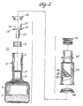
- Figure 1 is a side, partially sectional view, of one embodiment of the invention; and
- Figure 2 is an exploded view, partially in section, of the second embodiment of the invention.
- The mixing device shown in FIG. 1 generally comprises a
first container 10, astopper 16, a spike andplunger member 20, and asecond container 30. - The
first container 10 includes areservoir section 8, in which maybe contained aliquid component 6 intended, for example, for use as a diluent, and aneck section 12. The neck section may advantageously include aportion 14 of reduced cross-sectional area in which thestopper 16 can be disposed. - The spike and
plunger member 20 comprises amidportion 28, aplunger 22 extending from the midportion in the direction toward the reservoir, and aspike 24 extending from the midportion in the opposite direction. Themidportion 28 also includes a hole oraperture 26 therewithin. - The
second container 30 includes acentral portion 36, tiltable fluid-tight sealing means 32, an andimperforate cap 34, at opposite ends ofcentral body portion 36. The second container may contain a dry orpowder contents 38 intended to be mixed withdiluent 6. Anexternal safety housing 40 may be provided to guard against accidental application of force to thesecond container 30 which would cause premature mixing of thecontents 38 in the second container with thecontents 6 in the first container. Thesafety housing 40 is constructed so as to have a cross-sectional area larger than the cross-sectional area of theneck section 12 of thefirst container 10, and to be of such a length as to be extendible beyond the imperforate cap end of the second container. Thesafety housing 40 may be restrained in any suitable manner against movement into contact with the second container, such as by resting snugly against thefirst container 10 in the embodiment shown in FIG. 1. - The mixing device containing the contents within the first and second containers may be stored indefinitely until ready for mixing and use. When it is desired to effect mixing of the contents which, as previously indicated, may be any suitable medicaments which may be in a dry or lyophilized form, as indicated as 38 in the second container, and liquid diluent a such as indicated as 6 in the first container,
external safety housing 40 is first removed. After removal of the housing, pressure may be applied to theimperforate cap end 34 of the second container while restraining the first container so as to cause the second container to slide within the neck section of the first container and make contact with the spike andplunger member 20. Continued pressure will cause the plunger to dislodgestopper 16 and push it into the reservoir while at the same time cause thespike 24 to tilt thetiltable sealing member 32 out of fluid-tight sealing engagement thereby providing a continuous pathway for thecontents 38 of the second container to flow through thehole 26 in the midportion of the spike and plunger member into thereservoir 8 of the first container and thereby into contact with thecontents 6 therein. - Mixing of the contents may be effected by agitating the device and the mixed contents can be withdrawn as necessary from the mixing device through the
cap member 34 which may be adapted to receive a cannula or and I.V. connection. - An alternative embodiment of the invention is shown in FIG. 2 in which the mixing device is provided as a "kit" comprising
components - As can be seen, one component of the kit comprises the
first container 10 which includes areservoir 8 and aneck section 12. Also included is astopper 16 which is disposed within the neck section as shown in FIG. 1, and a spike andplunger member 20 disposed within the neck section adjacent the stopper, also as shown in FIG. 1. In this embodiment, however, acap member 42 is provided to seal the open end of the neck section so that the first container constitutes an individual unit. - The second container is provided as a second
separate unit 60 and comprises acentral body portion 36 with tiltable fluid-sealing means 32 at one end, animperforate cap 34 at the other end. However, in this embodiment, anexternal housing 44 is provided which extends from the imperforate cap end to beyond the tiltable sealing means 32. The extension beyond the seating means 32 is desirable to minimize or preclude contact therewith, thus preserving the sterile nature of the unit. In this arrangement, cap means 46 are also provided to seal the open end of theexternal housing 44 to also assist in maintaining the sterile condition. With the construction described in FIG. 2, the two components which form the kit may be stored indefinitely until it is desire to effect mixing of thecontents - When it is desired to use the kit, the
caps housing 44 is positioned around theneck portion 12 of the first container causing the second container to snugly but slidably fit within the neck portion with the tiltable sealing means 32 disposed adjacent thespike 24 of the spike andplunger member 20 located within the neck section of the first container. To effect mixing, pressure is applied to theimperforate cap end 34 of the second container until theplunger 22 dislodges the stopper 16 (into the reservoir 8) and thespike 24 tilts the tiltable sealing means 32 out of fluid-tight seal so as to permit thecontents 36 of the second container to flow through the neck section via thehole 26 in themidportion 28 of the spike and plunger means. - A
stop 18 shown in both FIG. 1 and FIG. 2 is provided to resist the further movement of the spike and plunger means toward the reservoir upon application of pressure to theimperforate cap end 34 of the second container, and to also permit sufficient resistance to enable thespike 24 to tilt the tiltable sealing means 32. - The invention has been described in accordance with the presently preferred embodiments. However, it is expressly understood that various changes and modifications may be made without departing from the scope of the invention, wherein:
Claims (5)
- A device suitable for mixing medicaments comprising:
a first container having a reservoir section and a neck section with a cross section less than the cross section of the reservoir;
a stopper snugly fit within the neck section adjacent the reservoir;
a spike and plunger member snugly fit within the neck section disposed adjacent the stopper on the side opposite the reservoir;
said spike and plunger member having a midportion with a hole therein, a plunger projecting from the midportion extending in the direction of the stopper and a spike extending from the midportion in the direction opposite the plunger;
a second container adapted to snugly fit within the neck section and deposed adjacent the spike;
said second container having a central body tiltable sealing means at one end thereof disposed adjacent the spike and an imperforate cap at the end of the central body opposite the tiltable sealing means; and
a first container, stopper, spike and plunger member and second container being arranged so that upon pressure applied to the second container while the first container is restrained, the plunger dislodges the stopper and the spike tilts the sealing means of the second container to provide a communicating path between the second container and the reservoir in the first container via the hole in the midportion of the spike and plunger member. - A device according to Claim 1, further comprising stop means in the neck section between the stopper and the midportion of the spike and plunger member to limit movement thereof in the direction of the reservoir.
- A device according to Claim 1 or 2, wherein said imperforate cap of the second container is adapted to receive means to extract contents of said device after being mixed therein.
- A device according to Claim 1,2 or 3, further comprising a removable external safety housing encompassing the second container and neck portion of the first container which extends beyond and spaced from the sealing means of the second container and removably restrained at the opposite end, said housing thereby substantially preventing accidental contact with the imperforate cap end of the second container.
- A kit suitable for mixing medicaments comprising:
a first container having a reservoir section and a neck section with a cross section less than the cross section of the reservoir;
a stopper snugly fit within the neck section adjacent the reservoir;
a spike and plunger member snugly fit within the neck section disposed adjacent the stopper on the side opposite the reservoir;
said spike and plunger member having a midportion with a hole therein, a plunger projecting from the midportion extending in the direction of the stopper and a spike extending from the midportion in the direction opposite the plunger;
a second container having a central body, a tiltable sealing means at one end thereof and an imperforate cap at the opposite end thereof;
a housing extending from the cap end around the central body means, but spaced therefrom, to beyond the sealing means;
a removable housing closure cap at the end of the housing extending beyond the sealing means;
the cross section of the central body of the second container, the housing thereof and the neck section of the first container being such that upon removal of the housing closure cap and placement of the second container within the neck section with the tiltable sealing means disposed adjacent the spike of the spike and plunger member, the housing surrounds the neck portion and a portion of the central body of the second container snugly fits into the neck section;
the first container, stopper, spike member and second container being arranged so that upon pressure applied to the second container while the first container is restrained, the plunger of the spike member dislodges the stopper and the spike of the spike member tilts the sealing means of the second container, to provide a communication path between the second container and the reservoir in the first container via the hole in the midportion of the spike and plunger member, thereby enabling the contents of the first and second containers to make contact in the reservoir where they mix.
Applications Claiming Priority (2)
| Application Number | Priority Date | Filing Date | Title |
|---|---|---|---|
| US07/446,396 US4979941A (en) | 1989-12-05 | 1989-12-05 | Device suitable for mixing medication |
| US446396 | 1989-12-05 |
Publications (1)
| Publication Number | Publication Date |
|---|---|
| EP0431779A1 true EP0431779A1 (en) | 1991-06-12 |
Family
ID=23772432
Family Applications (1)
| Application Number | Title | Priority Date | Filing Date |
|---|---|---|---|
| EP19900312513 Withdrawn EP0431779A1 (en) | 1989-12-05 | 1990-11-16 | Device suitable for mixing medication |
Country Status (4)
| Country | Link |
|---|---|
| US (1) | US4979941A (en) |
| EP (1) | EP0431779A1 (en) |
| AU (1) | AU6692690A (en) |
| CA (1) | CA2030135A1 (en) |
Cited By (3)
| Publication number | Priority date | Publication date | Assignee | Title |
|---|---|---|---|---|
| EP0528231A1 (en) * | 1991-08-08 | 1993-02-24 | Nissho Corporation | Drug vessel |
| US5342346A (en) * | 1992-04-10 | 1994-08-30 | Nissho Corporation | Fluid container |
| US5348550A (en) * | 1991-11-15 | 1994-09-20 | Nissho Corporation | Drug vessel |
Families Citing this family (34)
| Publication number | Priority date | Publication date | Assignee | Title |
|---|---|---|---|---|
| US5195966A (en) * | 1987-12-24 | 1993-03-23 | Diversey Limited | Treatment of mastitis and applicator therefor |
| NZ334983A (en) | 1991-12-18 | 2001-03-30 | Icu Medical Inc | Medical valve with a resilient seal |
| US5484406A (en) * | 1992-11-19 | 1996-01-16 | Baxter International Inc. | In-line drug delivery device for use with a standard IV administration set and a method for delivery |
| US5665066A (en) * | 1993-09-03 | 1997-09-09 | Ultradent Products, Inc. | Methods and apparatus for mixing and dispensing multi-part compositions |
| US5328462A (en) * | 1993-09-03 | 1994-07-12 | Ultradent Products, Inc. | Methods and apparatus for mixing and dispensing multi-part compositions |
| US5522804A (en) * | 1994-02-15 | 1996-06-04 | Lynn; Lawrence A. | Aspiration, mixing, and injection syringe |
| US5695777A (en) * | 1994-05-10 | 1997-12-09 | Medtronic, Inc. | Absorptive wound dressing for wound healing promotion |
| JPH10504736A (en) | 1994-06-24 | 1998-05-12 | アイシーユー メディカル、インコーポレイティッド | Fluid transfer device and method of use |
| US5738663A (en) | 1995-12-15 | 1998-04-14 | Icu Medical, Inc. | Medical valve with fluid escape space |
| DE19615422A1 (en) | 1996-04-19 | 1997-11-20 | Boehringer Ingelheim Kg | Two-chamber cartridge for propellant-free MDIs |
| CA2314900C (en) * | 1997-12-19 | 2009-02-24 | United States Surgical Corporation | Fibrin mixture and dispenser assembly |
| US5927549A (en) * | 1998-03-20 | 1999-07-27 | Aptargroup, Inc. | Dispensing structure with frangible membrane for separating two products |
| DE19847968A1 (en) | 1998-10-17 | 2000-04-20 | Boehringer Ingelheim Pharma | Separate storage of an active material and a solvent comprises a closure cap and a container, with a chamber attached to the unit. |
| DE60227245D1 (en) * | 2001-03-13 | 2008-08-07 | Mdc Invest Holdings Inc | PRE-FILLED SAFETY DILUENT INJECTOR |
| KR100569223B1 (en) * | 2005-06-28 | 2006-04-10 | 오기범 | Integrated infusion container |
| AU2008236931A1 (en) * | 2007-04-05 | 2008-10-16 | Fredrick Michael Coory | A dispenser |
| US8070014B2 (en) | 2007-08-24 | 2011-12-06 | Seaquist Closures L.L.C. | Liner piercing twist closure |
| EP2077132A1 (en) | 2008-01-02 | 2009-07-08 | Boehringer Ingelheim Pharma GmbH & Co. KG | Dispensing device, storage device and method for dispensing a formulation |
| US10011906B2 (en) | 2009-03-31 | 2018-07-03 | Beohringer Ingelheim International Gmbh | Method for coating a surface of a component |
| EP3508239B1 (en) | 2009-05-18 | 2020-12-23 | Boehringer Ingelheim International GmbH | Adapter, inhalant apparatus and atomizer |
| UA107097C2 (en) | 2009-11-25 | 2014-11-25 | Бьорінгер Інгельхайм Інтернаціональ Гмбх | Dispenser |
| WO2011064163A1 (en) | 2009-11-25 | 2011-06-03 | Boehringer Ingelheim International Gmbh | Nebulizer |
| US10016568B2 (en) | 2009-11-25 | 2018-07-10 | Boehringer Ingelheim International Gmbh | Nebulizer |
| EP2585151B1 (en) | 2010-06-24 | 2018-04-04 | Boehringer Ingelheim International GmbH | Nebulizer |
| US8523814B2 (en) | 2010-09-28 | 2013-09-03 | Covidien Lp | Self-venting cannula assembly |
| WO2012130757A1 (en) | 2011-04-01 | 2012-10-04 | Boehringer Ingelheim International Gmbh | Medical device comprising a container |
| US9827384B2 (en) | 2011-05-23 | 2017-11-28 | Boehringer Ingelheim International Gmbh | Nebulizer |
| WO2013152894A1 (en) | 2012-04-13 | 2013-10-17 | Boehringer Ingelheim International Gmbh | Atomiser with coding means |
| ES2836977T3 (en) | 2013-08-09 | 2021-06-28 | Boehringer Ingelheim Int | Nebulizer |
| WO2015018904A1 (en) | 2013-08-09 | 2015-02-12 | Boehringer Ingelheim International Gmbh | Nebulizer |
| US10195374B2 (en) | 2014-05-07 | 2019-02-05 | Boehringer Ingelheim International Gmbh | Container, nebulizer and use |
| WO2015169430A1 (en) | 2014-05-07 | 2015-11-12 | Boehringer Ingelheim International Gmbh | Nebulizer |
| KR102492824B1 (en) | 2014-05-07 | 2023-01-30 | 베링거 인겔하임 인터내셔날 게엠베하 | Nebulizer, indicator device and container |
| US9522771B2 (en) * | 2015-04-30 | 2016-12-20 | Fang Lin Yang | Container for receiving two materials |
Citations (4)
| Publication number | Priority date | Publication date | Assignee | Title |
|---|---|---|---|---|
| US3490437A (en) * | 1966-10-17 | 1970-01-20 | Thomas T Bakondy | Embryonic organ cells in a state of preservation and methods for preserving the same |
| US3563415A (en) * | 1969-06-04 | 1971-02-16 | Multi Drop Adapter Corp | Multidrop adapter |
| US3857392A (en) * | 1969-06-04 | 1974-12-31 | Ims Ltd | Intravenous container with dislodgeable septum and dislodging piercer |
| US3882909A (en) * | 1973-07-05 | 1975-05-13 | Ims Ltd | Trans-a-jet 1 |
Family Cites Families (10)
| Publication number | Priority date | Publication date | Assignee | Title |
|---|---|---|---|---|
| US3603484A (en) * | 1969-02-28 | 1971-09-07 | Mix O Matic Corp | A two-compartment mixing and dispensing device |
| US3858580A (en) * | 1969-06-04 | 1975-01-07 | Ims Ltd | Intravenous container mixing assembly |
| US3674028A (en) * | 1969-06-04 | 1972-07-04 | Ims Ltd | Multi-mix |
| US3670728A (en) * | 1970-06-01 | 1972-06-20 | Cutter Lab | Apparatus for intravenous administration of a fluid from a dual-chamber flask having an internal upset-table septum normally separating two axially-in-line chambers and having a pierceable end stopper |
| US3802604A (en) * | 1972-02-28 | 1974-04-09 | Oreal | Device for storing two products separately and dispensing them simultaneously |
| US3941171A (en) * | 1973-07-05 | 1976-03-02 | Ims Limited | Fluid transfer device |
| US4392850A (en) * | 1981-11-23 | 1983-07-12 | Abbott Laboratories | In-line transfer unit |
| FR2538706B1 (en) * | 1982-12-29 | 1986-03-14 | Merck Sharp & Dohme | SOLUTE PREPARATION AND DELIVERY ASSEMBLY |
| US4610374A (en) * | 1984-10-29 | 1986-09-09 | Dougherty Brothers Company | Apparatus for mixing flowable materials in sealed containers |
| US4871354A (en) * | 1986-07-24 | 1989-10-03 | The West Company | Wet-dry bag with lyphozation vial |
-
1989
- 1989-12-05 US US07/446,396 patent/US4979941A/en not_active Expired - Fee Related
-
1990
- 1990-11-16 EP EP19900312513 patent/EP0431779A1/en not_active Withdrawn
- 1990-11-16 CA CA 2030135 patent/CA2030135A1/en not_active Abandoned
- 1990-11-23 AU AU66926/90A patent/AU6692690A/en not_active Abandoned
Patent Citations (4)
| Publication number | Priority date | Publication date | Assignee | Title |
|---|---|---|---|---|
| US3490437A (en) * | 1966-10-17 | 1970-01-20 | Thomas T Bakondy | Embryonic organ cells in a state of preservation and methods for preserving the same |
| US3563415A (en) * | 1969-06-04 | 1971-02-16 | Multi Drop Adapter Corp | Multidrop adapter |
| US3857392A (en) * | 1969-06-04 | 1974-12-31 | Ims Ltd | Intravenous container with dislodgeable septum and dislodging piercer |
| US3882909A (en) * | 1973-07-05 | 1975-05-13 | Ims Ltd | Trans-a-jet 1 |
Cited By (4)
| Publication number | Priority date | Publication date | Assignee | Title |
|---|---|---|---|---|
| EP0528231A1 (en) * | 1991-08-08 | 1993-02-24 | Nissho Corporation | Drug vessel |
| US5348060A (en) * | 1991-08-08 | 1994-09-20 | Nissho Corporation | Drug vessel |
| US5348550A (en) * | 1991-11-15 | 1994-09-20 | Nissho Corporation | Drug vessel |
| US5342346A (en) * | 1992-04-10 | 1994-08-30 | Nissho Corporation | Fluid container |
Also Published As
| Publication number | Publication date |
|---|---|
| US4979941A (en) | 1990-12-25 |
| AU6692690A (en) | 1991-06-13 |
| CA2030135A1 (en) | 1991-06-06 |
Similar Documents
| Publication | Publication Date | Title |
|---|---|---|
| US4979941A (en) | Device suitable for mixing medication | |
| US4244467A (en) | Device for the extemporaneous preparation of a solution under sterile conditions | |
| US5358501A (en) | Storage bottle containing a constituent of a medicinal solution | |
| EP0897708B1 (en) | Drug delivery container having a luer filter | |
| US4722733A (en) | Drug handling apparatus and method | |
| US4346820A (en) | Apparatus for mixing and dispersing two substances under sterile conditions | |
| US4392850A (en) | In-line transfer unit | |
| US5895383A (en) | Medicament container closure with recessed integral spike access means | |
| US4392851A (en) | In-line transfer unit | |
| CA1071585A (en) | Mixing vial | |
| US4994056A (en) | Unit dose medicament storing and mixing system | |
| US5445631A (en) | Fluid delivery system | |
| US5100010A (en) | Containment seal assembly | |
| US5766149A (en) | Mixing and delivery system | |
| US5330048A (en) | Controlled access mixing vial | |
| EP0357288A1 (en) | Device for storage, mixing and dispensing of two different fluids | |
| JPH0669475B2 (en) | Double chamber bottle | |
| JPH05146483A (en) | Medicine container and distribution system | |
| US20080065027A1 (en) | Disposable Safety Syringe to Prevent Needlestick Injuries and Reuse | |
| KR19980024227A (en) | Resealable multiple position glass bottle connection assembly for effective delivery of liquids | |
| US4591357A (en) | Container for drug isolation, storage and subsequent mixing | |
| JPS62281947A (en) | Mixing and distribution apparatus | |
| JPH04231051A (en) | Suction/transfer assembly for medicine liquid | |
| JPH0683719B2 (en) | An elongated container having two separated compartments, one of which is an extension of the other | |
| US3630199A (en) | Unitized injection system |
Legal Events
| Date | Code | Title | Description |
|---|---|---|---|
| PUAI | Public reference made under article 153(3) epc to a published international application that has entered the european phase |
Free format text: ORIGINAL CODE: 0009012 |
|
| AK | Designated contracting states |
Kind code of ref document: A1 Designated state(s): AT BE CH DE DK ES FR GB GR IT LI LU NL SE |
|
| STAA | Information on the status of an ep patent application or granted ep patent |
Free format text: STATUS: THE APPLICATION IS DEEMED TO BE WITHDRAWN |
|
| 18D | Application deemed to be withdrawn |
Effective date: 19911213 |