EP0430890B1 - Wall element for dry construction of walls, building system for securing slopes and slope wall built with the building system - Google Patents
Wall element for dry construction of walls, building system for securing slopes and slope wall built with the building system Download PDFInfo
- Publication number
- EP0430890B1 EP0430890B1 EP90810915A EP90810915A EP0430890B1 EP 0430890 B1 EP0430890 B1 EP 0430890B1 EP 90810915 A EP90810915 A EP 90810915A EP 90810915 A EP90810915 A EP 90810915A EP 0430890 B1 EP0430890 B1 EP 0430890B1
- Authority
- EP
- European Patent Office
- Prior art keywords
- wall
- side walls
- shield
- walls
- trough
- Prior art date
- Legal status (The legal status is an assumption and is not a legal conclusion. Google has not performed a legal analysis and makes no representation as to the accuracy of the status listed.)
- Expired - Lifetime
Links
Images


Classifications
-
- E—FIXED CONSTRUCTIONS
- E02—HYDRAULIC ENGINEERING; FOUNDATIONS; SOIL SHIFTING
- E02D—FOUNDATIONS; EXCAVATIONS; EMBANKMENTS; UNDERGROUND OR UNDERWATER STRUCTURES
- E02D29/00—Independent underground or underwater structures; Retaining walls
- E02D29/02—Retaining or protecting walls
- E02D29/025—Retaining or protecting walls made up of similar modular elements stacked without mortar
Abstract
Description
Die vorliegende Erfindung betrifft ein Mauerelement für die Trockenbauweise von Mauern gemäss dem Oberbegriff des Patentanspruchs 1, einen Bausatz zur Befestigung von Böschungen nach Patentanspruch 12 und eine Böschungsmauer nach Patentanspruch 14.The present invention relates to a wall element for the dry construction of walls according to the preamble of
Elemente dieser Art sind im Landschaftsgartenbau sowie zur Stützung von Steilböschungen im allgemeinen bekannt. Die wohl älteste Form eines aus Vorderwand, Bodenwand und zwei Seitenwänden gebildeten trogförmigen Elementes ist in der US-A- 1 542 909 beschrieben. Dieses Element ist als ein mit Mörtel füllbarer Mauerstein gedacht, dessen Trog in Richtung der Längenausdehnung der Mauer liegt.Elements of this type are generally known in landscaping and for supporting steep slopes. The probably oldest form of a trough-shaped element formed from front wall, bottom wall and two side walls is described in US-A-1 542 909. This element is intended as a brick that can be filled with mortar, the trough of which lies in the direction of the length of the wall.
Im CH-A- 587 390 ist ein ähnliches Element beschrieben, das aber zum Schichten vorgesehen ist und zu diesem Zweck an der Bodenunterseite zwei zum Schild senkrecht angeordnete nutenartige Vertiefungen aufweist, die bei versetzt geschichteten Elementen über die Seitenwände der darunterliegenden Elemente zu liegen kommen. Dadurch erhält eine solche Stützmauer eine ausserordentlich hohe Stabilität, weil sich die Elemente seitlich nicht verschieben können. Um auch eine Verschiebung nach vorn zumindest zu erschweren, ist der Schild höher als die Seitenwände ausgebildet, so dass auf Lücke angeordnete obere Elemente hinter die Schilde der beiden darunter befindlichen Elemente liegen, und damit durch das Gewicht eine Pressung nach unten erfahren. Die Tröge sind mit Erde bzw. Humus gefüllt und können bepflanzt werden. Dadurch kann einerseits die Betonmauer begrünt werden und anderseits verschafft das Wurzelwerk der Pflanzen eine Verbindung nach hinten zum gewachsenen Boden.A similar element is described in CH-A-587 390, but which is intended for layering and for this purpose has two groove-like depressions arranged on the bottom underside which are perpendicular to the shield and which, in the case of staggered layered elements, over the side walls of the elements below come to rest. This provides such a retaining wall with extremely high stability because the elements cannot move laterally. In order to at least make it difficult to move it forward, the shield is formed higher than the side walls, so that upper elements arranged on a gap lie behind the shields of the two elements located below, and are thus pressed downward by the weight. The troughs are filled with soil or humus and can be planted. This means that the concrete wall can be greened on the one hand and on the other hand the roots of the plants create a connection backwards to the grown soil.
Eine Variante dieses Elementes ist in der EP-A- 0 047 718 beschrieben. Sowohl der Schild als auch Flügel erstrecken sich beidseits über die Seitenwände hinaus. Eine Querwand im Trog teilt diesen in eine vordere geschlossene Schüssel und in einen hinteren, nach hinten offenen Trog. Im Verbund mit andern Elementen geben die verbreiterten Schilde und die abstehenden Flügel weitere Kammern, die zusammen mit den Schüsseln vorn Beruhigungsbecken bei Wasserläufen oder Seen im Bereich der Wasserspiegel bilden. Eine Bepflanzung der hinteren Tröge ist damit möglich, indem die Schüsseln ein Herausspülen der Erde aus den Trögen wenigstens erschweren.A variant of this element is described in EP-A-0 047 718. Both the shield and wing extend beyond the side walls on both sides. A transverse wall in the trough divides it into a front closed bowl and a rear trough that is open to the rear. In conjunction with other elements, the widened shields and the protruding wings give further chambers, which together with the bowls in front form calming basins near water courses or lakes in the area of the water level. A planting of the rear troughs is possible in that the bowls at least make it difficult to wash the soil out of the troughs.
Es hat sich nun gezeigt, dass die Elemente gemäss der vorgenannten CH-A- 587 390 bei grösserer Bauhöhe, d.h. über etwa 7 m, zusammenbrechen können, insbesondere, wenn der Trog mit einem kompressiblen Material, wie z.B. Humus, gefüllt ist. Untersuchungen an gebrochenen Elementen haben ergeben, dass die Unterstützung am Boden in den Vertiefungen ein Moment auf die Seitenwände bewirken, so dass die Seitenwand abgebrochen werden kann.It has now been shown that the elements according to the aforementioned CH-A-587 390 have a greater overall height, ie about 7 m, can collapse, especially if the trough is filled with a compressible material such as humus. Studies on broken elements have shown that the support on the floor in the recesses causes a moment on the side walls so that the side wall can be broken off.
Es ist nun eine Aufgabe, diese Nachteile bei sämtlichen Ausbildungsformen solcher Elemente zu beheben.It is now a task to remedy these disadvantages in all forms of training of such elements.
Erfindungsgemäss erfolgt dies durch die Merkmale im kennzeichnenden Teil des unabhängigen Patentanspruchs 1.According to the invention, this is done by the features in the characterizing part of
Ausführungsbeispiele werden nachfolgend anhand der Zeichnung erläutert. Es zeigen:
- Fig. 1
- eine perspektivische Ansicht eines Mauerelementes gemäss der CH-A- 587 390 in einer gemäss der Erfindung geänderten Form,
- Fig. 2
- eine perspektivische Ansicht einer zweiten Ausführungsform,
- Fig. 3
- eine Schnittansicht einer trocken gebauten Mauer mit Elementen gemäss Fig. 2, wobei die Schnittebene hinter den Schilden der Elemente liegt,
- Fig. 4
- eine perspektivische Ansicht einer dritten Ausführungsform,
- Fig. 5 und 6
- perspektivische Ansichten eines Elementes nach Fig. 1 oder 2 für Verwendung zur Verbauung von Uferböschungen im Bereich des Wasserspiegels,
- Fig. 7
- eine perspektivische Ansicht einer vierten Ausführungsform,
- Fig. 8
- eine perspektivische Ansicht einer fünften Ausführungsform,
- Fig. 9
- eine perspektivische Ansicht von zwei Elementen nach Fig. 8 nebeneinander mit einem geotextilen Gewebe zur Verankerung der Mauerelemente,
- Fig. 10
- eine perspektivische Ansicht eines Mauerelementes mit einem Schild in abgewandelter Form,
- Fig. 11
- eine perspektivische Darstellung eines Böschungssteines einer sechsten Ausführungsform,
- Fig. 12
- eine perspektivische Darstellung eines Böschungssteines einer siebten Ausführungsform,
- Fig. 13
- einen Grundriss einer Böschungsmauer mit Böschungssteinen der Ausführungsform nach Fig. 12,
- Fig. 14
- einen Aufriss einer Böschungsmauer nach Fig. 13,
- Fig. 15
- einen Grundriss einer Böschungsmauer mit Böschungssteinen der Ausführungsform nach Fig. 11, und
- Fig. 16
- einen Aufriss einer Böschungsmauer mit Böschungssteinen aus sechster und siebter Ausführungsform kombiniert.
- Fig. 1
- 2 shows a perspective view of a wall element according to CH-A-587 390 in a form modified according to the invention,
- Fig. 2
- 2 shows a perspective view of a second embodiment,
- Fig. 3
- 3 shows a sectional view of a dry-built wall with elements according to FIG. 2, the sectional plane being behind the shields of the elements,
- Fig. 4
- 2 shows a perspective view of a third embodiment,
- 5 and 6
- perspective views of an element according to FIG. 1 or 2 for use in the construction of bank embankments in the area of the water level,
- Fig. 7
- 2 shows a perspective view of a fourth embodiment,
- Fig. 8
- 2 shows a perspective view of a fifth embodiment,
- Fig. 9
- 8 shows a perspective view of two elements according to FIG. 8 side by side with a geotextile fabric for anchoring the wall elements,
- Fig. 10
- a perspective view of a wall element with a shield in a modified form,
- Fig. 11
- 1 shows a perspective representation of a slope stone of a sixth embodiment,
- Fig. 12
- 1 shows a perspective illustration of a slope stone of a seventh embodiment,
- Fig. 13
- 12 shows a plan view of a slope wall with slope stones of the embodiment according to FIG. 12,
- Fig. 14
- 13 shows an elevation of a slope wall according to FIG. 13,
- Fig. 15
- 11 shows a plan view of a slope wall with slope stones of the embodiment according to FIG. 11, and
- Fig. 16
- an elevation of a slope wall combined with slope stones from sixth and seventh embodiment.
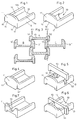
Der Mauerstein nach Fig. 1 zeigt die grundsätzlich bekannte Form mit Bodenwand 10, einem senkrecht darauf stehenden Schild 11 und beidseits der Bodenwand 10 angeordneten Seitenwänden 12, 13. Wie unten am Schild 11 gut erkennbar ist, weist die Bodenwand 10 auf ihrer Unterseite zwei parallele rinnenförmige Vertiefungen 14, 15 auf. Der Schild ist oben und seitlich gerundet und ebenso können auch sämtliche Stirnflächen gerundet sein, um so einem natürlichen Stein zu gleichen. Der Schild 11 kann entweder gemäss der CH-A- 587 390 seitlich mit den Seitenwänden fluchten oder gemäss der EP-A- 0 047 718 die Seitenwände überragen.1 shows the fundamentally known shape with
Wie Fig. 3 zeigt, sind die Seitenwände 12′,13′ und 12′′, 13′′ dicker dimensioniert als beim bekannten Böschungsstein nach der CH-A- 587 390 sind, und zwar ist die obere Stirnfläche 12a, 13a (Fig. 1) abgeflacht und befindet sich senkrecht über der rinnenförmigen Vertiefung 14, 15, derart, dass bei im Verbund geschichteten Elementen die Bodenwand 10 eines Elementes A unterhalb seiner Seitenwände 12, 13 mit Seitenwänden 13′ bzw. 12′′ von darunter befindlichen Elementen B bzw. C unterstützt ist. Wie die beiden vertikalen strichpunktierten Linien S1, S2 deutlich zeigen, drücken die Kräfte gemäss den Pfeilen P1, P2 immer auf Seitenwände 13′, 12˝, so dass keine Momente auf die Auflagestellen wirken können, die das Element zerstören könnten.As shown in Fig. 3, the side walls 12 ', 13' and 12 '', 13 '' are dimensioned thicker than in the known embankment stone according to CH-A- 587 390, namely the
Wie Fig. 1 und 3 zeigen, könnte anstelle der rillenartigen Vertiefungen 14, 15 die Bodenunterseite mit zwei seitlichen Halteleisten 16, 17 ausgebildet sein, die bis in den Schild 11 hinein ragen. Der Schild 11 seinerseits könnte aber auch nach unten verlängert sein, so dass die breite Vertiefung 18 zwischen den Halteleisten 16, 17 von vorn unsichtbar bleibt.1 and 3 show, instead of the groove-
Der seitlich jedoch zumindest oben vorstehende Schild 11 gestattet, dass im Verbund geschichtete Elemente nach Fig. 1 oder 2 mit Partien vor den Seitenwänden 12, 13 an der Hinterseite der Schilde 11 anstehen und damit einen Halt gegen ein Abgleiten nach vorn erhalten. Dadurch erfährt die geschichtete Mauer einen Neigungswinkel, der durch die Dicke des Schildes 11 bestimmt ist. Oftmals ist es jedoch erwünscht, eine senkrecht erscheinende Mauer zu bilden. Dies kann bei Mauerelementen der vorbeschriebenen Art nach Fig. 2 oder 3 dadurch erhalten werden, dass gemäss Fig. 4 der Schild 11 beidseits an den unteren seitlichen Partien Ausnehmungen 41, 42 hat, deren Begrenzungslinien die gleiche Form haben, wie der Schild 11 an den seitlichen oberen Partien. Damit können die Elemente derart senkrecht neben- und übereinander geschichtet werden, dass die Elemente mit ihren angrenzenden Schilden in diese Ausnehmungen 41, 42 eingreifen, so dass keine Versetzung um die Dicke der Schilde notwendig ist und die Mauer senkrecht aufgebaut werden kann. Damit entfällt die Sicherheit mit dem Halt hinter den Schilden und die Steine halten nur aufgrund der Reibung, was allerdings in vielen Fällen genügt.The
Anstelle der aufwendigen Fabrikationsform für Elemente gemäss der vorgenannten EP-A- 0 047 718, die im Trog zwei Kammern haben, kann dank der verdickten Seitenwände 12, 13 gemäss Fig. 5 je eine schlitzartige Ausnehmung 51, 52 in den beiden Seitenwänden 12, 13 in gleichem Abstand hinter dem Schild 11 angeordnet sein. Mit einer plattenförmigen Trennwand 53 kann gemäss Fig. 6 ebenfalls ein Element für Verbauung von Uferpartien geschaffen werden, das mit einer vorderen Beruhigungskammer 54 und einem nach hinten offenen Trog 55 versehen ist.Instead of the elaborate fabrication form for elements according to the aforementioned EP-A-0 047 718, which have two chambers in the trough, thanks to the thickened
Im besonderen können durch die erfindungsgemässe Ausbildung der Seitenwände 12, 13 die Elemente für sämtliche Anwendungen mit solchen schlitzartigen Ausnehmungen 51, 52 versehen sein, denn durch die besonders günstige Anordnung der Auflagen, wie sie in Fig. 3 dargestellt sind, erfolgt an keiner Stelle eine mögliche zerstörende Krafteinwirkung, wie sie bei den frühe- ren Ausbildungsformen möglich waren.In particular, due to the inventive design of the
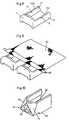
Anstelle der schlitzartigen Ausnehmungen 51, 52 könnten die oberen Stirnflächen 12a, 13a der Seitenwände 12, 13 mit Einkerbungen 71, 72 in gleichem Abstand hinter dem Schild 11 versehen sein (Fig. 8). In diese Einkerbungen könnte gemäss Fig. 9 ein Betoneisen 81 oder dgl. eingelegt sein, um das ein geotextiles Gewebe 82 gefaltet ist und das mit seinem freien Ende bis in das weit hinten liegende Erdreich eingelegt sein kann, um der Mauer eine grosse Stabilität zu verleihen.Instead of the slot-
Schliesslich wird gemäss Fig. 10 noch eine Variante zum gerundeten Schild 11 der vorerwähnten Ausführungsbeispiele angegeben. Dieser Schild 91 besteht aus drei Dreiecksflächen 92, 93, 94, von denen die vordere Fläche 92 senkrecht zur Bodenwand 95 angeordnet ist und ein gleichschenkliges oder gleichseitiges Dreieck darstellt. Die beiden weiteren Dreiecksflächen 93, 94 sind ebenfalls gleichschenklige oder gleichseitige Dreiecke, deren Basislinien im Gegensatz zum erstgenannten Dreieck 92 nun oben liegen und die obere Begrenzung bilden.Finally, according to FIG. 10, a variant of the rounded
Wie übrigens Fig. 2 zeigt, kann die Bodenwand 10 hinten eine Ausnehmung 20 haben. Diese könnte aber auch mittig angeordnet sein, so dass der hintere Rand mit einem Quersteg abgeschlossen erscheint. Mit einer solchen Ausnehmung kann insbesondere das grössere Gewicht der Elemente infolge der dickeren Seitenwände wieder verringert werden.2 shows, the
Oftmals muss Oberflächenwasser bei Regen oder in feuchtem Gelände gesammelt und abgeführt werden. Mit einer Einbuchtung 73 mittig im Schild 11 (Fig. 7) lassen sich diese Mauerelemente zu einem Kanal zusammenstellen, der beispielsweise bei geneigter Ausbildung der Elementen-Wand eine Rinne über die gesamte Höhe der Mauer bildet.Surface water often has to be collected and drained off when it rains or in damp terrain. With an
Die beiden Böschungssteine nach Fig. 11 und 12 haben je eine Bodenwand 104, 124, die ebenfalls zum Teil ausgenommen sein kann, zwei Seitenwände 101, 102, 121, 122 sowie einen Schild 103, 123. Die Seitenwände 101, 102 in Fig. 11 haben am schildseitigen Ende einen grösseren Abstand als am freien Ende und die Seitenwände 121, 122 in Fig. 12 haben demgegenüber am schildseitigen Ende einen kleineren Abstand als am freien Ende. Damit unterscheiden sich die beiden Böschungssteine nach Fig. 11 und 12 lediglich darin, dass bei gleich gebauten Trögen 104, 124 mit sich keilförmig verbreiterndem Abstand der Seitenwände 101, 102 bzw. 121, 122 lediglich der Schild 103, 123 jeweils am einen der beiden Enden angeordnet sein könnte. Die Schilde 103, 123 sind nach oben konvex gewölbt und die Stirnkanten können gerundet sein.11 and 12 each have a
Durch diese Anordnung wird jeweils ein oben und hinten offener Trog gebildet. Der Schild 103, 123 übersteht die jeweiligen Seitenwände 101, 102 und 121, 122 wenigstens nach oben, aber sie könnten diese auch seitlich überstehen. Dadurch ergibt sich beim Bau einer Mauer ein Halt für den jeweils oberen Stein und dieser kann damit nicht nach vorn abgleiten. Im hinteren Bereich der Bodenwand 104,124 kann eine nach oben ragende Querrippe vorgesehen sein, um damit eine schalenförmige Vertiefung über der Bodenwand zu bilden. Solche Querrippen sind in den Fig. 11 und 12 nicht dargestellt, da sich jedermann eine solche Erhöhung vorstellen kann.With this arrangement, a trough open at the top and rear is formed. The
Der Zweck der damit gebildeten Vertiefung liegt darin, dass Wasser gespeichert werden kann, damit das Erdreich nicht austrocknet, auch wenn der Schild einer starken Besonnung ausgesetzt sein sollte. Damit haben die Pflanzen für die Begrünung der Mauer Feuchtigkeit bis sie mit ihren Wurzeln in das hinter der Mauer befindliche Erdreich hineinwachsen können.The purpose of the deepening thus formed is that water can be stored so that the soil does not dry out, even if the shield is exposed to strong sunshine. This means that the plants have moisture for the greening of the wall until their roots can grow into the soil behind the wall.
Wenn sich beim Stein nach Fig. 11 der Trog nach hinten verkleinert, so gibt dies mittels des Wurzelballens einen zusätzlichen Halt. Die genannte Rippe kann beim Stein nach Fig. 12 einen ähnlichen Zweck erfüllen, indem im Verbund einer Mauer auf diese Weise am hinteren Teil des Steins auch eine Verengung gebildet wird.If the trough in the stone according to FIG. 11 shrinks to the rear, this gives an additional hold by means of the root ball. The mentioned rib can serve a similar purpose in the stone according to FIG. 12, in that a constriction is also formed on the rear part of the stone in the bond of a wall.
An den oberen Stirnflächen 105, 106, 125, 126 der Seitenwände 101, 102, 121, 122 sind sich gegenüberliegende Ausnehmungen 107, 108, 127, 128 angeordnet. In diese Ausnehmungen können beim Bau von Mauern Betoneisen oder Balken aus Beton eingelegt werden, um die Steine seitlich zu verbinden oder zur Halterung von Geotextilien gemäss Fig. 9. Andererseits kann auch der Schild 103, wenn er unten einen unter den Boden 104 vorstehenden Lappen 109 hat in diese Ausnehmungen eingreifen und so eine Verzahnung bilden.
Wie in Fig. 11 angedeutet, kann die Bodenwand 104 in ihrer unteren Fläche zwei Vertiefungen 130, 131 aufweisen. Diese Vertiefungen 130, 131 können parallel zu den Seitenwänden 101, 102 angeordnet sein, sie können aber auch einen anderen Winkel zur Schildvorderfläche bilden, nämlich so, dass beim Schichten von Steinen die Seitenwände 101, 102 in die Vertiefungen 130, 131 eingreifen und damit eine seitliche Verzahnung bilden. Die Nuten können auch gekreuzt oder paarweise V-förmig angeordnet sein, um sowohl bei Verwendung gleicher Steine in Anordnung nach Fig. 15 oder ungleicher Steine in Anordnung nach Fig. 16 ein Eingreifen zu ermöglichen.As indicated in FIG. 11, the
Fig. 13 und 14 zeigen je eine Mauer, aufgebaut mit Böschungssteinen nach Fig. 12. Mit derartigen Steinen lassen sich sowohl gerade Mauern als auch konkav gewölbte Mauern bilden.FIGS. 13 and 14 each show a wall, built with embankment stones according to FIG. 12. With such stones, both straight walls and concavely curved walls can be formed.
Anders mit den Böschungssteinen nach Fig. 11, mit denen sich zwar auch gerade Mauern gemäss Fig. 15 bilden lassen, jedoch können vorteilhafterweise Mauern mit konvexer Wölbung hergstellt werden.The situation is different with the embankment stones according to FIG. 11, with which straight walls according to FIG. 15 can also be formed, but walls with a convex curvature can advantageously be produced.
Die Vorderansicht nach Fig. 16 zeigt nun eine Mauer wie sie vorteilhaft unter Verwendung beider Böschungssteinarten nach Fig. 11 und Fig. 12 gebaut werden kann. Obwohl sich hier immer noch eine Betonung der horizontalen Linien ergibt, ist wenigstens die Regelmässigkeit in vertikaler Hinsicht nicht mehr gegeben. Damit erhält die Mauer eine Sichtfläche, die eher an eine Natursteinmauer erinnert als beispielsweise Mauern nach Fig. 13 - 15.The front view according to FIG. 16 now shows a wall as it can advantageously be built using both types of embankment stones according to FIGS. 11 and 12. Although the horizontal lines are still emphasized here, at least the regularity in vertical terms is no longer given. This gives the wall a visible surface that is more reminiscent of a natural stone wall than, for example, walls according to FIGS. 13-15.
Selbstverständlich könnten auch Schattenfugen im Schild 103, 123 zu einer starken Veränderung des Bildes führen. Obwohl in der Zeichnung Fig. 11, 12 Schilde 103, 123 mit flachen Frontwänden dargestellt sind, können sie selbstverständlich auch gewölbt sein, wie Fig. 13 bis 16 zeigen, wo die Schilde gewölbt dargestellt sind und stufenlos in die Seitenwände übergehen.Of course, shadow gaps in
Claims (14)
- A concrete wall element for the dry construction of walls, with a front shield (11,91) two side walls (12,13) extending to the rear and a lower ground wall (10,95), such that the wall element is trough-shaped, wherein the ground wall (10,95) on its underside includes at least one recess (14,15,18) arranged parallel to the side walls (12,13,11,91), and wherein each side wall (12,13) is narrower on its free upper front surface (12a,13a) than at its base part, wherein at least one border area of the underside of the ground wall has one recess (14,15,18) arranged in the area beneath one of the side walls (12,13), and wherein the side walls in the area of the ground surface form respective rib-shaped ledges (16,17) located on the outside and extending over at least part of the length of the trough, characterized in that the thickness of the side walls (12,13) at their base part is greater than the width of said rib-shaped ledges (16,17), providing that when the wall elements are layered in composite form the ground wall (10) of a first wall element (A) is supported beneath its side walls (12,13) with side walls (13′ or 12˝) of wall elements (B or C) located below, in such a manner, that forces acting through the side walls (12,13) of the first wall element (A) press against said other side walls (13′ or 12˝), so that on the supporting surfaces between the layered wall elements no torque can be effective which could destroy them, and that the shield (11) and/or the ground wall (10) and/or the side walls (12,13) is provided with at least a recess, or that the shield (91) has several polygonal surfaces (92,93,94) adjacent to one another on its front wall and which are situated relative to one another at obtuse angles.
- An element according to claim 1, characterized in that the recess (18) arranged between the rib-shaped ledges (16,17) is continuous.
- An element according to claim 1 or 2, characterized in that the ground wall (10) includes a cut-away portion (20) which is not bounded at the rear thereof.
- An element according to one of the claims 1 to 3, characterized in that the shield (11) has two clearances (41,42) each of them located in front of one of the two ledges (16,17) and in the ground area and which have a width equal or greater than the width of the front surfaces (12a,13a) of the side walls (12,13).
- An element according to claim 3 or 4, characterized in that the shield (11) exhibits a saddle-shaped recess (73) substantially in its centre.
- An element according to any one of the claims 1 to 5, characterized in that the side walls (12,13) in the front surfaces (12a,13a) thereof include at least one saddle-shaped recess (71,72), each at equal intervals behind the shield (11).
- An element according to any one of the claims 1 to 5, characterized in that a slot (51,52) having parallel walls is provided in each side wall and extends through the entire height of each side wall, and that insertion plates (53) are inserted in order to subdivide the trough-shaped element into a front pan (54) and rear trough (55).
- An element according to any one of the claims 1 to 7, characterized in that the shield (11) projects over the side walls (12,13) in both width and height.
- An element according to claim 1, characterized in that the polygons are triangles, that the altitude of one (92) of said triangles is arranged in the median perpendicular plane of the trough, that the base line of said triangle (92) forms the front edge of the ground wall, that two additional triangles (93,94) are joined to the first triangle (92) on both sides and whose base lines represent the upper front edges of the shield (91), and that the surfaces of said two triangles (93,94) form an obtuse angle with said first surface (92).
- An element according to claim 9, characterized in that said two triangular surfaces (93,94) form the same obtuse angle with said first surface (92).
- An element according to claim 9 or 10, characterized in that said first surface (93) is formed as a broken concrete rock.
- A construction kit for fortifying embankments and for planting the embankment, with wall elements according to one of the claims 1 to 11, characterized in that side walls (101,102;121,22) and a ground wall (104,124) are arranged as a trough (100,120), in which the distance between the side walls (101,102;121,122) tapers in the form of a wedge, and that the shield (103,123) is arranged either on the broad side of the trough or on the narrow side of the trough.
- A construction kit according to claim 12, characterized in that the shield (103,123) projects over the side walls (101,102;121,122) at least in height, arches upward in convex form and merges into the side. walls (101,102;121,122) with one lateral curvature each.
- An embankment wall formed with a construction kit according to claim 12, characterized in that walls having concave curvatures are preferably formed by elements having the shield at the narrow end of the trough, and walls having convex curvatures are preferably formed by elements having the shield at the broad end of the trough, and straight walls are formed by mixing one type of wall elements with the other type of wall elements.
Applications Claiming Priority (2)
| Application Number | Priority Date | Filing Date | Title |
|---|---|---|---|
| CH428289 | 1989-11-30 | ||
| CH4282/89 | 1989-11-30 |
Publications (2)
| Publication Number | Publication Date |
|---|---|
| EP0430890A1 EP0430890A1 (en) | 1991-06-05 |
| EP0430890B1 true EP0430890B1 (en) | 1994-06-01 |
Family
ID=4273205
Family Applications (1)
| Application Number | Title | Priority Date | Filing Date |
|---|---|---|---|
| EP90810915A Expired - Lifetime EP0430890B1 (en) | 1989-11-30 | 1990-11-26 | Wall element for dry construction of walls, building system for securing slopes and slope wall built with the building system |
Country Status (12)
| Country | Link |
|---|---|
| US (1) | US5177925A (en) |
| EP (1) | EP0430890B1 (en) |
| JP (1) | JPH0473328A (en) |
| CN (1) | CN1052161A (en) |
| AT (1) | ATE106482T1 (en) |
| BR (1) | BR9006058A (en) |
| CA (1) | CA2031077A1 (en) |
| DE (1) | DE59005929D1 (en) |
| ES (1) | ES2057511T3 (en) |
| NO (1) | NO905152L (en) |
| PT (1) | PT96057A (en) |
| ZA (1) | ZA909485B (en) |
Cited By (1)
| Publication number | Priority date | Publication date | Assignee | Title |
|---|---|---|---|---|
| US5797706A (en) | 1993-06-24 | 1998-08-25 | Societe Civile Des Brevets Henri Vidal | Earth structures |
Families Citing this family (25)
| Publication number | Priority date | Publication date | Assignee | Title |
|---|---|---|---|---|
| GB9123556D0 (en) * | 1991-11-06 | 1992-01-02 | Vidal Henri Brevets | Facing element and facing system |
| FR2692610B1 (en) * | 1992-06-18 | 1995-01-13 | Andre Pieyre | Support element. |
| US5507599A (en) * | 1993-03-31 | 1996-04-16 | Societe Civile Des Brevets Henri C. Vidal | Modular block retaining wall construction and components |
| US5474405A (en) * | 1993-03-31 | 1995-12-12 | Societe Civile Des Brevets Henri C. Vidal | Low elevation wall construction |
| US5624211A (en) * | 1993-03-31 | 1997-04-29 | Societe Civile Des Brevets Henri C. Vidal | Modular block retaining wall construction and components |
| DE4333942A1 (en) * | 1993-10-06 | 1995-04-13 | Sf Koop Gmbh Beton Konzepte | Construction set of shaped concrete blocks and device for producing the same |
| US5564865A (en) * | 1993-12-17 | 1996-10-15 | Jansson; Jan E. | Concrete module for retaining wall and improved retaining wall |
| US5499477A (en) * | 1993-12-30 | 1996-03-19 | Cancarb Limited | Carbon black refractory system |
| US5568999A (en) * | 1995-04-03 | 1996-10-29 | The Tensar Corporation | Retaining wall block system |
| US5913790A (en) * | 1995-06-07 | 1999-06-22 | Keystone Retaining Wall Systems, Inc. | Plantable retaining wall block |
| US5601384A (en) * | 1995-06-07 | 1997-02-11 | Keystone Retaining Wall Systems, Inc. | Plantable retaining wall |
| US5658098A (en) * | 1995-07-26 | 1997-08-19 | Hercules Manufacturing, Inc. | Polymeric retaining wall building block |
| US5839855A (en) * | 1995-08-18 | 1998-11-24 | Societe Civile Des Brevets Henri C. Vidal | Facing element for a stabilized earth structure |
| USD387434S (en) * | 1996-01-03 | 1997-12-09 | Keystone Retaining Wall Systems, Inc. | Front face of a plantable retaining wall block |
| JPH09256375A (en) * | 1996-03-18 | 1997-09-30 | Taiyo Cement Kogyo Kk | Earth retaining block |
| US5851088A (en) * | 1997-08-04 | 1998-12-22 | The Tensar Corporation | Modular retaining wall block system including wall blocks having replaceable dual purpose facing panels and removable spacing tabs |
| US5987846A (en) * | 1998-01-16 | 1999-11-23 | Nahas; Michael | Wallboard fastening member and methods of using the same |
| CH693645A5 (en) * | 1999-04-29 | 2003-11-28 | Tschuemperlin Ag A | Drywall element. |
| US6505999B1 (en) * | 2001-05-24 | 2003-01-14 | Huesker, Inc. | Retaining wall structure for soil stabilization including double layer of geogrid web material to provide high strength connection with backfill material |
| US8707642B2 (en) | 2002-07-11 | 2014-04-29 | Michael G. Nahas | Sheet material hanging methods and hanging members therefore |
| US6761509B2 (en) * | 2002-07-26 | 2004-07-13 | Jan Erik Jansson | Concrete module for retaining wall and improved retaining wall |
| US7524144B2 (en) * | 2004-06-22 | 2009-04-28 | Allan Block Corporation | Retaining wall |
| CA2733690A1 (en) | 2008-08-15 | 2010-02-18 | Smart Slope, Llc | Retaining wall system |
| DE102010036185A1 (en) * | 2010-09-02 | 2012-03-08 | Christian Gartner | Drywall element for sound insulation walls or slope protection |
| US9428878B2 (en) * | 2012-05-22 | 2016-08-30 | Westblock Systems, Inc. | Retaining wall system |
Family Cites Families (12)
| Publication number | Priority date | Publication date | Assignee | Title |
|---|---|---|---|---|
| US3418774A (en) * | 1967-01-06 | 1968-12-31 | Kocher Alfred Lawrence | Building block and wall made therefrom |
| CH587390A5 (en) * | 1974-09-19 | 1977-04-29 | Winkler Bernhard | |
| US4016693A (en) * | 1975-08-22 | 1977-04-12 | Warren Insulated Bloc, Inc. | Insulated masonry block |
| HU182851B (en) * | 1978-06-16 | 1984-03-28 | Betonutepitoe Vallalat | Prop member for sustaining walls of reinforced soil type closing built earthworks |
| CH636922A5 (en) * | 1979-01-04 | 1983-06-30 | Rolf Scheiwiller | SET OF SUPPORT WALL ELEMENTS AND THEIR USE. |
| ATE7718T1 (en) * | 1980-09-05 | 1984-06-15 | Steiner Silidur Ag | MOLDED HOLLOW STONE FOR BUILDING EDGES. |
| US4379659A (en) * | 1980-09-05 | 1983-04-12 | Steiner Silidur A.G. | Building blocks |
| US4380887A (en) * | 1980-10-06 | 1983-04-26 | Lee Kenneth S | Insulated structural block |
| US4532748A (en) * | 1982-01-06 | 1985-08-06 | Rotherham William D B | Building block |
| US4802320A (en) * | 1986-09-15 | 1989-02-07 | Keystone Retaining Wall Systems, Inc. | Retaining wall block |
| DE3722412A1 (en) * | 1987-07-07 | 1989-03-09 | Herbert Dipl Ing Kwiatkowski | Open grid retaining wall of concrete blocks |
| US5072566A (en) * | 1990-09-24 | 1991-12-17 | Zeidman Philip A | Landscaping block |
-
1990
- 1990-11-09 BR BR909006058A patent/BR9006058A/en not_active Application Discontinuation
- 1990-11-26 AT AT90810915T patent/ATE106482T1/en active
- 1990-11-26 ZA ZA909485A patent/ZA909485B/en unknown
- 1990-11-26 EP EP90810915A patent/EP0430890B1/en not_active Expired - Lifetime
- 1990-11-26 DE DE59005929T patent/DE59005929D1/en not_active Expired - Fee Related
- 1990-11-26 ES ES90810915T patent/ES2057511T3/en not_active Expired - Lifetime
- 1990-11-28 NO NO90905152A patent/NO905152L/en unknown
- 1990-11-29 CA CA002031077A patent/CA2031077A1/en not_active Abandoned
- 1990-11-29 US US07/619,725 patent/US5177925A/en not_active Expired - Fee Related
- 1990-11-29 CN CN90109473A patent/CN1052161A/en active Pending
- 1990-11-30 PT PT96057A patent/PT96057A/en not_active Application Discontinuation
- 1990-11-30 JP JP2330859A patent/JPH0473328A/en active Pending
Cited By (1)
| Publication number | Priority date | Publication date | Assignee | Title |
|---|---|---|---|---|
| US5797706A (en) | 1993-06-24 | 1998-08-25 | Societe Civile Des Brevets Henri Vidal | Earth structures |
Also Published As
| Publication number | Publication date |
|---|---|
| ZA909485B (en) | 1991-11-27 |
| PT96057A (en) | 1992-08-31 |
| NO905152D0 (en) | 1990-11-28 |
| US5177925A (en) | 1993-01-12 |
| CN1052161A (en) | 1991-06-12 |
| ATE106482T1 (en) | 1994-06-15 |
| CA2031077A1 (en) | 1991-05-31 |
| ES2057511T3 (en) | 1994-10-16 |
| BR9006058A (en) | 1991-09-24 |
| DE59005929D1 (en) | 1994-07-07 |
| JPH0473328A (en) | 1992-03-09 |
| EP0430890A1 (en) | 1991-06-05 |
| NO905152L (en) | 1991-05-31 |
Similar Documents
| Publication | Publication Date | Title |
|---|---|---|
| EP0430890B1 (en) | Wall element for dry construction of walls, building system for securing slopes and slope wall built with the building system | |
| EP0516957B2 (en) | Grating | |
| DE7824776U1 (en) | ELEMENT FOR SLOPE SECURITY | |
| DE2537408B2 (en) | Building block for the production of a plantable retaining wall | |
| EP0322668A1 (en) | Building blocks for wall constructions, and wall built with the building blocks | |
| DE3530049A1 (en) | PRE-MADE CONCRETE HANGSTONE | |
| DE1811932A1 (en) | Concrete beams, especially for grids and retaining walls | |
| EP0187615A1 (en) | Set of elements for composite constructions | |
| DE2809892A1 (en) | ELEMENT BLOCK | |
| DE7830516U1 (en) | Prefabricated building element for walls | |
| EP0024500B1 (en) | Concrete building element | |
| DE8213804U1 (en) | COMPONENT | |
| EP0286957B1 (en) | Vegetation-sustaining noise barrier | |
| EP0034736B1 (en) | Covering construction | |
| EP0343112A1 (en) | Brick | |
| EP0986675B1 (en) | Method and device for preventing avalanches, snow slides or the like | |
| DE3607630A1 (en) | Soil stabilisation | |
| DE2819894C3 (en) | Wall composed of precast concrete parts | |
| AT401535B (en) | VARIABLE WALL | |
| DE3406663A1 (en) | Noise protection wall | |
| DE8305162U1 (en) | CONCRETE PLANT STONE | |
| EP0802283A2 (en) | Grating | |
| DE19613633A1 (en) | Self-supporting protective wall | |
| DE7520030U (en) | COMPONENT SET FOR CREATING SUPPORT WALLS | |
| DE8309872U1 (en) | SLOPE RELATIONSHIP ENCLOSURE STONE |
Legal Events
| Date | Code | Title | Description |
|---|---|---|---|
| PUAI | Public reference made under article 153(3) epc to a published international application that has entered the european phase |
Free format text: ORIGINAL CODE: 0009012 |
|
| AK | Designated contracting states |
Kind code of ref document: A1 Designated state(s): AT BE CH DE DK ES FR GB GR IT LI LU NL SE |
|
| 17P | Request for examination filed |
Effective date: 19910516 |
|
| 17Q | First examination report despatched |
Effective date: 19921013 |
|
| GRAA | (expected) grant |
Free format text: ORIGINAL CODE: 0009210 |
|
| AK | Designated contracting states |
Kind code of ref document: B1 Designated state(s): AT BE CH DE DK ES FR GB GR IT LI LU NL SE |
|
| PG25 | Lapsed in a contracting state [announced via postgrant information from national office to epo] |
Ref country code: NL Effective date: 19940601 Ref country code: GR Free format text: LAPSE BECAUSE OF FAILURE TO SUBMIT A TRANSLATION OF THE DESCRIPTION OR TO PAY THE FEE WITHIN THE PRESCRIBED TIME-LIMIT Effective date: 19940601 Ref country code: GB Effective date: 19940601 Ref country code: DK Effective date: 19940601 |
|
| REF | Corresponds to: |
Ref document number: 106482 Country of ref document: AT Date of ref document: 19940615 Kind code of ref document: T |
|
| REF | Corresponds to: |
Ref document number: 59005929 Country of ref document: DE Date of ref document: 19940707 |
|
| ITF | It: translation for a ep patent filed |
Owner name: BUGNION S.P.A. |
|
| PG25 | Lapsed in a contracting state [announced via postgrant information from national office to epo] |
Ref country code: SE Effective date: 19940901 |
|
| PGFP | Annual fee paid to national office [announced via postgrant information from national office to epo] |
Ref country code: FR Payment date: 19941007 Year of fee payment: 5 |
|
| PGFP | Annual fee paid to national office [announced via postgrant information from national office to epo] |
Ref country code: CH Payment date: 19941010 Year of fee payment: 5 |
|
| PGFP | Annual fee paid to national office [announced via postgrant information from national office to epo] |
Ref country code: AT Payment date: 19941013 Year of fee payment: 5 |
|
| REG | Reference to a national code |
Ref country code: ES Ref legal event code: FG2A Ref document number: 2057511 Country of ref document: ES Kind code of ref document: T3 |
|
| PGFP | Annual fee paid to national office [announced via postgrant information from national office to epo] |
Ref country code: BE Payment date: 19941020 Year of fee payment: 5 |
|
| ET | Fr: translation filed | ||
| PGFP | Annual fee paid to national office [announced via postgrant information from national office to epo] |
Ref country code: DE Payment date: 19941024 Year of fee payment: 5 |
|
| PGFP | Annual fee paid to national office [announced via postgrant information from national office to epo] |
Ref country code: ES Payment date: 19941104 Year of fee payment: 5 |
|
| NLV1 | Nl: lapsed or annulled due to failure to fulfill the requirements of art. 29p and 29m of the patents act | ||
| PG25 | Lapsed in a contracting state [announced via postgrant information from national office to epo] |
Ref country code: LU Free format text: LAPSE BECAUSE OF NON-PAYMENT OF DUE FEES Effective date: 19941130 |
|
| GBV | Gb: ep patent (uk) treated as always having been void in accordance with gb section 77(7)/1977 [no translation filed] |
Effective date: 19940601 |
|
| PLBE | No opposition filed within time limit |
Free format text: ORIGINAL CODE: 0009261 |
|
| STAA | Information on the status of an ep patent application or granted ep patent |
Free format text: STATUS: NO OPPOSITION FILED WITHIN TIME LIMIT |
|
| 26N | No opposition filed | ||
| PG25 | Lapsed in a contracting state [announced via postgrant information from national office to epo] |
Ref country code: AT Effective date: 19951126 |
|
| PG25 | Lapsed in a contracting state [announced via postgrant information from national office to epo] |
Ref country code: ES Free format text: LAPSE BECAUSE OF NON-PAYMENT OF DUE FEES Effective date: 19951127 |
|
| PG25 | Lapsed in a contracting state [announced via postgrant information from national office to epo] |
Ref country code: LI Effective date: 19951130 Ref country code: CH Effective date: 19951130 Ref country code: BE Effective date: 19951130 |
|
| BERE | Be: lapsed |
Owner name: STEINER SILIDUR A.G. Effective date: 19951130 |
|
| REG | Reference to a national code |
Ref country code: CH Ref legal event code: PL |
|
| PG25 | Lapsed in a contracting state [announced via postgrant information from national office to epo] |
Ref country code: FR Effective date: 19960731 |
|
| PG25 | Lapsed in a contracting state [announced via postgrant information from national office to epo] |
Ref country code: DE Effective date: 19960801 |
|
| REG | Reference to a national code |
Ref country code: FR Ref legal event code: ST |
|
| REG | Reference to a national code |
Ref country code: ES Ref legal event code: FD2A Effective date: 19961213 |
|
| PG25 | Lapsed in a contracting state [announced via postgrant information from national office to epo] |
Ref country code: IT Free format text: LAPSE BECAUSE OF NON-PAYMENT OF DUE FEES;WARNING: LAPSES OF ITALIAN PATENTS WITH EFFECTIVE DATE BEFORE 2007 MAY HAVE OCCURRED AT ANY TIME BEFORE 2007. THE CORRECT EFFECTIVE DATE MAY BE DIFFERENT FROM THE ONE RECORDED. Effective date: 20051126 |