EP0428322A1 - Radio telemetry system - Google Patents
Radio telemetry system Download PDFInfo
- Publication number
- EP0428322A1 EP0428322A1 EP90312173A EP90312173A EP0428322A1 EP 0428322 A1 EP0428322 A1 EP 0428322A1 EP 90312173 A EP90312173 A EP 90312173A EP 90312173 A EP90312173 A EP 90312173A EP 0428322 A1 EP0428322 A1 EP 0428322A1
- Authority
- EP
- European Patent Office
- Prior art keywords
- master station
- wake
- signal
- transponders
- transponder
- Prior art date
- Legal status (The legal status is an assumption and is not a legal conclusion. Google has not performed a legal analysis and makes no representation as to the accuracy of the status listed.)
- Withdrawn
Links
Images

Classifications
-
- G—PHYSICS
- G01—MEASURING; TESTING
- G01D—MEASURING NOT SPECIALLY ADAPTED FOR A SPECIFIC VARIABLE; ARRANGEMENTS FOR MEASURING TWO OR MORE VARIABLES NOT COVERED IN A SINGLE OTHER SUBCLASS; TARIFF METERING APPARATUS; MEASURING OR TESTING NOT OTHERWISE PROVIDED FOR
- G01D4/00—Tariff metering apparatus
- G01D4/002—Remote reading of utility meters
- G01D4/006—Remote reading of utility meters to a non-fixed location, i.e. mobile location
-
- H—ELECTRICITY
- H04—ELECTRIC COMMUNICATION TECHNIQUE
- H04Q—SELECTING
- H04Q9/00—Arrangements in telecontrol or telemetry systems for selectively calling a substation from a main station, in which substation desired apparatus is selected for applying a control signal thereto or for obtaining measured values therefrom
-
- H—ELECTRICITY
- H04—ELECTRIC COMMUNICATION TECHNIQUE
- H04Q—SELECTING
- H04Q2209/00—Arrangements in telecontrol or telemetry systems
- H04Q2209/50—Arrangements in telecontrol or telemetry systems using a mobile data collecting device, e.g. walk by or drive by
-
- H—ELECTRICITY
- H04—ELECTRIC COMMUNICATION TECHNIQUE
- H04Q—SELECTING
- H04Q2209/00—Arrangements in telecontrol or telemetry systems
- H04Q2209/60—Arrangements in telecontrol or telemetry systems for transmitting utility meters data, i.e. transmission of data from the reader of the utility meter
-
- Y—GENERAL TAGGING OF NEW TECHNOLOGICAL DEVELOPMENTS; GENERAL TAGGING OF CROSS-SECTIONAL TECHNOLOGIES SPANNING OVER SEVERAL SECTIONS OF THE IPC; TECHNICAL SUBJECTS COVERED BY FORMER USPC CROSS-REFERENCE ART COLLECTIONS [XRACs] AND DIGESTS
- Y02—TECHNOLOGIES OR APPLICATIONS FOR MITIGATION OR ADAPTATION AGAINST CLIMATE CHANGE
- Y02B—CLIMATE CHANGE MITIGATION TECHNOLOGIES RELATED TO BUILDINGS, e.g. HOUSING, HOUSE APPLIANCES OR RELATED END-USER APPLICATIONS
- Y02B90/00—Enabling technologies or technologies with a potential or indirect contribution to GHG emissions mitigation
- Y02B90/20—Smart grids as enabling technology in buildings sector
-
- Y—GENERAL TAGGING OF NEW TECHNOLOGICAL DEVELOPMENTS; GENERAL TAGGING OF CROSS-SECTIONAL TECHNOLOGIES SPANNING OVER SEVERAL SECTIONS OF THE IPC; TECHNICAL SUBJECTS COVERED BY FORMER USPC CROSS-REFERENCE ART COLLECTIONS [XRACs] AND DIGESTS
- Y04—INFORMATION OR COMMUNICATION TECHNOLOGIES HAVING AN IMPACT ON OTHER TECHNOLOGY AREAS
- Y04S—SYSTEMS INTEGRATING TECHNOLOGIES RELATED TO POWER NETWORK OPERATION, COMMUNICATION OR INFORMATION TECHNOLOGIES FOR IMPROVING THE ELECTRICAL POWER GENERATION, TRANSMISSION, DISTRIBUTION, MANAGEMENT OR USAGE, i.e. SMART GRIDS
- Y04S20/00—Management or operation of end-user stationary applications or the last stages of power distribution; Controlling, monitoring or operating thereof
- Y04S20/30—Smart metering, e.g. specially adapted for remote reading
Definitions
- This invention relates to radio telemetry systems.
- the invention relates to radio telemetry systems of the kind comprising a master station and a plurality of transponders which the master station interrogates so that data held by the transponders can be collected by the master station.
- a system finds application, for example, in collecting the readings of meters measuring the supply of a commodity, e.g. gas, water or electricity, to consumers.
- a radio telemetry system comprising: a master station; and a plurality of transponders, said master station interrogating said transponders to collect data held by said transponders, characterised in that: each transponder has a stand-by state in which it listens on each of a number of channels in turn; the master station listens on each of said number of channels in turn to establish a relatively quiet channel and then transmits a wake-up signal on said relatively quiet channel; each transponder responds to receipt of a said wake-up signal by transmitting an acknowledgement signal on said relatively quiet channel; and the master station responds to receipt of an acknowledgement signal to receive data from the corresponding transponder, thereafter that transponder ignoring further wake-up signals for a predetermined time, and then transmits a further wake-up signal.
- the system comprises a master station carried by a road vehicle 1 and a plurality of stationary transponders 3.
- Each transponder 3 is associated with a respective consumer's electricity meter (not shown) and holds an electrical quantity indicative of the amount of electrical energy consumed as measured by the associated meter.
- the master station 1 is mobile so that it can progressively position itself within radio range of different groups of the transponders 3 for communication with them to obtain an indication of the electrical quantities held by them and thus remotely read their associated meters.
- the master station 1 comprises a control system 5, a transmitter 7, a receiver 9, a frequency synthesiser 11 which sets the operating frequency of the transmitter 7 and the receiver 9, a switch 13 and an antenna 15, connected as shown in Figure 2.
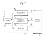
- each transponder 3 similarly comprises a control system 17, a transmitter 19, a receiver 21, a frequency synthesiser 23 which sets the operating frequency of the transmitter 19 and the receiver 21, a switch 25 and an antenna 27, connected as shown in Figure 3.
- the master station 1 and transponders 3 can each receive and transmit radio signals on any of the thirty-nine radio channels of the 888 to 889 MHz telemetry band (Department of Trade and Industry specification MPT 1341).
- each transponder 3 listens for a predetermined time on each of the thirty-nine channels of the 888 to 889 MHz telemetry band in turn.
- control system 17 instructs the switch 25 via a connection 41 to connect the antenna 27 to the receiver 21, and instructs the frequency synthesiser 23 via a connection 43 to step the receiver operating frequency through the thirty-nine channel frequencies of the 888 to 889 MHz telemetry band, remaining at each channel frequency for the required predetermined time.
- the frequency synthesisers 23 of the transponders 3 step randomly through the frequencies of the thirty-nine channels.
- the mobile master station 1 When the mobile master station 1 has positioned itself within radio range of a group of the transponders 3, it determines which of the thirty-nine channels of the 888-889 MHz telemetry band is the quietest, i.e. which channel of the band is being used the least by other users of the band. It then uses this quietest channel to attempt to communicate with the transponders 3.
- the master station 1 is within radio range of the transponders 3, its control system 5 instructs the switch 13 by way of a connection 29 to connect the receiver 9 to the antenna 15 and instructs the frequency synthesiser 11 by way of a connection 31 to step the receiver operating frequency in increasing order once through the channel frequencies of the 888-889 MHZ band, remaining at each frequency in the range for a preselected time.
- a signal representative of the strength of the signal received by the receiver 9 is passed, by way of a connection 33, to the control system 5 which determines the channel Q on which the weakest signal has been received, i.e. determines the quietest channel Q.
- the control system 5 of the master station 1 then instructs the switch 13 to connect the antenna 15 to the transmitter 7, causes the synthesiser 11 to set the transmitter operating frequency at the frequency of channel Q, and, via a connection 35, causes the transmitter 7 to transmit on channel Q a general wake-up signal to the transponders 3. Having transmitted the general wake-up signal the master station 1 then listens on channel Q.
- each of the receivers 21 of the transponders 3 that do receive the wake-up signal passes it via a connection 45 to the control system 17 which in response thereto: instructs the switch 25 to connect the antenna 27 to the transmitter 19; causes the synthesiser 25 to set the transmitter operating frequency of channel Q; and, via a connection 47, causes the transmitter 19 to transmit on channel Q an acknowledgement signal containing an address code unique to that transponder 3.
- the transponders 3 that have transmitted acknowledgement signals then listen for a defined period of time on channel Q. At the end of this defined period each transponder reverts to its initial state, i.e. the state in which it is listening for a perdetermined time on each of the thirty-nine channels in turn, unless within the defined period it has received from the master station 1 a signal containing its unique address code, as described below.
- the receiver 9 of the master station 1 receives on channel Q the strongest of the acknowledgement signals transmitted by the transponders 3 and passes the unique address code contained in that signal by way of a connection 37 to the control system 5.
- the control system 5 causes the transmitter 7 to transmit on channel Q a signal containing that unique address code. Having done this the master station 1 returns again to listening on channel Q.
- the control system 17 of one transponder causes that transponder to transmit to the master station on channel Q a signal containing data representing the electrical quantity held by it corresponding to an amount of electrical energy consumed as measured by the associated consumer's electricity meter.
- the receiver 9 of the master station 1 passes this information via the connection 37 to the control system 5 of the master station 1 where it is placed in memory as the reading for that meter.
- the master station 1 then transmits on channel Q to the relevant transponder 3 a signal instructing it to go to sleep for a time, so that it does not interfere with subsequent attempts by the master station 1 to communicate with other transponders 3 and hence read their associated meters.
- Such communication with the other transponders 3 takes place as described above, i.e. beginning with the transmission by the master station 1 of a general wake-up signal on channel Q and the response of all transponders 3 that are in radio range and are listening on channel Q at the time the wake-up signal is transmitted.
- the master station 1 transmits the wake-up call on the second, and if this fails, the third quietest channel as already determined. If communication is still not achieved the master station 1 re-determines which of the thirty-nine channels is the quietest channel and then recommences the above strategy. Re-determination of the quietest channel may also be made after a fixed time has passed since the preceding determination.
- the master station will repeat wake-up calls on a particular channel several times before changing to another channel, since failure to communicate with any transponder may be due to no transponders listening on the relevant channel. This situation can arise when only few transponders are in radio range and are not asleep.
- This problem may be alleviated by reducing the power with which the master station transmits the general wake-up signal so that fewer transponders are within radio range of the master station.
- it may be alleviated by the master station instructing the transponders within radio range to go to sleep for short random lengths of time so that they go to sleep for short different lengths of time. This reduces the potential number of replies to the next wake-up call and therefore reduces the probability of interference.
- the problem may also be alleviated by arranging for the transponders to listen in the stand-by mode non-continuously so that at any time only a fraction of the transponders within radio range of the master station can respond to a wake-up call. This problem can of course also be alleviated by the transponders using a form of modulation that minimises the probability of co-channel interference.
- the master station will normally be arranged to be capable of communicating with any desired particular transponder by transmitting a specific wake-up signal rather than a general wake-up signal.
- system may be arranged so that data can be passed from the master station to the transponders if desired for example, for setting the operating times of dual tariff electricity meters.
Abstract
A radio telemetry system for collecting the readings of consumer's electricity consumption meters comprising: a master station (1) carried by a vehicle (1) and a plurality of transponders (3), each of which holds an electrical quantity indicative of an amount of electrical power consumed as measured by a said meter associated with that transponder (3). The transponders (3) and the master station (1) communicate such that the transponders (3) transmit to the master station (1) signals containing information as to the values of the aforesaid electrical quantities held by them. Such communication takes place on a relatively quiet channel, of a number of channels, as determined by the master station (1) such that the system is capable of operating satisfactorily when the master station (1) and the transponders (3) utilise relatively low power transmitters (7, 19).
Description
- This invention relates to radio telemetry systems.
- More particular the invention relates to radio telemetry systems of the kind comprising a master station and a plurality of transponders which the master station interrogates so that data held by the transponders can be collected by the master station. Such a system finds application, for example, in collecting the readings of meters measuring the supply of a commodity, e.g. gas, water or electricity, to consumers.
- One known radio telemetry system of the above kind is disclosed in EP-A-245606. A disadvantage of this system is that for the system to operate satisfactorily the master station must utilise a relatively high power transmitter.
- It is an object of the present invention to provide a radio telemetry system wherein this disadvantage is overcome.
- According to the present invention there is provided a radio telemetry system comprising: a master station; and a plurality of transponders, said master station interrogating said transponders to collect data held by said transponders, characterised in that: each transponder has a stand-by state in which it listens on each of a number of channels in turn; the master station listens on each of said number of channels in turn to establish a relatively quiet channel and then transmits a wake-up signal on said relatively quiet channel; each transponder responds to receipt of a said wake-up signal by transmitting an acknowledgement signal on said relatively quiet channel; and the master station responds to receipt of an acknowledgement signal to receive data from the corresponding transponder, thereafter that transponder ignoring further wake-up signals for a predetermined time, and then transmits a further wake-up signal.
- One system in accordance with the present invention will now be described, by way of example, with reference to the accompanying drawings in which:-
- Figure 1 is a diagrammatic illustration of the system;
- Figure 2 is a block schematic diagram of a master station of the system; and
- Figure 3 is a block schematic diagram of a transponder of the system.
- Referring to Figure 1, the system comprises a master station carried by a road vehicle 1 and a plurality of
stationary transponders 3. Eachtransponder 3 is associated with a respective consumer's electricity meter (not shown) and holds an electrical quantity indicative of the amount of electrical energy consumed as measured by the associated meter. The master station 1 is mobile so that it can progressively position itself within radio range of different groups of thetransponders 3 for communication with them to obtain an indication of the electrical quantities held by them and thus remotely read their associated meters. - Referring to Figure 2, the master station 1 comprises a
control system 5, atransmitter 7, a receiver 9, a frequency synthesiser 11 which sets the operating frequency of thetransmitter 7 and the receiver 9, aswitch 13 and anantenna 15, connected as shown in Figure 2. - Referring to Figure 3, each
transponder 3 similarly comprises acontrol system 17, atransmitter 19, a receiver 21, afrequency synthesiser 23 which sets the operating frequency of thetransmitter 19 and the receiver 21, aswitch 25 and anantenna 27, connected as shown in Figure 3. - The operation of the system is as follows.
- The master station 1 and
transponders 3 can each receive and transmit radio signals on any of the thirty-nine radio channels of the 888 to 889 MHz telemetry band (Department of Trade and Industry specification MPT 1341). - In stand-by mode each
transponder 3 listens for a predetermined time on each of the thirty-nine channels of the 888 to 889 MHz telemetry band in turn. - More specifically, in each
transponder 3 thecontrol system 17 instructs theswitch 25 via aconnection 41 to connect theantenna 27 to the receiver 21, and instructs thefrequency synthesiser 23 via aconnection 43 to step the receiver operating frequency through the thirty-nine channel frequencies of the 888 to 889 MHz telemetry band, remaining at each channel frequency for the required predetermined time. - In order to minimise the number of
transponders 3 listening on any one channel at a given time, thefrequency synthesisers 23 of thetransponders 3 step randomly through the frequencies of the thirty-nine channels. - When the mobile master station 1 has positioned itself within radio range of a group of the
transponders 3, it determines which of the thirty-nine channels of the 888-889 MHz telemetry band is the quietest, i.e. which channel of the band is being used the least by other users of the band. It then uses this quietest channel to attempt to communicate with thetransponders 3. - More specifically, once the master station 1 is within radio range of the
transponders 3, itscontrol system 5 instructs theswitch 13 by way of aconnection 29 to connect the receiver 9 to theantenna 15 and instructs the frequency synthesiser 11 by way of aconnection 31 to step the receiver operating frequency in increasing order once through the channel frequencies of the 888-889 MHZ band, remaining at each frequency in the range for a preselected time. In respect of each channel a signal representative of the strength of the signal received by the receiver 9 is passed, by way of aconnection 33, to thecontrol system 5 which determines the channel Q on which the weakest signal has been received, i.e. determines the quietest channel Q. - The
control system 5 of the master station 1 then instructs theswitch 13 to connect theantenna 15 to thetransmitter 7, causes the synthesiser 11 to set the transmitter operating frequency at the frequency of channel Q, and, via aconnection 35, causes thetransmitter 7 to transmit on channel Q a general wake-up signal to thetransponders 3. Having transmitted the general wake-up signal the master station 1 then listens on channel Q. - As explained above, of the
transponders 3 in radio range of the master station only a small fraction will be listening on channel Q at the time the master station 1 transmits the wake-up signal, and will thus receive the wake-up signal. Each of the receivers 21 of thetransponders 3 that do receive the wake-up signal passes it via aconnection 45 to thecontrol system 17 which in response thereto: instructs theswitch 25 to connect theantenna 27 to thetransmitter 19; causes thesynthesiser 25 to set the transmitter operating frequency of channel Q; and, via aconnection 47, causes thetransmitter 19 to transmit on channel Q an acknowledgement signal containing an address code unique to thattransponder 3. - The
transponders 3 that have transmitted acknowledgement signals then listen for a defined period of time on channel Q. At the end of this defined period each transponder reverts to its initial state, i.e. the state in which it is listening for a perdetermined time on each of the thirty-nine channels in turn, unless within the defined period it has received from the master station 1 a signal containing its unique address code, as described below. - The receiver 9 of the master station 1 receives on channel Q the strongest of the acknowledgement signals transmitted by the
transponders 3 and passes the unique address code contained in that signal by way of aconnection 37 to thecontrol system 5. In response to receiving the unique address code of atransponder 3, thecontrol system 5 causes thetransmitter 7 to transmit on channel Q a signal containing that unique address code. Having done this the master station 1 returns again to listening on channel Q. - All the
transponders 3 that responded to the wake-up call will be listening at this time on channel Q and therefore receive this signal from the master station 1, but thecontrol system 17 of one transponder only will recognise this signal as containing its own unique address code. In response to such recognition, thecontrol system 17 of that transponder causes that transponder to transmit to the master station on channel Q a signal containing data representing the electrical quantity held by it corresponding to an amount of electrical energy consumed as measured by the associated consumer's electricity meter. The receiver 9 of the master station 1 passes this information via theconnection 37 to thecontrol system 5 of the master station 1 where it is placed in memory as the reading for that meter. - The master station 1 then transmits on channel Q to the relevant transponder 3 a signal instructing it to go to sleep for a time, so that it does not interfere with subsequent attempts by the master station 1 to communicate with
other transponders 3 and hence read their associated meters. - Such communication with the
other transponders 3 takes place as described above, i.e. beginning with the transmission by the master station 1 of a general wake-up signal on channel Q and the response of alltransponders 3 that are in radio range and are listening on channel Q at the time the wake-up signal is transmitted. - In the instance where there is a failure to communicate on channel Q, the master station 1 transmits the wake-up call on the second, and if this fails, the third quietest channel as already determined. If communication is still not achieved the master station 1 re-determines which of the thirty-nine channels is the quietest channel and then recommences the above strategy. Re-determination of the quietest channel may also be made after a fixed time has passed since the preceding determination.
- The master station will repeat wake-up calls on a particular channel several times before changing to another channel, since failure to communicate with any transponder may be due to no transponders listening on the relevant channel. This situation can arise when only few transponders are in radio range and are not asleep.
- It will be appreciated that satisfactory operation of the system requires the master station to be able to pick out from the acknowledgement signals sent by the transponders in response to a wake-up call, one particular acknowledgement signal. Whilst this presents no problem where one acknowledgement signal is stronger than the others, where a relatively large number of transponder units are in radio range of the master station, interference between acknowledgement signals may prevent the master station from satisfactorily receiving any acknowledgement signal.
- This problem may be alleviated by reducing the power with which the master station transmits the general wake-up signal so that fewer transponders are within radio range of the master station. Alternatively it may be alleviated by the master station instructing the transponders within radio range to go to sleep for short random lengths of time so that they go to sleep for short different lengths of time. This reduces the potential number of replies to the next wake-up call and therefore reduces the probability of interference. The problem may also be alleviated by arranging for the transponders to listen in the stand-by mode non-continuously so that at any time only a fraction of the transponders within radio range of the master station can respond to a wake-up call. This problem can of course also be alleviated by the transponders using a form of modulation that minimises the probability of co-channel interference.
- It will be appreciated that this interference problem arises especially when the master station first starts transmitting in a new locality. Re-occurrence of the problem when all transponders within radio range have been interogated can be avoided by the master station then moving its position only slightly so that when the next wake-up call is made only relatively few transponders are in radio range and not asleep.
- It will be understood that the master station will normally be arranged to be capable of communicating with any desired particular transponder by transmitting a specific wake-up signal rather than a general wake-up signal.
- Similarly, the system may be arranged so that data can be passed from the master station to the transponders if desired for example, for setting the operating times of dual tariff electricity meters.
Claims (12)
1. A radio telemetry system comprising: a master station (1); and a plurality of transponders (3), said master station (1) interrogating said transponders (3) to collect data held by said transponders (3), characterised in that: each transponder (3) has a stand-by state in which it listens on each of a number of channels in turn; the master station (1) listens on each of said number of channels in turn to establish a relatively quiet channel and then transmits a wake-up signal on said relatively quiet channel; each transponder (3) responds to receipt of a said wake-up signal by transmitting an acknowledgement signal on said relatively quiet channel; and the master station (1) responds to receipt of an acknowledgement signal to receive data from the corresponding transponder (3), thereafter that transponder (3) ignoring further wake-up signals for a predetermined time, and then transmits a further wake-up signal.
2. A system according to Claim 1 wherein said master station (1) instructs said corresponding transponder (3) to ignore said further wake-up signals.
3. A system according to Claim 1 or Claim 2 wherein said relatively quiet channel is the quietest channel.
4. A system according to Claim 3 wherein, if said master station (1) fails to receive an acknowledgement signal in response to its transmitting a wake-up signal, the master station (1) transmits a wake-up signal on the second quietest channel.
5. A system according to any one of the preceding claims wherein, if said master station (1) fails to receive an acknowledgement signal in response to its transmitting a wake-up signal, the master station (1) listens again on each of said number of channels in turn to establish a relatively quiet channel and transmits a wake-up signal on this relatively quiet channel.
6. A system according to any one of the preceding claims wherein, if the master station (1) fails to receive an acknowledgement signal in response to its transmitting a wake-up signal, the master station (1) reduces the power with which it transmits the wake-up signal.
7. A system according to any one of the preceding claims wherein, if the master station (1) fails to receive an acknowledgement signal in response to its transmitting a wake-up signal, the master station (1) instructs the transponders (3) within radio range to go to sleep for short random lengths of time.
8. A system according to any one of the preceding claims wherein each transponder (3) listens in the standby state non-continuously.
9. A system according to any one of the preceding claims wherein said master station (1) is carried by a vehicle (1); and, once all the transponders (3) within radio range are ignoring further wake-up signals for a predetermined time, the vehicle (1) moves the master station's position so that only relatively few transponders (3) are in radio range and not ignoring wake-up signals.
10. A system according to any one of the preceding claims wherein the data received from each transponder (3) represents a quantity determined by monitoring means associated with that transponder (3).
11. A system according to Claim 10 wherein the quantity is the amount of a commodity supplied to a consumer.
12. A system according to Claim 11 wherein said commodity is electrical energy, each monitoring means comprising a respective consumer's electricity consumption meter.
Applications Claiming Priority (2)
| Application Number | Priority Date | Filing Date | Title |
|---|---|---|---|
| GB8925907A GB2238147B (en) | 1989-11-16 | 1989-11-16 | Radio telemetry systems |
| GB8925907 | 1989-11-16 |
Publications (1)
| Publication Number | Publication Date |
|---|---|
| EP0428322A1 true EP0428322A1 (en) | 1991-05-22 |
Family
ID=10666403
Family Applications (1)
| Application Number | Title | Priority Date | Filing Date |
|---|---|---|---|
| EP90312173A Withdrawn EP0428322A1 (en) | 1989-11-16 | 1990-11-07 | Radio telemetry system |
Country Status (5)
| Country | Link |
|---|---|
| US (1) | US5194860A (en) |
| EP (1) | EP0428322A1 (en) |
| GB (1) | GB2238147B (en) |
| NZ (1) | NZ236036A (en) |
| ZA (1) | ZA909013B (en) |
Cited By (13)
| Publication number | Priority date | Publication date | Assignee | Title |
|---|---|---|---|---|
| DE4225042A1 (en) * | 1992-07-29 | 1994-02-03 | Ziegler Horst | Method for transferring measurement data |
| DE4235187A1 (en) * | 1992-10-19 | 1994-04-21 | Metrona Waermemesser Union | Device for reading consumption values occurring in a building |
| DE4321037A1 (en) * | 1993-06-24 | 1995-02-02 | Detecon Gmbh | Method for detecting (measuring) and transmitting measured values, using an information-processing system, and device for carrying out the method |
| WO1995027273A1 (en) * | 1994-03-31 | 1995-10-12 | David Bell | Telemetry |
| WO1996036028A1 (en) * | 1995-05-12 | 1996-11-14 | Marposs Societa' Per Azioni | System and method for the wireless signal transmission for checking probes |
| WO1997029571A1 (en) * | 1996-02-12 | 1997-08-14 | Hewlett-Packard Company | Signal transmission between networked computers |
| FR2762110A1 (en) * | 1997-04-14 | 1998-10-16 | Renishaw Plc | PROGRAMMABLE SENSOR FORMING SYSTEM |
| WO2000038126A1 (en) * | 1998-12-22 | 2000-06-29 | Satsafe Mls Ab | Low effect communication apparatus and system for achieving reduced power consumption |
| EP1598991A1 (en) * | 2002-01-03 | 2005-11-23 | VKR Holding A/S | Method of and system for transmitting signals using frequency hopping |
| WO2006056451A1 (en) * | 2004-11-26 | 2006-06-01 | Giesecke & Devrient Gmbh | Communication device |
| WO2008012041A1 (en) * | 2006-07-25 | 2008-01-31 | Diehl Ako Stiftung & Co. Kg | Photovoltaic arrangement |
| US8155061B2 (en) | 2002-01-03 | 2012-04-10 | Vkr Holding A/S | Method of and system for transmitting signals using frequency hopping |
| GB2591513A (en) * | 2020-01-31 | 2021-08-04 | Agd Systems Ltd | Traffic signal system and method |
Families Citing this family (123)
| Publication number | Priority date | Publication date | Assignee | Title |
|---|---|---|---|---|
| US5640151A (en) * | 1990-06-15 | 1997-06-17 | Texas Instruments Incorporated | Communication system for communicating with tags |
| US5973613A (en) * | 1990-06-15 | 1999-10-26 | Raytheon Company | Personal messaging system and method |
| US5528232A (en) * | 1990-06-15 | 1996-06-18 | Savi Technology, Inc. | Method and apparatus for locating items |
| GB9104881D0 (en) * | 1991-03-08 | 1991-04-24 | Ind Cybernetics Ltd | Monitoring apparatus and system |
| DK52091D0 (en) * | 1991-03-22 | 1991-03-22 | Esel Krabbe Systems As | INFORMATION |
| US5376930A (en) * | 1992-04-22 | 1994-12-27 | Maytag Corporation | Data acquisition system having selective communication capability |
| US5365551A (en) * | 1992-12-15 | 1994-11-15 | Micron Technology, Inc. | Data communication transceiver using identification protocol |
| US5500650A (en) * | 1992-12-15 | 1996-03-19 | Micron Technology, Inc. | Data communication method using identification protocol |
| US7158031B2 (en) | 1992-08-12 | 2007-01-02 | Micron Technology, Inc. | Thin, flexible, RFID label and system for use |
| US6097301A (en) * | 1996-04-04 | 2000-08-01 | Micron Communications, Inc. | RF identification system with restricted range |
| US20050040961A1 (en) * | 1995-04-11 | 2005-02-24 | Tuttle John R. | RF identification system with restricted range |
| US5963872A (en) * | 1993-03-04 | 1999-10-05 | Telefonaktiebolaget Lm Ericsson (Publ) | Electronic equipment audio system |
| US6016432A (en) * | 1993-03-04 | 2000-01-18 | Telefonaktiebolaget L/M Ericsson (Publ) | Electronic metering equipment system |
| US5905947A (en) * | 1993-03-04 | 1999-05-18 | Telefonaktiebolaget Lm Ericsson | Electronic audio system capable of communicating data signals over wireless networks |
| US5890074A (en) * | 1993-03-04 | 1999-03-30 | Telefonaktiebolaget L M Ericsson | Modular unit headset |
| US5438329A (en) * | 1993-06-04 | 1995-08-01 | M & Fc Holding Company, Inc. | Duplex bi-directional multi-mode remote instrument reading and telemetry system |
| US5790946A (en) * | 1993-07-15 | 1998-08-04 | Rotzoll; Robert R. | Wake up device for a communications system |
| US5754122A (en) * | 1993-07-19 | 1998-05-19 | Competitive Technologies, Inc. | System and method for monitoring structures |
| US5617084A (en) * | 1993-09-10 | 1997-04-01 | Sears; Lawrence M. | Apparatus for communicating utility usage-related information from a utility usage location to a utility usage registering device |
| US5608171A (en) * | 1993-11-16 | 1997-03-04 | Hunter; Robert M. | Distributed, unattended wastewater monitoring system |
| US5493722A (en) * | 1994-01-24 | 1996-02-20 | Ingersoll-Rand Company | Method for controlling data transmissions on a single channel radio frequency network |
| WO1995024027A1 (en) * | 1994-03-04 | 1995-09-08 | Motorola Inc. | Remote meter reading power reduction method |
| US5493287A (en) * | 1994-03-07 | 1996-02-20 | Motorola, Inc. | Method of remotely reading a group of meters |
| AU2200895A (en) * | 1994-04-04 | 1995-10-23 | Motorola, Inc. | Method and apparatus for activating and accessing remote meter interface devices |
| US5481259A (en) * | 1994-05-02 | 1996-01-02 | Motorola, Inc. | Method for reading a plurality of remote meters |
| US5495239A (en) * | 1994-08-02 | 1996-02-27 | General Electric Company | Method and apparatus for communicating with a plurality of electrical metering devices and a system control center with a mobile node |
| DE19514223B4 (en) * | 1995-04-15 | 2005-06-23 | Claas Kgaa Mbh | Method for optimizing the use of agricultural machinery |
| US5719563A (en) * | 1995-07-07 | 1998-02-17 | Teletrac, Inc. | Fixed site monitor using a location-based communications network |
| US5802454A (en) * | 1995-12-15 | 1998-09-01 | Teletrac, Inc. | Remotely distributed location and messaging system |
| US6489884B1 (en) * | 1996-01-30 | 2002-12-03 | Skf Condition Monitoring | Apparatus and method for the remote monitoring of machine condition |
| US5850187A (en) * | 1996-03-27 | 1998-12-15 | Amtech Corporation | Integrated electronic tag reader and wireless communication link |
| US6078251A (en) * | 1996-03-27 | 2000-06-20 | Intermec Ip Corporation | Integrated multi-meter and wireless communication link |
| US5801643A (en) * | 1996-06-20 | 1998-09-01 | Northrop Grumman Corporation | Remote utility meter reading system |
| US6124800A (en) * | 1996-08-21 | 2000-09-26 | Intermec Ip Corp. | Radio-frequency LAN and WAN communication system for route delivery applications or the like |
| US6362737B1 (en) | 1998-06-02 | 2002-03-26 | Rf Code, Inc. | Object Identification system with adaptive transceivers and methods of operation |
| CA2268951A1 (en) | 1996-10-17 | 1998-04-23 | Pinpoint Corporation | Article tracking system |
| US6812824B1 (en) | 1996-10-17 | 2004-11-02 | Rf Technologies, Inc. | Method and apparatus combining a tracking system and a wireless communication system |
| US6246883B1 (en) * | 1996-12-24 | 2001-06-12 | Lucent Technologies, Inc. | Mobile base station |
| AR011440A1 (en) * | 1997-02-12 | 2000-08-16 | Abb Power T & D Co | ELECTRONIC MEASUREMENT PROVISION |
| US7046682B2 (en) * | 1997-02-12 | 2006-05-16 | Elster Electricity, Llc. | Network-enabled, extensible metering system |
| US6073169A (en) * | 1997-04-08 | 2000-06-06 | Abb Power T&D Company Inc. | Automatic meter reading system employing common broadcast command channel |
| US6119076A (en) | 1997-04-16 | 2000-09-12 | A.L. Air Data, Inc. | Lamp monitoring and control unit and method |
| US6359555B1 (en) | 1997-04-16 | 2002-03-19 | A.L. Airdata, Inc. | Alarm monitoring and control system and method |
| US6714895B2 (en) * | 2000-06-28 | 2004-03-30 | A.L. Air Data, Inc. | Lamp monitoring and control unit and method |
| US6035266A (en) * | 1997-04-16 | 2000-03-07 | A.L. Air Data, Inc. | Lamp monitoring and control system and method |
| US5963650A (en) * | 1997-05-01 | 1999-10-05 | Simionescu; Dan | Method and apparatus for a customizable low power RF telemetry system with high performance reduced data rate |
| US5936972A (en) * | 1997-06-18 | 1999-08-10 | Motorola, Inc. | Syndrome-based channel quality or message structure determiner |
| US6339385B1 (en) | 1997-08-20 | 2002-01-15 | Micron Technology, Inc. | Electronic communication devices, methods of forming electrical communication devices, and communication methods |
| US6088659A (en) * | 1997-09-11 | 2000-07-11 | Abb Power T&D Company Inc. | Automated meter reading system |
| AU9480798A (en) | 1997-09-12 | 1999-03-29 | Williams Wireless, Inc. | Wide area remote telemetry |
| IT1295471B1 (en) * | 1997-10-03 | 1999-05-12 | Taglioni Communications S A S | SYSTEM FOR DETECTION OF DOMESTIC CONSUMPTION OF ELECTRICITY, THERMAL ENERGY, WATER AND GAS. |
| US6337971B1 (en) | 1997-10-14 | 2002-01-08 | Gerald L. Abts | System for controlling and monitoring agricultural field equipment and method |
| US6118789A (en) | 1998-02-19 | 2000-09-12 | Micron Technology, Inc. | Method of addressing messages and communications system |
| US6275476B1 (en) | 1998-02-19 | 2001-08-14 | Micron Technology, Inc. | Method of addressing messages and communications system |
| USRE43382E1 (en) | 1998-02-19 | 2012-05-15 | Round Rock Research, Llc | Method of addressing messages and communications systems |
| US6072801A (en) | 1998-02-19 | 2000-06-06 | Micron Technology, Inc. | Method of addressing messages, method of establishing wireless communications, and communications system |
| US6061344A (en) | 1998-02-19 | 2000-05-09 | Micron Technology, Inc. | Method of addressing messages and communications system |
| CA2325923A1 (en) | 1998-03-24 | 1999-09-30 | Bellsouth Intellectual Property Corporation | Wireless telemetry methods and systems for communicating with or controlling intelligent devices |
| US6700902B1 (en) | 1998-10-19 | 2004-03-02 | Elster Electricity, Llc | Method and system for improving wireless data packet delivery |
| US6714121B1 (en) * | 1999-08-09 | 2004-03-30 | Micron Technology, Inc. | RFID material tracking method and apparatus |
| US7061398B2 (en) * | 1999-08-16 | 2006-06-13 | Bs&B Safety Systems Limited | Two-way wide area telemetry |
| US6933857B2 (en) * | 2000-05-05 | 2005-08-23 | Charles A. Foote | Method and system for airborne meter communication |
| WO2002025987A2 (en) * | 2000-09-21 | 2002-03-28 | James Robert Orlosky | Automated meter reading, billing, and payment processing system |
| JP3860116B2 (en) * | 2000-10-31 | 2006-12-20 | ミレニアル・ネット・インコーポレーテッド | Network processing system with optimized power efficiency |
| US7385524B1 (en) | 2001-09-21 | 2008-06-10 | James Robert Orlosky | Automated meter reading, billing and payment processing system |
| AU2002352922A1 (en) | 2001-11-28 | 2003-06-10 | Millennial Net | Etwork protocol for an ad hoc wireless network |
| US6867707B1 (en) | 2002-04-24 | 2005-03-15 | Elster Electricity, Llc | Automated on-site meter registration confirmation using a portable, wireless computing device |
| US7119713B2 (en) * | 2002-06-27 | 2006-10-10 | Elster Electricity, Llc | Dynamic self-configuring metering network |
| US20040113810A1 (en) * | 2002-06-28 | 2004-06-17 | Mason Robert T. | Data collector for an automated meter reading system |
| US7313399B2 (en) * | 2003-06-05 | 2007-12-25 | Millennial Net, Inc. | Protocol for configuring a wireless network |
| US7336200B2 (en) * | 2003-09-05 | 2008-02-26 | Itron, Inc. | Data communication protocol in an automatic meter reading system |
| AU2003270323A1 (en) * | 2003-09-05 | 2005-04-21 | Itron, Inc. | Field data collection and processing system, such as for electric, gas, and water utility data |
| US20050086182A1 (en) * | 2003-09-05 | 2005-04-21 | Christopher Nagy | Optimized bubble up receiver AMR system |
| CA2485595A1 (en) * | 2003-10-21 | 2005-04-21 | Itron, Inc. | Combined scheduling and management of work orders, such as for utility meter reading and utility servicing events |
| JP2005158161A (en) * | 2003-11-26 | 2005-06-16 | Mitsumi Electric Co Ltd | Objective lens driving apparatus |
| US7227350B2 (en) * | 2004-03-18 | 2007-06-05 | Elster Electricity, Llc | Bias technique for electric utility meter |
| US7315162B2 (en) * | 2004-03-18 | 2008-01-01 | Elster Electricity, Llc | Reducing power consumption of electrical meters |
| US7187906B2 (en) * | 2004-04-26 | 2007-03-06 | Elster Electricity, Llc | Method and system for configurable qualification and registration in a fixed network automated meter reading system |
| US20050237959A1 (en) * | 2004-04-26 | 2005-10-27 | Christopher Osterloh | Mobile automatic meter reading system and method |
| US7262709B2 (en) * | 2004-04-26 | 2007-08-28 | Elster Electricity, Llc | System and method for efficient configuration in a fixed network automated meter reading system |
| US7239250B2 (en) * | 2004-04-26 | 2007-07-03 | Elster Electricity, Llc | System and method for improved transmission of meter data |
| US20050251403A1 (en) * | 2004-05-10 | 2005-11-10 | Elster Electricity, Llc. | Mesh AMR network interconnecting to TCP/IP wireless mesh network |
| US20050251401A1 (en) * | 2004-05-10 | 2005-11-10 | Elster Electricity, Llc. | Mesh AMR network interconnecting to mesh Wi-Fi network |
| US20050267898A1 (en) * | 2004-05-28 | 2005-12-01 | Robert Simon | Data format and method for communicating data associated with utility applications, such as for electric, gas, and water utility applications |
| US7142106B2 (en) * | 2004-06-15 | 2006-11-28 | Elster Electricity, Llc | System and method of visualizing network layout and performance characteristics in a wireless network |
| US7283062B2 (en) * | 2004-07-28 | 2007-10-16 | Itron, Inc. | Mapping in mobile data collection systems, such as for utility meter reading and related applications |
| US7702594B2 (en) * | 2004-09-24 | 2010-04-20 | Elster Electricity, Llc | System and method for automated configuration of meters |
| US7170425B2 (en) * | 2004-09-24 | 2007-01-30 | Elster Electricity, Llc | System and method for creating multiple operating territories within a meter reading system |
| US7176807B2 (en) * | 2004-09-24 | 2007-02-13 | Elster Electricity, Llc | System for automatically enforcing a demand reset in a fixed network of electricity meters |
| US7742430B2 (en) * | 2004-09-24 | 2010-06-22 | Elster Electricity, Llc | System for automated management of spontaneous node migration in a distributed fixed wireless network |
| US20060074601A1 (en) * | 2004-10-01 | 2006-04-06 | Itron, Inc. | Endpoint location file format, such as for use in mapping endpoints in a utility meter reading system |
| US20060167638A1 (en) * | 2004-11-04 | 2006-07-27 | Murphy Jonathan D M | Data collector with wireless server connection |
| US7327998B2 (en) * | 2004-12-22 | 2008-02-05 | Elster Electricity, Llc | System and method of providing a geographic view of nodes in a wireless network |
| US20060206433A1 (en) * | 2005-03-11 | 2006-09-14 | Elster Electricity, Llc. | Secure and authenticated delivery of data from an automated meter reading system |
| US20060224335A1 (en) * | 2005-03-29 | 2006-10-05 | Elster Electricity, Llc | Collecting interval data from a relative time battery powered automated meter reading devices |
| KR20080025095A (en) * | 2005-06-01 | 2008-03-19 | 밀레니얼 넷, 인크. | Communicating over a wireless network |
| US7495578B2 (en) * | 2005-09-02 | 2009-02-24 | Elster Electricity, Llc | Multipurpose interface for an automated meter reading device |
| US7535378B2 (en) * | 2005-09-09 | 2009-05-19 | Itron, Inc. | RF meter reading system |
| US20070057813A1 (en) * | 2005-09-09 | 2007-03-15 | Cahill-O'brien Barry | RF meter reading network with wake-up tone calibrated endpoints |
| US7308369B2 (en) * | 2005-09-28 | 2007-12-11 | Elster Electricity Llc | Ensuring automatic season change demand resets in a mesh type network of telemetry devices |
| US20070147268A1 (en) * | 2005-12-23 | 2007-06-28 | Elster Electricity, Llc | Distributing overall control of mesh AMR LAN networks to WAN interconnected collectors |
| US7830874B2 (en) * | 2006-02-03 | 2010-11-09 | Itron, Inc. | Versatile radio packeting for automatic meter reading systems |
| US7545285B2 (en) * | 2006-02-16 | 2009-06-09 | Elster Electricity, Llc | Load control unit in communication with a fixed network meter reading system |
| US7427927B2 (en) * | 2006-02-16 | 2008-09-23 | Elster Electricity, Llc | In-home display communicates with a fixed network meter reading system |
| US8073384B2 (en) * | 2006-12-14 | 2011-12-06 | Elster Electricity, Llc | Optimization of redundancy and throughput in an automated meter data collection system using a wireless network |
| WO2008086231A2 (en) * | 2007-01-04 | 2008-07-17 | Itron, Inc. | Utility data collection and reconfigurations in a utility metering system |
| US7973644B2 (en) | 2007-01-30 | 2011-07-05 | Round Rock Research, Llc | Systems and methods for RFID tag arbitration where RFID tags generate multiple random numbers for different arbitration sessions |
| US20080212303A1 (en) * | 2007-03-02 | 2008-09-04 | Warren Farnworth | Device for reducing or preventing exchange of information |
| US8320302B2 (en) * | 2007-04-20 | 2012-11-27 | Elster Electricity, Llc | Over the air microcontroller flash memory updates |
| US8134452B2 (en) * | 2007-05-30 | 2012-03-13 | Round Rock Research, Llc | Methods and systems of receiving data payload of RFID tags |
| JP4698755B2 (en) * | 2007-06-27 | 2011-06-08 | 富士通株式会社 | Information access system, contactless read / write device, and contactless information storage device |
| WO2009082761A1 (en) | 2007-12-26 | 2009-07-02 | Elster Electricity, Llc. | Optimized data collection in a wireless fixed network metering system |
| US20100026517A1 (en) * | 2008-01-04 | 2010-02-04 | Itron, Inc. | Utility data collection and reconfigurations in a utility metering system |
| US8525692B2 (en) * | 2008-06-13 | 2013-09-03 | Elster Solutions, Llc | Techniques for limiting demand from an electricity meter with an installed relay |
| US8730056B2 (en) | 2008-11-11 | 2014-05-20 | Itron, Inc. | System and method of high volume import, validation and estimation of meter data |
| US20100265095A1 (en) * | 2009-04-20 | 2010-10-21 | Itron, Inc. | Endpoint classification and command processing |
| US8436744B2 (en) * | 2009-01-29 | 2013-05-07 | Itron, Inc. | Prioritized collection of meter readings |
| US8203463B2 (en) | 2009-02-13 | 2012-06-19 | Elster Electricity Llc | Wakeup and interrogation of meter-reading devices using licensed narrowband and unlicensed wideband radio communication |
| US8269650B2 (en) | 2010-04-14 | 2012-09-18 | Itron, Inc. | Meter right sizing |
| US9915688B2 (en) * | 2013-12-09 | 2018-03-13 | Dataflyte, Inc. | Airborne data collection |
| TWI549088B (en) * | 2015-03-19 | 2016-09-11 | Electricity charging method | |
| CN105608863A (en) * | 2015-11-03 | 2016-05-25 | 四川省科建煤炭产业技术研究院有限公司 | Mining-used wireless ad hoc network gas drainage pipeline measuring method |
| CN108811047A (en) | 2017-04-26 | 2018-11-13 | 华为技术有限公司 | The method that wireless access point, terminal device and wireless access point wake up terminal device |
Citations (3)
| Publication number | Priority date | Publication date | Assignee | Title |
|---|---|---|---|---|
| US4197500A (en) * | 1976-11-01 | 1980-04-08 | The United States Of America As Represented By The Secretary Of The Army | Automatic channel selection |
| EP0189920A2 (en) * | 1985-01-31 | 1986-08-06 | Nec Corporation | Radio channel control method for mobile communication system |
| EP0245606A2 (en) * | 1986-03-14 | 1987-11-19 | EnScan, Inc. | Automatic/remote RF instrument reading system |
Family Cites Families (3)
| Publication number | Priority date | Publication date | Assignee | Title |
|---|---|---|---|---|
| FR2414841A1 (en) * | 1978-01-13 | 1979-08-10 | Trt Telecom Radio Electr | RECEPTION SYSTEM FOR SENDING, TO A CENTRAL STATION, INFORMATION SENT BY A MOBILE TRANSMITTER |
| US4309773A (en) * | 1980-04-18 | 1982-01-05 | The United States Of America As Represented By The Secretary Of The Navy | Apparatus and method for radio channel selection |
| US4614945A (en) * | 1985-02-20 | 1986-09-30 | Diversified Energies, Inc. | Automatic/remote RF instrument reading method and apparatus |
-
1989
- 1989-11-16 GB GB8925907A patent/GB2238147B/en not_active Expired - Fee Related
-
1990
- 1990-11-07 EP EP90312173A patent/EP0428322A1/en not_active Withdrawn
- 1990-11-09 ZA ZA909013A patent/ZA909013B/en unknown
- 1990-11-12 NZ NZ236036A patent/NZ236036A/en unknown
- 1990-11-15 US US07/613,319 patent/US5194860A/en not_active Expired - Fee Related
Patent Citations (3)
| Publication number | Priority date | Publication date | Assignee | Title |
|---|---|---|---|---|
| US4197500A (en) * | 1976-11-01 | 1980-04-08 | The United States Of America As Represented By The Secretary Of The Army | Automatic channel selection |
| EP0189920A2 (en) * | 1985-01-31 | 1986-08-06 | Nec Corporation | Radio channel control method for mobile communication system |
| EP0245606A2 (en) * | 1986-03-14 | 1987-11-19 | EnScan, Inc. | Automatic/remote RF instrument reading system |
Non-Patent Citations (1)
| Title |
|---|
| IEEE TRANSACTIONS ON POWER DELIVERY. vol. PRWD2, no. 3, July 1987, NEW YORK US pages 671 - 676; J.T.LANCASTER et al: "SEMI-AUTOMATIC METER READING" * |
Cited By (20)
| Publication number | Priority date | Publication date | Assignee | Title |
|---|---|---|---|---|
| DE4225042A1 (en) * | 1992-07-29 | 1994-02-03 | Ziegler Horst | Method for transferring measurement data |
| DE4235187A1 (en) * | 1992-10-19 | 1994-04-21 | Metrona Waermemesser Union | Device for reading consumption values occurring in a building |
| DE4321037A1 (en) * | 1993-06-24 | 1995-02-02 | Detecon Gmbh | Method for detecting (measuring) and transmitting measured values, using an information-processing system, and device for carrying out the method |
| DE4321037C2 (en) * | 1993-06-24 | 2002-06-06 | T Mobile Deutschland Gmbh | Method for acquiring and transmitting measured values using an information processing system and device for carrying out the method |
| US5852409A (en) * | 1994-03-31 | 1998-12-22 | Bell; David | Telemetry |
| GB2302198B (en) * | 1994-03-31 | 1998-04-15 | David Bell | Telemetry |
| GB2302198A (en) * | 1994-03-31 | 1997-01-08 | David Bell | Telemetry |
| WO1995027273A1 (en) * | 1994-03-31 | 1995-10-12 | David Bell | Telemetry |
| US6115647A (en) * | 1995-05-12 | 2000-09-05 | Marposs Societa'per Azioni | System and method for the wireless signal transmission for checking probes |
| WO1996036028A1 (en) * | 1995-05-12 | 1996-11-14 | Marposs Societa' Per Azioni | System and method for the wireless signal transmission for checking probes |
| WO1997029571A1 (en) * | 1996-02-12 | 1997-08-14 | Hewlett-Packard Company | Signal transmission between networked computers |
| FR2762110A1 (en) * | 1997-04-14 | 1998-10-16 | Renishaw Plc | PROGRAMMABLE SENSOR FORMING SYSTEM |
| US6301796B1 (en) | 1997-04-14 | 2001-10-16 | Renishaw Plc | Programmable probe system |
| EP0872787A1 (en) * | 1997-04-14 | 1998-10-21 | Renishaw plc | Programmable probe system |
| WO2000038126A1 (en) * | 1998-12-22 | 2000-06-29 | Satsafe Mls Ab | Low effect communication apparatus and system for achieving reduced power consumption |
| EP1598991A1 (en) * | 2002-01-03 | 2005-11-23 | VKR Holding A/S | Method of and system for transmitting signals using frequency hopping |
| US8155061B2 (en) | 2002-01-03 | 2012-04-10 | Vkr Holding A/S | Method of and system for transmitting signals using frequency hopping |
| WO2006056451A1 (en) * | 2004-11-26 | 2006-06-01 | Giesecke & Devrient Gmbh | Communication device |
| WO2008012041A1 (en) * | 2006-07-25 | 2008-01-31 | Diehl Ako Stiftung & Co. Kg | Photovoltaic arrangement |
| GB2591513A (en) * | 2020-01-31 | 2021-08-04 | Agd Systems Ltd | Traffic signal system and method |
Also Published As
| Publication number | Publication date |
|---|---|
| ZA909013B (en) | 1991-08-28 |
| NZ236036A (en) | 1992-11-25 |
| GB2238147B (en) | 1993-04-21 |
| GB8925907D0 (en) | 1990-01-04 |
| US5194860A (en) | 1993-03-16 |
| GB2238147A (en) | 1991-05-22 |
Similar Documents
| Publication | Publication Date | Title |
|---|---|---|
| US5194860A (en) | Radio telemetry systems with channel selection | |
| CA1290402C (en) | Radio communication system having means for avoiding signal collision | |
| EP1671210B1 (en) | Method and system for improved wlan location | |
| US6246677B1 (en) | Automatic meter reading data communication system | |
| US5631636A (en) | Method of reducing power consumption in a remote meter reading system | |
| EP0420180B1 (en) | Transponder for vehicle identification device | |
| US4630314A (en) | Meteor burst communication system | |
| US7061398B2 (en) | Two-way wide area telemetry | |
| US20040038677A1 (en) | Location finding system and method | |
| WO1995027272A1 (en) | Method and apparatus for activating and accessing remote meter interface devices | |
| WO1998010394A1 (en) | Automatic meter reading data communication system | |
| EP0056686A3 (en) | Access control card | |
| CA2174912A1 (en) | Transmission Diversity System | |
| JPH08511667A (en) | Dual bidirectional multimode remote meter reading and telemetry system | |
| CA1301379C (en) | Multiple accessing satellite communication system having standby central station | |
| WO2003061149A1 (en) | Frequency hopping spread spectrum communications system | |
| EP2537120B1 (en) | Method and apparatus for discrimination of rfid tags | |
| WO1981002960A1 (en) | Control unit for automatic meter reading system | |
| US7587195B2 (en) | Wireless communications apparatus made operative in dependent upon a received signal strength | |
| WO2014088961A2 (en) | Multi-tone wakeup mechanism for a wireless network | |
| CN111431559A (en) | Internet of things awakening and data transmission device and method | |
| EP1062831B1 (en) | Method and system for transmitting data | |
| JPH07140236A (en) | Radio response system | |
| EP2171637A1 (en) | Radio frequency identification system provided for access control | |
| EP1127415B1 (en) | Battery economising in a communications system |
Legal Events
| Date | Code | Title | Description |
|---|---|---|---|
| PUAI | Public reference made under article 153(3) epc to a published international application that has entered the european phase |
Free format text: ORIGINAL CODE: 0009012 |
|
| AK | Designated contracting states |
Kind code of ref document: A1 Designated state(s): BE CH DE ES FR GB IT LI SE |
|
| 17P | Request for examination filed |
Effective date: 19911120 |
|
| 17Q | First examination report despatched |
Effective date: 19940330 |
|
| STAA | Information on the status of an ep patent application or granted ep patent |
Free format text: STATUS: THE APPLICATION IS DEEMED TO BE WITHDRAWN |
|
| 18D | Application deemed to be withdrawn |
Effective date: 19950606 |