EP0427376A2 - Membrane separation system and method of operation - Google Patents
Membrane separation system and method of operation Download PDFInfo
- Publication number
- EP0427376A2 EP0427376A2 EP90308157A EP90308157A EP0427376A2 EP 0427376 A2 EP0427376 A2 EP 0427376A2 EP 90308157 A EP90308157 A EP 90308157A EP 90308157 A EP90308157 A EP 90308157A EP 0427376 A2 EP0427376 A2 EP 0427376A2
- Authority
- EP
- European Patent Office
- Prior art keywords
- conduit
- separation module
- junction
- valved
- junctions
- Prior art date
- Legal status (The legal status is an assumption and is not a legal conclusion. Google has not performed a legal analysis and makes no representation as to the accuracy of the status listed.)
- Ceased
Links
- 238000000034 method Methods 0.000 title claims abstract description 117
- 238000000926 separation method Methods 0.000 title claims abstract description 87
- 239000012528 membrane Substances 0.000 title claims description 59
- 239000000706 filtrate Substances 0.000 claims abstract description 23
- 239000000725 suspension Substances 0.000 claims abstract description 10
- 239000002245 particle Substances 0.000 claims abstract description 9
- 230000008569 process Effects 0.000 claims description 95
- 239000012530 fluid Substances 0.000 claims description 66
- 239000012466 permeate Substances 0.000 claims description 44
- 238000004140 cleaning Methods 0.000 claims description 13
- 239000012141 concentrate Substances 0.000 claims description 12
- 238000005086 pumping Methods 0.000 claims description 10
- 238000000108 ultra-filtration Methods 0.000 claims description 9
- 239000012510 hollow fiber Substances 0.000 claims description 8
- 238000001471 micro-filtration Methods 0.000 claims description 6
- 238000005374 membrane filtration Methods 0.000 abstract description 6
- 238000011001 backwashing Methods 0.000 abstract description 5
- 238000002156 mixing Methods 0.000 abstract description 3
- 238000001914 filtration Methods 0.000 description 5
- 230000009467 reduction Effects 0.000 description 5
- 239000007787 solid Substances 0.000 description 5
- 239000000835 fiber Substances 0.000 description 4
- 239000000126 substance Substances 0.000 description 4
- 230000008901 benefit Effects 0.000 description 3
- 230000004907 flux Effects 0.000 description 3
- 239000000463 material Substances 0.000 description 3
- 239000000047 product Substances 0.000 description 3
- 230000000717 retained effect Effects 0.000 description 3
- 239000002904 solvent Substances 0.000 description 3
- 239000002699 waste material Substances 0.000 description 3
- XLYOFNOQVPJJNP-UHFFFAOYSA-N water Substances O XLYOFNOQVPJJNP-UHFFFAOYSA-N 0.000 description 3
- HCHKCACWOHOZIP-UHFFFAOYSA-N Zinc Chemical compound [Zn] HCHKCACWOHOZIP-UHFFFAOYSA-N 0.000 description 2
- 238000012864 cross contamination Methods 0.000 description 2
- 239000011701 zinc Substances 0.000 description 2
- 229910052725 zinc Inorganic materials 0.000 description 2
- 230000009286 beneficial effect Effects 0.000 description 1
- 239000000919 ceramic Substances 0.000 description 1
- 238000009388 chemical precipitation Methods 0.000 description 1
- 230000000052 comparative effect Effects 0.000 description 1
- 238000010276 construction Methods 0.000 description 1
- 239000000356 contaminant Substances 0.000 description 1
- 235000013365 dairy product Nutrition 0.000 description 1
- 230000003247 decreasing effect Effects 0.000 description 1
- 238000005265 energy consumption Methods 0.000 description 1
- 238000001704 evaporation Methods 0.000 description 1
- 230000008020 evaporation Effects 0.000 description 1
- 235000013305 food Nutrition 0.000 description 1
- 230000006872 improvement Effects 0.000 description 1
- 238000002955 isolation Methods 0.000 description 1
- 239000002184 metal Substances 0.000 description 1
- 229910052751 metal Inorganic materials 0.000 description 1
- 230000000737 periodic effect Effects 0.000 description 1
- 238000007747 plating Methods 0.000 description 1
- 239000011148 porous material Substances 0.000 description 1
- 238000001223 reverse osmosis Methods 0.000 description 1
- 238000004659 sterilization and disinfection Methods 0.000 description 1
- 238000005199 ultracentrifugation Methods 0.000 description 1
- 239000002351 wastewater Substances 0.000 description 1
Images


Classifications
-
- B—PERFORMING OPERATIONS; TRANSPORTING
- B01—PHYSICAL OR CHEMICAL PROCESSES OR APPARATUS IN GENERAL
- B01D—SEPARATION
- B01D61/00—Processes of separation using semi-permeable membranes, e.g. dialysis, osmosis or ultrafiltration; Apparatus, accessories or auxiliary operations specially adapted therefor
- B01D61/14—Ultrafiltration; Microfiltration
- B01D61/145—Ultrafiltration
-
- B—PERFORMING OPERATIONS; TRANSPORTING
- B01—PHYSICAL OR CHEMICAL PROCESSES OR APPARATUS IN GENERAL
- B01D—SEPARATION
- B01D61/00—Processes of separation using semi-permeable membranes, e.g. dialysis, osmosis or ultrafiltration; Apparatus, accessories or auxiliary operations specially adapted therefor
- B01D61/14—Ultrafiltration; Microfiltration
- B01D61/147—Microfiltration
-
- B—PERFORMING OPERATIONS; TRANSPORTING
- B01—PHYSICAL OR CHEMICAL PROCESSES OR APPARATUS IN GENERAL
- B01D—SEPARATION
- B01D63/00—Apparatus in general for separation processes using semi-permeable membranes
- B01D63/02—Hollow fibre modules
-
- B—PERFORMING OPERATIONS; TRANSPORTING
- B01—PHYSICAL OR CHEMICAL PROCESSES OR APPARATUS IN GENERAL
- B01D—SEPARATION
- B01D65/00—Accessories or auxiliary operations, in general, for separation processes or apparatus using semi-permeable membranes
- B01D65/02—Membrane cleaning or sterilisation ; Membrane regeneration
-
- B—PERFORMING OPERATIONS; TRANSPORTING
- B01—PHYSICAL OR CHEMICAL PROCESSES OR APPARATUS IN GENERAL
- B01D—SEPARATION
- B01D69/00—Semi-permeable membranes for separation processes or apparatus characterised by their form, structure or properties; Manufacturing processes specially adapted therefor
- B01D69/08—Hollow fibre membranes
-
- B—PERFORMING OPERATIONS; TRANSPORTING
- B01—PHYSICAL OR CHEMICAL PROCESSES OR APPARATUS IN GENERAL
- B01D—SEPARATION
- B01D2313/00—Details relating to membrane modules or apparatus
- B01D2313/13—Specific connectors
-
- B—PERFORMING OPERATIONS; TRANSPORTING
- B01—PHYSICAL OR CHEMICAL PROCESSES OR APPARATUS IN GENERAL
- B01D—SEPARATION
- B01D2313/00—Details relating to membrane modules or apparatus
- B01D2313/18—Specific valves
-
- B—PERFORMING OPERATIONS; TRANSPORTING
- B01—PHYSICAL OR CHEMICAL PROCESSES OR APPARATUS IN GENERAL
- B01D—SEPARATION
- B01D2313/00—Details relating to membrane modules or apparatus
- B01D2313/24—Specific pressurizing or depressurizing means
-
- B—PERFORMING OPERATIONS; TRANSPORTING
- B01—PHYSICAL OR CHEMICAL PROCESSES OR APPARATUS IN GENERAL
- B01D—SEPARATION
- B01D2321/00—Details relating to membrane cleaning, regeneration, sterilization or to the prevention of fouling
- B01D2321/04—Backflushing
-
- B—PERFORMING OPERATIONS; TRANSPORTING
- B01—PHYSICAL OR CHEMICAL PROCESSES OR APPARATUS IN GENERAL
- B01D—SEPARATION
- B01D2321/00—Details relating to membrane cleaning, regeneration, sterilization or to the prevention of fouling
- B01D2321/26—By suction
Definitions
- the present invention is concerned with an improved separation system and its method of operation for the separation of solutes, colloidal particles, or suspended matter from solutions or suspensions containing the same.
- this invention is concerned with a simple and economic membrane filtration system that can be operated in many of the modes of operation of a membrane filtration system without mixing the filtrate with the feed stream.
- Separation techniques such as reverse osmosis, ultrafiltration and microfiltration, are widely used today in industry. Many advantages have been realized by employing these techniques, among which are: the reduction in time required for effecting separation; efficiency in separation; the use of mild operating conditions such as room temperature separations; the reduction in operating costs as compared to older techniques such as evaporation, chemical precipitation, and ultracentrifugation; and the capability to separate species previously considered inseparable.
- the present invention is particularly concerned with membrane separations by ultrafiltration techniques, although it can be applied to other of the above-mentioned separation techniques.
- Ultrafiltration is a separation process wherein a solution or suspension, containing a solute, colloidal particle or suspended particle of greater dimensions than the solvent it is dissolved in, is fractionated by being subjected to such pressure as to force the solvent through a porous filter, particularly a polymeric membrane (see for example USA-3,615,024; US-A-3,526,588; US-A-3,556,305; US-A-3,541,005; and US-A-3,549,016; all of which are hereby incorporated herein by reference to be generally illustrative of the types of polymeric membranes contemplated), although the filter can be of the nonpolymeric type such as ceramic.
- the membranes used in ultrafiltration may be of various configurations such as hollow fiber, flat sheet, spiral wound or tubular.
- hollow fiber polymeric membranes are employed.
- Membrane separation systems are usually operated in a cross-flow mode whereby the process fluid flow (i.e. the "feed stream" to be separated) is tangential to the surface of the polymeric membrane. That is, the process fluid to be treated enters the separation module via the process fluid inlet, flows parallel to the surface of the membrane on the same side as the process fluid inlet and outlet are located, leaves the separation module via the process fluid outlet, and, optionally, is recycled back to the separation module for further treatment. A portion of the process fluid passes through the membrane as permeate.
- the process fluid flow i.e. the "feed stream" to be separated
- This type of separation module may be used for various purposes such as: to concentrate a fluid, in which case the desired product is the fluid leaving the separator through the process fluid outlet; to purify a fluid, in which case the desired product can be the permeate or the fluid leaving the separator through the process fluid outlet; or to separate one or more components from a fluid, in which case the desired product may be the fluid passing through the membrane as permeate, the fluid leaving the separator through the process fluid outlet, the component(s) retained by the membrane, or combination thereof.
- fouled membranes can be cleaned for reuse by such techniques as: mechanical cleaning, for example, the removal of foulant material by using a brush, rod or sponge; fast-flush, i.e. the pumping of fluid across the fouled surface of the membrane at high flow rate to physically dislodge and remove the foulant; fast-flush with reverse flow, i.e. the pumping of fluid across the fouled surface of the membrane at high flow rate with periodic reversal of the flow direction to physically dislodge and remove the foulant; chemical cleaning, i.e. the contacting of the fouled surface of the membrane with a chemical cleaning fluid; pressure backwash, i.e.
- pressure is usually created by means of a pump. This can give rise to hydraulic pressure surges that can damage the membrane. Therefore, it is important that the fluid pressure is carefully controlled so that the pressure difference between the fluid on one side of the membrane and that on the other side of the membrane does not exceed the maximum allowable transmembrane pressure difference for that particular membrane.
- the maximum allowable transmembrane pressure difference for a particular membrane is the maximum pressure difference between opposite sides of a membrane that can be accommodated by the membrane without damage resulting.
- EP-A-0335647 and EP-A-0335648 describe a system, and a method of operating such a system, that enables the problem of hydraulic pressure surges, leading to damaged fibers, to be avoided.
- a suction backwash procedure is described in the above-mentioned patent applications to aid in the cleaning of the membranes.
- a permeate pump is used to draw permeate through the hollow fibers by way of the process lines. While otherwise an improvement to the systems available heretofore, there are several problems and limitations to such a system design.
- the system described in EP-A-0335647 is very complex, more costly than necessary, and requires at least two pumps of equal size, one process pump, and one permeate pump.
- An essential part of many separation techniques, as in membrane filtration, is the ability to keep the filtrate separate from the feed and therefore avoid mixing the permeate with the process fluid. This is beneficial in applications where the filtrate stream must remain sanitary, such as in food or pharmaceutical applications, or where the feed stream can contaminate the filtrate, such as in waste applications.
- the present invention provides a novel, simple and economical separation system that reduces the equipment and/or energy requirements associated with such systems and is capable of operating in many of the modes of operation of a separation system, including suction backwash, while keeping the filtrate stream separate from the process stream.
- an apparatus for conducting separations comprising:
- a method of separating solutes, colloidal particles and/or suspended matter from a solution or suspension of such matter which comprises:
- the term "positive pressure” refers to an increased pressure which is above the overall pressure in the apparatus
- the term “negative pressure” refers to a decreased pressure which is below the overall pressure in the apparatus.
- the positive pressure is above atmospheric pressure
- the negative pressure is below atmospheric pressure.
- the membrane separation system of the invention can operate in many of the standard modes of operating a membrane separation system such as: (a) normal flow of the process side fluid during filtration; (b) reverse flow of the process side fluid during filtration; (c) normal flow of the process side fluid during filtration with filtrate recycle, the isolation and return of the filtrate to the process side; (d) reverse flow of the process side fluid during filtration with filtrate recycle; (e) suction backwash with the backwash liquor exiting the process side flow channels simultaneously in the normal flow and reverse flow directions; (f) suction backwash with the backwash liquor exiting the process side flow channel in the normal flow direction; and (g) suction backwash with the backwash liquor exiting the process side flow channel in the reverse flow direction. Furthermore, this invention allows for the economical operation in many of the operating modes, especially in the suction backwash mode, without requiring the suction backwash fluid to contact and contaminate the filtrate fluid with process fluid debris.
- the process side of the membrane module is the side where the process fluid comes into contact with the membrane surface.
- the process fluid is carried to the process side of the membrane module by way of the process fluid conduit.
- the process fluid Upon leaving the membrane module the process fluid has lost a portion of its solvent as permeate, and therefore as the process fluid leaves the membrane module it is more concentrated in the components of larger size than the pores of the membrane.
- permeate refers to the stream passing through the membrane surface and the term "concentrate” defines the portion of the stream exiting the membrane module on the process side containing the retained, non-permeating species.
- the concentrate is carried away from the module in the concentrate fluid conduit.
- a separation module includes conventional membrane cartridges such as containers housing membranes within a solid outer wall having one or more permeate outlets.
- the solid outer wall is so spaced from the membranes as to enable the permeate to collect and surround the membrane.
- the cartridges can be connected with a process fluid inlet, concentrate outlet, and a conduit for discharge of the permeate or if no conduit for the permeate is used, the permeate can flow into a tank surrounding the cartridge.
- a single cartridge can be used or multiple cartridges can be connected to a manifold to allow for the cartridges to be run in series and/or parallel configuration.
- the illustrated membrane separation system places the process pump P, having an inlet P1 and an outlet P2, within a network of valved conduits comprising a conduit loop connected in such a manner as to allow the use of at least all the operating modes described above, including suction backwash, while keeping the filtrate stream completely separate from the feed stream.
- This process can best be described by the figures, and by comparing the system of this invention to standard membrane filtration systems.
- FIG. 1 is a simplified schematic representation of a currently available system (the prior art) operating in the normal flow mode, (a).
- the process fluid flows from process tank T1, through valved conduit 5, through pump P, having inlet P1 and outlet P2, and into a valve network containing four valves, V1 to V4. Valves V1 and V4 are open and valves V2 and V3 closed.
- the process stream then flows through valved conduit 1, through conduit 8, and to the inlet of the separation module (sm).
- the process fluid passes through the separation module, through conduit 7 as concentrate, reenters the valve network, flows through valve V4 and exits through conduit 9.
- the concentrate can exit the system via conduit 9 through valve V7 (shown closed), return to the process tank T1 through valve V6, or a combination of both.
- the pressure at the pump discharge and the inlet to the valve network is designated PA, while the pressure at the outlet of the valve network is designated PB. Also, the stream exiting through conduit 9 is at lower pressure, PB. In all cases of standard operation, PA is greater than PB.
- the rate of flow through the separation module is determined by the pressure difference across the separation module which is determined by valves V1 and V4. Filtrate produced in the separation module exits through conduit 10.
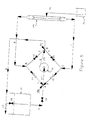
- Figure 2 which is a standard system (the prior art) operating in the reverse flow mode, (b), as compared to the system shown in Figure 1.
- the process fluid flows into the separation module through conduit 7 and exits the separation module through conduit 8.
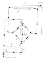
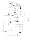
- FIG. 3 depicts the inventive concept of the present application.
- the process pump is placed within a valved conduit network, or loop, allowing the separation system to be operated in at least all the modes described above, (a) - (g), without any additional valves or pumps.
- the process fluid contained in tank T1 flows through valved conduit 5, past conduit junction A, and enters the inlet of pump P at P1.
- a conduit junction is defined as a point or place within a system where the flow conduits connect or converge, but not necessarily at a single point.
- the process fluid is then discharged from pump P at P2, flows past conduit junction B, through valved conduit 3, past conduit junction D, and through conduit 8 to the separation module.
- the process fluid flows through the process side of the module, returns to the conduit loop at conduit junction C through conduit 7 as concentrate, flows through valve V2, through conduit junction A, whereby it is mixed with process fluid from tank T1 and returns back to the inlet P1 of the pump P.
- a portion of the mixed concentrate/process stream may be bled off at conduit junction B, through valve V6 in conduit 9 and returned to the process tank T1.
- the stream in conduit 9 is at elevated pressure, PA.
- FIGS 3 and 4 demonstrate the normal and reverse flow modes of operation (a) and (b).
- the permeate from the module can flow via conduit 10 to a separate permeate tank, T2, or alternately where the module contains no outer shell or no conduit for the permeate, the permeate can flow to a tank in which the module is submerged (not shown).
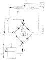
- Figure 5 depicts the system of this invention operating in the suction backwash mode with the backwash liquor exiting the process side flow channels simultaneously in the normal flow and reverse flow directions, (e). This is accomplished by opening valves V1, V2 and V7 and closing valves V3, V4, V5 and V6.
- the process pump P provides suction or negative pressure to the process side of the separation module by way of conduit 7 and 8, allowing filtrate to flow from tank T2, via conduit 10, through the membrane and into the process side of the separation module. From the process side of the separation module, the backwash liquor flows through conduit 7 (normal flow) and conduit 8 (reverse flow).
- the backwash liquor that flows through conduit 8 flows to conduit junction D, through conduit 1 to conduit junction A, into pump P via pump inlet P1, is discharged from pump P at pump outlet P2, to conduit junction B and is discharged from the system via conduit 9 and valve V7.
- the backwash liquor flowing through conduit 7 flows to conduit junction C, through conduit 2 to conduit junction A where it joins the backwash liquor from the reverse flow as described above.
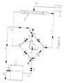
- FIG 6 depicts the system of this invention operating in the suction backwash mode with the backwash liquor exiting the process side flow channel in the normal flow direction, (f). This is accomplished by closing all the valves except valves V2 and V7.
- the backwash liquor flows from the process side of the separation module via conduit 7 to conduit junction C, via conduit 2 to conduit junction A, into pump P via pump inlet P1, is discharged from pump P at pump outlet P2, to conduit junction B and is discharged from the system via conduit 9.
- This process can be reversed and suction backwashing can take place in the reverse mode of operation, (g), as shown in Figure 7 whereby all valves are closed except valves V1 and V7.
- Figure 8 depicts a system of EP-A-0335647 in the normal mode of operation, (a).
- Two pumps of equal size are required for the system to be run, a process pump (Pl) and a permeate pump (P2).
- T1 represents a process tank
- T2 represents a permeate tank
- X represents the permeate outlet
- Y represents the process fluid return
- V1 to V9 represent valves
- F1 to F3 represent flow meters
- P1 refers to pressure indicators.
- the system of the present invention requires only a single process pump to operate both in the normal modes of operation and in the suction backwash mode, therefore, no cross-contamination takes place. Besides this advantage of no cross-contamination, the system of the present invention can be manufactured for a substantial reduction in cost and can operate with a substantial reduction in energy consumption as compared to the system of EP-A-0335647.
- a system according to the present invention equipped with two types of hollow fiber membrane cartridges (Romicon HF25-43-CM50 and HF25-43-XM50), was used to treat a metal plating waste containing suspended solids and zinc. Both types of membranes gave rejection coefficients in the 98% range over the course of a three day study. During this study a concentration factor of 1250X was achieved, that is, for every 4731.63 litres (1250 gallons) of feed (waste water), 4727.84 litres (1249 gallons) of filtrate were produced.
Landscapes
- Engineering & Computer Science (AREA)
- Water Supply & Treatment (AREA)
- Chemical & Material Sciences (AREA)
- Chemical Kinetics & Catalysis (AREA)
- Separation Using Semi-Permeable Membranes (AREA)
Abstract
Description
- The present invention is concerned with an improved separation system and its method of operation for the separation of solutes, colloidal particles, or suspended matter from solutions or suspensions containing the same. In a preferred embodiment, this invention is concerned with a simple and economic membrane filtration system that can be operated in many of the modes of operation of a membrane filtration system without mixing the filtrate with the feed stream.
- Separation techniques, such as reverse osmosis, ultrafiltration and microfiltration, are widely used today in industry. Many advantages have been realized by employing these techniques, among which are: the reduction in time required for effecting separation; efficiency in separation; the use of mild operating conditions such as room temperature separations; the reduction in operating costs as compared to older techniques such as evaporation, chemical precipitation, and ultracentrifugation; and the capability to separate species previously considered inseparable.
- The present invention is particularly concerned with membrane separations by ultrafiltration techniques, although it can be applied to other of the above-mentioned separation techniques.
- Ultrafiltration is a separation process wherein a solution or suspension, containing a solute, colloidal particle or suspended particle of greater dimensions than the solvent it is dissolved in, is fractionated by being subjected to such pressure as to force the solvent through a porous filter, particularly a polymeric membrane (see for example USA-3,615,024; US-A-3,526,588; US-A-3,556,305; US-A-3,541,005; and US-A-3,549,016; all of which are hereby incorporated herein by reference to be generally illustrative of the types of polymeric membranes contemplated), although the filter can be of the nonpolymeric type such as ceramic. The membranes used in ultrafiltration may be of various configurations such as hollow fiber, flat sheet, spiral wound or tubular. Preferably, for the purposes of the present invention, hollow fiber polymeric membranes are employed.
- Membrane separation systems are usually operated in a cross-flow mode whereby the process fluid flow (i.e. the "feed stream" to be separated) is tangential to the surface of the polymeric membrane. That is, the process fluid to be treated enters the separation module via the process fluid inlet, flows parallel to the surface of the membrane on the same side as the process fluid inlet and outlet are located, leaves the separation module via the process fluid outlet, and, optionally, is recycled back to the separation module for further treatment. A portion of the process fluid passes through the membrane as permeate. This type of separation module may be used for various purposes such as: to concentrate a fluid, in which case the desired product is the fluid leaving the separator through the process fluid outlet; to purify a fluid, in which case the desired product can be the permeate or the fluid leaving the separator through the process fluid outlet; or to separate one or more components from a fluid, in which case the desired product may be the fluid passing through the membrane as permeate, the fluid leaving the separator through the process fluid outlet, the component(s) retained by the membrane, or combination thereof.
- During use, the side of the membrane contacting the process fluid can become fouled by material retained by the membrane. Such fouled membranes can be cleaned for reuse by such techniques as: mechanical cleaning, for example, the removal of foulant material by using a brush, rod or sponge; fast-flush, i.e. the pumping of fluid across the fouled surface of the membrane at high flow rate to physically dislodge and remove the foulant; fast-flush with reverse flow, i.e. the pumping of fluid across the fouled surface of the membrane at high flow rate with periodic reversal of the flow direction to physically dislodge and remove the foulant; chemical cleaning, i.e. the contacting of the fouled surface of the membrane with a chemical cleaning fluid; pressure backwash, i.e. the pumping of fluid, for example permeate or water, under pressure through the membrane from the permeate side to the process fluid side such that the fluid physically dislodges and removes foulant material from the surface of the membrane; or a combination of two or more of the above-mentioned techniques.
- In the above-described techniques of fast-flush, chemical cleaning and pressure backwashing, pressure is usually created by means of a pump. This can give rise to hydraulic pressure surges that can damage the membrane. Therefore, it is important that the fluid pressure is carefully controlled so that the pressure difference between the fluid on one side of the membrane and that on the other side of the membrane does not exceed the maximum allowable transmembrane pressure difference for that particular membrane. The maximum allowable transmembrane pressure difference for a particular membrane is the maximum pressure difference between opposite sides of a membrane that can be accommodated by the membrane without damage resulting.
- Certain membrane configurations with narrow process fluid flow paths may become severely fouled, whereby the foulant restricts or even prevents the free flow of process fluid across the membrane surface. If this occurs, the fast-flush and chemical cleaning techniques may be insufficient to adequately clean the membrane, and mechanical cleaning and/or pressure backwashing may be required to achieve satisfactory cleaning. However, mechanical cleaning may be impractical for these membrane configurations because of their narrow process fluid flow paths, and pressure backwashing, as discussed above, has the disadvantages of having to carefully control the pressure of the fluid in order to avoid damage to the membranes, and of the addition of extra pumping capacity which adds to both the initial cost of the system and to the overall operating cost of the system.
- EP-A-0335647 and EP-A-0335648 describe a system, and a method of operating such a system, that enables the problem of hydraulic pressure surges, leading to damaged fibers, to be avoided. A suction backwash procedure is described in the above-mentioned patent applications to aid in the cleaning of the membranes. To activate the suction backwash procedure, a permeate pump is used to draw permeate through the hollow fibers by way of the process lines. While otherwise an improvement to the systems available heretofore, there are several problems and limitations to such a system design. Firstly, the system described in EP-A-0335647 is very complex, more costly than necessary, and requires at least two pumps of equal size, one process pump, and one permeate pump. This additional pumping capacity not only adds cost to the initial system construction, but also increases the energy requirement during operation. Secondly, because the process fluid comes into contact with the permeate pump and associated permeate lines, the permeate lines and permeate pump become contaminated with the process fluid. This limits the possible applications of such a system design. After use of the suction backwash procedure, and prior to operation in the standard fluid treatment mode, the system must be re-cleaned and/or re-sterilized.
- An essential part of many separation techniques, as in membrane filtration, is the ability to keep the filtrate separate from the feed and therefore avoid mixing the permeate with the process fluid. This is beneficial in applications where the filtrate stream must remain sanitary, such as in food or pharmaceutical applications, or where the feed stream can contaminate the filtrate, such as in waste applications.
- The present invention provides a novel, simple and economical separation system that reduces the equipment and/or energy requirements associated with such systems and is capable of operating in many of the modes of operation of a separation system, including suction backwash, while keeping the filtrate stream separate from the process stream.
- According to the present invention there is provided an apparatus for conducting separations comprising:
- (a) one or more separation modules, the or each separation module comprising inlet means for process fluid and outlet means for process fluid;
- (b) a plurality of conduit junctions connected together by a plurality of valved conduits to form a loop for introducing fluid under positive pressure in both forward and reverse flow directions to said separation module(s) and for providing negative pressure on the inlet and/or outlet side of said separation module(s);
- (c) pressure means comprising an inlet and an outlet, said inlet being connected to one of said conduit junctions and said outlet being connected to a second of said conduit junctions; and
- (d) means to take off permeate from said separation module(s).
- According to the present invention there is also provided a method of separating solutes, colloidal particles and/or suspended matter from a solution or suspension of such matter, which comprises:-
- (a) connecting a pump to a loop comprised of four conduit junctions A, B, C and D connected together by four valved conduits and junction A is connected to junctions D and C and is further connected to a valved inlet feed stream conduit and a conduit to the inlet of said pump, junction B is connected to junctions D and C and is further connected to a valved discharge conduit and by conduit to the outlet of said pump, junction D is connected to junctions A and B and is further connected by conduit to inlet means of one or more separation module on the process side, and junction C is connected to junctions A and B and is further connected to outlet means of said separation module(s) on the process side;
- (b) (i) pumping said solution or suspension into said valved conduit loop at conduit junction B, out of said valved conduit loop at conduit junction D, through said separation module(s) and back to said valved conduit loop at conduit junction C; and/or
(ii) reversing the flow by pumping said solution or suspension into said valved conduit loop at conduit junction B, out of said valved conduit loop at conduit junction c, through said separation module(s) and back to said valved conduit loop at conduit junction D; - (c) recovering concentrate containing solutes, colloidal particles or suspended matter; and
- (d) withdrawing permeate from said separation module(s).
- As used herein, the term "positive pressure" refers to an increased pressure which is above the overall pressure in the apparatus, and the term "negative pressure" refers to a decreased pressure which is below the overall pressure in the apparatus. In a preferred embodiment of the invention, the positive pressure is above atmospheric pressure, and the negative pressure is below atmospheric pressure.
- The membrane separation system of the invention can operate in many of the standard modes of operating a membrane separation system such as: (a) normal flow of the process side fluid during filtration; (b) reverse flow of the process side fluid during filtration; (c) normal flow of the process side fluid during filtration with filtrate recycle, the isolation and return of the filtrate to the process side; (d) reverse flow of the process side fluid during filtration with filtrate recycle; (e) suction backwash with the backwash liquor exiting the process side flow channels simultaneously in the normal flow and reverse flow directions; (f) suction backwash with the backwash liquor exiting the process side flow channel in the normal flow direction; and (g) suction backwash with the backwash liquor exiting the process side flow channel in the reverse flow direction. Furthermore, this invention allows for the economical operation in many of the operating modes, especially in the suction backwash mode, without requiring the suction backwash fluid to contact and contaminate the filtrate fluid with process fluid debris.
- The process side of the membrane module is the side where the process fluid comes into contact with the membrane surface. The process fluid is carried to the process side of the membrane module by way of the process fluid conduit. Upon leaving the membrane module the process fluid has lost a portion of its solvent as permeate, and therefore as the process fluid leaves the membrane module it is more concentrated in the components of larger size than the pores of the membrane. As used herein, the term "permeate" refers to the stream passing through the membrane surface and the term "concentrate" defines the portion of the stream exiting the membrane module on the process side containing the retained, non-permeating species. The concentrate is carried away from the module in the concentrate fluid conduit.
- A separation module, as discussed herein, includes conventional membrane cartridges such as containers housing membranes within a solid outer wall having one or more permeate outlets. The solid outer wall is so spaced from the membranes as to enable the permeate to collect and surround the membrane. The cartridges can be connected with a process fluid inlet, concentrate outlet, and a conduit for discharge of the permeate or if no conduit for the permeate is used, the permeate can flow into a tank surrounding the cartridge. A single cartridge can be used or multiple cartridges can be connected to a manifold to allow for the cartridges to be run in series and/or parallel configuration. Alternately, the solid outer wall of the cartridge described above can be eliminated, the cartridges suspended in a tank, and the permeate allowed to flow into said tank which surrounds the membrane module or modules. The permeate is then subsequently carried off.
The present invention will now be further described with reference to the accompanying drawings, in which:- - FIG. 1 is a schematic representation of a currently available system, (the prior art), operating in the normal flow mode;
- FIG. 2 is a schematic representation of a currently available system, (the prior art), operating in the reverse flow mode;
- FIG. 3 is a schematic representation of a separation system according to the present invention operating in the normal flow mode;
- FIG. 4 is a schematic representation of a separation system according to the present invention operating in the reverse flow mode;
- FIG. 5 is a schematic representation of a separation system according to the present invention operating in the suction backwash mode with the backwash liquor exiting the process side flow channels simultaneously in the normal flow and reverse flow directions;
- FIG. 6 is a schematic representation of a separation system according to the present invention operating in the suction backwash mode with the backwash liquor exiting the process side flow channel in the normal flow mode;
- FIG. 7 is a schematic representation of a separation system according to the present invention operating in the suction backwash mode with the backwash liquor exiting the process side flow channel in the reverse flow mode;
- FIG. 8 is a schematic representation of a separation system according to copending EP-A-0335647 operating in the normal flow mode;
- FIG. 9 is a schematic representation of a separation system of copending EP-A-0335647 operating in the suction backwash mode with the backwash liquor exiting the process side flow channels simultaneously in the normal flow and reverse flow directions;
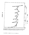
- FIG. 10 is a graph of the flux rate generated during operation of a system according to the present invention versus the running time; and
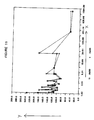
- FIG. 11 is a graph of the flux rate generated during operation of a system according to the present invention versus concentration factor.
- In Figures 1 to 7 like references denote like parts, and in Figures 8 and 9 like references denote like parts.
- Referring to Figure 3, the illustrated membrane separation system according to the present invention places the process pump P, having an inlet P1 and an outlet P2, within a network of valved conduits comprising a conduit loop connected in such a manner as to allow the use of at least all the operating modes described above, including suction backwash, while keeping the filtrate stream completely separate from the feed stream. This process can best be described by the figures, and by comparing the system of this invention to standard membrane filtration systems.
- Figure 1 is a simplified schematic representation of a currently available system (the prior art) operating in the normal flow mode, (a). The process fluid flows from process tank T1, through
valved conduit 5, through pump P, having inlet P1 and outlet P2, and into a valve network containing four valves, V1 to V4. Valves V1 and V4 are open and valves V2 and V3 closed. The process stream then flows through valved conduit 1, throughconduit 8, and to the inlet of the separation module (sm). The process fluid passes through the separation module, throughconduit 7 as concentrate, reenters the valve network, flows through valve V₄ and exits throughconduit 9. The concentrate can exit the system viaconduit 9 through valve V7 (shown closed), return to the process tank T1 through valve V6, or a combination of both. The pressure at the pump discharge and the inlet to the valve network is designated PA, while the pressure at the outlet of the valve network is designated PB. Also, the stream exiting throughconduit 9 is at lower pressure, PB. In all cases of standard operation, PA is greater than PB. The rate of flow through the separation module is determined by the pressure difference across the separation module which is determined by valves V1 and V4. Filtrate produced in the separation module exits throughconduit 10. - The direction of the flow shown in Figure i can be reversed by closing valves V1 and V4 and opening valves V2 and V3. This is shown in Figure 2 which is a standard system (the prior art) operating in the reverse flow mode, (b), as compared to the system shown in Figure 1. In Figure 2 the process fluid flows into the separation module through
conduit 7 and exits the separation module throughconduit 8. - The simplified schematic drawing shown in Figure 3 depicts the inventive concept of the present application. The process pump is placed within a valved conduit network, or loop, allowing the separation system to be operated in at least all the modes described above, (a) - (g), without any additional valves or pumps. In Figure 3, the process fluid contained in tank T1, flows through
valved conduit 5, past conduit junction A, and enters the inlet of pump P at P1. As used herein, a conduit junction is defined as a point or place within a system where the flow conduits connect or converge, but not necessarily at a single point. The process fluid is then discharged from pump P at P2, flows past conduit junction B, throughvalved conduit 3, past conduit junction D, and throughconduit 8 to the separation module. The process fluid flows through the process side of the module, returns to the conduit loop at conduit junction C throughconduit 7 as concentrate, flows through valve V2, through conduit junction A, whereby it is mixed with process fluid from tank T1 and returns back to the inlet P1 of the pump P. A portion of the mixed concentrate/process stream may be bled off at conduit junction B, through valve V6 inconduit 9 and returned to the process tank T1. The stream inconduit 9 is at elevated pressure, PA. - Flow reversal is achieved by opening valves V1 and V4 and closing valves V2 and V3. This is depicted in Figure 4. The process fluid flow is identical to that shown in Figure 3 up to conduit junction B. In the reverse flow mode the process fluid flows from conduit junction B to conduit junction C via
valved conduit 4. It then flows throughconduit 7 to the separation module. The process fluid flows through the process side of the module, returns to the conduit loop at conduit junction D throughconduit 8 as concentrate, flows through valve V1 and through conduit junction A. The remainder of the process is now identical to normal flow. - Figures 3 and 4 demonstrate the normal and reverse flow modes of operation (a) and (b). As shown in these figures, the permeate from the module can flow via
conduit 10 to a separate permeate tank, T2, or alternately where the module contains no outer shell or no conduit for the permeate, the permeate can flow to a tank in which the module is submerged (not shown). - The modes of operation described in Figures 3 and 4 are similar to those described using the conventional systems of Figures 1 and 2. However, in the system of this invention the process stream exits the valve network at higher pressure, PA, than in the conventional systems, where the process stream exits the valve network at lower pressure PB. This has the advantage of enabling the concentrated process stream to return to a distant feed tank or reservoir for further concentration or to be passed through a filter, such as a bag or cartridge type filter, to remove debris from the stream, and debris removed from the membrane during cleaning.
- Figure 5 depicts the system of this invention operating in the suction backwash mode with the backwash liquor exiting the process side flow channels simultaneously in the normal flow and reverse flow directions, (e). This is accomplished by opening valves V1, V2 and V7 and closing valves V3, V4, V5 and V6. The process pump P provides suction or negative pressure to the process side of the separation module by way of
conduit conduit 10, through the membrane and into the process side of the separation module. From the process side of the separation module, the backwash liquor flows through conduit 7 (normal flow) and conduit 8 (reverse flow). The backwash liquor that flows throughconduit 8 flows to conduit junction D, through conduit 1 to conduit junction A, into pump P via pump inlet P1, is discharged from pump P at pump outlet P2, to conduit junction B and is discharged from the system viaconduit 9 and valve V7. The backwash liquor flowing throughconduit 7 flows to conduit junction C, throughconduit 2 to conduit junction A where it joins the backwash liquor from the reverse flow as described above. When the backwash fluid exits the cartridge, it is constrained to the process side piping network. Therefore, foulant, plugs, and debris do not interfere or contaminate filtrate lines. - Figure 6 depicts the system of this invention operating in the suction backwash mode with the backwash liquor exiting the process side flow channel in the normal flow direction, (f). This is accomplished by closing all the valves except valves V2 and V7. The backwash liquor flows from the process side of the separation module via
conduit 7 to conduit junction C, viaconduit 2 to conduit junction A, into pump P via pump inlet P1, is discharged from pump P at pump outlet P2, to conduit junction B and is discharged from the system viaconduit 9. This process can be reversed and suction backwashing can take place in the reverse mode of operation, (g), as shown in Figure 7 whereby all valves are closed except valves V1 and V7. - For further comparison, Figure 8 depicts a system of EP-A-0335647 in the normal mode of operation, (a). Two pumps of equal size are required for the system to be run, a process pump (Pl) and a permeate pump (P2). In Figure 8, T1 represents a process tank, T2 represents a permeate tank, X represents the permeate outlet, Y represents the process fluid return, V1 to V9 represent valves, F1 to F3 represent flow meters, and P1 refers to pressure indicators. When suction backwash is used in the system as shown in Figure 9, the permeate pump provides the suction or negative pressure on the fibers, draws permeate from the container the cartridges are submerged in, and the permeate passes through the fibers. All foulants, plugs and contaminants contained in the fibers and on the membrane surface are now exposed to the permeate pump and associated permeate lines, causing said lines to become contaminated with process fluid and foulants. As stated above, in applications such as pharmaceutical, dairy, or waste, this would necessitate the re-sterilization or recleaning of the permeate lines and permeate pump.
- As described above, the system of the present invention requires only a single process pump to operate both in the normal modes of operation and in the suction backwash mode, therefore, no cross-contamination takes place. Besides this advantage of no cross-contamination, the system of the present invention can be manufactured for a substantial reduction in cost and can operate with a substantial reduction in energy consumption as compared to the system of EP-A-0335647.
- The present invention will now be further illustrated by way of the following Examples which are for illustrative purposes only and are not to be construed as imposing any limitation on the scope of the invention.
- The cost and power requirements of a system according to the present invention were compared to the cost and power requirements of a system according to EP-A-0335647. The data for the system of the present invention are presented in Table 1 below as percentages of the cost and power requirements of a system according to EP-A-0335647 and as illustrated in Figure 8 of the accompanying drawings. Each system was designed to produce 75.71 litres (20 gallons) a minute of high quality filtered water from a specific city water feed by using 18.58 sq meters (200 sq. ft.) of an 80,000 molecular weight cutoff membrane.
TABLE 1 Item Cost Reduction piping and tanks 63% pumping 61.5% total capital costs 63% power required 55% - A system according to the present invention, equipped with two types of hollow fiber membrane cartridges (Romicon HF25-43-CM50 and HF25-43-XM50), was used to treat a metal plating waste containing suspended solids and zinc. Both types of membranes gave rejection coefficients in the 98% range over the course of a three day study. During this study a concentration factor of 1250X was achieved, that is, for every 4731.63 litres (1250 gallons) of feed (waste water), 4727.84 litres (1249 gallons) of filtrate were produced.
- The analytical data collected during this study are shown in Table 2.
TABLE 2 SAMPLE Suspended Solids ppm Zinc ppm feed A 686 3.2 feed B 1,286 179 CM permeate A 18.4 0.07 CM permeate B 13.2 0.05 CM rejection coefficient 98.2% 98.9% XM permeate A 25.0 0.16 XM permeate B 13.2 0.08 XM rejection coefficient 97.8% 97.5% - In Figures 10 and 11 of the accompanying drawings the filtration rate in the form of fluxes (gallons filtrate/area/time, gallons/sq. ft./day) (axis "Y" in Figures 10 and 11) is shown as a function of time in Figure 10 (time is given in hours and is axis "X" in Figure 10) and as a function of concentration factor in Figure 11 (axis "X" in Figure 11). The "saw tooth" pattern in both figures is the result of the suction backwash operation, demonstrating how the membranes were sufficiently cleaned during processing to restore the filtrate rate close to its initial value without the need for a shutdown or an external cleaning step.
Claims (12)
(ii) reversing the flow by pumping said solution or suspension into said valved conduit loop at conduit junction B, out of said valved conduit loop at conduit junction C, through said separation module(s) and back to said valved conduit loop at conduit junction D;
(e) cleaning said separation module(s) by applying negative pressure to the process side of said separation module(s) and thereby drawing filtrate from the filtrate side of said separation module(s) into the process side of said module(s), into said valved conduit loop at conduit junction D, conduit junction C or a combination thereof, through valved conduit junction A, into said pump and out of said valved conduit loop at conduit junction B.
Applications Claiming Priority (2)
| Application Number | Priority Date | Filing Date | Title |
|---|---|---|---|
| US433888 | 1989-11-08 | ||
| US07/433,888 US4986918A (en) | 1989-11-08 | 1989-11-08 | Membrane separation system and method of operation |
Publications (2)
| Publication Number | Publication Date |
|---|---|
| EP0427376A2 true EP0427376A2 (en) | 1991-05-15 |
| EP0427376A3 EP0427376A3 (en) | 1992-09-02 |
Family
ID=23721941
Family Applications (1)
| Application Number | Title | Priority Date | Filing Date |
|---|---|---|---|
| EP19900308157 Ceased EP0427376A3 (en) | 1989-11-08 | 1990-07-25 | Membrane separation system and method of operation |
Country Status (20)
| Country | Link |
|---|---|
| US (1) | US4986918A (en) |
| EP (1) | EP0427376A3 (en) |
| JP (1) | JPH03154620A (en) |
| KR (1) | KR910009327A (en) |
| CN (1) | CN1051519A (en) |
| AU (1) | AU634259B2 (en) |
| BR (1) | BR9003537A (en) |
| CA (1) | CA2020631A1 (en) |
| DD (1) | DD296621A5 (en) |
| FI (1) | FI903719A0 (en) |
| HU (1) | HUT58557A (en) |
| IE (1) | IE902678A1 (en) |
| IL (1) | IL95173A0 (en) |
| MX (1) | MX164298B (en) |
| NO (1) | NO903282L (en) |
| NZ (1) | NZ234632A (en) |
| PH (1) | PH26937A (en) |
| PL (1) | PL286278A1 (en) |
| PT (1) | PT94894A (en) |
| ZA (1) | ZA905881B (en) |
Cited By (9)
| Publication number | Priority date | Publication date | Assignee | Title |
|---|---|---|---|---|
| EP0479492A1 (en) * | 1990-10-04 | 1992-04-08 | Koch Membrane Systems, Inc | Membrane separation system and methods of operating and cleaning such a system |
| WO2001051186A1 (en) * | 2000-01-13 | 2001-07-19 | Bucher-Guyer Ag | Method and device for clearing flow paths in filtration modules |
| US6692786B1 (en) | 1994-01-19 | 2004-02-17 | Wissenschaftsforderung Der Deutschen Brauwirtschaft E.V. | Beer clarification process by crossflow microfiltration |
| US7025885B2 (en) | 1998-11-23 | 2006-04-11 | Zenon Environmental Inc. | Water filtration using immersed membranes |
| US7063788B2 (en) | 1995-08-11 | 2006-06-20 | Zenon Environmental Inc. | Apparatus for withdrawing permeate using an immersed vertical skein of hollow fibre membranes |
| US7087173B2 (en) | 1995-08-11 | 2006-08-08 | Zenon Environmental Inc. | Inverted cavity aerator for membrane module |
| US7537701B2 (en) | 1995-08-11 | 2009-05-26 | Zenon Technology Partnership | Membrane filtration module with adjustable header spacing |
| USRE42669E1 (en) | 1995-08-11 | 2011-09-06 | Zenon Technology Partnership | Vertical cylindrical skein of hollow fiber membranes and method of maintaining clean fiber surfaces |
| US8852438B2 (en) | 1995-08-11 | 2014-10-07 | Zenon Technology Partnership | Membrane filtration module with adjustable header spacing |
Families Citing this family (20)
| Publication number | Priority date | Publication date | Assignee | Title |
|---|---|---|---|---|
| US5171767A (en) * | 1991-05-06 | 1992-12-15 | Rohm And Haas Company | Utrafiltration process for the recovery of polymeric latices from whitewater |
| US5207917A (en) * | 1991-10-08 | 1993-05-04 | Weaver Thomas J M | Recycling and recovery of aqueous cleaner solutions |
| DE4203157A1 (en) * | 1992-02-05 | 1993-08-12 | Henkel Kgaa | METHOD FOR CLEANING GLYCERINE WATER |
| DE4218115A1 (en) * | 1992-06-02 | 1993-12-09 | Guenter Lauer | Process and treatment device for pure water production |
| US5403489A (en) * | 1993-06-24 | 1995-04-04 | Minnesota Mining And Manufacturing Company | Solid phase extraction method and apparatus |
| US6359114B1 (en) * | 1995-06-07 | 2002-03-19 | Aphton Corp. | System for method for the modification and purification of proteins |
| US5958243A (en) * | 1996-07-11 | 1999-09-28 | Zenon Environmental Inc. | Apparatus and method for membrane filtration with enhanced net flux |
| US6755970B1 (en) * | 1999-06-22 | 2004-06-29 | Trisep Corporation | Back-flushable spiral wound filter and methods of making and using same |
| US6613233B1 (en) | 2000-08-23 | 2003-09-02 | Univ Illinois | Multiple mode industrial process system and method |
| CN1571827A (en) * | 2001-10-18 | 2005-01-26 | 国际壳牌研究有限公司 | Continuous process to separate colour bodies and/or asphalthenic contaminants from a hydrocarbon mixture |
| EP1463578B1 (en) * | 2002-01-09 | 2011-09-28 | Hydranautics | Method for cleaning a filtration membrane module with hollow fiber membranes |
| US20060180548A1 (en) * | 2005-02-17 | 2006-08-17 | Zhenghua Ji | Liquid depletion in solid phase separation processes |
| JP4941393B2 (en) * | 2008-04-14 | 2012-05-30 | トヨタ紡織株式会社 | Dilute fuel treatment system for internal combustion engine |
| CA2734485A1 (en) * | 2008-08-18 | 2010-02-25 | Siemens Water Technologies Corp. | Method and system for biofouling control of shipboard components |
| US8916156B2 (en) | 2010-07-02 | 2014-12-23 | Rembrandt Enterprises, Inc. | Isolated egg protein and egg lipid materials, and methods for producing the same |
| US8642038B2 (en) | 2010-07-02 | 2014-02-04 | Rembrandt Enterprises, Inc. | Isolated egg protein and egg lipid materials, and methods for producing the same |
| GB2502089A (en) * | 2012-05-15 | 2013-11-20 | Pell Frischmann Consultants Ltd | Filtering contaminants from fluid |
| US9550152B2 (en) | 2013-03-07 | 2017-01-24 | Pentair Residential Filtration, Llc | Point of use filtration system with backwash |
| US10864481B1 (en) * | 2018-08-20 | 2020-12-15 | Dileep Kumar Agnihotri | Energy efficient low-fouling high-recovery reverse osmosis system for brackish water desalination |
| WO2024081574A1 (en) * | 2022-10-10 | 2024-04-18 | Repligen Corporation | Filtration systems and methods |
Citations (4)
| Publication number | Priority date | Publication date | Assignee | Title |
|---|---|---|---|---|
| DE1949059A1 (en) * | 1969-09-29 | 1971-04-01 | Mull Werner Dr Ing | Filter for liquids and gases |
| US3992301A (en) * | 1973-11-19 | 1976-11-16 | Raypak, Inc. | Automatic flushing system for membrane separation machines such as reverse osmosis machines |
| EP0335648A2 (en) * | 1988-03-31 | 1989-10-04 | Koch Membrane Systems, Inc | Method of operating membrane separation systems |
| WO1989011899A1 (en) * | 1988-06-08 | 1989-12-14 | Invitron Corporation | Tandem hollow fiber cell culture product harvest system |
Family Cites Families (5)
| Publication number | Priority date | Publication date | Assignee | Title |
|---|---|---|---|---|
| US3352658A (en) * | 1964-04-13 | 1967-11-14 | Corning Glass Works | Method of forming charges of molten glass |
| NL134681C (en) * | 1966-04-26 | |||
| US3556305A (en) * | 1968-03-28 | 1971-01-19 | Amicon Corp | Composite membrane and process for making same |
| US3615024A (en) * | 1968-08-26 | 1971-10-26 | Amicon Corp | High flow membrane |
| US3541005A (en) * | 1969-02-05 | 1970-11-17 | Amicon Corp | Continuous ultrafiltration of macromolecular solutions |
-
1989
- 1989-11-08 US US07/433,888 patent/US4986918A/en not_active Expired - Fee Related
-
1990
- 1990-07-06 CA CA002020631A patent/CA2020631A1/en not_active Abandoned
- 1990-07-06 PH PH40798A patent/PH26937A/en unknown
- 1990-07-20 BR BR909003537A patent/BR9003537A/en unknown
- 1990-07-23 IE IE267890A patent/IE902678A1/en unknown
- 1990-07-24 NZ NZ234632A patent/NZ234632A/en unknown
- 1990-07-24 NO NO90903282A patent/NO903282L/en unknown
- 1990-07-24 IL IL95173A patent/IL95173A0/en unknown
- 1990-07-24 FI FI903719A patent/FI903719A0/en not_active Application Discontinuation
- 1990-07-24 HU HU904592A patent/HUT58557A/en unknown
- 1990-07-25 EP EP19900308157 patent/EP0427376A3/en not_active Ceased
- 1990-07-25 AU AU59824/90A patent/AU634259B2/en not_active Withdrawn - After Issue
- 1990-07-26 DD DD90343097A patent/DD296621A5/en not_active IP Right Cessation
- 1990-07-26 ZA ZA905881A patent/ZA905881B/en unknown
- 1990-07-31 PL PL28627890A patent/PL286278A1/en unknown
- 1990-08-01 JP JP2204960A patent/JPH03154620A/en active Pending
- 1990-08-02 PT PT94894A patent/PT94894A/en not_active Application Discontinuation
- 1990-08-10 CN CN90106902A patent/CN1051519A/en active Pending
- 1990-11-06 MX MX23208A patent/MX164298B/en unknown
- 1990-11-06 KR KR1019900017879A patent/KR910009327A/en not_active Application Discontinuation
Patent Citations (5)
| Publication number | Priority date | Publication date | Assignee | Title |
|---|---|---|---|---|
| DE1949059A1 (en) * | 1969-09-29 | 1971-04-01 | Mull Werner Dr Ing | Filter for liquids and gases |
| US3992301A (en) * | 1973-11-19 | 1976-11-16 | Raypak, Inc. | Automatic flushing system for membrane separation machines such as reverse osmosis machines |
| EP0335648A2 (en) * | 1988-03-31 | 1989-10-04 | Koch Membrane Systems, Inc | Method of operating membrane separation systems |
| EP0335647A2 (en) * | 1988-03-31 | 1989-10-04 | Koch Membrane Systems, Inc | Multiple membrane separation systems |
| WO1989011899A1 (en) * | 1988-06-08 | 1989-12-14 | Invitron Corporation | Tandem hollow fiber cell culture product harvest system |
Cited By (13)
| Publication number | Priority date | Publication date | Assignee | Title |
|---|---|---|---|---|
| EP0479492A1 (en) * | 1990-10-04 | 1992-04-08 | Koch Membrane Systems, Inc | Membrane separation system and methods of operating and cleaning such a system |
| US6692786B1 (en) | 1994-01-19 | 2004-02-17 | Wissenschaftsforderung Der Deutschen Brauwirtschaft E.V. | Beer clarification process by crossflow microfiltration |
| US7708888B2 (en) | 1995-08-11 | 2010-05-04 | Zenon Technology Partnership | Apparatus for withdrawing permeate using an immersed vertical skein of hollow fibre membranes |
| US7063788B2 (en) | 1995-08-11 | 2006-06-20 | Zenon Environmental Inc. | Apparatus for withdrawing permeate using an immersed vertical skein of hollow fibre membranes |
| US7087173B2 (en) | 1995-08-11 | 2006-08-08 | Zenon Environmental Inc. | Inverted cavity aerator for membrane module |
| US7534353B2 (en) | 1995-08-11 | 2009-05-19 | Zenon Technology Partnership | Apparatus for withdrawing permeate using an immersed vertical skein of hollow fibre membranes |
| US7537701B2 (en) | 1995-08-11 | 2009-05-26 | Zenon Technology Partnership | Membrane filtration module with adjustable header spacing |
| US7615157B2 (en) | 1995-08-11 | 2009-11-10 | Zenon Technology Partnership | Apparatus for withdrawing permeate using an immersed vertical skein of hollow fibre membranes |
| USRE42669E1 (en) | 1995-08-11 | 2011-09-06 | Zenon Technology Partnership | Vertical cylindrical skein of hollow fiber membranes and method of maintaining clean fiber surfaces |
| US8075776B2 (en) | 1995-08-11 | 2011-12-13 | Zenon Technology Partnership | Apparatus for withdrawing permeate using an immersed vertical skein of hollow fibre membranes |
| US8852438B2 (en) | 1995-08-11 | 2014-10-07 | Zenon Technology Partnership | Membrane filtration module with adjustable header spacing |
| US7025885B2 (en) | 1998-11-23 | 2006-04-11 | Zenon Environmental Inc. | Water filtration using immersed membranes |
| WO2001051186A1 (en) * | 2000-01-13 | 2001-07-19 | Bucher-Guyer Ag | Method and device for clearing flow paths in filtration modules |
Also Published As
| Publication number | Publication date |
|---|---|
| NO903282D0 (en) | 1990-07-24 |
| AU634259B2 (en) | 1993-02-18 |
| DD296621A5 (en) | 1991-12-12 |
| FI903719A0 (en) | 1990-07-24 |
| ZA905881B (en) | 1991-07-31 |
| JPH03154620A (en) | 1991-07-02 |
| CA2020631A1 (en) | 1991-05-09 |
| BR9003537A (en) | 1991-08-27 |
| IE902678A1 (en) | 1991-05-08 |
| IL95173A0 (en) | 1991-06-10 |
| NZ234632A (en) | 1992-02-25 |
| NO903282L (en) | 1991-05-10 |
| PH26937A (en) | 1992-12-03 |
| PL286278A1 (en) | 1991-05-20 |
| KR910009327A (en) | 1991-06-28 |
| HUT58557A (en) | 1992-03-30 |
| AU5982490A (en) | 1991-05-16 |
| IE902678L (en) | 1990-07-08 |
| MX164298B (en) | 1992-07-30 |
| HU904592D0 (en) | 1990-12-28 |
| EP0427376A3 (en) | 1992-09-02 |
| US4986918A (en) | 1991-01-22 |
| CN1051519A (en) | 1991-05-22 |
| PT94894A (en) | 1992-03-31 |
Similar Documents
| Publication | Publication Date | Title |
|---|---|---|
| US4986918A (en) | Membrane separation system and method of operation | |
| US5132015A (en) | Flow control for ultra filtration systems | |
| EP0966319B1 (en) | Portable reverse osmosis unit for producing drinking water | |
| Strathmann | Membrane separation processes | |
| EP0335648B1 (en) | Method of operating membrane separation systems | |
| US5409613A (en) | Recycling and recovery of aqueous cleaner solutions and treatment of associated rinse water | |
| US8795527B2 (en) | Filtration system | |
| Aptel et al. | Categories of membrane operations | |
| EP1726353A1 (en) | Membrane filtration of a product | |
| WO1997047375A1 (en) | Membrane filter system and pressure vessel suitable for membrane filtration | |
| US7422690B2 (en) | Filtering system | |
| ZA200404664B (en) | Membrane filter housing and method of using the same | |
| WO2017136626A1 (en) | Unhoused filtration device and methods of use | |
| WO2005081627A2 (en) | Crossflow filtration system and method for membrane fouling prevention | |
| EP0121785A2 (en) | Method and apparatus for enhancing the flux rate of cross-flow filtration systems | |
| JPH07185210A (en) | Filtration device | |
| JP3223568B2 (en) | Water treatment equipment | |
| JPH08290164A (en) | Water treating device | |
| JPS60212286A (en) | Treatment of rice washing water |
Legal Events
| Date | Code | Title | Description |
|---|---|---|---|
| PUAI | Public reference made under article 153(3) epc to a published international application that has entered the european phase |
Free format text: ORIGINAL CODE: 0009012 |
|
| 17P | Request for examination filed |
Effective date: 19900813 |
|
| AK | Designated contracting states |
Kind code of ref document: A2 Designated state(s): AT BE CH DE DK ES FR GB GR IT LI LU NL SE |
|
| PUAL | Search report despatched |
Free format text: ORIGINAL CODE: 0009013 |
|
| AK | Designated contracting states |
Kind code of ref document: A3 Designated state(s): AT BE CH DE DK ES FR GB GR IT LI LU NL SE |
|
| RAP1 | Party data changed (applicant data changed or rights of an application transferred) |
Owner name: KOCH MEMBRANE SYSTEMS, INC |
|
| 17Q | First examination report despatched |
Effective date: 19930727 |
|
| STAA | Information on the status of an ep patent application or granted ep patent |
Free format text: STATUS: THE APPLICATION HAS BEEN REFUSED |
|
| 18R | Application refused |
Effective date: 19950326 |