EP0427108A2 - Picture coding apparatus - Google Patents
Picture coding apparatus Download PDFInfo
- Publication number
- EP0427108A2 EP0427108A2 EP90120901A EP90120901A EP0427108A2 EP 0427108 A2 EP0427108 A2 EP 0427108A2 EP 90120901 A EP90120901 A EP 90120901A EP 90120901 A EP90120901 A EP 90120901A EP 0427108 A2 EP0427108 A2 EP 0427108A2
- Authority
- EP
- European Patent Office
- Prior art keywords
- coding
- quantization characteristics
- quantization
- outputting
- processing unit
- Prior art date
- Legal status (The legal status is an assumption and is not a legal conclusion. Google has not performed a legal analysis and makes no representation as to the accuracy of the status listed.)
- Granted
Links
- 238000013139 quantization Methods 0.000 claims abstract description 88
- 230000005540 biological transmission Effects 0.000 claims abstract description 13
- 238000004364 calculation method Methods 0.000 claims description 13
- 238000010606 normalization Methods 0.000 claims description 10
- 238000010586 diagram Methods 0.000 description 8
- 230000006866 deterioration Effects 0.000 description 3
- 230000003247 decreasing effect Effects 0.000 description 2
- 230000000694 effects Effects 0.000 description 2
- 230000003044 adaptive effect Effects 0.000 description 1
- 230000000903 blocking effect Effects 0.000 description 1
- 238000004891 communication Methods 0.000 description 1
- 230000003111 delayed effect Effects 0.000 description 1
- 238000002474 experimental method Methods 0.000 description 1
- 238000000034 method Methods 0.000 description 1
- 230000002123 temporal effect Effects 0.000 description 1
Images


Classifications
-
- H—ELECTRICITY
- H04—ELECTRIC COMMUNICATION TECHNIQUE
- H04N—PICTORIAL COMMUNICATION, e.g. TELEVISION
- H04N19/00—Methods or arrangements for coding, decoding, compressing or decompressing digital video signals
- H04N19/50—Methods or arrangements for coding, decoding, compressing or decompressing digital video signals using predictive coding
- H04N19/59—Methods or arrangements for coding, decoding, compressing or decompressing digital video signals using predictive coding involving spatial sub-sampling or interpolation, e.g. alteration of picture size or resolution
-
- H—ELECTRICITY
- H04—ELECTRIC COMMUNICATION TECHNIQUE
- H04N—PICTORIAL COMMUNICATION, e.g. TELEVISION
- H04N19/00—Methods or arrangements for coding, decoding, compressing or decompressing digital video signals
- H04N19/10—Methods or arrangements for coding, decoding, compressing or decompressing digital video signals using adaptive coding
- H04N19/102—Methods or arrangements for coding, decoding, compressing or decompressing digital video signals using adaptive coding characterised by the element, parameter or selection affected or controlled by the adaptive coding
- H04N19/124—Quantisation
-
- H—ELECTRICITY
- H04—ELECTRIC COMMUNICATION TECHNIQUE
- H04N—PICTORIAL COMMUNICATION, e.g. TELEVISION
- H04N19/00—Methods or arrangements for coding, decoding, compressing or decompressing digital video signals
- H04N19/10—Methods or arrangements for coding, decoding, compressing or decompressing digital video signals using adaptive coding
- H04N19/102—Methods or arrangements for coding, decoding, compressing or decompressing digital video signals using adaptive coding characterised by the element, parameter or selection affected or controlled by the adaptive coding
- H04N19/132—Sampling, masking or truncation of coding units, e.g. adaptive resampling, frame skipping, frame interpolation or high-frequency transform coefficient masking
-
- H—ELECTRICITY
- H04—ELECTRIC COMMUNICATION TECHNIQUE
- H04N—PICTORIAL COMMUNICATION, e.g. TELEVISION
- H04N19/00—Methods or arrangements for coding, decoding, compressing or decompressing digital video signals
- H04N19/10—Methods or arrangements for coding, decoding, compressing or decompressing digital video signals using adaptive coding
- H04N19/134—Methods or arrangements for coding, decoding, compressing or decompressing digital video signals using adaptive coding characterised by the element, parameter or criterion affecting or controlling the adaptive coding
- H04N19/146—Data rate or code amount at the encoder output
- H04N19/152—Data rate or code amount at the encoder output by measuring the fullness of the transmission buffer
-
- H—ELECTRICITY
- H04—ELECTRIC COMMUNICATION TECHNIQUE
- H04N—PICTORIAL COMMUNICATION, e.g. TELEVISION
- H04N19/00—Methods or arrangements for coding, decoding, compressing or decompressing digital video signals
- H04N19/50—Methods or arrangements for coding, decoding, compressing or decompressing digital video signals using predictive coding
- H04N19/503—Methods or arrangements for coding, decoding, compressing or decompressing digital video signals using predictive coding involving temporal prediction
-
- H—ELECTRICITY
- H04—ELECTRIC COMMUNICATION TECHNIQUE
- H04N—PICTORIAL COMMUNICATION, e.g. TELEVISION
- H04N19/00—Methods or arrangements for coding, decoding, compressing or decompressing digital video signals
- H04N19/50—Methods or arrangements for coding, decoding, compressing or decompressing digital video signals using predictive coding
- H04N19/587—Methods or arrangements for coding, decoding, compressing or decompressing digital video signals using predictive coding involving temporal sub-sampling or interpolation, e.g. decimation or subsequent interpolation of pictures in a video sequence
-
- H—ELECTRICITY
- H04—ELECTRIC COMMUNICATION TECHNIQUE
- H04N—PICTORIAL COMMUNICATION, e.g. TELEVISION
- H04N19/00—Methods or arrangements for coding, decoding, compressing or decompressing digital video signals
- H04N19/50—Methods or arrangements for coding, decoding, compressing or decompressing digital video signals using predictive coding
Definitions
- the present invention relates to a picture coding apparatus which is intended for high efficiency coding of digital video signals.
- FIG. 1 is a block diagram showing constitution of a picture coding apparatus in the prior art operating at a definite transmission rate, such as disclosed in Murakami, Asai et al. "Adaptive Type Vector Quantization System Interframe Coding" in Technical Report IE84-1 of the Institute of Electronic and Communication Engineers in Japan (April 3, 1984).
- a picture coding apparatus in the prior art operating at a definite transmission rate, such as disclosed in Murakami, Asai et al. "Adaptive Type Vector Quantization System Interframe Coding" in Technical Report IE84-1 of the Institute of Electronic and Communication Engineers in Japan (April 3, 1984).
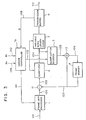
- the apparatus comprises a frame skip processor 1 for performing a frame skip processing to an input picture data 101 per each frame, a subtractor 11 for performing subtraction between a remained input picture data 102 after the frame skip processing and an interframe prediction signal 107, a quantizer 2 for blocking an interframe differential signal 103 of output from the subtractor 11 and then quantizing the block [hereinafter referred to as "quantization block (QB)"] using prescribed quantization characteristics assigned by a quantization characteristics control signal 112 and outputting a quantization index 104, a quantization decoder 3 for decoding the quantization index 104 using the quantization characteristics control signal 112 and outputting a decoded differential signal 105, an adder 12, a frame memory 4 for generating the interframe prediction signal 107, a variable word length coder 5, a transmission buffer 6 for outputting a transmission picture data 113, and a conventional coding controller 7b for controlling the frame skip in the frame skip processor 1 according to a buffer occupancy 108 of the transmission buffer 6 and control of the quantization characteristics
- a frame skip processing is performed to an input picture data 101 per each frame according to a frame skip control signal 111 assigning the number of frame skip.
- a remained input picture data 102 outputted from the frame skip processor 1 is subjected to subtraction of an interframe. prediction signal 107 in the subtractor 11 at the rear stage.
- an interframe differential signal 103 reduced the temporal redundancy is generated.
- the interframe differential signal 103 is divided into quantization blocks QB, and every n x QB (n: natural number) (every prescribed quantization blocks) or every frame, quantization of the quantization blocks QB is performed using prescribed quantization characteristics assigned among a plurality of quantization characteristics using a quantization characteristics control signal 112.
- the conventional coding controller 7b outputs a frame skip control signal 112 and a quantization characteristics (quantization step size) control signal 112 according to a buffer occupancy 108 of the transmission buffer 6.
- FIG. 2 is a block constitution diagram of the conventional coding controller 7b.
- Reference numeral 81 indicates a third quantization characteristic control table.
- the quantization index 104 and the quantization characteristics control signal 112 are coded and multiplexed in the variable word length coder 5 and transmitted to the transmission buffer 6 and temporarily stored, and then transmitted as a transmission picture data 113.
- the quantization index 104 is decoded using the quantization characteristics control signal 112, and as a result of decoding the quantization index 104 a decoded differential signal 105 is outputted to the adder 12.
- the interframe prediction signal 107 is added to the decoded differential signal 105 by the adder 12, and a decoded video signal 106 is generated.
- the decoded video signal 106 is subjected to the frame delay and outputted as the interframe prediction signal 107.
- the interframe differential signal is divided into the quantization blocks QB, and the decoding control every n x QB or every frame is performed according to the buffer occupancy. Consequently, problems exist in that when the control is performed every n x QB, the picture quality may become ununiform locally resulting in deterioration of the subjective quality, and that when the control is performed every frame, since the coding control is delayed, a larger step size may be selected or the frame skip may occur frequently.
- the coding control every frame is advantageous in that relatively uniform quality is obtained in the coded picture and the control is performed to the fluctuation for a long period of the number of bits created by coding the picture depending on the content of the scene, but is disadvantageous in that as the number of bits created by coding increases, the jerky picture frame is liable to occur accompanying with the increase and the significant fluctuation of the number of frame skip.
- an object of the present invention is to provide a picture coding apparatus wherein the local deterioration of the picture quality is prevented and the delay of the coding control is decreased.
- a coding controller for receiving the degree of buffer occupancy at present from a transmission picture data output means and for outputting the quantization characteristics control signal, comprises means for calculating the number of bits created by coding the first prescribed processing unit, means for calculating the number of bits created by coding the second prescribed processing unit, and means for determining one among a plurality of quantization characteristics based on the above-mentioned two numbers of bits created by coding.
- the coding controller also comprises a frame skip controller for outputting frame skip control signals according to the buffer occupancy.
- the coding controller further comprises a normalization section for normalizing the above-mentioned two numbers of bits created by coding, so that the means for determining the quantization characteristics determines one among a plurality of quantization characteristics using the normalized output from the normalization section.
- FIG. 3 where similar parts to those in FIG. 1 are designated by the same reference numerals, a coding controller 7a determines the number of frame skip and the quantization characteristic according to a buffer occupancy 108, a video rate 109 and a frame rate 110.
- FIG. 4 is a block diagram showing constitution of the coding controller 7a in the picture coding apparatus according to an embodiment of the invention.
- a frame skip controller 71 for determining the number of frame skip outputs a frame skip control signal 111.
- the coding controller 7a comprises a first number of bits calculation section 72 for calculating the number of bits created by coding 701 n x QB, a second number of bits calculation section 73 for calculating the number of bits created by coding 702 one frame and outputting it, a first delay circuit 74 for providing delay corresponding to n x QB, a second delay circuit 75 for providing delay corresponding to one frame, a first normalization section 76 for evaluating a normalized value for the number of bits 701 per n x QB which is independent of the video rate 109 and the frame rate 110, a second normalization section 77 for evaluating a normalized value for the number of bits 702 per one frame, a first quantization characteristics control table 78 for determining prescribed quantization characteristics among a plurality of quantization characteristics using the first normalized value 705 estimated by the first normalization section 76, a second quantization characteristics control table 79 for determining prescribed quantization characteristics among a plurality of quantization characteristics using the second normalized value 706 estimated by the
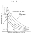
- the quantization characteristics and the number of bits created by coding have relation as shown in FIG. 5.
- the characteristic curve moves to the right upward side.
- the characteristic curve moves to the left downward side.
- several characteristic curves are previously set by a preparatory experiment, and among these curves, the characteristics corresponded to the coding results of the preceding frame (or n x QB) are selected, and this shall be made the characteristic curve in the existing frame (or n x QB).
- threshold value TH For arbitrarily determined threshold value TH, if it follows that N1 > N2 + TH the coding control is changed from every frame to every blocks.
- the number of bits I1 701 per n x QB is calculated using a buffer occupancy 703 before n x QB outputted from the first delay circuit 74 providing delay by n x QB with respect to the existing buffer occupancy 108.
- the number of bits I2 702 per frame is calculated using a buffer occupancy 704 before one frame outputted from the second delay circuit 75 providing delay by one frame with respect to the existing buffer occupancy 108.
- a normalized value being independent of a video rate R v 109 and a frame rate R f 110 is calculated for the number of bits I1 701 per n x QB and is outputted as a first normalized value N1 705. If the number of the quantization blocks per one frame is made l, relation of the first normalized value N1 705 to the number of bits I1 701 per n x QB, the video rate R v 109 and the frame rate R f 110 is expressed by following formula.
- N1 (l x I1 x R f )/(n x R v )
- a normalized value is calculated for the number of bits I2 702 per one frame, and is outputted as a second normalized value N2 706.
- N2 (I2 x R f )/R v
- prescribed quantization characteristics are determined among a plurality of quantization characteristics using the first normalized value N1 705 and the second normalized value N2 706 respectively. The determining procedure of the quantization characteristics as shown in FIG.
- first quantization characteristics control signal CS1 707 or second quantization characteristics control signal CS2 708 which were determined in the first quantization characteristics control table 78 and the second quantization characteristics control table 79 respectively is selected using the first normalized value N1 705, and is outputted as a quantization control signal 112.
- Other parts are processed in similar manner to the prior art.
- the control every n x QB and the control every frame are changed according to the normalized value of number of bits created by coding
- the variance of number of bits created by coding may be used as the criterion together with the number of bits created by coding, thereby the more suitable coding control becomes possible.
- the first quantization characteristics control signal performing the control every n x QB is generated by the first normalized value evaluating means and the first quantization characteristics control table
- the second quantization characteristics control signal performing the control every frame is generated by the second normalized value evaluating means and the second quantization characteristics control table
- either quantization characteristics control signal is selected to change the control unit by the selector according to number of bits created by coding in order to thereby effects exist in that the local deterioration of the picture quality is prevented and the delay of the coding control is decreased and the high efficiency coding of the digital video signal can be intended.
Abstract
Description
- The present invention relates to a picture coding apparatus which is intended for high efficiency coding of digital video signals.
- FIG. 1 is a block diagram showing constitution of a picture coding apparatus in the prior art operating at a definite transmission rate, such as disclosed in Murakami, Asai et al. "Adaptive Type Vector Quantization System Interframe Coding" in Technical Report IE84-1 of the Institute of Electronic and Communication Engineers in Japan (April 3, 1984). In FIG. 1, the apparatus comprises a
frame skip processor 1 for performing a frame skip processing to aninput picture data 101 per each frame, asubtractor 11 for performing subtraction between a remainedinput picture data 102 after the frame skip processing and aninterframe prediction signal 107, aquantizer 2 for blocking an interframedifferential signal 103 of output from thesubtractor 11 and then quantizing the block [hereinafter referred to as "quantization block (QB)"] using prescribed quantization characteristics assigned by a quantizationcharacteristics control signal 112 and outputting aquantization index 104, a quantization decoder 3 for decoding thequantization index 104 using the quantizationcharacteristics control signal 112 and outputting a decodeddifferential signal 105, anadder 12, aframe memory 4 for generating theinterframe prediction signal 107, a variable word length coder 5, atransmission buffer 6 for outputting atransmission picture data 113, and aconventional coding controller 7b for controlling the frame skip in theframe skip processor 1 according to abuffer occupancy 108 of thetransmission buffer 6 and control of the quantization characteristics in thequantizer 2. - Next, operation will be described. First, in the
frame skip processor 1, a frame skip processing is performed to aninput picture data 101 per each frame according to a frameskip control signal 111 assigning the number of frame skip. A remainedinput picture data 102 outputted from theframe skip processor 1 is subjected to subtraction of an interframe.prediction signal 107 in thesubtractor 11 at the rear stage. As a result, an interframedifferential signal 103 reduced the temporal redundancy is generated. In thequantizer 2, the interframedifferential signal 103 is divided into quantization blocks QB, and every n x QB (n: natural number) (every prescribed quantization blocks) or every frame, quantization of the quantization blocks QB is performed using prescribed quantization characteristics assigned among a plurality of quantization characteristics using a quantizationcharacteristics control signal 112. Theconventional coding controller 7b outputs a frameskip control signal 112 and a quantization characteristics (quantization step size)control signal 112 according to abuffer occupancy 108 of thetransmission buffer 6. FIG. 2 is a block constitution diagram of theconventional coding controller 7b.Reference numeral 81 indicates a third quantization characteristic control table. Relation of thebuffer occupancy 108 and the quantization characteristics (quantization step size) G and the number of the frame skip M is shown as follows.
B : small ⇒ G and M : small
(⇒ number of bits created by coding I : increase)
B : large ⇒ G and M : large
(⇒ number of bits created by coding I : decrease) - The
quantization index 104 and the quantizationcharacteristics control signal 112 are coded and multiplexed in the variable word length coder 5 and transmitted to thetransmission buffer 6 and temporarily stored, and then transmitted as atransmission picture data 113. In the quantization decoder 3, thequantization index 104 is decoded using the quantizationcharacteristics control signal 112, and as a result of decoding the quantization index 104 a decodeddifferential signal 105 is outputted to theadder 12. Theinterframe prediction signal 107 is added to the decodeddifferential signal 105 by theadder 12, and a decodedvideo signal 106 is generated. In theframe memory 4, the decodedvideo signal 106 is subjected to the frame delay and outputted as theinterframe prediction signal 107. - Since the picture coding apparatus in the prior art is constituted as above described, the interframe differential signal is divided into the quantization blocks QB, and the decoding control every n x QB or every frame is performed according to the buffer occupancy. Consequently, problems exist in that when the control is performed every n x QB, the picture quality may become ununiform locally resulting in deterioration of the subjective quality, and that when the control is performed every frame, since the coding control is delayed, a larger step size may be selected or the frame skip may occur frequently.
- In other words, the coding control every frame is advantageous in that relatively uniform quality is obtained in the coded picture and the control is performed to the fluctuation for a long period of the number of bits created by coding the picture depending on the content of the scene, but is disadvantageous in that as the number of bits created by coding increases, the jerky picture frame is liable to occur accompanying with the increase and the significant fluctuation of the number of frame skip. On the other hand, in the coding control every blocks (n x QB) where one picture frame is blocked (for example, 4 pixels by 4 lines), advantages exist in that the number of frame skip is relatively constant and the control is performed to the fluctuation for a short period of the number of bits created by coding the picture in each portion of the scene, but disadvantages exist in that the coding distortion is concentrated to a specific portion on the picture frame and the unnatural picture quality is liable to occur.
- In order to solve the above-mentioned problems in the prior art, an object of the present invention is to provide a picture coding apparatus wherein the local deterioration of the picture quality is prevented and the delay of the coding control is decreased.
- In order to attain the foregoing object, in a picture coding apparatus according to one aspect of the invention, a coding controller for receiving the degree of buffer occupancy at present from a transmission picture data output means and for outputting the quantization characteristics control signal, comprises means for calculating the number of bits created by coding the first prescribed processing unit, means for calculating the number of bits created by coding the second prescribed processing unit, and means for determining one among a plurality of quantization characteristics based on the above-mentioned two numbers of bits created by coding.
- The coding controller also comprises a frame skip controller for outputting frame skip control signals according to the buffer occupancy.
- The coding controller further comprises a normalization section for normalizing the above-mentioned two numbers of bits created by coding, so that the means for determining the quantization characteristics determines one among a plurality of quantization characteristics using the normalized output from the normalization section.
- The foregoing and other objects and novel features of the invention will be more fully apparent from the following detailed description when the same is read in connection with the accompanying drawings.
-
- FIG. 1 is a block diagram illustrating constitution of a picture coding apparatus in the prior art;
- FIG. 2 is a block diagram illustrating constitution of a coding controller in the prior art;
- FIG. 3 is a block diagram illustrating constitution of a picture coding apparatus as an embodiment of the invention;
- FIG. 4 is a block diagram illustrating constitution of a coding controller as an embodiment of the invention; and
- FIG. 5 is an explanation diagram illustrating relation of the quantization characteristics and the normalized number of bits created by coding.
- A preferred embodiment of the invention will now be described in detail referring to the accompanying drawings. In FIG. 3 where similar parts to those in FIG. 1 are designated by the same reference numerals, a
coding controller 7a determines the number of frame skip and the quantization characteristic according to abuffer occupancy 108, avideo rate 109 and aframe rate 110. FIG. 4 is a block diagram showing constitution of thecoding controller 7a in the picture coding apparatus according to an embodiment of the invention. In FIG. 4, aframe skip controller 71 for determining the number of frame skip outputs a frameskip control signal 111. Thecoding controller 7a comprises a first number ofbits calculation section 72 for calculating the number of bits created bycoding 701 n x QB, a second number ofbits calculation section 73 for calculating the number of bits created bycoding 702 one frame and outputting it, afirst delay circuit 74 for providing delay corresponding to n x QB, asecond delay circuit 75 for providing delay corresponding to one frame, afirst normalization section 76 for evaluating a normalized value for the number ofbits 701 per n x QB which is independent of thevideo rate 109 and theframe rate 110, asecond normalization section 77 for evaluating a normalized value for the number ofbits 702 per one frame, a first quantization characteristics control table 78 for determining prescribed quantization characteristics among a plurality of quantization characteristics using the first normalizedvalue 705 estimated by thefirst normalization section 76, a second quantization characteristics control table 79 for determining prescribed quantization characteristics among a plurality of quantization characteristics using the second normalizedvalue 706 estimated by thesecond normalization section 77, and aselector 80 for selecting either the first quantizationcharacteristics control signal 707 outputted from the first quantization characteristics control table 78 or the second quantization characteristics control signal 708 outputted from the second quantization characteristics control table 79 according to the first normalizedvalue 705. Also the apparatus comprises interframe differential signal generating means 1, 11, transmission picture data output means 2, 5, 6, decoded video signal generating means 3, 12, first normalized value evaluating means 72, 74, 76, and second normalized value evaluating means 73, 75, 77. - In general, the quantization characteristics and the number of bits created by coding have relation as shown in FIG. 5. In the picture including the large motion and complicated patterns much, the characteristic curve moves to the right upward side. On the contrary, in the picture including the small motion and simple patterns, the characteristic curve moves to the left downward side. In this embodiment, several characteristic curves are previously set by a preparatory experiment, and among these curves, the characteristics corresponded to the coding results of the preceding frame (or n x QB) are selected, and this shall be made the characteristic curve in the existing frame (or n x QB).
- For arbitrarily determined threshold value TH, if it follows that
N₁ > N₂ + TH
the coding control is changed from every frame to every blocks. - After m x n x QB (m: natural number), if it is satisfied that
N₁ ≦ N₂ + TH
the coding control is changed into every frame. - In this embodiment, for arbitrarily determined threshold value TH′, if it follows that
N₁ < N₂ + TH′
the control of every frame may be changed into the control of every blocks, thereby similar effect can be obtained. - Next, operation will be described. First, in FIG. 4, in the first number of
bits calculation section 72, the number ofbits I₁ 701 per n x QB is calculated using abuffer occupancy 703 before n x QB outputted from thefirst delay circuit 74 providing delay by n x QB with respect to the existingbuffer occupancy 108. On the contrary, in the second number ofbits calculation section 73, the number ofbits I₂ 702 per frame is calculated using abuffer occupancy 704 before one frame outputted from thesecond delay circuit 75 providing delay by one frame with respect to the existingbuffer occupancy 108. In thefirst normalization section 76, a normalized value being independent of avideo rate R v 109 and aframe rate R f 110 is calculated for the number ofbits I₁ 701 per n x QB and is outputted as a first normalizedvalue N₁ 705. If the number of the quantization blocks per one frame is made ℓ, relation of the first normalizedvalue N₁ 705 to the number ofbits I₁ 701 per n x QB, thevideo rate R v 109 and theframe rate R f 110 is expressed by following formula.
N₁ = (ℓ x I₁ x Rf)/(n x Rv)
Also in thesecond normalization section 77, a normalized value is calculated for the number ofbits I₂ 702 per one frame, and is outputted as a second normalizedvalue N₂ 706.
N₂ = (I₂ x Rf)/Rv
In the first quantization characteristic control table 78 and the second quantization characteristic control table 79, prescribed quantization characteristics are determined among a plurality of quantization characteristics using the first normalizedvalue N₁ 705 and the second normalizedvalue N₂ 706 respectively. The determining procedure of the quantization characteristics as shown in FIG. 5, is in that ① a suitable characteristic curve is selected among a plurality of characteristic curves indicating the relation of the quantization characteristics and the normalized value according to the previous relation of the quantization characteristics and the normalized value, and ② the quantization characteristics corresponding to the aimed normalized value Nt (= 1) is determined using the selected characteristic curve. In theselector 80, either first quantization characteristics controlsignal CS₁ 707 or second quantization characteristics control signal CS₂ 708 which were determined in the first quantization characteristics control table 78 and the second quantization characteristics control table 79 respectively is selected using the first normalizedvalue N₁ 705, and is outputted as aquantization control signal 112. N₁ : large ⇒ select CS₁
N₁ : small ⇒ select CS₂
Other parts are processed in similar manner to the prior art. - In this embodiment, although the control every n x QB and the control every frame are changed according to the normalized value of number of bits created by coding, in the selection of the control units of n x QB/frame, the variance of number of bits created by coding may be used as the criterion together with the number of bits created by coding, thereby the more suitable coding control becomes possible.
- According to the invention as above described, as units of the coding control, the first quantization characteristics control signal performing the control every n x QB is generated by the first normalized value evaluating means and the first quantization characteristics control table, and the second quantization characteristics control signal performing the control every frame is generated by the second normalized value evaluating means and the second quantization characteristics control table, and either quantization characteristics control signal is selected to change the control unit by the selector according to number of bits created by coding in order to thereby effects exist in that the local deterioration of the picture quality is prevented and the delay of the coding control is decreased and the high efficiency coding of the digital video signal can be intended.
Claims (5)
said coding controller comprising:
first calculation means for calculating the number of bits created by coding the first prescribed processing unit;
second calculation means for calculating the number of bits created by coding the second prescribed processing unit; and
determination means for determining the quantization characteristics for the first or second prescribed processing unit among a plurality of quantization characteristics using the output from said first and second calculation means and for outputting the quantization characteristics control signal.
said first calculation means calculating the variation of the buffer occupancy every quantization block (QB) of the prescribed number (n: natural number),
said second calculation means calculating the variation of the buffer occupancy every frame, said determining means selecting either said first or second quantization characteristics control means and outputting the quantization characteristics control signal according to the output from said first or second calculation means.
said determining means determining prescribed quantization characteristics among a plurality of quantization characteristics using outputs N₁ and N₂ from said first and second information amount normalization means respectively, and outputting the quantization characteristics control signals.
Applications Claiming Priority (2)
| Application Number | Priority Date | Filing Date | Title |
|---|---|---|---|
| JP1288180A JPH0722396B2 (en) | 1989-11-06 | 1989-11-06 | Image coding device |
| JP288180/89 | 1989-11-06 |
Publications (3)
| Publication Number | Publication Date |
|---|---|
| EP0427108A2 true EP0427108A2 (en) | 1991-05-15 |
| EP0427108A3 EP0427108A3 (en) | 1993-03-03 |
| EP0427108B1 EP0427108B1 (en) | 1995-03-15 |
Family
ID=17726847
Family Applications (1)
| Application Number | Title | Priority Date | Filing Date |
|---|---|---|---|
| EP90120901A Expired - Lifetime EP0427108B1 (en) | 1989-11-06 | 1990-10-31 | Picture coding apparatus |
Country Status (9)
| Country | Link |
|---|---|
| US (1) | US5202770A (en) |
| EP (1) | EP0427108B1 (en) |
| JP (1) | JPH0722396B2 (en) |
| KR (1) | KR930011843B1 (en) |
| AU (1) | AU627629B2 (en) |
| CA (1) | CA2028947C (en) |
| DE (1) | DE69017838T2 (en) |
| FI (1) | FI97591C (en) |
| NO (1) | NO177519C (en) |
Cited By (6)
| Publication number | Priority date | Publication date | Assignee | Title |
|---|---|---|---|---|
| FR2672407A1 (en) * | 1991-01-31 | 1992-08-07 | Graphics Communication Tech | Coding device for images in motion |
| FR2673014A1 (en) * | 1991-02-15 | 1992-08-21 | Graphics Communication Tech | IMAGE SIGNAL CODING DEVICE. |
| GB2261568A (en) * | 1991-11-15 | 1993-05-19 | Televerket | A method and a device for image coding |
| EP0647068A2 (en) * | 1993-09-30 | 1995-04-05 | Matsushita Electric Industrial Co., Ltd. | Device and method for controlling coding |
| EP0684738A3 (en) * | 1994-05-23 | 1998-05-13 | Canon Kabushiki Kaisha | Image encoding apparatus |
| US6504540B1 (en) | 1995-06-19 | 2003-01-07 | Canon Kabushiki Kaisha | Method and apparatus for altering one or more attributes of one or more blocks of image data in a document |
Families Citing this family (6)
| Publication number | Priority date | Publication date | Assignee | Title |
|---|---|---|---|---|
| US6167539A (en) * | 1991-11-14 | 2000-12-26 | Canon Kabushiki Kaisha | Transmitting apparatus with code formation based on detected transmission channel data |
| US6222943B1 (en) * | 1992-07-30 | 2001-04-24 | Canon Kabushiki Kaisha | Image reading, processing and recording with quick data compression |
| JP3224465B2 (en) * | 1993-12-22 | 2001-10-29 | シャープ株式会社 | Image coding device |
| US7082163B2 (en) * | 2000-11-20 | 2006-07-25 | Matsushita Electric Industrial Co., Ltd. | Picture coding method, picture coding apparatus and image relaying apparatus |
| US6904984B1 (en) * | 2003-06-20 | 2005-06-14 | Rock Bit L.P. | Stepped polycrystalline diamond compact insert |
| CN107968948A (en) * | 2016-10-19 | 2018-04-27 | 北京新唐思创教育科技有限公司 | Online Video playback method and system |
Citations (6)
| Publication number | Priority date | Publication date | Assignee | Title |
|---|---|---|---|---|
| JPS5761387A (en) * | 1980-09-30 | 1982-04-13 | Nippon Telegr & Teleph Corp <Ntt> | Encoder between frames |
| JPS5814688A (en) * | 1981-07-20 | 1983-01-27 | Nippon Telegr & Teleph Corp <Ntt> | Intra-frame estimation coding device |
| US4386366A (en) * | 1980-03-26 | 1983-05-31 | Fuji Photo Film Co. Ltd. | Adaptive type quantizer |
| US4394774A (en) * | 1978-12-15 | 1983-07-19 | Compression Labs, Inc. | Digital video compression system and methods utilizing scene adaptive coding with rate buffer feedback |
| EP0284161A2 (en) * | 1987-03-27 | 1988-09-28 | Philips Patentverwaltung GmbH | Source encoder for video pictures |
| JPH1018382A (en) * | 1996-06-28 | 1998-01-20 | Hokusatsu Home:Kk | Odor stop device for drain pipe |
Family Cites Families (7)
| Publication number | Priority date | Publication date | Assignee | Title |
|---|---|---|---|---|
| JPS58194456A (en) * | 1982-05-10 | 1983-11-12 | Ricoh Co Ltd | Sequential multi-address device |
| JPS60180388A (en) * | 1984-02-28 | 1985-09-14 | Kokusai Denshin Denwa Co Ltd <Kdd> | Re-quantizing system of encoded picture signal |
| EP0193185B1 (en) * | 1985-02-28 | 1992-05-13 | Mitsubishi Denki Kabushiki Kaisha | Interframe adaptive vector quantization encoding apparatus |
| JPH065888B2 (en) * | 1986-02-14 | 1994-01-19 | 富士写真フイルム株式会社 | Image data quantization method and apparatus |
| JPS62276927A (en) * | 1986-05-26 | 1987-12-01 | Mitsubishi Electric Corp | Differential pulse modulation system |
| KR910000707B1 (en) * | 1986-05-26 | 1991-01-31 | 미쓰비시덴기 가부시기가이샤 | Method and apparatus for encoding transmitting |
| US4785356A (en) * | 1987-04-24 | 1988-11-15 | International Business Machines Corporation | Apparatus and method of attenuating distortion introduced by a predictive coding image compressor |
-
1989
- 1989-11-06 JP JP1288180A patent/JPH0722396B2/en not_active Expired - Lifetime
-
1990
- 1990-10-30 AU AU65626/90A patent/AU627629B2/en not_active Ceased
- 1990-10-30 CA CA002028947A patent/CA2028947C/en not_active Expired - Fee Related
- 1990-10-30 US US07/605,362 patent/US5202770A/en not_active Expired - Lifetime
- 1990-10-31 EP EP90120901A patent/EP0427108B1/en not_active Expired - Lifetime
- 1990-10-31 DE DE69017838T patent/DE69017838T2/en not_active Expired - Fee Related
- 1990-11-01 NO NO904753A patent/NO177519C/en unknown
- 1990-11-05 KR KR1019900017815A patent/KR930011843B1/en not_active IP Right Cessation
- 1990-11-05 FI FI905469A patent/FI97591C/en not_active IP Right Cessation
Patent Citations (6)
| Publication number | Priority date | Publication date | Assignee | Title |
|---|---|---|---|---|
| US4394774A (en) * | 1978-12-15 | 1983-07-19 | Compression Labs, Inc. | Digital video compression system and methods utilizing scene adaptive coding with rate buffer feedback |
| US4386366A (en) * | 1980-03-26 | 1983-05-31 | Fuji Photo Film Co. Ltd. | Adaptive type quantizer |
| JPS5761387A (en) * | 1980-09-30 | 1982-04-13 | Nippon Telegr & Teleph Corp <Ntt> | Encoder between frames |
| JPS5814688A (en) * | 1981-07-20 | 1983-01-27 | Nippon Telegr & Teleph Corp <Ntt> | Intra-frame estimation coding device |
| EP0284161A2 (en) * | 1987-03-27 | 1988-09-28 | Philips Patentverwaltung GmbH | Source encoder for video pictures |
| JPH1018382A (en) * | 1996-06-28 | 1998-01-20 | Hokusatsu Home:Kk | Odor stop device for drain pipe |
Non-Patent Citations (4)
| Title |
|---|
| IEEE JOURNAL ON SELECTED AREAS OF COMMUNICATIONS vol. 4, no. 8, November 1986, NEW YORK, US; pages 1202 - 1209 H.YAMAGUCHI 'A 64kbit/s integrated visual communication system - New communication medium for the ISDN' * |
| PATENT ABSTRACTS OF JAPAN vol. 13, no. 196 (E-755)10 May 1989 & JP-A-10 18 382 ( MITSUBISHI ELECTRIC CORP. ) 23 January 1989 * |
| PATENT ABSTRACTS OF JAPAN vol. 6, no. 136 (E-120)(1014) 23 July 1982 & JP-A-57 61 387 ( NIPPON DENSHIN DENWA KOSHA ) * |
| PATENT ABSTRACTS OF JAPAN vol. 7, no. 88 (E-170)(1233) 12 April 1983 & JP-A-58 14 688 ( NIPPON DENSHIN DENWA KOSHA ) * |
Cited By (10)
| Publication number | Priority date | Publication date | Assignee | Title |
|---|---|---|---|---|
| FR2672407A1 (en) * | 1991-01-31 | 1992-08-07 | Graphics Communication Tech | Coding device for images in motion |
| FR2673014A1 (en) * | 1991-02-15 | 1992-08-21 | Graphics Communication Tech | IMAGE SIGNAL CODING DEVICE. |
| GB2261568A (en) * | 1991-11-15 | 1993-05-19 | Televerket | A method and a device for image coding |
| GB2261568B (en) * | 1991-11-15 | 1995-03-22 | Televerket | A method and a device for image coding |
| EP0647068A2 (en) * | 1993-09-30 | 1995-04-05 | Matsushita Electric Industrial Co., Ltd. | Device and method for controlling coding |
| EP0647068A3 (en) * | 1993-09-30 | 1996-05-01 | Matsushita Electric Ind Co Ltd | Device and method for controlling coding. |
| US5592225A (en) * | 1993-09-30 | 1997-01-07 | Matsushita Electric Industrial Co., Ltd. | Device and method for controlling coding |
| EP0684738A3 (en) * | 1994-05-23 | 1998-05-13 | Canon Kabushiki Kaisha | Image encoding apparatus |
| US6256413B1 (en) | 1994-05-23 | 2001-07-03 | Canon Kabushiki Kaisha | Image encoding apparatus |
| US6504540B1 (en) | 1995-06-19 | 2003-01-07 | Canon Kabushiki Kaisha | Method and apparatus for altering one or more attributes of one or more blocks of image data in a document |
Also Published As
| Publication number | Publication date |
|---|---|
| DE69017838T2 (en) | 1995-12-14 |
| AU627629B2 (en) | 1992-08-27 |
| KR930011843B1 (en) | 1993-12-21 |
| FI97591C (en) | 1997-01-10 |
| CA2028947C (en) | 1994-04-12 |
| NO177519C (en) | 1995-09-27 |
| DE69017838D1 (en) | 1995-04-20 |
| FI97591B (en) | 1996-09-30 |
| NO904753D0 (en) | 1990-11-01 |
| NO904753L (en) | 1991-05-07 |
| NO177519B (en) | 1995-06-19 |
| CA2028947A1 (en) | 1991-05-07 |
| JPH0722396B2 (en) | 1995-03-08 |
| EP0427108A3 (en) | 1993-03-03 |
| FI905469A0 (en) | 1990-11-05 |
| US5202770A (en) | 1993-04-13 |
| KR910011051A (en) | 1991-06-29 |
| AU6562690A (en) | 1991-05-09 |
| JPH03149984A (en) | 1991-06-26 |
| EP0427108B1 (en) | 1995-03-15 |
Similar Documents
| Publication | Publication Date | Title |
|---|---|---|
| US4707738A (en) | Adaptive process for the coding and decoding of a sequence of pictures by transformation and devices for performing this process | |
| US5049990A (en) | Highly efficient coding apparatus | |
| US4722003A (en) | High efficiency coding apparatus | |
| EP0385654B1 (en) | Highly efficient coding apparatus | |
| EP0473384B1 (en) | Coding apparatus for digital image signals | |
| US4179710A (en) | Predictive encoder with a non-linear quantizing characteristic | |
| EP0535960B1 (en) | Coding signal processor | |
| EP0249086B1 (en) | Method and apparatus for encoding/transmitting image | |
| US7154949B2 (en) | Picture coding device and method, picture transmitting device and method and recording medium | |
| US5721589A (en) | Moving picture coding apparatus which calculates an optimum quantization step size using the relationship between the quantization step size and a generated bit amount | |
| JPH0797753B2 (en) | Encoding output data amount control method | |
| EP0427108A2 (en) | Picture coding apparatus | |
| JP3423831B2 (en) | Transmitter and method for constant rate transmission of digital information | |
| US5521643A (en) | Adaptively coding method and apparatus utilizing variation in quantization step size | |
| US5949956A (en) | Variable bit rate video encoder, and video recorder, including code amount allocation | |
| JPH0821866B2 (en) | Information control circuit | |
| US5508745A (en) | Apparatus for controlling a quantization level to be modified by a motion vector | |
| US5905578A (en) | Coding apparatus | |
| EP0545875A1 (en) | Method for image coding of a video signal | |
| JP2000059792A (en) | High efficiency encoding device of dynamic image signal | |
| JP3152148B2 (en) | Image coding device | |
| JPH06113271A (en) | Picture signal coding device | |
| JPH11317942A (en) | Image coder | |
| JPH0783480B2 (en) | Interframe coding device | |
| JPH11205791A (en) | Image coding method and image encoder |
Legal Events
| Date | Code | Title | Description |
|---|---|---|---|
| PUAI | Public reference made under article 153(3) epc to a published international application that has entered the european phase |
Free format text: ORIGINAL CODE: 0009012 |
|
| AK | Designated contracting states |
Kind code of ref document: A2 Designated state(s): DE FR GB IT NL SE |
|
| PUAL | Search report despatched |
Free format text: ORIGINAL CODE: 0009013 |
|
| AK | Designated contracting states |
Kind code of ref document: A3 Designated state(s): DE FR GB IT NL SE |
|
| 17P | Request for examination filed |
Effective date: 19930823 |
|
| 17Q | First examination report despatched |
Effective date: 19931005 |
|
| GRAA | (expected) grant |
Free format text: ORIGINAL CODE: 0009210 |
|
| AK | Designated contracting states |
Kind code of ref document: B1 Designated state(s): DE FR GB IT NL SE |
|
| ITF | It: translation for a ep patent filed |
Owner name: ING. C. GREGORJ S.P.A. |
|
| REF | Corresponds to: |
Ref document number: 69017838 Country of ref document: DE Date of ref document: 19950420 |
|
| ET | Fr: translation filed | ||
| PGFP | Annual fee paid to national office [announced via postgrant information from national office to epo] |
Ref country code: FR Payment date: 19950918 Year of fee payment: 6 |
|
| PGFP | Annual fee paid to national office [announced via postgrant information from national office to epo] |
Ref country code: SE Payment date: 19951023 Year of fee payment: 6 |
|
| PLBE | No opposition filed within time limit |
Free format text: ORIGINAL CODE: 0009261 |
|
| STAA | Information on the status of an ep patent application or granted ep patent |
Free format text: STATUS: NO OPPOSITION FILED WITHIN TIME LIMIT |
|
| 26N | No opposition filed | ||
| REG | Reference to a national code |
Ref country code: GB Ref legal event code: 746 Effective date: 19960611 |
|
| PGFP | Annual fee paid to national office [announced via postgrant information from national office to epo] |
Ref country code: GB Payment date: 19961022 Year of fee payment: 7 |
|
| PGFP | Annual fee paid to national office [announced via postgrant information from national office to epo] |
Ref country code: NL Payment date: 19961029 Year of fee payment: 7 |
|
| PG25 | Lapsed in a contracting state [announced via postgrant information from national office to epo] |
Ref country code: SE Effective date: 19961101 |
|
| PGFP | Annual fee paid to national office [announced via postgrant information from national office to epo] |
Ref country code: DE Payment date: 19961108 Year of fee payment: 7 |
|
| PG25 | Lapsed in a contracting state [announced via postgrant information from national office to epo] |
Ref country code: FR Effective date: 19970630 |
|
| EUG | Se: european patent has lapsed |
Ref document number: 90120901.5 |
|
| REG | Reference to a national code |
Ref country code: FR Ref legal event code: ST |
|
| PG25 | Lapsed in a contracting state [announced via postgrant information from national office to epo] |
Ref country code: GB Free format text: LAPSE BECAUSE OF NON-PAYMENT OF DUE FEES Effective date: 19971031 |
|
| PG25 | Lapsed in a contracting state [announced via postgrant information from national office to epo] |
Ref country code: NL Free format text: LAPSE BECAUSE OF NON-PAYMENT OF DUE FEES Effective date: 19980501 |
|
| GBPC | Gb: european patent ceased through non-payment of renewal fee |
Effective date: 19971031 |
|
| NLV4 | Nl: lapsed or anulled due to non-payment of the annual fee |
Effective date: 19980501 |
|
| PG25 | Lapsed in a contracting state [announced via postgrant information from national office to epo] |
Ref country code: DE Free format text: LAPSE BECAUSE OF NON-PAYMENT OF DUE FEES Effective date: 19980701 |
|
| PG25 | Lapsed in a contracting state [announced via postgrant information from national office to epo] |
Ref country code: IT Free format text: LAPSE BECAUSE OF NON-PAYMENT OF DUE FEES Effective date: 20051031 |