EP0427010B1 - Verschluss zum Verschliessen von Beuteln sowie Verfahren zu dessen Herstellung - Google Patents
Verschluss zum Verschliessen von Beuteln sowie Verfahren zu dessen Herstellung Download PDFInfo
- Publication number
- EP0427010B1 EP0427010B1 EP90119766A EP90119766A EP0427010B1 EP 0427010 B1 EP0427010 B1 EP 0427010B1 EP 90119766 A EP90119766 A EP 90119766A EP 90119766 A EP90119766 A EP 90119766A EP 0427010 B1 EP0427010 B1 EP 0427010B1
- Authority
- EP
- European Patent Office
- Prior art keywords
- profile
- knobs
- closure
- fastener
- protrusions
- Prior art date
- Legal status (The legal status is an assumption and is not a legal conclusion. Google has not performed a legal analysis and makes no representation as to the accuracy of the status listed.)
- Expired - Lifetime
Links
Images


Classifications
-
- B—PERFORMING OPERATIONS; TRANSPORTING
- B65—CONVEYING; PACKING; STORING; HANDLING THIN OR FILAMENTARY MATERIAL
- B65D—CONTAINERS FOR STORAGE OR TRANSPORT OF ARTICLES OR MATERIALS, e.g. BAGS, BARRELS, BOTTLES, BOXES, CANS, CARTONS, CRATES, DRUMS, JARS, TANKS, HOPPERS, FORWARDING CONTAINERS; ACCESSORIES, CLOSURES, OR FITTINGS THEREFOR; PACKAGING ELEMENTS; PACKAGES
- B65D33/00—Details of, or accessories for, sacks or bags
- B65D33/16—End- or aperture-closing arrangements or devices
- B65D33/25—Riveting; Dovetailing; Screwing; using press buttons or slide fasteners
- B65D33/2508—Riveting; Dovetailing; Screwing; using press buttons or slide fasteners using slide fasteners with interlocking members having a substantially uniform section throughout the length of the fastener; Sliders therefor
- B65D33/2541—Riveting; Dovetailing; Screwing; using press buttons or slide fasteners using slide fasteners with interlocking members having a substantially uniform section throughout the length of the fastener; Sliders therefor characterised by the slide fastener, e.g. adapted to interlock with a sheet between the interlocking members having sections of particular shape
-
- A—HUMAN NECESSITIES
- A44—HABERDASHERY; JEWELLERY
- A44B—BUTTONS, PINS, BUCKLES, SLIDE FASTENERS, OR THE LIKE
- A44B19/00—Slide fasteners
- A44B19/10—Slide fasteners with a one-piece interlocking member on each stringer tape
- A44B19/16—Interlocking member having uniform section throughout the length of the stringer
-
- Y—GENERAL TAGGING OF NEW TECHNOLOGICAL DEVELOPMENTS; GENERAL TAGGING OF CROSS-SECTIONAL TECHNOLOGIES SPANNING OVER SEVERAL SECTIONS OF THE IPC; TECHNICAL SUBJECTS COVERED BY FORMER USPC CROSS-REFERENCE ART COLLECTIONS [XRACs] AND DIGESTS
- Y10—TECHNICAL SUBJECTS COVERED BY FORMER USPC
- Y10S—TECHNICAL SUBJECTS COVERED BY FORMER USPC CROSS-REFERENCE ART COLLECTIONS [XRACs] AND DIGESTS
- Y10S24/00—Buckles, buttons, clasps
- Y10S24/30—Separable-fastener or required component thereof
- Y10S24/50—Separable-fastener or required component thereof including member having elongated, resilient, interlocking face with identical, parallel cross-sections throughout its length
-
- Y—GENERAL TAGGING OF NEW TECHNOLOGICAL DEVELOPMENTS; GENERAL TAGGING OF CROSS-SECTIONAL TECHNOLOGIES SPANNING OVER SEVERAL SECTIONS OF THE IPC; TECHNICAL SUBJECTS COVERED BY FORMER USPC CROSS-REFERENCE ART COLLECTIONS [XRACs] AND DIGESTS
- Y10—TECHNICAL SUBJECTS COVERED BY FORMER USPC
- Y10T—TECHNICAL SUBJECTS COVERED BY FORMER US CLASSIFICATION
- Y10T24/00—Buckles, buttons, clasps, etc.
- Y10T24/45—Separable-fastener or required component thereof [e.g., projection and cavity to complete interlock]
- Y10T24/45152—Each mating member having similarly shaped, sized, and operated interlocking or intermeshable face
- Y10T24/45157—Zipper-type [e.g., slider]
- Y10T24/45168—Zipper-type [e.g., slider] for container [e.g., bag]
Definitions
- the invention relates to a closure, preferably made of plastic, for closing bags in accordance with the preamble of claim 1. Furthermore, the invention relates to a bag, preferably made of plastic, and a method for producing a closure or a bag.
- a closure preferably made of plastic, for closing prey is known, which consists of a male profile and a female profile, which are each connected to a film and the are releasably connectable.
- US-PS 42 63 079 a closure is known which can be extruded from a nozzle onto a prefabricated film. It is also possible to extrude the closure by itself from a nozzle and then to connect it to a film by welding or gluing.
- closures or sealing bags the use of which has the meaning and purpose, to be used several times in order to keep the filling - especially in department stores and retail stores - tightly closed, lying open after a single opening and dusting the goods . Few users can easily lock the known narrow, thin single-groove closures of the type specified above.
- the female profile of the closure which is intended to accommodate the male profile, that is to say the single hook, is stiffer in itself due to the necessarily reinforced back, so that when trying, the known closure or pouch does not come from the closure edge or pouch edge from closing, but from the middle, the male profile, i.e. the single hook, dodges too easily, so that the inexperienced user cannot bring the single hook exactly into the female profile.
- DE-A 3 032 889 discloses a closure, preferably made of plastic, for closing bags, which consists of a male profile and a female profile, each of which is connected to a film and which can be detachably connected to one another.
- This closure is provided on a container having flexible first and second side walls. The reclosable end of the first side wall extends beyond the end edge of the second side wall.
- On the surface of the first side wall a first and a second web are arranged at a distance from one another essentially parallel to the first closure profile. The first web runs close to the end edge of the first side wall, while the second web lies substantially opposite the end edge of the second side wall when the closure profiles are in engagement with one another.
- a third web is arranged on the surface of the second side wall substantially parallel to the second closure profile near the end edge of the second side wall. This configuration is intended to make it particularly easy to open the container.
- EP-A-241 334 discloses a closure for pipe insulation which has two spaced, continuous knobs on the side of the closure tape facing away from the profiles. These knobs are arranged at a relatively large distance from the profiles. They only serve to stabilize the flags after they have been welded onto the tube in order to avoid subsequent corrugation.
- a closure preferably made of plastic, for closing bags according to the preamble of claim 1 is known from FR-A 2 620 377. With this closure, there are two spaced, continuous knobs on the side of the film facing away from the male profile and lying on different sides of the profile provided that serve the stabilization.
- the object of the invention is to further develop a closure of the type specified at the outset such that it can be easily closed with simple and inexpensive production.
- this object is achieved by the features specified in the characterizing part of claim 1.
- the continuous knobs are higher than the intervening parts of the profile for a tactile feeling when closing the lock.
- a clear guidance through the two noticeable raised knobs is felt when streaking along the closure with the thumb and forefinger, so that the male profile is guided in a straight direction when the closure is gripped (closed).
- the knobs which are relatively small in relation to the profile, are attached to the back of the male profile, ie they point in the opposite direction to the male profile. Since the knobs are relatively small, very little material is required for their manufacture, which means that the closure can be produced very inexpensively. The knobs can be easily attached. The closure is easy to close because the knobs provide very good guidance.
- EP-A-114 373 From EP-A-114 373 it is known to stiffen the male profile by means of ribs which extend in the same direction as the male profile and which are spaced apart from the male profile. The ribs lie on different sides of the male profile and point in the same direction.
- This closure described in the cited EP-A-114 373 has the disadvantage that a considerably greater consumption of material takes place, namely due to the relatively large ribs and the additionally existing, reinforced back.
- the ribs are essentially the same size as the male profile. All of this has a negative impact on manufacturing costs and is also undesirable for environmental reasons (disposal). The manufacture of the tools is also more difficult since the respective nozzles (extrusion nozzles) have to be adjusted in a relatively complex manner.
- EP-A-223 125 A solution is known from EP-A-223 125 in which two webs are attached to the left and right of the male profile, which webs point in the same direction as the male profile. However, the back strength of the profile is reduced. However, the webs involve considerably more material than the knobs proposed here. It is also disadvantageous in the embodiment according to EP-A-223 125 that when the two profile parts are pressed together and when they are slid along to close the Profile of the thumb only feels the slight increase that is provided immediately below the male profile and that cannot be avoided for rheological reasons. The guidance of the thumb when closing the profile is therefore poor. In contrast, the knobs proposed here lead the thumb much better when the profile is closed.
- the knobs stabilize the male profile sufficiently so that the end user (user) can not only close the closure more easily from the edge of the bag, but can also engage the closure strips anywhere in the middle of the bag or closure, to close the shutter.
- knobs lie on the back of the profile, ie on the outside of the closure or the bag.
- the male profile and the knobs point in opposite directions.
- This arrangement has the advantage that after the first pressing of the profile parts into each other and the subsequent streaking with the thumb and index finger, the thumb feels a very clear guidance through the two noticeable rising knobs and thus unconsciously the male profile when the closure is closed (closed) straight direction. It is achieved by a simple but greatly improved design that the disadvantages known hitherto are avoided and nevertheless an easier and safer closing of the closure parts is ensured, all this with the least possible material expenditure.
- Two continuous knobs can be provided. This achieves sufficient stabilization with a minimum of material. In certain applications, it is advantageous if four continuous knobs are provided, since this achieves greater stabilization or stiffening.
- knobs are preferably colored. These colored knobs also represent a locking aid purely optically.
- the invention further relates to a bag, preferably made of plastic, characterized by a closure of the type specified above.
- the closure is preferably in one piece with the bag.
- the invention further relates to a method for producing a closure of the type specified above or for producing a bag of the type specified above. According to the invention it is provided that the foils and the knobs or the bag and the closure are extruded from a tool in one operation . It is possible to extrude one or more knobs in color.
- the method for attaching the knobs represents a further advantage over the known closures. Because the knobs are attached to the back of the profile, ie beyond the direction of the profile, the profile nozzle can be produced undisturbed by unpleasant influences.
- a tool for producing a closure or a bag of the type specified above consists of a ring and a core, which form an annular gap between them. Radially outside the annular gap, channels for material feed are provided, which are used to produce the knobs. A side extruder is preferably provided for these channels. The material required to produce the knobs is fed into the channels through this auxiliary extruder.
- the side extruder can supply colored material, so that colored knobs can be produced particularly easily in this way.
- the male profile 1 is connected or hooked to the female profile 2.
- the female profile 2 consists of a hook profile 5 and a profile part 6 without a hook.
- the hook of the male profile 1 is complementary to that of the profile part 5 of the female part.
- the male profile 1 is connected in one piece with a film 3, the female profile 2 is connected in one piece with the other film 4.
- the male profile 1 has a reinforced back 7 on the side of the film 3 opposite the profile.
- Fig. 2 shows a closure made of plastic for closing bags, consisting of a male profile 1 and a female profile 2, which consists of the hook part 5 and the profile part 6, both the male profile 1 and the female profile 2 with are each connected to a film 3, 4.
- a male profile 1 and a female profile 2 which consists of the hook part 5 and the profile part 6, both the male profile 1 and the female profile 2 with are each connected to a film 3, 4.
- By hooking are the male profile and the female Profile releasably connectable.
- two spaced, continuous knobs 8 are provided on the side of the film 3 facing away from the male profile 1, two spaced, continuous knobs 8 are provided.
- the knobs 8 are integrally connected to the film 3.
- FIG. 1 only the knobs 8 of the previously known reinforced back (FIG. 1) are left, while the remaining profile back 7 is thinned out and is essentially no thicker than the film itself.
- the contour of FIG 2 is represented in FIG. 1 by the dashed line 9.
- knobs 8 are provided instead of two knobs in order to obtain greater stabilization of the film.
- knobs 9 can be provided on the side of the other film 4 facing away from the female profile 2, that is to say the film 4 belonging to the female profile 2, several, in the illustrated case two, spaced, continuous knobs 9 can be provided.
- the knobs 8, 9 are essentially semicircular in cross section. However, other cross-sectional shapes are also possible.
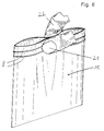
- FIG. 5 it can be seen how the two knobs are touched by the thumb 21 when closing and the thumb thereby feels a very clear guidance through these two elevations (knobs) and so unconsciously leads the male profile in a straight direction when the closure is engaged .
- Another finger 22 of the same hand lies opposite the thumb 21, generally the index finger.
- Fig. 6 shows a closure bag 10 of the type described, which by stiffening the knobs 8 in the closure part at the upper end of the bag 10 with thumb 21 and index finger 22 of the middle can be closed by simply pressing it in without the locking parts evading laterally.
- the knobs 8 have a stiffening effect here, in a manner similar to that in the case of thin sheet metal, short corrugations or applied strips can bring about an enormous stiffening. If the male profile consists of only a single hook, this inevitably moves to the side when a bag is pressed in from the center (as shown in FIG. 6) and does not hit the female part if there are no knobs.
- the knobs 8 make it possible to reliably close the closure also from the center, as shown in FIG. 6.
- Stiffeners in the form of ribs are already known from EP-A-114 373 and from EP-A-223 125. There, however, the ribs always point in the same direction as the profile. The fact that the knobs 8 and 9 point in the opposite direction to the associated profile increases the overall cross section or the entire length of the cross section, which also increases the overall rigidity.
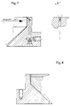
- the tool consists of a ring 11 which encloses a core 12. Plastic material flows from the extruder into the tool from below through the ring channel 13 between the ring 11 and the core 12. It finally flows out of an annular nozzle 15 through the narrow gap 14 and thus forms a plastic tube.
- a side extruder mouthpiece 16 is the knob on the through a bore 17 and a narrower channel 18 directly on the upper edge of the ring 11 sprayed plastic hose.
- the channel 18 opens into the gap 14 in such a way that the hump is formed.
- the bore 17 divides into two channels 18 in order to produce both hops. If more knobs are to be produced, more channels can be arranged accordingly.
- FIG. 8 shows another tool without a side extruder.
- This tool also consists of an outer ring 11 and a core 12 arranged therein, which delimit between them the ring channel 13 through which the plastic material flows to the ring nozzle 15.
- a channel 19 on the cylindrical part of the ring 11 more material is supplied to the exiting hose at this point, so that the desired hop is created.
- One channel 19 is provided per hop.
- the knob is larger or smaller; it can be determined in the desired way.
- knobs 8 and 9 further knobs which point inwards, that is to say in the same direction as the associated profile part.
- the inward-facing knobs can lie at the same point as the associated outward-pointing knobs 8 or 9.
- the inward-pointing knobs can be arranged at a distance from the outward-facing knobs 8 and 9. These additional, inwardly facing knobs serve for further stabilization.
- FIG. 4 The embodiment shown in FIG. 4 with four knobs 8 on the film 3 of the male profile 1 and two knobs 9 on the film 4 of the female profile 2 is particularly recommended for the profile shown in Fig. 4, which is known from EP-A-223 125. There the back of both the male profile and the female profile is so thin that there is no stabilization. This stabilization is brought about by the knobs 8, 9.
Description
- Die Erfindung betrifft einen Verschluß, vorzugsweise aus Kunststoff, zum Verschließen von Beutein nach dem Oberbegriff des Anspruchs 1. Weiterhin betrifft die Erfindung einen Beutel, vorzugsweise aus Kunststoff, und ein Verfahren zur Herstellung eines Verschlusses oder eines Beutels.
- Aus der DE-PS 14 86 627 oder der DE-PS 19 50 724 ist ein Verschluß, vorzugsweise aus Kunststoff, zum Verschließen von Beutein bekannt, der aus einem männlichen Profil und einem weiblichen Profil besteht, die mit jeweils einer Folie verbunden sind und die miteinander lösbar verbindbar sind. Aus der US-PS 42 63 079 ist ein Verschluß bekannt, der aus einer Düse auf eine vorgefertigte Folie aufextrudiert werden kann. Es ist auch möglich, den Verschluß für sich alleine aus einer Düse zu extrudieren und ihn dann durch Schweißen oder Kleben mit einer Folie zu verbinden.
- Bisher wurde vor allem darauf geachtet, die bekannten Verschlüsse in kleinsten Dimensionen herzustellen, zum einen wegen der Materialersparnis, zum anderen aber auch deshalb, um ein leichteres Querschweißen auf den sogenannten Beutelmaschinen zu ermöglichen, da jede Verstärkung des Verschlußteiles beim anschließenden Trennschweißen, bei dem aus der Verschlußfolie Beutel hergestellt werden, den Schweißvorgang verlangsamt oder zusätzliche Einrichtungen erfordert.
- Der Nachteil der bekannten Verschlüsse liegt darin, daß das männliche Profil, also der freistehende Einzelhaken, zu leicht nach der Seite ausweicht, so daß der nicht geübte Benutzer solcher Verschlüsse bzw. Beutel oftmals Schwierigkeiten beim Schließen des Verschlusses bzw. des Beutels hat. Es hat sich gezeigt, daß derartige Verschlüsse bzw. Verschlußbeutel, deren Anwendung den Sinn und Zweck haben, mehrmals verwendet zu werden, um das Füllgut - vor allem in Kaufhäusern und Einzelhandelsgeschäften - immer wieder dicht abzuschließen, nach einmaligem Öffnen offen herumliegen und die Ware verstaubt. Die wenigsten Benutzer können die vorbekannten schmalen, dünnen Einrillen-Verschlüsse der oben angegebenen Art ohne weiteres verschließen.
- Bei den eingangs angegebenen Verschlüssen ist das weibliche Profil des Verschlusses, das das männliche Profil, also den Einzelhaken, aufnehmen soll, durch den notwendigerweise verstärkten Rücken in sich steifer, so daß beim Versuch, den vorbekannten Verschluß bzw. Beutel nicht vom Verschlußrand bzw. Beutelrand aus zu verschließen, sondern von der Mitte aus, das männliche Profil, also der Einzelhaken, zu leicht ausweicht, so daß der nicht geübte Benutzer den Einzelhaken nicht genau in das weibliche Profil bringen kann.
- Aus der DE-A 3 032 889 ist ein Verschluß, vorzugsweise aus Kunststoff, zum Verschließen von Beuteln bekannt, der aus einem männlichen Profil und einem weiblichen Profil besteht, die mit jeweils einer Folie verbunden sind und die miteinander lösbar verbindbar sind. Dieser Verschluß ist an einem Behälter vorgesehen, der flexible erste und zweite Seitenwände aufweist. Die erste Seitenwand reicht an dem wiederverschließbaren Ende über die Endkante der zweiten Seitenwand hinaus. Auf der Oberfläche der ersten Seitenwand sind ein erster und ein zweiter Steg im Abstand voneinander im wesentlichen parallel zu dem ersten Verschlußprofil angeordnet. Der erste Steg verläuft nahe der Endkante der ersten Seitenwand, während der zweite Steg bei in Eingriff miteinander stehenden Verschlußprofilen im wesentlichen gegenüber der Endkante der zweiten Seitenwand liegt. Auf der Oberfläche der zweiten Seitenwand ist ein dritter Steg im wesentlichen parallel zu dem zweiten Verschlußprofil nahe der Endkante der zweiten Seitenwand angeordnet. Durch diese Ausgestaltung soll erreicht werden, daß sich der Behälter besonders leicht öffnen läßt.
- Aus der EP-A-241 334 geht ein Verschluß für eine Rohrisoliierung hervor, welcher auf der den Profilen abgewandten Seite des Verschlußbandes jeweils zwei beabstandete, durchgehende Noppen aufweist. Diese Noppen sind in einem verhältnismäßig großen Abstand von den Profilen angeordnet. Sie dienen lediglich der Stabilisierung der Fahnen, nachdem diese auf das Rohr aufgeschweißt worden sind, um eine anschließende Wellung zu vermeiden.
- Ein Verschluß, vorzugsweise aus Kunststoff, zum Verschließen von Beuteln nach dem Oberbegriff des Anspruchs 1 ist aus der FR-A 2 620 377 bekannt. Bei diesem Verschluß sind auf der dem männlichen Profil abgewandten Seite der Folie zwei beabstandete, auf verschiedenen Seite des Profils liegende, durchgehende Noppen vorgesehen, die der Stabilisierung dienen.
- Aufgabe der Erfindung ist es, einen Verschluß der eingangs angegebenen Art dahingehend weiterzuentwickeln, daß er bei einfacher und kostengünstiger Herstellung leicht verschließbar ist.
- Erfindungsgemäß wird diese Aufgabe durch die im kennzeichnenden Teil des Anspruchs 1 angegebenen Merkmale gelöst. Die durchgehenden Noppen sind zur fühlbaren Fühlung beim Verschließen des Verschlusses höher als die dazwischenliegenden Teile des Profils. Hierdurch wird beim Entlangstreifen an dem Verschluß mit Daumen und Zeigefinger eine deutliche Führung durch die beiden fühlbaren sich erhebenden Noppen verspürt, so daß das männliche Profil beim Zustreifen (Verschließen) des Verschlusses in gerader Richtung geführt wird.
- Die im Verhältnis zum Profil verhältnismäßig kleinen Noppen sind auf dem Rückenteil des männlichen Profils angebracht, weisen also in die entgegengesetzte Richtung wie das männliche Profil. Da die Noppen verhältnismäßig klein sind, wird zu ihrer Herstellung nur sehr wenig Material benötigt, wodurch der Verschluß sehr kostengünstig herstellbar ist. Die Noppen können auf einfache Weise angebracht werden. Der Verschluß ist leicht verschließbar, da die Noppen eine sehr gute Führung mit sich bringen.
- Aus der EP-A-114 373 ist es bekannt, das männliche Profil durch Rippen zu versteifen, die sich in die gleiche Richtung erstrecken wie das männliche Profil und die vom männnlichen Profil beabstandet sind. Die Rippen liegen auf verschiedenen Seiten des männlichen Profils und weisen in dieselbe Richtung. Dieser in der genannten EP-A-114 373 beschriebene Verschluß hat den Nachteil, daß ein erheblich größerer Materialverbrauch stattfindet, und zwar durch die verhältnismäßig großen Rippen und den zusätzlich noch vorhandenen, verstärkten Rücken. Die Rippen sind im wesentlichen genausogroß wie das männliche Profil. All dies wirkt sich negativ auf die Herstellkosten aus und ist außerdem auch aus Umweltschutzgründen (Entsorgung) nicht erwünscht. Auch ist die Herstellung der Werkzeuge schwieriger, da ein relativ aufwendiges Abgleichen der jeweiligen Düsen (Extrusionsdüsen) erfolgen muß.
- Aus der EP-A-223 125 ist eine Lösung bekannt, bei der links und rechts neben dem männlichen Profil zwei Stege angebracht sind, die in die gleiche Richtung wie das männliche Profil weisen. Allerdings ist die Rückenstärke des Profiles verringert. Die Stege bringen jedoch erheblich mehr Materialaufwand mit sich als die vorliegend vorgeschlagenen Noppen. Auch ist bei der Ausführung gemäß der EP-A-223 125 von Nachteil, daß beim Zudrücken der beiden Profilteile und beim Entlangstreifen zum Schließen des Profils der Daumen nur die leichte Erhöhung verspürt, die unmittelbar unter dem männlichen Profil vorgesehen ist und die aus rheologischen Gründen nicht zu vermeiden ist. Die Führung des Daumens beim Verschließen des Profils ist also mangelhaft. Die vorliegend vorgeschlagenen Noppen führen demgegenüber den Daumen beim Schließen des Profils wesentlich besser.
- Die Noppen stabilisieren das männliche Profil in ausreichender Weise, so daß der Endverbraucher (Benutzer) den Verschluß nicht nur vom Beutelrand aus leichter schließen kann, sondern auch an irgendeiner beliebigen Stelle in der Mitte des Beutels bzw. des Verschlusses die Verschlußleisten in Eingriff bringen kann, um den Verschluß zu schließen.
- Ein weiterer großer Vorteil der Noppen liegt darin, daß sie auf dem Profilrücken, also auf der Außenseite des Verschlusses bzw. des Beutels liegen. Das männliche Profil und die Noppen weisen also in entgegengesetzte Richtungen. Diese Anordnung hat den Vorteil, daß nach dem erstmaligen Eindrücken der Profilteile ineinander und dem darauffolgenden Entlangstreifen mit Daumen und Zeigefinger der Daumen eine ganz deutliche Führung durch die beiden fühlbaren sich erhebenden Noppen verspürt und so unbewußt das männliche Profil beim Zustreifen (Verschließen) des Verschlusses in gerader Richtung führt. So wird durch eine einfache, aber stark verbesserte Ausführung erreicht, daß die bisher bekannten Nachteile vermieden werden und doch ein leichteres und sichereres Schließen der Verschlußteile gewährleistet ist, all dies bei geringstmöglichem Materialaufwand.
- Vorteilhafte Weiterbildungen sind in den Unteransprüchen beschrieben.
- Es können zwei durchgehende Noppen vorgesehen sein. Hierdurch wird eine ausreichende Stabilisierung bei minimalem Materialaufwand erreicht. In gewissen Anwendungsfällen ist es von Vorteil, wenn vier durchgehende Noppen vorgesehen sind, da hierdurch eine größere Stabilisierung bzw. Versteifung erreicht wird.
- Es ist möglich, auch auf der dem weiblichen Profil abgewandten Seite der anderen Folie mindestens zwei beabstandete, durchgehende Noppen vorzusehen.
- Vorzugsweise sind eine, mehrere oder alle Noppen farbig. Diese eingefärbten Noppen stellen so auch rein optisch eine Schließhilfe dar.
- Die Erfindung betrifft weiterhin einen Beutel, vorzugsweise aus Kunststoff, gekennzeichnet durch einen Verschluß der oben angegebenen Art. Der Verschluß ist vorzugsweise mit dem Beutel einstückig.
- Die Erfindung betrifft weiterhin ein Verfahren zur Herstellung eines Verschlusses der oben angegebenen Art bzw. zur Herstellung eines Beutels der oben angegebenen Art. Erfindungsgemäß ist vorgesehen, daß die Folien und die Noppen bzw. der Beutel und der Verschluß in einem Arbeitsgang aus einem Werkzeug extrudiert werden. Hierbei ist es möglich, eine oder mehrere Noppen farbig zu extrudieren. Das Verfahren, um die Noppen anzubringen, stellt einen weiteren Vorteil gegenüber den bekannten Verschlüssen dar. Dadurch, daß die Noppen am Rücken des Profils, also jenseits der Richtung des Profils, angebracht werden, kann die Profildüse ungestört von unliebsamen Einwirkungen hergestellt werden. Während man bei den Verfahren nach der EP-A-114 373 oder der EP-A-223 125 weitgehend in den Düsen auf das Fließverhalten und die dabei auftretenden Radialkräfte, hervorgerufen durch die relativ dicken Teile der Profile und die relativ dünnen Teile der Folie, Rücksicht nehmen muß, werden im vorliegenden Fall die Noppen völlig getrennt von dem eigentlichen Profil entweder durch einen Beistellextruder separat angespritzt oder wird ein entsprechender Materialfluß im Außenring der Düse eingebracht, der von dem eigentlichen Verschlußprofil unabhängig ist. Dementsprechend besteht ein Werkzeug zur Herstellung eines Verschlusses bzw. eines Beutels der oben angegebenen Art aus einem Ring und einem Kern, die zwischen sich einen Ringspalt bilden. Radial außerhalb des Ringspalts sind Kanäle zur Materialzuspeisung vorgesehen, die zur Herstellung der Noppen dienen. Vorzugsweise ist ein Beistellextruder für diese Kanäle vorgesehen. Den Kanälen wird das zur Erzeugung der Noppen erforderliche Material durch diesen Beistellextruder zugeführt. Der Beistellextruder kann eingefärbtes Material liefern, so daß auf diese Weise farbige Noppen besonders einfach herstellbar sind.
- Ausführungsbeispiele der Erfindung werden nachstehend anhand der beigefügten Zeichnung im einzelnen beschrieben. In der Zeichnung zeigt
- Fig. 1
- einen Verschluß der vorbekannten Art,
- Fig. 2
- einen Verschluß mit Zwei Noppen,
- Fig. 3
- einen Verschluß mit vier Noppen,
- Fig. 4
- einen Verschluß mit zwei weiteren Noppen beim weiblichen Teil,
- Fig. 5
- einen Verschluß während des Schließvorganges,
- Fig. 6
- einen Beutel mit einem Verschluß während des Schließvorganges,
- Fig. 7
- ein Werkzeug zum Herstellen eines Folienschlauches mit integrierten Verschlußprofilen und zur Anspritzung der Noppen mittels Beistellextruder und
- Fig. 8
- ein weiteres Werkzeug, bei dem die Noppen ohne Beistellextruder durch Zuspeisungskanäle angespritzt werden.
- Bei dem in Fig. 1 gezeigten Verschluß der bekannten Art ist das männliche Profil 1 mit dem weiblichen Profil 2 verbunden bzw. verhakt. Das weibliche Profil 2 besteht aus einem Hakenprofil 5 und einem Profilteil 6 ohne Haken. Der Haken des männlichen Profils 1 ist zu demjenigen des Profilteils 5 des weiblichen Teils komplementär. Das männliche Profil 1 ist mit einer Folie 3 einstuckig verbunden, das weibliche Profil 2 ist mit der anderen Folie 4 einstückig verbunden. Das männliche Profil 1 besitzt auf der dem Profil gegenüberliegenden Seite der Folie 3 einen verstärkten Rücken 7.
- Die Fig. 2 zeigt einen Verschluß aus Kunststoff zun Verschließen von Beuteln, bestehend aus einem männlichen Profil 1 und einem weiblichen Profil 2, das aus dem Hakenteil 5 und dem Profilteil 6 besteht, wobei sowohl das männliche Profil 1 als auch das weibliche Profil 2 mit jeweils einer Folie 3, 4 verbunden sind. Durch die Verhakung sind das männliche Profil und das weibliche Profil lösbar verbindbar. Auf der dem männlichen Profil 1 abgewandten Seite der Folie 3 sind zwei beabstandete, durchgehende Noppen 8 vorgesehen. Die Noppen 8 sind mit der Folie 3 einstückig verbunden. Wie aus Fig. 2 ersichtlich, sind von dem bereits früher bekannten, verstärkten Rücken (Fig. 1) nur noch die Noppen 8 übriggeblieben, während der übrige Profilrücken 7 ausgedünnt ist und im wesentlichen nicht stärker ist als die Folie selbst. Die Kontur der Fig. 2 ist in der Fig. 1 durch die gestrichelte Linie 9 dargestellt.
- Bei der Ausführungsform der Fig. 3 sind statt zwei Noppen vier Noppen 8 vorgesehen, um eine größere Stabilisierung der Folie zu erhalten.
- Wie aus Fig. 4 ersichtlich, können auch auf der dem weiblichen Profil 2 abgewandten Seite der anderen Folie 4, also der zum weiblichen Profil 2 gehörigen Folie 4, mehrere, im dargestellten Fall zwei, beabstandete, durchgehende Noppen 9 vorgesehen sein. Die Noppen 8, 9 sind im Querschnitt im wesentlichen halbkreisförmig. Es sind jedoch auch andere Querschnittsformen möglich.
- Aus der Fig. 5 wird ersichtlich, wie die beiden Noppen beim Schließen von dem Daumen 21 berührt werden und der Daumen dadurch eine ganz deutliche Führung durch diese beiden Erhebungen (Noppen) verspürt und so unbewußt das männliche Profil beim Zustreifen des Verschlusses in gerader Richtung führt. Gegenüber dem Daumen 21 liegt ein anderer Finger 22 derselben Hand, im allgemeinen der Zeigefinger.
- Die Fig. 6 zeigt einen Verschlußbeutel 10 der beschriebenen Art, der durch die Versteifung der Noppen 8 im Verschlußteil am oberen Ende des Beutels 10 mit Daumen 21 und Zeigefinger 22 von der Mitte aus durch einfaches Zudrücken geschlossen werden kann, ohne daß die Verschlußteile seitlich ausweichen. Die Noppen 8 wirken hier versteifend, und zwar in ähnlicher Weise wie bei einem dünnen Blech kurze Wellungen oder aufgebrachte Leisten eine enorme Versteifung herbeiführen können. Wenn das männliche Profil nur aus einem einzelnen Haken besteht, so weicht dieses beim Zudrücken eines Beutels von der Mitte her (wie in Fig. 6 dargestellt) unweigerlich nach der Seite aus und trifft nicht auf das weibliche Teil, wenn keine Noppen vorhanden sind. Durch die Noppen 8 wird es ermöglicht, den Verschluß auch von der Mitte her, wie in Fig. 6 gezeigt, zuverlässig zu schließen.
- Versteifungen in Form von Rippen sind bereits aus der EP-A-114 373 und aus der EP-A-223 125 bekannt. Dort weisen allerdings die Rippen stets in dieselbe Richtung wie das Profil. Dadurch, daß die Noppen 8 bzw. 9 in entgegengesetzte Richtung wie das zugehörige Profil weisen, wird der Gesamtquerschnitt bzw. die gesamte Länge des Querschnittes vergrößert, wodurch auch die gesamte Steifigkeit vergrößert wird.
- Die Fig. 7 zeigt ein Werkzeug zum Herstellen eines Folienschlauches mit integrierten Verschlußprofilen und zur Anspritzung der Noppen mittels Beistellextruder, wobei lediglich der Teil des Werkzeugs im Detail dargestellt ist, der zur Anspritzung der Noppen dient. Das Werkzeug besteht aus einem Ring 11, der einen Kern 12 umschließt. Durch den Ringkanal 13 zwischen dem Ring 11 und dem Kern 12 strömt Kunststoffmaterial vom Extruder von unten in das Werkzeug ein. Es fließt durch den engen Spalt 14 schließlich aus einer Ringdüse 15 heraus und bildet so einen Kunststoffschlauch. Aus einem Beistellextruder-Mundstück 16 wird durch eine Bohrung 17 und einen engeren Kanal 18 direkt an der Oberkante des Ringes 11 die Noppe an den austretenden Kunststoffschlauch angespritzt. Der Kanal 18 mündet derart in den Spalt 14, daß die Hoppe gebildet wird. Wie aus der Ansicht "A" ersichtlich, teilt sich die Bohrung 17 in zwei Kanäle 18 auf, um beide Hoppen zu erzeugen. Wenn noch mehr Noppen hergestellt werden sollen, können entsprechend mehr Kanäle angeordnet werden.
- Die Fig. 8 zeigt ein anderes Werkzeug ohne Beistellextruder. Auch dieses Werkzeug besteht aus einem äußeren Ring 11 und einem darin angeordneten Kern 12, die zwischen sich den Ringkanal 13 begrenzen, durch den das Kunststoffmaterial zur Ringdüse 15 fließt. Durch einen Kanal 19 am zylindrischen Teil des Ringes 11 wird an dieser Stelle dem austretenden Schlauch mehr Material zugeführt, so daß die gewünschte Hoppe entsteht. Pro Hoppe ist ein Kanal 19 vorgesehen. Je nach Tiefe und Länge des Kanals 19 wird die Noppe größer oder kleiner; sie kann so in der gewünschten Art bestimmt werden.
- Es ist auch möglich, zusätzlich zu den Noppen 8 bzw. 9 noch weitere Noppen vorzusehen, die nach innen, also in dieselbe Richtung wie das jeweils zugehörige Profilteil weisen. Diese Ausführungsform ist in den Zeichnungen nicht dargestellt. Die nach innen weisenden Noppen können an derselben Stelle liegen wie die zugehörigen nach außen weisenden Noppen 8 bzw. 9. Es ist aber auch möglich, die nach innen weisenden Noppen von den nach außen weisenden Noppen 8 bzw. 9 beabstandet anzuordnen. Diese zusätzlichen, nach innen weisenden Noppen dienen zur weiteren Stabilisierung.
- Die in der Fig. 4 gezeigte Ausführungsform mit vier Noppen 8 an der Folie 3 des männlichen Profils 1 und zwei Noppen 9 an der Folie 4 des weiblichen Profils 2 empfiehlt sich besonders bei dem in der Fig. 4 dargestellten Profil, das aus der EP-A-223 125 bekannt ist. Dort ist der Rücken sowohl des männlichen Profils als auch des weiblichen Profils so dünn, daß keine Stabilisierung erfolgt. Diese Stabilisierung wird von den Noppen 8, 9 bewirkt.
Claims (10)
- Verschluß, vorzugsweise aus Kunststoff, zum Verschließen von Beuteln, bestehend aus einem männlichen Profil (1) und einem weiblichen Profil (2, 5, 6), die mit jeweils einer Folie (3, 4) verbunden sind und die miteinander lösbar verbindbar sind, wobei auf der dem männlichen Profil abgewandten Seite der Folie (3) mindestens zwei beabstandete, auf verschiedenen Seiten des Profils liegende, durchgehende Noppen (8) vorgesehen sind,
dadurch gekennzeichnet,
daß die Noppen zur fühlbaren Führung beim Verschließen des Verschlusses höher sind als die dazwischenliegenden Teile des Profils. - Verschluß nach Anspruch 1, dadurch gekennzeichnet, daß zwei durchgehende Noppen (8) vorgesehen sind.
- Verschluß nach Anspruch 1, dadurch gekennzeichnet, daß vier durchgehende Noppen (8) vorgesehen sind.
- Verschluß nach einem der vorhergehenden Ansprüche, dadurch gekennzeichnet, daß auch auf der dem weiblichen Profil (2) abgewandten Seite der anderen Folie (4) mindestens zwei beabstandete, durchgehende Noppen (9) vorgesehen sind.
- Verschluß nach einem der vorhergehenden Ansprüche, dadurch gekennzeichnet, daß eine, mehrere oder alle Noppen (8, 9) farbig sind.
- Verschluß nach einem der vorhergehenden Ansprüche, dadurch gekennzeichnet, daß auf derselben Seite wie das männnliche und/oder weibliche Profil (1, 2) zusätzliche Noppen vorgesehen sind.
- Beutel, vorzugsweise aus Kunststoff,
gekennzeichnet durch
einen Verschluß nach einem der Ansprüche 1 bis 6, wobei der Verschluß vorzugsweise mit dem Beutel einstückig ist. - Verfahren zur Herstellung eines Verschlusses nach einem der Ansprüche 1 bis 6,
dadurch gekennzeichnet,
daß die Folien (3, 4), die Profile (1, 2) und die Noppen (8, 9) in einem Arbeitsgang aus einem Werkzeug extrudiert werden. - Verfahren zur Herstellung eines Beutels nach Anspruch 7,
dadurch gekennzeichnet,
daß der Beutel und der Verschluß in einem Arbeitsgang aus einem Werkzeug extrudiert werden. - Verfahren nach Anspruch 8 oder 9, dadurch gekennzeichnet, daß eine oder mehrere Noppen (8, 9) farbig extrudiert werden.
Applications Claiming Priority (2)
| Application Number | Priority Date | Filing Date | Title |
|---|---|---|---|
| DE3937088A DE3937088A1 (de) | 1989-11-07 | 1989-11-07 | Verschluss zum verschliessen von beuteln sowie verfahren und werkzeug zu dessen herstellung |
| DE3937088 | 1989-11-07 |
Publications (2)
| Publication Number | Publication Date |
|---|---|
| EP0427010A1 EP0427010A1 (de) | 1991-05-15 |
| EP0427010B1 true EP0427010B1 (de) | 1995-01-11 |
Family
ID=6393062
Family Applications (1)
| Application Number | Title | Priority Date | Filing Date |
|---|---|---|---|
| EP90119766A Expired - Lifetime EP0427010B1 (de) | 1989-11-07 | 1990-10-15 | Verschluss zum Verschliessen von Beuteln sowie Verfahren zu dessen Herstellung |
Country Status (6)
| Country | Link |
|---|---|
| US (1) | US5384942A (de) |
| EP (1) | EP0427010B1 (de) |
| AT (1) | ATE116817T1 (de) |
| DE (2) | DE3937088A1 (de) |
| DK (1) | DK0427010T3 (de) |
| ES (1) | ES2069649T3 (de) |
Cited By (1)
| Publication number | Priority date | Publication date | Assignee | Title |
|---|---|---|---|---|
| US7850368B2 (en) | 2004-06-04 | 2010-12-14 | S.C. Johnson & Son, Inc. | Closure device for a reclosable pouch |
Families Citing this family (56)
| Publication number | Priority date | Publication date | Assignee | Title |
|---|---|---|---|---|
| CA2082486C (en) * | 1991-11-22 | 1997-10-14 | Paul A. Tilman | Closure for sliderless zipper bags |
| US5209574A (en) * | 1991-11-22 | 1993-05-11 | Minigrip, Inc. | Reclosable plastic bag with sliderless zipper |
| JPH09173110A (ja) * | 1995-12-22 | 1997-07-08 | Ykk Corp | 裏面に連続リブを有する成形面ファスナー |
| US5655273A (en) * | 1996-04-18 | 1997-08-12 | Reynolds Consumer Products, Inc. | Minimal curl sealing flange |
| US6030122A (en) * | 1998-03-06 | 2000-02-29 | Illinois Tool Works Inc. | Pinch-grip zipper |
| US6154934A (en) * | 1999-02-10 | 2000-12-05 | Illinois Tool Works, Inc. | Reclosable zipper with fusible rib layer |
| JP4049933B2 (ja) * | 1999-03-15 | 2008-02-20 | ハイパック株式会社 | 耐久性を改良したプラスチックチャック |
| US6575628B1 (en) * | 1999-06-10 | 2003-06-10 | The Glad Products | Closure device |
| ZA200101705B (en) * | 2000-03-07 | 2001-08-30 | Hosakawa Yoko Co Ltd | Reclose packaging bag and method for manufacturing same. |
| JP4194229B2 (ja) * | 2000-03-07 | 2008-12-10 | 株式会社細川洋行 | 再閉自在包装袋およびその製造方法 |
| AUPR105600A0 (en) * | 2000-10-27 | 2000-11-23 | International Consolidated Business Pty Ltd | Reclosable plastic bags |
| AU2001273731B2 (en) * | 2000-10-27 | 2006-09-14 | Intellectual Property Development Corporation Pty Ltd | Reclosable plastic bags |
| US6481890B1 (en) | 2001-07-16 | 2002-11-19 | Reynolds Consumer Products, Inc. | Reclosable zipper having intermittent thickened flange; package; and methods |
| US20030106635A1 (en) * | 2001-12-10 | 2003-06-12 | Mladomir Tomic | Method for manufacturing a resealable bag |
| US20030230377A1 (en) * | 2002-06-14 | 2003-12-18 | Turvey Robert R. | Apparatus and method for automated splicing of closer tape |
| US20030236158A1 (en) * | 2002-06-24 | 2003-12-25 | Pawloski James C. | Method of and apparatus for producing a reclosable pouch |
| US6994535B2 (en) | 2002-06-27 | 2006-02-07 | S.C. Johnson Home Storage, Inc. | Method and apparatus for forming a guide rib on a section of plastic film |
| US20040001651A1 (en) * | 2002-06-27 | 2004-01-01 | Pawloski James C. | Closure device for a reclosable pouch |
| US6877898B2 (en) * | 2002-09-05 | 2005-04-12 | Illinois Tool Works Inc. | Ease of closure through tactile/optical means |
| US20040074799A1 (en) * | 2002-10-21 | 2004-04-22 | Mars Incorporated | Pouch with sound strip |
| US20040078938A1 (en) * | 2002-10-23 | 2004-04-29 | Pawloski James C. | Closure device for a reclosable pouch |
| DE20305187U1 (de) * | 2002-12-17 | 2004-04-29 | Asf Verwaltungs Gmbh | Druckverschluß, Druckverschlußband und wiederverschließbarer Beutel |
| US20040234171A1 (en) * | 2003-05-19 | 2004-11-25 | Dais Brian C. | Reclosable pouch with closure device that allows venting and/or an air-tight seal |
| US7137736B2 (en) * | 2003-05-19 | 2006-11-21 | S.C. Johnson Home Storage, Inc. | Closure device for a reclosable pouch |
| US20070180668A1 (en) * | 2006-02-08 | 2007-08-09 | Ackerman Bryan L | Pouch with slider and grip members |
| US20050271308A1 (en) * | 2004-06-04 | 2005-12-08 | Pawloski James C | Closure device for a reclosable pouch |
| US20060104548A1 (en) * | 2004-11-15 | 2006-05-18 | Reynolds Consumer Products, Inc. | Resealable package with guiding ridges |
| US20060168775A1 (en) * | 2005-01-31 | 2006-08-03 | Turvey Robert R | Closure mechanism including closure profiles having a hollow core |
| US7316052B2 (en) * | 2005-01-31 | 2008-01-08 | S.C. Johnson Home Storage, Inc. | Closure profile and die plate for extruding same |
| US20060168777A1 (en) * | 2005-01-31 | 2006-08-03 | Turvey Robert R | Slider for a reclosable pouch |
| US7585111B2 (en) * | 2005-01-31 | 2009-09-08 | S.C. Johnson Home Storage, Inc. | Reclosable pouch and closure element therefor having interlocking closure profiles |
| US20060177161A1 (en) * | 2005-01-31 | 2006-08-10 | Turvey Robert R | Pouch having at least one pleat |
| US7340807B2 (en) * | 2005-01-31 | 2008-03-11 | S.C. Johnson Home Storage | Pouch and resealable closure mechanism therefor including a plurality of interlocking closure elements |
| US9011003B2 (en) * | 2006-02-08 | 2015-04-21 | S.C. Johnson Home Storage, Inc. | Reclosable pouch and zipper for a reclosable pouch |
| US7636989B2 (en) * | 2006-05-31 | 2009-12-29 | Illinois Tool Works Inc. | Press-to-open zippers for reclosable packages |
| US20080002919A1 (en) * | 2006-06-29 | 2008-01-03 | Dais Brian C | Resealable closure mechanism |
| US7674040B2 (en) | 2006-12-29 | 2010-03-09 | Illinois Tool Works Inc. | Reclosable bag having double closure |
| US7886412B2 (en) | 2007-03-16 | 2011-02-15 | S.C. Johnson Home Storage, Inc. | Pouch and airtight resealable closure mechanism therefor |
| US7784160B2 (en) * | 2007-03-16 | 2010-08-31 | S.C. Johnson & Son, Inc. | Pouch and airtight resealable closure mechanism therefor |
| US7857515B2 (en) * | 2007-06-15 | 2010-12-28 | S.C. Johnson Home Storage, Inc. | Airtight closure mechanism for a reclosable pouch |
| US7967509B2 (en) * | 2007-06-15 | 2011-06-28 | S.C. Johnson & Son, Inc. | Pouch with a valve |
| US7946766B2 (en) | 2007-06-15 | 2011-05-24 | S.C. Johnson & Son, Inc. | Offset closure mechanism for a reclosable pouch |
| US7887238B2 (en) * | 2007-06-15 | 2011-02-15 | S.C. Johnson Home Storage, Inc. | Flow channels for a pouch |
| US7874731B2 (en) | 2007-06-15 | 2011-01-25 | S.C. Johnson Home Storage, Inc. | Valve for a recloseable container |
| WO2009006614A2 (en) | 2007-07-03 | 2009-01-08 | Velcro Industries B.V. | Arrays of fastener elements |
| US20110044566A1 (en) * | 2009-02-20 | 2011-02-24 | The Glad Products Company | Bag |
| US8550716B2 (en) | 2010-06-22 | 2013-10-08 | S.C. Johnson & Son, Inc. | Tactile enhancement mechanism for a closure mechanism |
| US8469592B2 (en) * | 2010-06-22 | 2013-06-25 | S.C. Johnson & Son, Inc. | Tactile enhancement mechanism for a closure mechanism |
| US8926179B2 (en) | 2010-07-27 | 2015-01-06 | S.C. Johnson & Son, Inc. | Closure mechanism with multiple frequency feedback |
| US11180286B2 (en) | 2010-10-29 | 2021-11-23 | S. C. Johnson & Son, Inc. | Reclosable bag having a loud sound during closing |
| US9327875B2 (en) | 2010-10-29 | 2016-05-03 | S.C. Johnson & Son, Inc. | Reclosable bag having a loud sound during closing |
| US8974118B2 (en) | 2010-10-29 | 2015-03-10 | S.C. Johnson & Son, Inc. | Reclosable bag having a sound producing zipper |
| US8469593B2 (en) | 2011-02-22 | 2013-06-25 | S.C. Johnson & Son, Inc. | Reclosable bag having a press-to-vent zipper |
| US8568031B2 (en) | 2011-02-22 | 2013-10-29 | S.C. Johnson & Son, Inc. | Clicking closure device for a reclosable pouch |
| USD766076S1 (en) | 2015-01-23 | 2016-09-13 | A&A Global Imports, Inc. | Plastic bag package |
| USD856792S1 (en) | 2017-03-31 | 2019-08-20 | Central Bag And Burlap Co. | Bag |
Family Cites Families (14)
| Publication number | Priority date | Publication date | Assignee | Title |
|---|---|---|---|---|
| CA764647A (en) * | 1967-08-08 | Kabushiki Kaisha Seisan Nihon Sha | Synthetic resin film-made bag | |
| US3371696A (en) * | 1965-10-22 | 1968-03-05 | Ausnit Steven | Reclosable bags with rib and groove elements formed of different materials |
| FR1493748A (fr) * | 1966-07-22 | 1967-09-01 | Flexico France Sarl | Perfectionnements aux fermetures à glissières en matière plastique et obenues parextrusion |
| DK126921B (da) * | 1969-08-14 | 1973-09-03 | Seisan Nippon Sha Ltd Kk | Poselukke. |
| GB2058609B (en) * | 1979-09-13 | 1983-11-09 | Roeder Ind Holdings | Profiled plastics bag closure strip and adhesive bonding method |
| DE3032889C2 (de) * | 1980-06-02 | 1985-12-05 | Union Carbide Corp., New York, N.Y. | Flachbeutel aus Kunststoffolie mit Verschluß |
| US4363345A (en) * | 1980-06-02 | 1982-12-14 | Union Carbide Corporation | Reclosable container |
| US4701358A (en) * | 1984-03-21 | 1987-10-20 | The Dow Chemical Company | Thermoplastic film with integral closures and reclosable container formed therefrom |
| US4562027A (en) * | 1984-03-21 | 1985-12-31 | The Dow Chemical Company | Process for making cast thermoplastic film with integral closures |
| US4812056A (en) * | 1985-03-25 | 1989-03-14 | The Dow Chemical Company | Reclosable, flexible container having an externally operated fastener |
| FR2595617B1 (fr) * | 1986-03-17 | 1988-09-09 | Gefrem | Dispositif de fermeture a pression pour reunir les bords de nappes en matiere plastique |
| US4929487A (en) * | 1987-09-14 | 1990-05-29 | Minigrip, Inc. | Bag making material having fastener profiles and alignment ribs with reinforcing and stabilizing beam effect ridge means |
| US4822539A (en) * | 1987-09-14 | 1989-04-18 | Minigrip, Inc. | Method of and apparatus for extruding bag making material having fastener profiles and alignment ribs, with reinforcing and stabilizing beam effect ridge means |
| US5209574A (en) * | 1991-11-22 | 1993-05-11 | Minigrip, Inc. | Reclosable plastic bag with sliderless zipper |
-
1989
- 1989-11-07 DE DE3937088A patent/DE3937088A1/de not_active Withdrawn
-
1990
- 1990-10-15 DK DK90119766.5T patent/DK0427010T3/da active
- 1990-10-15 DE DE59008245T patent/DE59008245D1/de not_active Expired - Lifetime
- 1990-10-15 AT AT90119766T patent/ATE116817T1/de not_active IP Right Cessation
- 1990-10-15 EP EP90119766A patent/EP0427010B1/de not_active Expired - Lifetime
- 1990-10-15 ES ES90119766T patent/ES2069649T3/es not_active Expired - Lifetime
-
1993
- 1993-11-04 US US08/148,173 patent/US5384942A/en not_active Expired - Lifetime
Cited By (1)
| Publication number | Priority date | Publication date | Assignee | Title |
|---|---|---|---|---|
| US7850368B2 (en) | 2004-06-04 | 2010-12-14 | S.C. Johnson & Son, Inc. | Closure device for a reclosable pouch |
Also Published As
| Publication number | Publication date |
|---|---|
| US5384942A (en) | 1995-01-31 |
| EP0427010A1 (de) | 1991-05-15 |
| DK0427010T3 (da) | 1995-03-27 |
| DE59008245D1 (de) | 1995-02-23 |
| DE3937088A1 (de) | 1991-05-08 |
| ES2069649T3 (es) | 1995-05-16 |
| ATE116817T1 (de) | 1995-01-15 |
Similar Documents
| Publication | Publication Date | Title |
|---|---|---|
| EP0427010B1 (de) | Verschluss zum Verschliessen von Beuteln sowie Verfahren zu dessen Herstellung | |
| EP0786417B1 (de) | Kunststofftube mit einem Tubenkörper, sowie Verfahren zu deren Herstellung | |
| CH663179A5 (de) | Giessvorrichtung zur herstellung einer gestreiften kunststoff-folie. | |
| DE2824989C2 (de) | Vorrichtung zum Herstellen seitengeschweißter Folienbeutel mit Schließleisten | |
| CH659226A5 (de) | Folienbeutel mit komplementaeren verschlussstreifen. | |
| DE2436228A1 (de) | Folienmaterial sowie verfahren und vorrichtung zu dessen herstellung | |
| DD255506A5 (de) | Verfahren und vorrichtung zur herstellung von rippenflanschrohren | |
| EP0809592B1 (de) | Verschlussclip-kette sowie vorrichtung und verfahren zum verschliessen ihrer verschlussclips | |
| DE2830882C3 (de) | Breitschlitzdüse zum Strangpressen von Folien aus öl enthaltenden thermoplastischen Kunststoffen | |
| DE2050969C3 (de) | ||
| DE2050969B2 (de) | Verbundplatte aus thermoplastischem kunststoff und verfahren zu deren kontinuierlicher herstellung | |
| DE938602C (de) | Reissverschlussstreifenband und Verfahren zu seiner Herstellung | |
| DE1808271A1 (de) | Kunstharzfolien oder Schlaeuche | |
| DE3011371C2 (de) | Extrudiervorrichtung zur Herstellung von Verschlußstreifen aus Kunststoff | |
| DE69817748T2 (de) | Beutel mit komplementären profilverschlussstreifen sowie eine solche verschlussvorrichtung | |
| DE3405552A1 (de) | Kunststoff-schutzrohr | |
| DE60014258T2 (de) | Taillenbandverstellvorrichtung | |
| DE1704857B2 (de) | Verfahren zum verhindern des einschnuerens einer extrudierten ueberzugsschicht aus einem thermoplastischen material | |
| DE3209357C2 (de) | ||
| DE1226817B (de) | Profilleistenreissverschluss | |
| DE10340099A1 (de) | Beutel oder Sack aus Kunststoffolie und Verfahren zur Herstellung | |
| DE2200740A1 (de) | Kern fuer rohrboegen aus kunststoff | |
| DE1504231B2 (de) | Breitschlitzduese zum extrudieren von folienbahnen mit randwuelsten | |
| AT405040B (de) | Einrichtung zum verteilen fliessfähiger medien | |
| DE1704962A1 (de) | Synthetisches flaechiges Extrusionsprodukt und Verfahren und Vorrichtung zu seiner Herstellung |
Legal Events
| Date | Code | Title | Description |
|---|---|---|---|
| PUAI | Public reference made under article 153(3) epc to a published international application that has entered the european phase |
Free format text: ORIGINAL CODE: 0009012 |
|
| AK | Designated contracting states |
Kind code of ref document: A1 Designated state(s): AT BE CH DE DK ES FR GB IT LI LU NL SE |
|
| 17P | Request for examination filed |
Effective date: 19911115 |
|
| 17Q | First examination report despatched |
Effective date: 19930407 |
|
| GRAA | (expected) grant |
Free format text: ORIGINAL CODE: 0009210 |
|
| AK | Designated contracting states |
Kind code of ref document: B1 Designated state(s): AT BE CH DE DK ES FR GB IT LI LU NL SE |
|
| PG25 | Lapsed in a contracting state [announced via postgrant information from national office to epo] |
Ref country code: GB Effective date: 19950111 |
|
| REF | Corresponds to: |
Ref document number: 116817 Country of ref document: AT Date of ref document: 19950115 Kind code of ref document: T |
|
| EAL | Se: european patent in force in sweden |
Ref document number: 90119766.5 |
|
| REF | Corresponds to: |
Ref document number: 59008245 Country of ref document: DE Date of ref document: 19950223 |
|
| REG | Reference to a national code |
Ref country code: DK Ref legal event code: T3 |
|
| ITF | It: translation for a ep patent filed |
Owner name: BUGNION S.P.A. |
|
| ET | Fr: translation filed | ||
| REG | Reference to a national code |
Ref country code: ES Ref legal event code: FG2A Ref document number: 2069649 Country of ref document: ES Kind code of ref document: T3 |
|
| GBV | Gb: ep patent (uk) treated as always having been void in accordance with gb section 77(7)/1977 [no translation filed] |
Effective date: 19950111 |
|
| PG25 | Lapsed in a contracting state [announced via postgrant information from national office to epo] |
Ref country code: LU Free format text: LAPSE BECAUSE OF NON-PAYMENT OF DUE FEES Effective date: 19951031 |
|
| PLBE | No opposition filed within time limit |
Free format text: ORIGINAL CODE: 0009261 |
|
| STAA | Information on the status of an ep patent application or granted ep patent |
Free format text: STATUS: NO OPPOSITION FILED WITHIN TIME LIMIT |
|
| 26N | No opposition filed | ||
| PGFP | Annual fee paid to national office [announced via postgrant information from national office to epo] |
Ref country code: AT Payment date: 20061024 Year of fee payment: 17 |
|
| PGFP | Annual fee paid to national office [announced via postgrant information from national office to epo] |
Ref country code: ES Payment date: 20070928 Year of fee payment: 18 |
|
| PG25 | Lapsed in a contracting state [announced via postgrant information from national office to epo] |
Ref country code: AT Free format text: LAPSE BECAUSE OF NON-PAYMENT OF DUE FEES Effective date: 20071015 |
|
| PGFP | Annual fee paid to national office [announced via postgrant information from national office to epo] |
Ref country code: NL Payment date: 20081028 Year of fee payment: 19 |
|
| PGFP | Annual fee paid to national office [announced via postgrant information from national office to epo] |
Ref country code: DK Payment date: 20081027 Year of fee payment: 19 |
|
| PGFP | Annual fee paid to national office [announced via postgrant information from national office to epo] |
Ref country code: SE Payment date: 20081023 Year of fee payment: 19 |
|
| REG | Reference to a national code |
Ref country code: ES Ref legal event code: FD2A Effective date: 20081016 |
|
| PG25 | Lapsed in a contracting state [announced via postgrant information from national office to epo] |
Ref country code: ES Free format text: LAPSE BECAUSE OF NON-PAYMENT OF DUE FEES Effective date: 20081016 |
|
| PGFP | Annual fee paid to national office [announced via postgrant information from national office to epo] |
Ref country code: DE Payment date: 20091029 Year of fee payment: 20 Ref country code: CH Payment date: 20091027 Year of fee payment: 20 |
|
| PGFP | Annual fee paid to national office [announced via postgrant information from national office to epo] |
Ref country code: FR Payment date: 20091117 Year of fee payment: 20 Ref country code: IT Payment date: 20091022 Year of fee payment: 20 |
|
| REG | Reference to a national code |
Ref country code: NL Ref legal event code: V1 Effective date: 20100501 |
|
| PGFP | Annual fee paid to national office [announced via postgrant information from national office to epo] |
Ref country code: BE Payment date: 20091027 Year of fee payment: 20 |
|
| EUG | Se: european patent has lapsed | ||
| REG | Reference to a national code |
Ref country code: DK Ref legal event code: EBP |
|
| PG25 | Lapsed in a contracting state [announced via postgrant information from national office to epo] |
Ref country code: NL Free format text: LAPSE BECAUSE OF NON-PAYMENT OF DUE FEES Effective date: 20100501 |
|
| REG | Reference to a national code |
Ref country code: CH Ref legal event code: PL |
|
| BE20 | Be: patent expired |
Owner name: *ASF VERWALTUNGS-G.M.B.H. Effective date: 20101015 |
|
| PG25 | Lapsed in a contracting state [announced via postgrant information from national office to epo] |
Ref country code: DK Free format text: LAPSE BECAUSE OF NON-PAYMENT OF DUE FEES Effective date: 20091031 |
|
| PG25 | Lapsed in a contracting state [announced via postgrant information from national office to epo] |
Ref country code: SE Free format text: LAPSE BECAUSE OF NON-PAYMENT OF DUE FEES Effective date: 20091016 |
|
| PG25 | Lapsed in a contracting state [announced via postgrant information from national office to epo] |
Ref country code: DE Free format text: LAPSE BECAUSE OF EXPIRATION OF PROTECTION Effective date: 20101015 |