EP0424101A1 - Faucet actuator - Google Patents
Faucet actuator Download PDFInfo
- Publication number
- EP0424101A1 EP0424101A1 EP90311334A EP90311334A EP0424101A1 EP 0424101 A1 EP0424101 A1 EP 0424101A1 EP 90311334 A EP90311334 A EP 90311334A EP 90311334 A EP90311334 A EP 90311334A EP 0424101 A1 EP0424101 A1 EP 0424101A1
- Authority
- EP
- European Patent Office
- Prior art keywords
- spring
- faucet
- housing
- valve
- retainer
- Prior art date
- Legal status (The legal status is an assumption and is not a legal conclusion. Google has not performed a legal analysis and makes no representation as to the accuracy of the status listed.)
- Ceased
Links
Images

Classifications
-
- F—MECHANICAL ENGINEERING; LIGHTING; HEATING; WEAPONS; BLASTING
- F16—ENGINEERING ELEMENTS AND UNITS; GENERAL MEASURES FOR PRODUCING AND MAINTAINING EFFECTIVE FUNCTIONING OF MACHINES OR INSTALLATIONS; THERMAL INSULATION IN GENERAL
- F16K—VALVES; TAPS; COCKS; ACTUATING-FLOATS; DEVICES FOR VENTING OR AERATING
- F16K47/00—Means in valves for absorbing fluid energy
-
- F—MECHANICAL ENGINEERING; LIGHTING; HEATING; WEAPONS; BLASTING
- F16—ENGINEERING ELEMENTS AND UNITS; GENERAL MEASURES FOR PRODUCING AND MAINTAINING EFFECTIVE FUNCTIONING OF MACHINES OR INSTALLATIONS; THERMAL INSULATION IN GENERAL
- F16K—VALVES; TAPS; COCKS; ACTUATING-FLOATS; DEVICES FOR VENTING OR AERATING
- F16K11/00—Multiple-way valves, e.g. mixing valves; Pipe fittings incorporating such valves
- F16K11/02—Multiple-way valves, e.g. mixing valves; Pipe fittings incorporating such valves with all movable sealing faces moving as one unit
- F16K11/06—Multiple-way valves, e.g. mixing valves; Pipe fittings incorporating such valves with all movable sealing faces moving as one unit comprising only sliding valves, i.e. sliding closure elements
- F16K11/078—Multiple-way valves, e.g. mixing valves; Pipe fittings incorporating such valves with all movable sealing faces moving as one unit comprising only sliding valves, i.e. sliding closure elements with pivoted and linearly movable closure members
-
- Y—GENERAL TAGGING OF NEW TECHNOLOGICAL DEVELOPMENTS; GENERAL TAGGING OF CROSS-SECTIONAL TECHNOLOGIES SPANNING OVER SEVERAL SECTIONS OF THE IPC; TECHNICAL SUBJECTS COVERED BY FORMER USPC CROSS-REFERENCE ART COLLECTIONS [XRACs] AND DIGESTS
- Y10—TECHNICAL SUBJECTS COVERED BY FORMER USPC
- Y10T—TECHNICAL SUBJECTS COVERED BY FORMER US CLASSIFICATION
- Y10T137/00—Fluid handling
- Y10T137/8593—Systems
- Y10T137/86493—Multi-way valve unit
- Y10T137/86549—Selective reciprocation or rotation
-
- Y—GENERAL TAGGING OF NEW TECHNOLOGICAL DEVELOPMENTS; GENERAL TAGGING OF CROSS-SECTIONAL TECHNOLOGIES SPANNING OVER SEVERAL SECTIONS OF THE IPC; TECHNICAL SUBJECTS COVERED BY FORMER USPC CROSS-REFERENCE ART COLLECTIONS [XRACs] AND DIGESTS
- Y10—TECHNICAL SUBJECTS COVERED BY FORMER USPC
- Y10T—TECHNICAL SUBJECTS COVERED BY FORMER US CLASSIFICATION
- Y10T137/00—Fluid handling
- Y10T137/8593—Systems
- Y10T137/86493—Multi-way valve unit
- Y10T137/86815—Multiple inlet with single outlet
Definitions
- This invention relates to slow closing faucets, and more particularly to a slow closing faucet of the spool valve type. Faucets are otherwise known as taps or cocks.
- a slow closing faucet assembly comprises a faucet housing, having inlets for hot and cold water and a common outlet; a spool valve in the housing the spool valve being rotational for controlling the relative flow of hot and cold water to the common outlet when said valve is rotated; the valve being reciprocable in controlled amounts between fully closed and fully open positions; the slow close mechanism comprising a housing subassembly having means for attachment to a faucet; a spring in the housing subassembly for biasing the faucet valve toward closed position; a hydraulic damper in said housing subassembly operably associated with said spring for resisting the closing action of said spring and thereby slowing the movement of said valve toward closed position; a control lever extending into the housing subassembly and having means for shifting the valve toward open position while shifting the spring against its biasing force and shifting the hydraulic damper; and adjustment means for the spring to enable the biasing force to be varied to thereby adjust the rate of movement of said valve toward the closed position.
- a faucet slow close mechanism comprises a housing subassembly having means for attachment to a faucet valve toward closed position; a hydraulic damper in said housing subassembly operably associated with said spring for resisting the biasing action of said spring and thereby slowing the movement of said valve toward closed position; a control lever extending into said housing subassembly and having means for shifting said valve toward the open position while shifting said spring against its biasing force; and adjustment means for said spring to enable said biasing force to be varied to thereby adjust the rate of movement of said valve toward the closed position.
- the slow close mechanism constructed according to the present invention are retrofitting to an existing single handle faucet with a spool-type valve, as well as to new faucets of such type. Its structure enables easy attachment followed by dependable operation at a desired preset closing rate. A particular closing rate can be easily reset by an authorised person, yet free from tampering by unauthorised persons. A single lever controls the water temperature and water flow rate at any of several preset valve closing rates. These flow variables can be achieved without interference with or by the other variables. The resulting product may be designed to be aesthetically appealing.
- the complete assembly 2 there depicted includes a spigot subassembly 4, a mixing valve subassembly 6, a valve actuator subassembly 8 and a slow close subsumable 10.
- Spigot subassembly 4 is of generally conventional construction, including an upwardly outwardly projecting faucet or spigot 12 having a base 14 for mounting it on a sink.
- Such spigot is hollow, including a water outlet 16 on the bottom of the upper outer end, and conventional hot and cold inlets at the base, leading to the hollow interior or conduit 12′ which forms a passageway.
- Projecting upwardly from the faucet and forming an integral part thereof is a hollow valve support or protrusion 22 having a flat annular outer surface 22′.
- the inner chamber 22 ⁇ of protrusion 22 is in alignment with and communicates directly with the lower portion of conduit 12′ in faucet 12.
- Mixing valve subassembly 6 is located within this chamber 22 ⁇ , extending down into the conduit 12′ and projecting at its upper end from chamber 22 ⁇ and beyond flat surface 22′ as indicated in Fig 1.
- This mixing valve subassembly is a spool valve type as set forth in US-A-4,495,969 or an equivalent spool valve.
- Subassembly 6 includes a valve stem 20 having a shaft portion 32 projecting upwardly from the main body of the valve, this shaft portion having a pair of flats 34 (Fig 3) on opposite sides thereof.
- Valve actuator subassembly 8 includes an actuator lever 40 capable of rotating valve stem 20 and of shifting it rectilinearly, as will be described more fully hereinafter.
- a pivot fulcrum offset or apex 42 Near the lower end of lever 40, is a pivot fulcrum offset or apex 42 which engages the upper surface of an annular fulcrum washer 44 just beneath the inner end of lever 40.
- the inner end of lever 40, as well as washer 44 and the upper protruding end of mixing valve subassembly 6 are all located within a cylindrical tubular housing or cover tube 58. This housing has internal threads at its lower end, threadably engaged onto a cylindrical mounting base 62.
- mounting base 62 abuts flat surface 22′ on the faucet projection, said base also surrounding the housing of mixing valve subassembly 6 (Fig 1).
- Mounting base 62 is secured against protrusion 22 by an annular retaining clip 64 which lies in the top of base 62 and has an inner annular surface which engages the housing of mixing valve subassembly 6. This annular clip bites into the periphery of the valve housing to secure the base and the members mounted thereabove to the faucet.
- Washer 44 rests on the outer annular end of valve subassembly 6, having a central opening to receive valve stem 20 therethrough. Resting on washer 44 is a lower guide adapter 52 which has a smaller diameter lower neck and a larger diameter upper head.
- lever 40 This head is secured between piston rods 90 and valve stem 20 to move rectilinearly therewith.
- the inner end of lever 40 is of forked construction, the bifurcated legs thereof protruding around the valve stem and engaging a pair of external flats on the neck of lower guide adapter or retainer 52 so that, when lever 40 is pivoted about the central axis of the valve stem, adapter 52 will also pivot therewith.
- This adapter has a central opening with internal flats matching those of outer flats 34 on valve stem 20 so that rotation of adapter 52 causes rotation of valve stem 20.
- the lower end of lever 40 is between underlying washer 44 and overlying guide adapter 52.
- This guide adapter also comprises a lower retainer for a compression coil spring 66 which has its lower end in engagement with retainer 52 and its upper end in engagement with upper adjustable retainer ring 54. Upper end in engagement with upper adjustable retainer ring 54.
- Upper retainer 54 is an annular member having threads on its outer peiphery in threaded engagement with corresponding threads on the inner surface of the upper end of tubular housing 58.
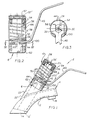
- At least two upwardly projecting cavities 54′ spaced from each other are located in retainer 54 for receipt of the prongs of a spanner wrench 80 (Figs 5 and 6). Clockwise or counterclockwise movement of retainer 54 by the spanner wrench thus applies greater or lesser compression on spring 66 to set the rate of valve closing.
- a tube cap 57 press fitted into the upper outer end of housing 58 and rotational therewith.
- This tube cap 57 is connected to hydraulic damper subassembly 56 by a nut (59) which engages the centre portion of the top surface of cap 57 and fits around and threadably engages the threaded nipple 82a protruding from the centre of hydraulic damper subassembly 56 and through cap 57.
- a dress cover 106 having spring legs 106′ is engageable with the arcuate openings 57′ in tube cape 57 to cover the mechanism.
- Hydraulic damper subassembly 56 comprises a tubular housing 82 containing an internal piston 84, a piston ring 86 and a washer 88, all retained on the inner end of the piston rod 90, the lower end of which extends through an opening 82′ in housing 82.
- the piston, ring and washer are rectilinearly movable within housing 82 along with rod 90.
- An hydraulic fluid in chamber 92 can move slowly past the position under compressive force of spring 66, from one side of the piston to the other within chamber 92.
- An annular seal 94 around the lower end of rod 90 prevents leakage of the fluid out of chamber 92.
- An annular guide 96 retains rod 90 in alignment.
- a passage 82 ⁇ having a ball type seal 98 therein, eg to allow filling.
- This passage 82 ⁇ is in protrusion 82a threaded on its exterior to receive nut 56′ (Fig 1).
- the lower extended end of rod 90 is also threaded to threadably engage within a threaded orifice in the upper end of spool valve stem 20.
- Operation of the slow close mechanism desirably enables the user to immediately select the output water temperature and flow rate with one lever, and at a valve closing rate determined only by authorised personnel and adjustable to suit the situation.
- Depressing lever 40 with a downward force allows the operator to dispense water from the faucet for the predetermined period of time. That is, when lever 40 is depressed, its canned pivot or fulcrum 42 on washer 44 provides the mechanical means necessary to lift lower guide adapter 52 and attached water faucet valve stem 20 to open position. Because both hydraulic damper subassembly 56 and compression spring 66 are attached to valve stem 20 and encapsulated by cover tube or housing 58, they are also lifted and compressed. Once compressed, the stored energy of compression spring 66 exerts force on the hydraulic damper subassembly, causing return to an extended or valve-closed state.
- the rate at which the water faucet valve closes depends upon the controlled metering of the hydraulic fluid contained in the hydraulic damper assembly and the spring rate of the compression spring.
- the speed for valve closure can be adjusted by inducing more or less compression force onto the spring. This adjustment is accomplished by removing dress cover 106, inserting the prongs 80′ of spanner wrench 80 through top arcuate access slots 57′ in cap 57 and into cavities 54′ of underlying adjusting retainer ring 54, and rotating ring 54 either clockwise or counterclockwise relative to the rest of the assembly, to increase or decrease the speed of valve closure.
- the slow close mechanism does not allow tampering with this adjustment since the appropriate spanner wrench tool must be used.
- the actuation lever also has the function of allowing the user to adjust the temperature of the water being dispensed by rotating the lever either clockwise or counterclockwise for hotter or colder water.
- a polymeric shroud 100 Between lever 40 and tube 58 in the arcuate slot 58′ is a polymeric shroud 100.
- lever 40 When lever 40 is pivoted clockwise or counterclockwise, the entire assembly pivots therewith, including shroud 100, housing 58 and mount 62.
- the actuation lever 40 translates rotational force to spool valve stem 20 by means of its engagement with lower guide adapter 52.
- Assembly of the mechanism involves placing mounting base 62 on surface 22′ of protruding valve housing 22 of the water faucet, and securing it in position by retaining clip 64. Washer 44 is then placed onto the water faucet valve stem 20. Lower guide adapter 52 is then placed onto washer 44. The hydraulic damper assembly piston rod 90 is threaded into water faucet valve stem 20 and secured against rotation with an adhesive. Compression spring 66 is placed over hydraulic damper subassembly 56 and seated onto a spring groove in lower guide adapter 52. The cover housing comprising the tube 58, the adjusting ring 54 and the tube cap 57 is then threaded onto mounting base 62. The hydraulic damper subassembly 56 is affixed to tube cap 57 by nut 56′.
Abstract
A slow closing faucet assembly (2) having hot and cold water inlets, a spool valve (6) capable of rectilinear movement for controlling water flow volume and rotational movement for controlling relative amounts of hot and cold water, a tubular housing (58) mounted on the faucet, a hydraulic damper (10) in the tubular housing having an extended piston rod (90) attached to a valve stem (20) of the spool valve, a compression coil spring (66) around the hydraulic damper between an upper retainer (54) and a lower retainer (52) the upper retainer (54) being threadably attached to the housing, and adjustable to vary the spring compression, the lower retainer being rectilinearly movable within the housing toward the upper retainer to compress the spring and hydraulic damper, and a lever (40) having an end within the housing engaged with the valve stem (20) for rotation thereof allowing water temperature control, and operable on lower retainer (52) for moving the lower retainer toward the upper retainer.
Description
- This invention relates to slow closing faucets, and more particularly to a slow closing faucet of the spool valve type. Faucets are otherwise known as taps or cocks.
- Self closing faucets have been known for some time. These are of varying construction, all closing the valve after a time delay. Prior patents disclosing such faucets are US-A specifications Nos. 557,292; 570,306; 1,063,230; 1,580,494; 2,022,791; 2,528,822; 2,829,859; 3,102,711; and 4,165,857.
- It is an object of the invention to provide a self closing, single handle faucet enabling user adjustment of the water temperature and the flow rate discharged from the faucet using the single handle, ie lever, while allowing adjustable control of the rate of closing of the faucet by only an authorised party.
- According to one aspect of the present invention a slow closing faucet assembly comprises a faucet housing, having inlets for hot and cold water and a common outlet; a spool valve in the housing the spool valve being rotational for controlling the relative flow of hot and cold water to the common outlet when said valve is rotated; the valve being reciprocable in controlled amounts between fully closed and fully open positions; the slow close mechanism comprising a housing subassembly having means for attachment to a faucet; a spring in the housing subassembly for biasing the faucet valve toward closed position; a hydraulic damper in said housing subassembly operably associated with said spring for resisting the closing action of said spring and thereby slowing the movement of said valve toward closed position; a control lever extending into the housing subassembly and having means for shifting the valve toward open position while shifting the spring against its biasing force and shifting the hydraulic damper; and adjustment means for the spring to enable the biasing force to be varied to thereby adjust the rate of movement of said valve toward the closed position.
- According to a second aspect a faucet slow close mechanism comprises a housing subassembly having means for attachment to a faucet valve toward closed position; a hydraulic damper in said housing subassembly operably associated with said spring for resisting the biasing action of said spring and thereby slowing the movement of said valve toward closed position; a control lever extending into said housing subassembly and having means for shifting said valve toward the open position while shifting said spring against its biasing force; and adjustment means for said spring to enable said biasing force to be varied to thereby adjust the rate of movement of said valve toward the closed position.
- Other aspects of the invention and preferred features are set out in the independent and dependent claims.
- The slow close mechanism constructed according to the present invention are retrofitting to an existing single handle faucet with a spool-type valve, as well as to new faucets of such type. Its structure enables easy attachment followed by dependable operation at a desired preset closing rate. A particular closing rate can be easily reset by an authorised person, yet free from tampering by unauthorised persons. A single lever controls the water temperature and water flow rate at any of several preset valve closing rates. These flow variables can be achieved without interference with or by the other variables. The resulting product may be designed to be aesthetically appealing.
- The invention may be carried into practice in various ways but one slow closing faucet will now be described by way of example with reference to the accommpanying drawings in which:
- Fig 1 is a side elevational partially sectioned view of the combination of this invention;
- Fig 2 is a sectional view of the upper portion of Fig 1;
- Fig 3 is a sectional view taken on plane III-III of Fig 2;
- Fig 4 is a sectional view of the hydraulic damper in Figs 1 & 2;
- Fig 5 is a sectional view comparable to Fig 2 except including a special adjustment spanner wrench; and
- Fig 6 is a top plan view of the subject matter of Fig 5.
- Referring now specifically to the drawings, the
complete assembly 2 there depicted includes a spigot subassembly 4, amixing valve subassembly 6, avalve actuator subassembly 8 and a slow close subsumable 10. - Spigot subassembly 4 is of generally conventional construction, including an upwardly outwardly projecting faucet or
spigot 12 having abase 14 for mounting it on a sink. Such spigot is hollow, including awater outlet 16 on the bottom of the upper outer end, and conventional hot and cold inlets at the base, leading to the hollow interior orconduit 12′ which forms a passageway. Projecting upwardly from the faucet and forming an integral part thereof is a hollow valve support orprotrusion 22 having a flat annularouter surface 22′. Theinner chamber 22˝ ofprotrusion 22 is in alignment with and communicates directly with the lower portion ofconduit 12′ infaucet 12.Mixing valve subassembly 6 is located within thischamber 22˝, extending down into theconduit 12′ and projecting at its upper end fromchamber 22˝ and beyondflat surface 22′ as indicated in Fig 1. This mixing valve subassembly is a spool valve type as set forth in US-A-4,495,969 or an equivalent spool valve.Subassembly 6 includes avalve stem 20 having ashaft portion 32 projecting upwardly from the main body of the valve, this shaft portion having a pair of flats 34 (Fig 3) on opposite sides thereof. (See such components in said US-A-4,495,969.) Rotation of this valve stem about its longitudinal axis causes the valve to allow controlled amounts of hot water and of cold water to enter and mix together inchamber 12′, and flow tooutlet 16. Reciprocation, ie rectilinear movement of the valve stem, causes the volume of water flow throughchamber 12′ to be varied. The user of the faucet directly governs these two variables using a single lever. -
Valve actuator subassembly 8 includes anactuator lever 40 capable of rotatingvalve stem 20 and of shifting it rectilinearly, as will be described more fully hereinafter. Near the lower end oflever 40, is a pivot fulcrum offset orapex 42 which engages the upper surface of an annular fulcrum washer 44 just beneath the inner end oflever 40. The inner end oflever 40, as well aswasher 44 and the upper protruding end ofmixing valve subassembly 6 are all located within a cylindrical tubular housing orcover tube 58. This housing has internal threads at its lower end, threadably engaged onto acylindrical mounting base 62. The lower end ofmounting base 62 abutsflat surface 22′ on the faucet projection, said base also surrounding the housing of mixing valve subassembly 6 (Fig 1).Mounting base 62 is secured againstprotrusion 22 by anannular retaining clip 64 which lies in the top ofbase 62 and has an inner annular surface which engages the housing of mixing valve subassembly 6. This annular clip bites into the periphery of the valve housing to secure the base and the members mounted thereabove to the faucet.Washer 44 rests on the outer annular end ofvalve subassembly 6, having a central opening to receivevalve stem 20 therethrough. Resting onwasher 44 is alower guide adapter 52 which has a smaller diameter lower neck and a larger diameter upper head. This head is secured betweenpiston rods 90 andvalve stem 20 to move rectilinearly therewith. The inner end oflever 40 is of forked construction, the bifurcated legs thereof protruding around the valve stem and engaging a pair of external flats on the neck of lower guide adapter orretainer 52 so that, whenlever 40 is pivoted about the central axis of the valve stem,adapter 52 will also pivot therewith. This adapter has a central opening with internal flats matching those ofouter flats 34 onvalve stem 20 so that rotation ofadapter 52 causes rotation ofvalve stem 20. Thus, the lower end oflever 40 is between underlyingwasher 44 andoverlying guide adapter 52. This guide adapter also comprises a lower retainer for acompression coil spring 66 which has its lower end in engagement withretainer 52 and its upper end in engagement with upperadjustable retainer ring 54. Upper end in engagement with upperadjustable retainer ring 54.Upper retainer 54 is an annular member having threads on its outer peiphery in threaded engagement with corresponding threads on the inner surface of the upper end oftubular housing 58. At least two upwardly projectingcavities 54′ spaced from each other are located inretainer 54 for receipt of the prongs of a spanner wrench 80 (Figs 5 and 6). Clockwise or counterclockwise movement ofretainer 54 by the spanner wrench thus applies greater or lesser compression onspring 66 to set the rate of valve closing. Immediately aboveretainer 54 is atube cap 57 press fitted into the upper outer end ofhousing 58 and rotational therewith. Thistube cap 57 is connected tohydraulic damper subassembly 56 by a nut (59) which engages the centre portion of the top surface ofcap 57 and fits around and threadably engages the threaded nipple 82a protruding from the centre ofhydraulic damper subassembly 56 and throughcap 57. Adress cover 106 havingspring legs 106′ is engageable with thearcuate openings 57′ intube cape 57 to cover the mechanism. -
Hydraulic damper subassembly 56 comprises atubular housing 82 containing aninternal piston 84, apiston ring 86 and awasher 88, all retained on the inner end of thepiston rod 90, the lower end of which extends through an opening 82′ inhousing 82. The piston, ring and washer are rectilinearly movable withinhousing 82 along withrod 90. An hydraulic fluid inchamber 92 can move slowly past the position under compressive force ofspring 66, from one side of the piston to the other withinchamber 92. Anannular seal 94 around the lower end ofrod 90 prevents leakage of the fluid out ofchamber 92. Anannular guide 96 retainsrod 90 in alignment. At the opposite, ie upper, end of the housing from which the rod extends is apassage 82˝ having aball type seal 98 therein, eg to allow filling. Thispassage 82˝ is in protrusion 82a threaded on its exterior to receivenut 56′ (Fig 1). The lower extended end ofrod 90 is also threaded to threadably engage within a threaded orifice in the upper end ofspool valve stem 20. - Operation of the slow close mechanism desirably enables the user to immediately select the output water temperature and flow rate with one lever, and at a valve closing rate determined only by authorised personnel and adjustable to suit the situation.
-
Depressing lever 40 with a downward force allows the operator to dispense water from the faucet for the predetermined period of time. That is, whenlever 40 is depressed, its canned pivot orfulcrum 42 onwasher 44 provides the mechanical means necessary to liftlower guide adapter 52 and attached water faucet valve stem 20 to open position. Because bothhydraulic damper subassembly 56 andcompression spring 66 are attached tovalve stem 20 and encapsulated by cover tube orhousing 58, they are also lifted and compressed. Once compressed, the stored energy ofcompression spring 66 exerts force on the hydraulic damper subassembly, causing return to an extended or valve-closed state. The rate at which the water faucet valve closes depends upon the controlled metering of the hydraulic fluid contained in the hydraulic damper assembly and the spring rate of the compression spring. Thus, for a given hydraulic damper assembly, the speed for valve closure can be adjusted by inducing more or less compression force onto the spring. This adjustment is accomplished by removingdress cover 106, inserting theprongs 80′ ofspanner wrench 80 through toparcuate access slots 57′ incap 57 and intocavities 54′ of underlying adjustingretainer ring 54, and rotatingring 54 either clockwise or counterclockwise relative to the rest of the assembly, to increase or decrease the speed of valve closure. The slow close mechanism does not allow tampering with this adjustment since the appropriate spanner wrench tool must be used. - The actuation lever also has the function of allowing the user to adjust the temperature of the water being dispensed by rotating the lever either clockwise or counterclockwise for hotter or colder water. Between
lever 40 andtube 58 in thearcuate slot 58′ is apolymeric shroud 100. Whenlever 40 is pivoted clockwise or counterclockwise, the entire assembly pivots therewith, includingshroud 100,housing 58 andmount 62. Theactuation lever 40 translates rotational force to spool valve stem 20 by means of its engagement withlower guide adapter 52. - Assembly of the mechanism involves placing mounting
base 62 onsurface 22′ of protrudingvalve housing 22 of the water faucet, and securing it in position by retainingclip 64.Washer 44 is then placed onto the waterfaucet valve stem 20.Lower guide adapter 52 is then placed ontowasher 44. The hydraulic damperassembly piston rod 90 is threaded into waterfaucet valve stem 20 and secured against rotation with an adhesive.Compression spring 66 is placed overhydraulic damper subassembly 56 and seated onto a spring groove inlower guide adapter 52. The cover housing comprising thetube 58, the adjustingring 54 and thetube cap 57 is then threaded onto mountingbase 62. Thehydraulic damper subassembly 56 is affixed totube cap 57 bynut 56′. The bifurcated side slot incover tube 58 and engaged ontolower guide adapter 52. Alever shroud 100 aroundlever 40 is then pressed into the covertube entry slot 58′. The spring loadedprongs 106′ of the dress cover are pressed intoslots 57′ provided in the top of the tube cap for final assembly.
Claims (17)
1. A faucet and faucet slow close mechanism comprising a faucet housing having inlets for hot and cold water and a common outlet (16); a spool valve (6) in housing, the spool valve being rotational for controlling the relative flow of hot and cold water to the common outlet when said valve is rotated; the valve being reciprocable in controlled amounts between fully closed and fully open positions; the slow close mechanism (10) comprising a housing subassembly having means for attachment to a faucet; a spring (66) in the housing subassembly for biasing the faucet valve toward closed position; a hydraulic damper (56) in said housing subassembly operably associated with said spring for resisting the closing action of said spring and thereby slowing the movement of said valve toward closed position; a control lever (40) extending into the housing subassembly and having means for shifting the valve toward open position while shifting the spring against its biasing force and shifting the hydraulic damper and; adjustment means (54) for the spring to enable the biasing force to be varied to thereby adjust the rate of movement of said valve toward the closed position.
2. A faucet slow close mechanism according to claim 1 wherein said spring is a compression spring trapped at its ends by a pair of retainers (52,54) one of the retainers (54) being adjustably movable to vary the distance between the retainers and thereby the length and compression of said spring.
3. A faucet slow close mechanism according to claim 1 and claim 2 wherein the spring extends around the hydraulic damper (56).
4. A faucet slow close mechanism according to any of claims 1 to 3 wherein said one retainer (54) is at the end of the spring (66) furthest from the lever (40) and the other retainer (52) is on the end of said spring closest to said lever.
5. A slow closing faucet assembly (2) comprising: a faucet having hot and cold water inlets and an outlet; the faucet including a valve-receiving protrusion (22); a spool valve subassembly (6) in the faucet protrusion, capable of rectilinear movement for controlling the water flow volume through the faucet and capable of rotational movement for controlling the relative amounts of hot and cold water into the faucet; the spool valve having a valve stem (20) extending therefrom and from the protrusion; a tubular housing subassembly (10) attached to the protrusion, having a mounting base (62) at its lower end on the protrusion, and a tube cap at its upper end; a hydraulic damper (56) in the tubular housing, including an inner piston (84) an extending piston rod (90) and hydraulic fluid movable from one side of the piston to the other under a biasing force; the hydraulic damper (56) being secured by the tube cap (57) and having its extended piston rod (90) attached to the valve stem (20); a compression coil spring (66) around the hydraulic damper, in the tubular housing, extending between an upper retainer (54) and a lower retainer (52); the upper retainer (54) being threadably attached to the housing (58); the lower retainer being rectilinearly movable within the housing toward the upper retainer to compress the spring and the hydraulic damper; a lever (40) having an end within the housing, the lever being engaged with the valve stem for rotation thereof allowing water temperature control, and operable on the lower retainer for moving the lower retainer (52) toward the upper retainer (54) for water flow rate control with the lever; the upper retainer (54) being rotationally adjustable to move it axially and thereby control compression of the spring (56); and the tube cap (57) having opening (57) therein allowing access to the upper retainer for adjustment.
6. A slow closing faucet assembly according to claim 5 which includes spanner wrench cavities (54′) in the upper retainer (54), and arcuate slots (57′) in the tube cap aligned with the cavities for insertion of spanner wrench prongs through the slots into the cavities for the said adjustment of the upper retainer.
7. A slow closing faucet assembly (2) comprising: a faucet a valve receiving protrusion (22); a spool valve subassembly in the faucet protrusion (22), capable of rectilinear movement for controlling water flow volume through the faucet and capable of rotational movement for controlling relative amounts of hot and cold water into the faucet; the spool valve having a valve stem (20) extending therefrom and from the protrusion; a tubular housing subassembly (10) attached to the protrusion (22) by a mounting base (62) at its lower end on the protrusion (22); a hydraulic damper (56) in the tubular housing, including an inner piston (84) and extending piston rod (90), and hydraulic fluid movable from one side of the piston to the other under a biasing force; the hydraulic damper having its extended piston rod attached to the valve stem (20); a spring (66) in the tubular housing extending between an upper retainer (54) and a lower retainer (52); the lower retainer being rectilinearly movable within the housing relative to said upper retainer to bias the spring and shift the hydraulic damper; a lever having an end within the housing, said lever being engaged with the valve stem (20) for rotation thereof allowing water temperature control, and operable on the lower retainer (52) for moving the lower retainer relative to the upper retainer (54) for water flow rate control; and the upper retainer (54) being adjustably movable relative to the housing (58) to vary the bias on the spring and thereby alter the rate of spool valve closing.
8. A slow closing faucet according to claim 7 including spanner wrench prong-receiving cavities (57′) in the upper retainer (54) for adjusting movement thereof by a spanner wrench (80).
9. A slow closing faucet assembly according to claim 7 including a cap (57) on the housing adjacent the upper retainer (54); the cap includes arcuate slots (57) aligned with the said cavities (54) for allowing access to the cavities through said cap by prongs (80) of a spanner wrench (80).
10. A slow closing faucet assembly to claim 9 including a dress cover (106) on the housing and over the cap (57) the dress cover having connector means (106′) for removably securing it to said housing.
11. A slow closing faucet assembly according to claim 10 wherein the connector means comprises spring legs (106′) engageable with said arcuate slots (57′).
12. A faucet slow close mechanism comprising a housing subassembly having means for attachment to a faucet, said faucet having a linearly movable valve for controlling flow therepast; a spring (66) in said housing subassembly for biasing said faucet valve toward closed position; a hydraulic damper (56) in said housing subassembly operably associated with said spring for resisting the biasing action of said spring and thereby slowing the movement of said valve toward closed position; a control lever (40) extending into said housing subassembly and having means for shifting said valve toward the open position while shifting said spring against its biasing force; and adjustment means (54) for said spring to enable said biasing force to be varied to thereby adjust the rate of movement of said valve toward the closed position.
13. A faucet slow close mechanism according to claim 12 wherein said spring is a compression spring trapped at its ends by a pair of retainers, one of said retainers (54) being movable to vary the distance between said retainers and thereby the length and compression of said spring.
14. A faucet slow close mechanism according to claim 12 or claim 13 wherein said spring extends around said hydraulic damper.
15. A slow closing attachment for a faucet assembly having hot and cold water inlets, a common outlet, and a spool valve which is rotational for controlling outlet water temperature and is reciprocable for controlling output flow rate, comprising: a tubular housing having a mounting base at its lower end for attachment to the faucet; a hydraulic damper in said tubular housing, including an inner piston, an extending piston rod, and hydraulic fluid movable from one side of said piston to the other under a biasing force; said hydraulic damper having its extended piston rod attached to said valve stem; a spring in said tubular housing, extending between an upper retainer and a lower retainer; said lower retainer being rectilinearly movable within said housing relative to said upper retainer to bias said spring and shift said hydraulic damper; a lever having an end within said housing, said lever being engaged with said valve stem for rotation thereof allowing water temperature control, and operable on said lower retainer for moving said lower retainer relative to said upper retainer for water flow rate control; and said upper retainer being adjustably movable relative to said housing to vary the bias on said spring and thereby alter the rate of spool valve closing.
16. A slow closing faucet assembly according to claim 15 including spanner wrench prong-receiving cavities in said upper retainer for adjusting movement thereof by a spanner wrench.
17. An attachable slow close subassembly for attachment to a faucet having a valve which is rotational to control output water temperature, and rectilinearly movable to control output water flow rate, said subassembly comprising: a mounting base; a coil spring in said housing; a pair of spring retainers at the ends of said coil spring including a lower retainer adjacent said slave and an upper retainer; an actuation lever extending into said housing adjacent said lower retainer and engaging said valve stem, said lever being movable in an arc for rotating said valve stem and thereby controlling the relative inlet of hot and cold water; said lever also being pivotally rockable to shift said valve stem rectilinearly to adjust the flow rate of water through said mechanism; said upper spring retainer being an annulus around said hydraulic damper and threadably engaged with said housing; and means on said annulus for engagement by a tool for adjusting the distance between retainers and thereby the amount of compression on said coil spring for controlling the rate of return of said valve toward the closed position.
Applications Claiming Priority (2)
| Application Number | Priority Date | Filing Date | Title |
|---|---|---|---|
| US421778 | 1989-10-16 | ||
| US07/421,778 US4936347A (en) | 1989-10-16 | 1989-10-16 | Faucet actuator |
Publications (1)
| Publication Number | Publication Date |
|---|---|
| EP0424101A1 true EP0424101A1 (en) | 1991-04-24 |
Family
ID=23672007
Family Applications (1)
| Application Number | Title | Priority Date | Filing Date |
|---|---|---|---|
| EP90311334A Ceased EP0424101A1 (en) | 1989-10-16 | 1990-10-16 | Faucet actuator |
Country Status (3)
| Country | Link |
|---|---|
| US (1) | US4936347A (en) |
| EP (1) | EP0424101A1 (en) |
| CA (1) | CA2018422A1 (en) |
Families Citing this family (12)
| Publication number | Priority date | Publication date | Assignee | Title |
|---|---|---|---|---|
| DE4004700A1 (en) * | 1990-02-15 | 1991-08-22 | Ideal Standard | LOCKING DAMPER FOR A SANITARY WATER FITTING |
| SE9101852A0 (en) * | 1991-06-17 | 1992-12-18 | Gustavsberg Vårgårda Armatur Ab | Mixer valve of single lever type provided with device for preventing pressure shock during closing of the lever |
| DE4416640A1 (en) * | 1994-05-11 | 1995-11-16 | A I D Autoimmun Diagnostika Gm | Carrier for microscopy is multi-well plate with thin base to wells |
| MXPA03001211A (en) * | 2003-02-07 | 2004-08-11 | Felix Duran Carlos | Deviation valve with adjustable time and momentary closure. |
| US7458520B2 (en) * | 2005-04-19 | 2008-12-02 | Masco Corporation Of Indiana | Electronic proportioning valve |
| US7475827B2 (en) | 2005-04-19 | 2009-01-13 | Masco Corporation Of Indiana | Fluid mixer |
| US7448553B2 (en) | 2005-04-19 | 2008-11-11 | Masco Corporation Of Indiana | Fluid mixer |
| US7584898B2 (en) | 2005-07-01 | 2009-09-08 | Masco Corporation Of Indiana | Manual override for electronic proportioning valve |
| US8109293B2 (en) * | 2007-01-31 | 2012-02-07 | Moen Incorporated | Valve cartridge with isolated friction and cartridge loads |
| CN105115159B (en) * | 2015-08-25 | 2017-10-13 | 王全伟 | A kind of piston type water tank |
| US11287053B1 (en) * | 2020-09-23 | 2022-03-29 | Kuching International Ltd. | Pressing-controlled mixing valve core with through flow control type on the top |
| EP4043764A1 (en) * | 2021-02-10 | 2022-08-17 | B/E Aerospace, Inc. | Self closing taps |
Citations (8)
| Publication number | Priority date | Publication date | Assignee | Title |
|---|---|---|---|---|
| US557292A (en) * | 1896-03-31 | William a | ||
| US859371A (en) * | 1906-07-02 | 1907-07-09 | Mark F Coyle | Slow-closing valve. |
| US1063230A (en) * | 1911-08-28 | 1913-06-03 | Earl G Watrous | Basin-cock. |
| US1580494A (en) * | 1925-01-03 | 1926-04-13 | William L Jones | Flushing valve |
| US2022791A (en) * | 1929-09-20 | 1935-12-03 | Lewis J Tetlow | Valve |
| US2829859A (en) * | 1954-08-06 | 1958-04-08 | Fred J Morris Company Inc | Manually reset time-controlled valve |
| US3102711A (en) * | 1959-10-08 | 1963-09-03 | Sloan Valve Co | Flush valves |
| US4723574A (en) * | 1985-06-29 | 1988-02-09 | American Standard Inc. | Sanitary water fitting |
Family Cites Families (6)
| Publication number | Priority date | Publication date | Assignee | Title |
|---|---|---|---|---|
| US570306A (en) * | 1896-10-27 | William a | ||
| US2528822A (en) * | 1947-06-20 | 1950-11-07 | Ernest A Dunn | Automatic shutoff valve |
| US2557287A (en) * | 1949-04-01 | 1951-06-19 | Scovill Manufacturing Co | Device for controlling time duration for operation of a valve |
| US2963259A (en) * | 1957-09-09 | 1960-12-06 | William T Heyer | Metering valve |
| US4165857A (en) * | 1976-03-18 | 1979-08-28 | Acorn Engineering Co. | Dashpot mechanism for self-closing plumbing valves |
| US4495969A (en) * | 1981-11-23 | 1985-01-29 | Stanadyne, Inc. | Mixing valve with water modulation sealing means |
-
1989
- 1989-10-16 US US07/421,778 patent/US4936347A/en not_active Expired - Fee Related
-
1990
- 1990-06-06 CA CA002018422A patent/CA2018422A1/en not_active Abandoned
- 1990-10-16 EP EP90311334A patent/EP0424101A1/en not_active Ceased
Patent Citations (8)
| Publication number | Priority date | Publication date | Assignee | Title |
|---|---|---|---|---|
| US557292A (en) * | 1896-03-31 | William a | ||
| US859371A (en) * | 1906-07-02 | 1907-07-09 | Mark F Coyle | Slow-closing valve. |
| US1063230A (en) * | 1911-08-28 | 1913-06-03 | Earl G Watrous | Basin-cock. |
| US1580494A (en) * | 1925-01-03 | 1926-04-13 | William L Jones | Flushing valve |
| US2022791A (en) * | 1929-09-20 | 1935-12-03 | Lewis J Tetlow | Valve |
| US2829859A (en) * | 1954-08-06 | 1958-04-08 | Fred J Morris Company Inc | Manually reset time-controlled valve |
| US3102711A (en) * | 1959-10-08 | 1963-09-03 | Sloan Valve Co | Flush valves |
| US4723574A (en) * | 1985-06-29 | 1988-02-09 | American Standard Inc. | Sanitary water fitting |
Also Published As
| Publication number | Publication date |
|---|---|
| CA2018422A1 (en) | 1991-04-16 |
| US4936347A (en) | 1990-06-26 |
Similar Documents
| Publication | Publication Date | Title |
|---|---|---|
| US4936347A (en) | Faucet actuator | |
| US5358213A (en) | Faucet having automatic and manual control capability | |
| US4116216A (en) | Remotely actuated valves and fluid distribution system including same | |
| US8555922B2 (en) | Metering mixing faucet | |
| KR930001579B1 (en) | Self-closing valve for sanitary installations | |
| EP2865928B1 (en) | Valve | |
| US20060202138A1 (en) | Level-handled type automatic shutoff faucet structure | |
| US7134451B1 (en) | Metering faucet assembly including temperature control | |
| US20040134939A1 (en) | Device and method for connecting a pressure source to a container | |
| US20100171053A1 (en) | Tap adaptors | |
| US3342451A (en) | Valve | |
| IL32819A (en) | Icecream dispenser | |
| US4568060A (en) | Shower installation and valve therefore | |
| GB2067516A (en) | Liquid or powder dispenser | |
| US4361168A (en) | Flush valve construction | |
| GB2157811A (en) | Ablution faucet | |
| US4308978A (en) | Dispensing device | |
| US4520992A (en) | Slow-closing valve mechanism | |
| US6634395B1 (en) | Double poppet valve for precise shut off of fuel dispensing nozzle | |
| US1218567A (en) | Automatic valve device for distributing liquid under pressure. | |
| GB2126691A (en) | Closure valve | |
| US3251507A (en) | Dispensing nozzle with pre-set shut-off | |
| US4572411A (en) | Valve assembly for a dispensing head | |
| US3419036A (en) | Valve assembly | |
| US1281566A (en) | Self-closing flush-valve. |
Legal Events
| Date | Code | Title | Description |
|---|---|---|---|
| PUAI | Public reference made under article 153(3) epc to a published international application that has entered the european phase |
Free format text: ORIGINAL CODE: 0009012 |
|
| AK | Designated contracting states |
Kind code of ref document: A1 Designated state(s): AT BE CH DE DK ES FR GB GR IT LI LU NL SE |
|
| 17P | Request for examination filed |
Effective date: 19911011 |
|
| 17Q | First examination report despatched |
Effective date: 19930402 |
|
| STAA | Information on the status of an ep patent application or granted ep patent |
Free format text: STATUS: THE APPLICATION HAS BEEN REFUSED |
|
| 18R | Application refused |
Effective date: 19940729 |