EP0423403A1 - Solid-liquid separator and process for washing the same - Google Patents
Solid-liquid separator and process for washing the same Download PDFInfo
- Publication number
- EP0423403A1 EP0423403A1 EP89310674A EP89310674A EP0423403A1 EP 0423403 A1 EP0423403 A1 EP 0423403A1 EP 89310674 A EP89310674 A EP 89310674A EP 89310674 A EP89310674 A EP 89310674A EP 0423403 A1 EP0423403 A1 EP 0423403A1
- Authority
- EP
- European Patent Office
- Prior art keywords
- filter medium
- packed
- washing
- tank
- zone
- Prior art date
- Legal status (The legal status is an assumption and is not a legal conclusion. Google has not performed a legal analysis and makes no representation as to the accuracy of the status listed.)
- Withdrawn
Links
Images
Classifications
-
- B—PERFORMING OPERATIONS; TRANSPORTING
- B01—PHYSICAL OR CHEMICAL PROCESSES OR APPARATUS IN GENERAL
- B01D—SEPARATION
- B01D24/00—Filters comprising loose filtering material, i.e. filtering material without any binder between the individual particles or fibres thereof
- B01D24/02—Filters comprising loose filtering material, i.e. filtering material without any binder between the individual particles or fibres thereof with the filter bed stationary during the filtration
- B01D24/20—Filters comprising loose filtering material, i.e. filtering material without any binder between the individual particles or fibres thereof with the filter bed stationary during the filtration the filtering material being provided in an open container
- B01D24/26—Upward filtration
- B01D24/263—Upward filtration the filtering material being supported by pervious surfaces
-
- B—PERFORMING OPERATIONS; TRANSPORTING
- B01—PHYSICAL OR CHEMICAL PROCESSES OR APPARATUS IN GENERAL
- B01D—SEPARATION
- B01D24/00—Filters comprising loose filtering material, i.e. filtering material without any binder between the individual particles or fibres thereof
- B01D24/46—Regenerating the filtering material in the filter
- B01D24/4631—Counter-current flushing, e.g. by air
-
- B—PERFORMING OPERATIONS; TRANSPORTING
- B01—PHYSICAL OR CHEMICAL PROCESSES OR APPARATUS IN GENERAL
- B01D—SEPARATION
- B01D24/00—Filters comprising loose filtering material, i.e. filtering material without any binder between the individual particles or fibres thereof
- B01D24/46—Regenerating the filtering material in the filter
- B01D24/4668—Regenerating the filtering material in the filter by moving the filtering element
- B01D24/4684—Regenerating the filtering material in the filter by moving the filtering element using spray devices
-
- B—PERFORMING OPERATIONS; TRANSPORTING
- B01—PHYSICAL OR CHEMICAL PROCESSES OR APPARATUS IN GENERAL
- B01D—SEPARATION
- B01D2201/00—Details relating to filtering apparatus
- B01D2201/14—Particulate filter materials with a lower density than the liquid mixture to be filtered
Definitions
- This invention relates to a solid-liquid separator for use in a primary treatment of waste water containing solid matter, and to a process for washing the solid-liquid separator.
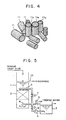
- FIG. 5 A method of washing a downward flow type filter according to the prior art, based mainly on sand filtration, is shown in Fig. 5.
- the system shown in the figure comprises a tank 1 packed with a layer of sand 2, a washing water tank 3, a washing pump 4, a surface washing water pipe 5, a backwash pipe 6, control valves 7 to 9, and a backwash drain pipe 10.
- the washing pump 4 is operated and the control valves 7 to 9 are controlled, whereby washing water is first pumped up from the washing water tank 3 and is sprinkled through the surface washing water pipe 5 to wash the surface of the sand layer 2 (surface washing). Then, the washing water in the tank 3 is fed under high pressure through the back washing pipe 6, which serves also as a treated water pipe, into a lower portion of the sand layer 2, thereby washing the entire part of the sand layer 2 (back washing). In this step, the sand layer 2 is expanded, and the suspended solids (SS) caught in space portions in the sand layer 2 are removed from the space portions, to be discharged through the backwash drain pipe 10. In some cases, air washing is also used, prior to the washing with water.
- SS suspended solids
- the conventional method of washing a sand filter requires huge expenses for operation and maintenance, because the method uses a large amount of washing water for surface washing and back washing.
- the method requires additional equipment such as the washing water tank, washing pump, etc., leading to a high equipment cost as well as a problem on a spatial basis.
- the capture of the suspended solids (SS) takes place concentratedly in the vicinity of the surface of the sand layer, and the SS are practically caught in voids between the grains of sand. Therefore, the above-mentioned washing with water is enough to remove the SS from the sand filter.
- a filter medium 11 which is used in a solid-liquid separator according to the present assignee's prior application [for instance, Japanese Patent Application Laid-Open (KOKAI) No. 63-32861(1988)].
- a filter medium namely, a small cylindrical plastic filter medium having a specified gravity of not more than 1.0 and a void ratio of at least 70%, suspended solids are not only caught in the voids between the pieces of filter medium 11 but are caught, in considerable amounts, in space portions 11a constituting the interior of the cylindical pieces of filter medium 11.
- the SS are not only caught on the surface of the packed bed but are caught in a high density throughout the range of the packed bed (for instance, 1.5 to 2 m deep). ln this case, therefore, it is impossible to achieve satisfactory removal of the SS from the space portions 11a of the filter medium 11 by the above-mentioned water washing.
- This invention contemplates overcoming the above-mentioned problems.
- the entire part of a filter medium in a tank is maintained in a fluidized state by air washing. Then, with the fluidized state maintained, a liquid in the tank is rapidly drained through a lower portion of the tank until part or the entire part of the filter medium is exposed above the surface of the liquid.
- the solid-liquid separator according to this invention comprises a bed packed with a buoyant filter medium having a specific gravity of not more than 1.0, wherein a required amount of the filter medium is so packes as to provide a non-packed zone between the lower end of the filter medium packed bed and a filter medium support plate disposed on the lower side of the filter medium packed bed, during a filtering step, and an air introducing pipe for backwash is disposed on the lower side of the filter medium support plate.
- the filter medium is preferably so packed that the space ratio of the filter medium packed zone to the non-packed zone is in the range of from 1:1 to 1:6, as described in claim 6 of the appended claims.
- FIG. 1 This embodiment illustrates a solid-liquid separator, shown in Fig. 1.
- a tank 12 is provided with a filter medium packed bed 13, a sedimentation zone 15 and the like.
- a required amount of a filter medium 11, shown in Fig. 4 is packed in the filter medium packed bed 13 between a top retainer plate 22 and a filter medium support plate 14.
- the filter medium 11 occupies only part of the region in the filter medium packed bed 13 so that the pieces of filter medium 11 are capable of moving within the packed bed 13, as will be described later.
- the zone in which the pieces of filter medium 11 are packed in a cluster-like condition will be hereinafter referred to as "the filter medium packed zone 13a".
- the top retainer plate 22 prevents the filter medium from flowing out through floating up.
- a sedimentation zone 15 is provided on the lower side of the filter medium support plate 14.
- An inlet pipe 16 is provided for feeding influent water into the sedimentation zone 15 by operating a pump P.
- An outlet pipe 17 is provided for discharge the treated water via an upper portion of the tank 12.
- An air introducing pipe 18 is provided for introducing air into the sedimentation zone 15 below the filter medium support plate 14 by operating a blower 8.
- a drain pipe 19 is provided with a drain valve 20 or a drain pump (not shown), for draining a liquid in the tank 12 via a lower portion of the tank.
- a non packed zone 21 is formed between the lower end of the filter medium packed zone 13a and the filter medium support plate 14, during a filtering step for the influent water.
- the required amount of the filter medium 11 is packed in the packed bed 13 so that the ratio of the volume A of the non-packed zone 21 to the volume B of the filter medium packed zone 13a is in the range of from 1:1 to 1:6.
- the upward flow type solid-liquid separator operates as follows.
- Fig. 1 shows the filtering step, in which the pump P is operated, whereby the influent water, or waste water containing solid matter, is fed into the sedimentation zone 15 via the inlet pipe 16.
- the influent water, or waste water containing solid matter is fed into the sedimentation zone 15 via the inlet pipe 16.
- those having a relatively high specific gravity are sedimented in the sedimentation zone 15.
- the influent water containing those solids having a lower specific gravity then flows upward through the filter medium packed bed 13, while the solids are caught in not only the voids between the pieces of filter medium 11 but the space portions 11a in the filter medium 11.
- the second solid-liquid separation takes place.
- the thus treated water is discharged through the outlet pipe 17.
- the filter medium 11 has a very low specific gravity of not more than 1.0, with an extremely high void ratio of at least 70%.
- the packing of the filter medium 11 in the packed bed 13 is so set that the ratio of the volume A of the non packed zone 21 to the volume B of the packed zone 13a is in the range of from 1:1 to 1:6. Therefore, the filter medium 11 is floated up by the upward flow of the influent water to form a fixed bed beneath the top retainer plate 22, and the non-packed zone 21 is formed on the lower side of the fixed bed. Then, the SS are not only caught in the voids between the pieces of filter medium 11 but are trapped in a high concentration in the space portions 11a (See Fig. 4) in the filter medium 11.
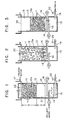
- Figs. 2 and 3 each show the washing step.
- the blower B is operated to introduce air through the air introducing pipe 18 into the sedimentation zone 15, to perform air washing (air washing step).
- the air washing causes the buoyant filter medium 11 having the specific gravity of 1.0 or below to be agitated sufficiently in the filter medium packed bed 13 including the non packed zone 21 between the filter medium support plate 14 and the top retainer plate 22. Therefore, the filter medium 11 is brought into a satisfactorily fluidized state, and is circulated between the retainer plate 22 and the support plate 14.
- the air introduced into the sedimentation zone 15 flows upward through the filter medium support plate 14, whereby washing of the support plate 14 is achieved simultaneously with the above-mentioned washing of the filter medium 11. Therefore, the filter medium support plate 14 is prevented from being clogged.
- the drain valve 20 is opened or the drain pump (not shown) is operated, whereby the mixed water (tank liquid) in which the SS are suspended throughout the tank 12 is rapidly drained through the drain pipe 19 provided at the lower portion of the tank 12.
- the SS are also rapidly discharged together with the mixed water via the lower porition of the tank 12 (draining step).
- the mixed water should be drained at a considerably high velocity in order to prevent the SS suspended in the mixed water from being caught again into the space portions 11a in the filter medium 11.
- a drain velocity of at least about 0.3 m/min should be employed.
- the rapid draining of the mixed water should be continued until the water level is lowered to or below the filter medium support plate 14 and the entire body of the filter medium 11 is completely exposed above the water surface.
- this invention is applicable to any process for washing a solid-liquid separator which uses one of a variety of filter media formed of a plastic, polyethylene, polypropylene or the like having a specific gravity of not more than 1.0
- the rapid draining of the tank liquid via the lower portion of the tank according to this invention ensures that the SS in the above-mentioned suspended state are rapidly removed without being again caught into the space portions in the filter medium.
- the void ratio of the filter medium is at least 70%, whereby it is possible to catch effectively the SS contained in the influent water.
- the amount of the filter medium packed in the tank is so set that the space ratio of the non-packed zone to the filter medium packed zone is in the range of from 1:1 to 1:6, according to the invention. This setting ensures sufficient agitation of the filter medium in the tank, and effective washing of the filter medium.
- the filter medium at the time of washing the filter medium by air washing, it is possible to agitate sufficiently the entire body of the filter medium into a satisfactorily fluidized state. This ensures that not only the SS caught in the voids between the pieces of filter medium but the SS trapped in the space portion of the filter medium are capable of being brought into the suspended state.
- the tank liquid is rapidly drained through a lower portion of the tank. Therefore, it is possible to wash the filter medium effectively and to remove the SS satisfactorily.
- prevention of the clogging of the filter medium support plate is achieved simultaneously with the washing of the filter medium, by air washing. This ensures easy maintenance.
Abstract
A solid-liquid separator and a process for washing the same wherein SS (suspended solids) caught in space portions of a filter medium in a tank are caused to flow out from the space portions and be suspended while at least part of the filter medium is maintained in a fluidized state by air washing, and rapid drainage through a iower portion of the tank causes the SS in the suspended state to be rapidly removed without being again caught into the space portions of the filter medium.
Description
- This invention relates to a solid-liquid separator for use in a primary treatment of waste water containing solid matter, and to a process for washing the solid-liquid separator.
- A method of washing a downward flow type filter according to the prior art, based mainly on sand filtration, is shown in Fig. 5. The system shown in the figure comprises a
tank 1 packed with a layer ofsand 2, awashing water tank 3, awashing pump 4, a surfacewashing water pipe 5, abackwash pipe 6,control valves 7 to 9, and abackwash drain pipe 10. - In washing the filter, the
washing pump 4 is operated and thecontrol valves 7 to 9 are controlled, whereby washing water is first pumped up from thewashing water tank 3 and is sprinkled through the surfacewashing water pipe 5 to wash the surface of the sand layer 2 (surface washing). Then, the washing water in thetank 3 is fed under high pressure through theback washing pipe 6, which serves also as a treated water pipe, into a lower portion of thesand layer 2, thereby washing the entire part of the sand layer 2 (back washing). In this step, thesand layer 2 is expanded, and the suspended solids (SS) caught in space portions in thesand layer 2 are removed from the space portions, to be discharged through thebackwash drain pipe 10. In some cases, air washing is also used, prior to the washing with water. - The conventional method of washing a sand filter requires huge expenses for operation and maintenance, because the method uses a large amount of washing water for surface washing and back washing. In addition, the method requires additional equipment such as the washing water tank, washing pump, etc., leading to a high equipment cost as well as a problem on a spatial basis.
- Meanwhile, in the sand filter, the capture of the suspended solids (SS) takes place concentratedly in the vicinity of the surface of the sand layer, and the SS are practically caught in voids between the grains of sand. Therefore, the above-mentioned washing with water is enough to remove the SS from the sand filter.
- Referring to Fig. 4, there is shown a
filter medium 11 which is used in a solid-liquid separator according to the present assignee's prior application [for instance, Japanese Patent Application Laid-Open (KOKAI) No. 63-32861(1988)]. In use of such a filter medium, namely, a small cylindrical plastic filter medium having a specified gravity of not more than 1.0 and a void ratio of at least 70%, suspended solids are not only caught in the voids between the pieces offilter medium 11 but are caught, in considerable amounts, in space portions 11a constituting the interior of the cylindical pieces offilter medium 11. Besides, the SS are not only caught on the surface of the packed bed but are caught in a high density throughout the range of the packed bed (for instance, 1.5 to 2 m deep). ln this case, therefore, it is impossible to achieve satisfactory removal of the SS from the space portions 11a of thefilter medium 11 by the above-mentioned water washing. - This invention contemplates overcoming the above-mentioned problems.
- It is an object of this invention to provide a solid-liquid separator and a process for washing the same by which it is possible to achieve satisfactory removal of suspended solids, without need for use of washing water.
- In the process for washing a solid-liquid separator according to this invention, the entire part of a filter medium in a tank is maintained in a fluidized state by air washing. Then, with the fluidized state maintained, a liquid in the tank is rapidly drained through a lower portion of the tank until part or the entire part of the filter medium is exposed above the surface of the liquid.
- The solid-liquid separator according to this invention comprises a bed packed with a buoyant filter medium having a specific gravity of not more than 1.0, wherein a required amount of the filter medium is so packes as to provide a non-packed zone between the lower end of the filter medium packed bed and a filter medium support plate disposed on the lower side of the filter medium packed bed, during a filtering step, and an air introducing pipe for backwash is disposed on the lower side of the filter medium support plate.
- In this case, the filter medium is preferably so packed that the space ratio of the filter medium packed zone to the non-packed zone is in the range of from 1:1 to 1:6, as described in
claim 6 of the appended claims. - Other objects and advantages of this invention will become apparent from the following detailed description of an embodiment of this invention, referring to the accompanying drawings.
-
- Fig. 1 is a sectional view of a solid liquid separator according to one embodiment of this invention, in a filtering step;
- Figs. 2 and 3 are each a sectional view of the solid-liquid separator in a washing step;
- Fig. 4 is a perspective view of pieces of filter medium; and
- Fig. 5 is a sectional view of a filter according to the prior art.
- One preferred embodiment of this invention will now be described below while referring to the drawings.
- This embodiment illustrates a solid-liquid separator, shown in Fig. 1. In the figure, a
tank 12 is provided with a filter medium packedbed 13, asedimentation zone 15 and the like. A required amount of afilter medium 11, shown in Fig. 4, is packed in the filter medium packedbed 13 between atop retainer plate 22 and a filtermedium support plate 14. - The
filter medium 11 occupies only part of the region in the filter medium packedbed 13 so that the pieces offilter medium 11 are capable of moving within thepacked bed 13, as will be described later. The zone in which the pieces offilter medium 11 are packed in a cluster-like condition will be hereinafter referred to as "the filter medium packedzone 13a". - The
top retainer plate 22 prevents the filter medium from flowing out through floating up. Asedimentation zone 15 is provided on the lower side of the filtermedium support plate 14. Aninlet pipe 16 is provided for feeding influent water into thesedimentation zone 15 by operating a pump P. Anoutlet pipe 17 is provided for discharge the treated water via an upper portion of thetank 12. - An
air introducing pipe 18 is provided for introducing air into thesedimentation zone 15 below the filtermedium support plate 14 by operating ablower 8. Adrain pipe 19 is provided with adrain valve 20 or a drain pump (not shown), for draining a liquid in thetank 12 via a lower portion of the tank. - A non packed
zone 21 is formed between the lower end of the filter medium packedzone 13a and the filtermedium support plate 14, during a filtering step for the influent water. The required amount of thefilter medium 11 is packed in thepacked bed 13 so that the ratio of the volume A of thenon-packed zone 21 to the volume B of the filter medium packedzone 13a is in the range of from 1:1 to 1:6. - The upward flow type solid-liquid separator operates as follows.
- Fig. 1 shows the filtering step, in which the pump P is operated, whereby the influent water, or waste water containing solid matter, is fed into the
sedimentation zone 15 via theinlet pipe 16. Of the solids contained in the influent water, those having a relatively high specific gravity are sedimented in thesedimentation zone 15. On the other hand, the influent water containing those solids having a lower specific gravity then flows upward through the filter medium packedbed 13, while the solids are caught in not only the voids between the pieces offilter medium 11 but the space portions 11a in thefilter medium 11. Thus, the second solid-liquid separation takes place. The thus treated water is discharged through theoutlet pipe 17. - In this case, the
filter medium 11 has a very low specific gravity of not more than 1.0, with an extremely high void ratio of at least 70%. Further, the packing of thefilter medium 11 in thepacked bed 13 is so set that the ratio of the volume A of the non packedzone 21 to the volume B of thepacked zone 13a is in the range of from 1:1 to 1:6. Therefore, thefilter medium 11 is floated up by the upward flow of the influent water to form a fixed bed beneath thetop retainer plate 22, and the non-packedzone 21 is formed on the lower side of the fixed bed. Then, the SS are not only caught in the voids between the pieces offilter medium 11 but are trapped in a high concentration in the space portions 11a (See Fig. 4) in thefilter medium 11. - Figs. 2 and 3 each show the washing step.
- First, as shown in Fig. 2, the blower B is operated to introduce air through the
air introducing pipe 18 into thesedimentation zone 15, to perform air washing (air washing step). - Since the ratio of the volume A of the
non-packed zone 21, formed during the filtering step for the influent water, to the volume B of the filter medium packedzone 13 is controlled to within the range of from 1:1 to 1:6, the air washing causes thebuoyant filter medium 11 having the specific gravity of 1.0 or below to be agitated sufficiently in the filter medium packedbed 13 including the non packedzone 21 between the filtermedium support plate 14 and thetop retainer plate 22. Therefore, thefilter medium 11 is brought into a satisfactorily fluidized state, and is circulated between theretainer plate 22 and thesupport plate 14. By the air washing, accordingly, not only the SS trapped in the voids between the pieces offilter medium 11 but the SS caught in the space portions 11a in thefilter medium 11 are effectively caused to flow out from the voids and the space prtions, and are suspended in the fliter medium packedbed 13. - In this case, further, the air introduced into the
sedimentation zone 15 flows upward through the filtermedium support plate 14, whereby washing of thesupport plate 14 is achieved simultaneously with the above-mentioned washing of thefilter medium 11. Therefore, the filtermedium support plate 14 is prevented from being clogged. - Next, while the SS are in the suspended state in the filter medium packed
bed 13, as shown in Fig. 3, thedrain valve 20 is opened or the drain pump (not shown) is operated, whereby the mixed water (tank liquid) in which the SS are suspended throughout thetank 12 is rapidly drained through thedrain pipe 19 provided at the lower portion of thetank 12. As a result, the SS are also rapidly discharged together with the mixed water via the lower porition of the tank 12 (draining step). - During the draining step, a downward-flow filtration condition is established in the
tank 12. Therefore, as the mixed water is drained, the entire body of thefilter medium 11 is moved gradually downward, to be stopped on the filtermedium support plate 14. - Accordingly, the mixed water should be drained at a considerably high velocity in order to prevent the SS suspended in the mixed water from being caught again into the space portions 11a in the
filter medium 11. Thus, a drain velocity of at least about 0.3 m/min should be employed. In addition, the rapid draining of the mixed water should be continued until the water level is lowered to or below the filtermedium support plate 14 and the entire body of thefilter medium 11 is completely exposed above the water surface. - By the above washing step, it is possible to remove substantially all (100%) of the suspended solids.
- Though the upward flow type solid-liquid separator using the small cylindrical plastic filter medium has been described in the embodiment above, this invention is applicable to any process for washing a solid-liquid separator which uses one of a variety of filter media formed of a plastic, polyethylene, polypropylene or the like having a specific gravity of not more than 1.0
- As has been described above, according to this invention, not only the SS caught in the voids between the pieces of filter medium but the SS trapped in the space portions in the filter medium are caused to flow out from the voids or space portions and maintained in a suspended state by air washing, and rapid draining through a lower portion of the tank is carried out so that the SS in the suspended state are removed without being again trapped into the space portions of the filter medium. Therefore, it is possible to achieve a satisfactory, almost 100% SS removal, according to the invention, even in the cases of using a filter medium with a high void ratio and with any complicated shape. Besides, this invention realizes a marked reduction in cost, because washing water is not used. Also, there is the effect of reducing equipment cost and space required, because the need for auxiliary equipment such as a washing water tank, a washing pump, etc. is eliminated.
- Furthermore, the rapid draining of the tank liquid via the lower portion of the tank according to this invention ensures that the SS in the above-mentioned suspended state are rapidly removed without being again caught into the space portions in the filter medium.
- According to the invention, the void ratio of the filter medium is at least 70%, whereby it is possible to catch effectively the SS contained in the influent water.
- Besides, the amount of the filter medium packed in the tank is so set that the space ratio of the non-packed zone to the filter medium packed zone is in the range of from 1:1 to 1:6, according to the invention. This setting ensures sufficient agitation of the filter medium in the tank, and effective washing of the filter medium.
- According to another aspect of this invention, at the time of washing the filter medium by air washing, it is possible to agitate sufficiently the entire body of the filter medium into a satisfactorily fluidized state. This ensures that not only the SS caught in the voids between the pieces of filter medium but the SS trapped in the space portion of the filter medium are capable of being brought into the suspended state. In addition, the tank liquid is rapidly drained through a lower portion of the tank. Therefore, it is possible to wash the filter medium effectively and to remove the SS satisfactorily.
- Moreover, prevention of the clogging of the filter medium support plate is achieved simultaneously with the washing of the filter medium, by air washing. This ensures easy maintenance.
Claims (6)
1. A process for washing a solid-liquid separator comprising a tank packed with a filter medium having a specific gravity of not more than 1.0 and a high void ratio, wherein the entire part of the filter medium is maintained in a fluidized state by air washing, and a liquid contained in the tank is rapidly drained through a lower portion of the tank until part or the entire part of the filter medium is exposed above the surface of the liquid.
2. The process as set forth in claim 1, wherein the draining velocity of the liquid contained in the tank is at least 0.3 m/min.
3. The process as set forth in claim 1 or 2, wherein the void ratio of the filter medium is at least 70%.
4. The process as set forth in any of claimds 1 to 3, wherein the amount of the filter medium packed in the tank is so set that the space ratio of a filter medium-packed zone to a non-packed zone is in the range of from 1:1 to 1:6.
5. A solid-liquid separator of the upward flow type which is packed with a buoyant filter medium having a specific gravity of not more than 1.0, wherein the filter medium is so packed as to provide a non-packed zone between the lower end of a filter medium packed bed and a filter medium support plate disposed on the lower side of the filter medium packed bed, during a filtering step, and an air introducing pipe for backwash is disposed on the lower side of the filter medium support plate.
6. The solid-liquid separator as set forth in claim 5, wherein the space ratio of a filter medium packed zone in the filter medium packed bed to the non-packed zone is set in the range of from 1:1 to 1:6.
Applications Claiming Priority (2)
| Application Number | Priority Date | Filing Date | Title |
|---|---|---|---|
| JP63165969A JPH0217908A (en) | 1988-07-05 | 1988-07-05 | Method for washing solid-liquid separation apparatus |
| CA002000983A CA2000983C (en) | 1988-07-05 | 1989-10-18 | Solid-liquid separator and process for washing the same |
Publications (1)
| Publication Number | Publication Date |
|---|---|
| EP0423403A1 true EP0423403A1 (en) | 1991-04-24 |
Family
ID=25673770
Family Applications (1)
| Application Number | Title | Priority Date | Filing Date |
|---|---|---|---|
| EP89310674A Withdrawn EP0423403A1 (en) | 1988-07-05 | 1989-10-17 | Solid-liquid separator and process for washing the same |
Country Status (4)
| Country | Link |
|---|---|
| EP (1) | EP0423403A1 (en) |
| JP (1) | JPH0217908A (en) |
| AU (1) | AU610764B1 (en) |
| CA (1) | CA2000983C (en) |
Cited By (10)
| Publication number | Priority date | Publication date | Assignee | Title |
|---|---|---|---|---|
| WO1992002286A1 (en) * | 1990-08-06 | 1992-02-20 | Welsh Water Enterprises Limited | Method of treating liquids and apparatus therefor |
| WO1994007801A1 (en) * | 1992-09-25 | 1994-04-14 | Malone Ronald F | Floating media hourglass biofilter |
| GB2260275B (en) * | 1990-06-07 | 1994-09-28 | Anglian Water Services Ltd | Filtration method |
| EP0630671A2 (en) | 1993-06-24 | 1994-12-28 | Hitachi Plant Engineering And Construction Co., Ltd. | Sewage treatment system |
| EP0843651A1 (en) * | 1995-08-11 | 1998-05-27 | Berg Bennett And Associates Pty. Ltd. | Filtration medium |
| WO2005097287A1 (en) * | 2004-03-24 | 2005-10-20 | Siemens Water Technologies Corp. | Tankage system incorporating adsorption clarification and parallel plate separation |
| EP1893534A2 (en) * | 2005-07-06 | 2008-03-05 | Siemens Water Technologies Holding Corp. | Improved phosphorus removal system and process |
| WO2012116039A2 (en) * | 2011-02-22 | 2012-08-30 | Suchanek Steven C | Zero-backwash liquid filter |
| WO2013081734A1 (en) * | 2011-11-28 | 2013-06-06 | Ticona Llc | Compacted filter beds comprising non-sintered, buoyant filter media and methods relating thereto |
| RU2749272C2 (en) * | 2020-02-18 | 2021-06-07 | Юрий Алексеевич Ищенко | Method of intensification of water treatment technologies by resource-saving delta filtration |
Families Citing this family (1)
| Publication number | Priority date | Publication date | Assignee | Title |
|---|---|---|---|---|
| US10755824B2 (en) | 2016-09-20 | 2020-08-25 | Continuum Dynamics, Inc. | Nuclear reactor using controlled debris to mitigate ECCS strainer pressure head loss |
Citations (3)
| Publication number | Priority date | Publication date | Assignee | Title |
|---|---|---|---|---|
| FR1363510A (en) * | 1963-05-29 | 1964-06-12 | Internat Analyzer Company | Filtration method and device |
| GB2080696A (en) * | 1980-07-22 | 1982-02-10 | Neptune Microfloc Inc | Upflow water filtration with buoyant filter media |
| GB2124921A (en) * | 1982-08-02 | 1984-02-29 | Ecodyne Corp | Filtering method and apparatus |
Family Cites Families (1)
| Publication number | Priority date | Publication date | Assignee | Title |
|---|---|---|---|---|
| FR2555462B1 (en) * | 1983-11-30 | 1986-05-23 | Gozal David | METHOD FOR CONCENTRATION OF A SUSPENSION OF MICROSCOPIC PARTICLES, DEVICE FOR CARRYING OUT SAID METHOD AND APPLICATIONS THEREOF |
-
1988
- 1988-07-05 JP JP63165969A patent/JPH0217908A/en active Pending
-
1989
- 1989-10-17 EP EP89310674A patent/EP0423403A1/en not_active Withdrawn
- 1989-10-17 AU AU42937/89A patent/AU610764B1/en not_active Ceased
- 1989-10-18 CA CA002000983A patent/CA2000983C/en not_active Expired - Fee Related
Patent Citations (3)
| Publication number | Priority date | Publication date | Assignee | Title |
|---|---|---|---|---|
| FR1363510A (en) * | 1963-05-29 | 1964-06-12 | Internat Analyzer Company | Filtration method and device |
| GB2080696A (en) * | 1980-07-22 | 1982-02-10 | Neptune Microfloc Inc | Upflow water filtration with buoyant filter media |
| GB2124921A (en) * | 1982-08-02 | 1984-02-29 | Ecodyne Corp | Filtering method and apparatus |
Cited By (23)
| Publication number | Priority date | Publication date | Assignee | Title |
|---|---|---|---|---|
| GB2260275B (en) * | 1990-06-07 | 1994-09-28 | Anglian Water Services Ltd | Filtration method |
| WO1992002286A1 (en) * | 1990-08-06 | 1992-02-20 | Welsh Water Enterprises Limited | Method of treating liquids and apparatus therefor |
| GB2263073A (en) * | 1990-08-06 | 1993-07-14 | Welsh Water Enterprises Ltd | Method of treating liquids and apparatus therefor |
| GB2263073B (en) * | 1990-08-06 | 1994-05-25 | Welsh Water Enterprises Ltd | Method of treating liquids and apparatus therefor |
| WO1994007801A1 (en) * | 1992-09-25 | 1994-04-14 | Malone Ronald F | Floating media hourglass biofilter |
| EP0829456A3 (en) * | 1993-06-24 | 1998-08-05 | Hitachi Plant Engineering And Construction Co., Ltd. | Sewage Treatment Plant |
| EP0630671A3 (en) * | 1993-06-24 | 1995-08-16 | Hitachi Plant Eng & Constr Co | Sewage treatment system. |
| US5578200A (en) * | 1993-06-24 | 1996-11-26 | Hitachi Plant Engineering & Construction Co., Ltd. | Sewage treatment system |
| EP0829456A2 (en) * | 1993-06-24 | 1998-03-18 | Hitachi Plant Engineering And Construction Co., Ltd. | Sewage Treatment Plant |
| EP0630671A2 (en) | 1993-06-24 | 1994-12-28 | Hitachi Plant Engineering And Construction Co., Ltd. | Sewage treatment system |
| EP0843651A1 (en) * | 1995-08-11 | 1998-05-27 | Berg Bennett And Associates Pty. Ltd. | Filtration medium |
| EP0843651A4 (en) * | 1995-08-11 | 1999-04-14 | Berg Bennett And Associates Pt | Filtration medium |
| WO2005097287A1 (en) * | 2004-03-24 | 2005-10-20 | Siemens Water Technologies Corp. | Tankage system incorporating adsorption clarification and parallel plate separation |
| EP1893534A4 (en) * | 2005-07-06 | 2008-09-03 | Siemens Water Tech Holdg Corp | Improved phosphorus removal system and process |
| EP1893534A2 (en) * | 2005-07-06 | 2008-03-05 | Siemens Water Technologies Holding Corp. | Improved phosphorus removal system and process |
| US7670486B2 (en) | 2005-07-06 | 2010-03-02 | Siemens Water Technologies Corp. | Phosphorus removal system and process |
| US8017018B2 (en) | 2005-07-06 | 2011-09-13 | Siemens Industry, Inc. | Phosphorus removal method |
| US8101072B2 (en) | 2005-07-06 | 2012-01-24 | Siemens Industry, Inc. | Phosphorous removal system |
| WO2012116039A2 (en) * | 2011-02-22 | 2012-08-30 | Suchanek Steven C | Zero-backwash liquid filter |
| WO2012116039A3 (en) * | 2011-02-22 | 2013-01-31 | Suchanek Steven C | Zero-backwash liquid filter |
| US9095794B2 (en) | 2011-02-22 | 2015-08-04 | Steven C. Suchanek | Zero-backwash liquid filter |
| WO2013081734A1 (en) * | 2011-11-28 | 2013-06-06 | Ticona Llc | Compacted filter beds comprising non-sintered, buoyant filter media and methods relating thereto |
| RU2749272C2 (en) * | 2020-02-18 | 2021-06-07 | Юрий Алексеевич Ищенко | Method of intensification of water treatment technologies by resource-saving delta filtration |
Also Published As
| Publication number | Publication date |
|---|---|
| CA2000983A1 (en) | 1991-04-18 |
| AU610764B1 (en) | 1991-05-23 |
| CA2000983C (en) | 1995-02-14 |
| JPH0217908A (en) | 1990-01-22 |
Similar Documents
| Publication | Publication Date | Title |
|---|---|---|
| US5750041A (en) | Method for backwashing water processing systems | |
| EP0423403A1 (en) | Solid-liquid separator and process for washing the same | |
| Cleasby et al. | Backwashing of granular filters | |
| US5286392A (en) | Launder with baffle system and regulatable air discharge structure | |
| US5145589A (en) | Solid-liquid separator and process for washing the same | |
| US4328105A (en) | Treatment of suspended solids--and adsorbable contaminant--containing liquid | |
| CA1330460C (en) | Process for treating organic waste water | |
| US4443341A (en) | Process and apparatus for removal of solids from liquids | |
| JPH0857465A (en) | Backwashing of water treatment apparatus using floating filter material | |
| US4659462A (en) | Apparatus for pretreatment of water using a bed of granular activated carbon | |
| JP2695624B2 (en) | How to clean floating filter media | |
| JP3127470B2 (en) | Sand filtration equipment | |
| US3970555A (en) | Gas removal from deep-bed filters | |
| JP3436947B2 (en) | Suspension filtration equipment | |
| US3846304A (en) | Method for cleaning liquid filter beds | |
| US5714077A (en) | Liquid filtration system | |
| JP3473132B2 (en) | Upflow filtration method | |
| JPS5946105A (en) | Method and device for removing solid from liquid containing suspended solid | |
| JPS59206022A (en) | Liquid purifying method and apparatus | |
| JP2706080B2 (en) | Filtration device and its cleaning method | |
| JP3109644B2 (en) | How to wash and regenerate filter media | |
| AU696307B2 (en) | Method for backwashing water processing systems | |
| CA1306421C (en) | Method and apparatus for pretreatment of water using a bed of granular activated carbon | |
| JP3818946B2 (en) | Multi-stage floating filter upward flow filter | |
| JP2554493B2 (en) | Wastewater treatment equipment |
Legal Events
| Date | Code | Title | Description |
|---|---|---|---|
| PUAI | Public reference made under article 153(3) epc to a published international application that has entered the european phase |
Free format text: ORIGINAL CODE: 0009012 |
|
| 17P | Request for examination filed |
Effective date: 19900917 |
|
| AK | Designated contracting states |
Kind code of ref document: A1 Designated state(s): DE FR GB SE |
|
| 17Q | First examination report despatched |
Effective date: 19920609 |
|
| STAA | Information on the status of an ep patent application or granted ep patent |
Free format text: STATUS: THE APPLICATION IS DEEMED TO BE WITHDRAWN |
|
| 18D | Application deemed to be withdrawn |
Effective date: 19921222 |