EP0423401A1 - Two-stage coal gasification process - Google Patents
Two-stage coal gasification process Download PDFInfo
- Publication number
- EP0423401A1 EP0423401A1 EP89310629A EP89310629A EP0423401A1 EP 0423401 A1 EP0423401 A1 EP 0423401A1 EP 89310629 A EP89310629 A EP 89310629A EP 89310629 A EP89310629 A EP 89310629A EP 0423401 A1 EP0423401 A1 EP 0423401A1
- Authority
- EP
- European Patent Office
- Prior art keywords
- reactor
- percent
- char
- fired
- oxygen
- Prior art date
- Legal status (The legal status is an assumption and is not a legal conclusion. Google has not performed a legal analysis and makes no representation as to the accuracy of the status listed.)
- Granted
Links
Images
Classifications
-
- C—CHEMISTRY; METALLURGY
- C10—PETROLEUM, GAS OR COKE INDUSTRIES; TECHNICAL GASES CONTAINING CARBON MONOXIDE; FUELS; LUBRICANTS; PEAT
- C10J—PRODUCTION OF PRODUCER GAS, WATER-GAS, SYNTHESIS GAS FROM SOLID CARBONACEOUS MATERIAL, OR MIXTURES CONTAINING THESE GASES; CARBURETTING AIR OR OTHER GASES
- C10J3/00—Production of combustible gases containing carbon monoxide from solid carbonaceous fuels
- C10J3/72—Other features
- C10J3/721—Multistage gasification, e.g. plural parallel or serial gasification stages
-
- C—CHEMISTRY; METALLURGY
- C10—PETROLEUM, GAS OR COKE INDUSTRIES; TECHNICAL GASES CONTAINING CARBON MONOXIDE; FUELS; LUBRICANTS; PEAT
- C10J—PRODUCTION OF PRODUCER GAS, WATER-GAS, SYNTHESIS GAS FROM SOLID CARBONACEOUS MATERIAL, OR MIXTURES CONTAINING THESE GASES; CARBURETTING AIR OR OTHER GASES
- C10J3/00—Production of combustible gases containing carbon monoxide from solid carbonaceous fuels
- C10J3/46—Gasification of granular or pulverulent flues in suspension
- C10J3/48—Apparatus; Plants
- C10J3/485—Entrained flow gasifiers
-
- C—CHEMISTRY; METALLURGY
- C10—PETROLEUM, GAS OR COKE INDUSTRIES; TECHNICAL GASES CONTAINING CARBON MONOXIDE; FUELS; LUBRICANTS; PEAT
- C10J—PRODUCTION OF PRODUCER GAS, WATER-GAS, SYNTHESIS GAS FROM SOLID CARBONACEOUS MATERIAL, OR MIXTURES CONTAINING THESE GASES; CARBURETTING AIR OR OTHER GASES
- C10J2200/00—Details of gasification apparatus
- C10J2200/15—Details of feeding means
- C10J2200/152—Nozzles or lances for introducing gas, liquids or suspensions
-
- Y—GENERAL TAGGING OF NEW TECHNOLOGICAL DEVELOPMENTS; GENERAL TAGGING OF CROSS-SECTIONAL TECHNOLOGIES SPANNING OVER SEVERAL SECTIONS OF THE IPC; TECHNICAL SUBJECTS COVERED BY FORMER USPC CROSS-REFERENCE ART COLLECTIONS [XRACs] AND DIGESTS
- Y02—TECHNOLOGIES OR APPLICATIONS FOR MITIGATION OR ADAPTATION AGAINST CLIMATE CHANGE
- Y02P—CLIMATE CHANGE MITIGATION TECHNOLOGIES IN THE PRODUCTION OR PROCESSING OF GOODS
- Y02P20/00—Technologies relating to chemical industry
- Y02P20/10—Process efficiency
- Y02P20/129—Energy recovery, e.g. by cogeneration, H2recovery or pressure recovery turbines
-
- Y—GENERAL TAGGING OF NEW TECHNOLOGICAL DEVELOPMENTS; GENERAL TAGGING OF CROSS-SECTIONAL TECHNOLOGIES SPANNING OVER SEVERAL SECTIONS OF THE IPC; TECHNICAL SUBJECTS COVERED BY FORMER USPC CROSS-REFERENCE ART COLLECTIONS [XRACs] AND DIGESTS
- Y10—TECHNICAL SUBJECTS COVERED BY FORMER USPC
- Y10S—TECHNICAL SUBJECTS COVERED BY FORMER USPC CROSS-REFERENCE ART COLLECTIONS [XRACs] AND DIGESTS
- Y10S48/00—Gas: heating and illuminating
- Y10S48/07—Slurry
Definitions
- This invention relates to the gasification of carbonaceous materials. More particularly, the invention relates to the conversion of a solid carbonaceous fuel into gaseous products having increased fuel value.
- entrainment gasifiers Another disadvantage of entrainment gasifiers is that they produce a substantial excess temperature in the gas product which requires quenching or cooling for subsequent heat recovery in conventional radiant heat water tube boilers. Thus, the product gas must be substantially cooled before it can be conducted to heat recovery boilers. As such, substantial quantities of otherwise useful high temperature heat are lost. Further, the capital investment for radiant heat boilers is quite high. Therefore, an alternative heat recovery boiler is an economic necessity for the entrainment gasifier processes.
- a further disadvantage of entrainment gasifier processes is that sticky slag particles are carried through the partial gasification reactor and tend to foul the heat transfer surfaces of the heat recovery equipment.
- the present invention provides a non-catalytic two-stage upflow process for gasification of carbonaceous fuels which produces a non-fouling gas product allowing the use of fire-tube waste heat recovery units.
- the first stage or step of the process comprises the combustion, in a fired horizontal slagging reaction zone, or first stage reactor, of a stream of oxygen-containing gas and a first increment of a slurry of particulate carbonaceous solids in a liquid carrier.
- the solids concentration of the slurry may be from 30 to 70 percent by weight.
- Combustion occurs at a temperature between 2400°F (1300°C) and 3000°F (1650°C) in the horizontal reactor zone by using opposed, facing horizontal burner nozzles.
- the horizontal burner nozzles are also coaxial, but this is not required.
- the oxygen, carbonaceous solids and liquid carrier are converted into steam, vapor from the liquid carrier, slag, char, and gaseous combustion products.
- the slag which forms in the reactor flows by gravity to the bottom of the reactor and out of the reactor through a tap hole.
- the steam, vapor from the liquid carrier, char, and gaseous products from the fired horizontal reactor are contacted, in an unfired vertical second stage reactor, with a second increment of slurry of particulate carbonaceous solids in a liquid carrier to yield steam, vapor from the liquid carrier, synthesis gas and char entrained in the gaseous effluent.
- unfired means that further combustion is not promoted by the addition of a second oxygen-containing gas stream.
- the vertical second stage reactor does not promote additional combustion and exothermic reactions such as which occur in the fired horizontal reactor.
- endothermic reactions predominate using heat produced by the combustion in the fired horizontal reactor.
- the second increment of particulate carbonaceous solids in a liquid carrier is injected into the vertical second stage reactor by means of a nozzle, with steam or other atomizing gas for atomization of the slurry of particulate carbonaceous solids to provide better reaction.
- Injecting the second increment of slurry at a point downstream of the original injection point reduces the temperature of the gases exiting from the fired horizontal reactor and provides a more efficient use of the heat produced in the process.
- the fired horizontal reactor is primarily a combustion reactor
- the vertical second stage reactor is primarily a quench reactor which also increases the heating value of the gases.
- the solids concentration of the second increment of slurry is from 30 to 70 percent by weight.
- the temperature of the vertical second stage reactor is from 1600°F (870°C) to 2000°F (1100°C).
- the unfired vertical second stage reactor is connected directly to the top of the fired horizontal reactor so that the hot reaction products are conveyed directly from the horizontal reactor to the second stage reactor to minimize heat losses in the gaseous reaction products and entrained solids.
- Direct connection also has the advantage of maintaining temperatures to prevent the slag formed from cooling in the first stage horizontal reactor and forming solid deposits.
- the synthesis gas and char entrained in the gaseous effluent from the unfired vertical second stage reactor exit from the top and are separated in a cyclone separator.
- the char exiting the cyclone separator is mixed with a liquid carrier forming a dilute slurry which is thereafter concentrated in a settling tank to a solids concentration of from 10 to 30 percent by weight.
- from 5 to 20 percent of the concentrated, or recycle, char slurry, based on the total amount of solid carbon fuel to the first stage is added to the first stage horizontal slagging reactor zone, preferably after mixing with one or more streams of particulate carbonaceous solids comprising the first increment fed to the horizontal fired slagging reactor.
- a fire-tube boiler provides the necessary heat exchange capacity with the simplicity of operation and low capital investment involved to advantageously meet the requirements of heat recovery operations.
- the operation can be augmented by the further addition of a steam superheater.
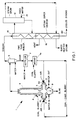
- the Figure of the Drawing is a schematic representation of preferred apparatus useful in and a pictorial process flow diagram for carrying out a preferred embodiment of the process of the present invention.
- first and second streams comprising oxygen or an oxygen-containing gas, such as, for example, air or oxygen-enriched air, and a first increment of a slurry of particulate carbonaceous solids and liquid carrier enter apparatus 1 through mixing nozzles 6 and 6a, respectively.
- Mixing nozzles 6 and 6a are located oppositely in and extend through ends 10 and 11, respectively, of horizontal fired slagging reactor 3.
- the feed streams are converted exothermically into steam, slag, char, vapor from the liquid carrier, hydrogen, carbon monoxide, carbon dioxide, minor amounts of other gases including methane, ammonia and hydrogen sulfide, and small entrained particles of sticky slag.
- the bulk of the slag formed as a by-product is drained from the bottom of the reactor 3 through a tap hole 2, to a slag quench section 9 and continuous depressurizing system (not shown).
- a slag quench section 9 and continuous depressurizing system (not shown).
- the steam, char, intermediate gases and entrained by products leave the reactor 3, they flow upward into an unfired second stage reactor 4 where a second increment of a slurry of particulate carbonaceous solids and liquid carrier is injected through nozzle 8.
- the heat produced in the reactor 3 and carried upward is used to effect the endothermic processes which take place in the unfired second stage reactor 4 including vaporization of the feed water, the carbon-steam reaction and the water-gas reaction between the CO and H2O.
- the carbon-steam reaction forms CO and H2; thus, increasing the yield of these usable gases.
- carbon monoxide reacts with water or steam to form carbon dioxide and additional hydrogen.
- the reactions occurring in unfired second stage reactor 4 thus enrich the gases emanating from the fired combustion reaction to produce a higher grade of synthesis gas and in doing so recover heat from the combustion reactor and cool the gases sufficiently that the slag entrained is cooled below the ash fusion initial deformation temperature and absorbed on the particulate carbonaceous material.
- the entrained slag droplets fuse by themselves or on the particulate material and do not adhere to heat transfer surfaces.
- the mixing or two-fluid nozzles 6 and 6a provide an atomized feed of the particulate carbonaceous solids slurry giving more efficient combustion of the carbonaceous solids.
- the nozzles are of the type having a central tube for the slurry and an annular space surrounding the central tube containing the atomizing gas which opens to a common mixing zone internally or externally to provide for the atomization of the slurry.
- the injection nozzle 8 of the unfired second stage reactor 4 can also be a nozzle of the type described hereinabove. Both mixing nozzles 6 and 6a and injection nozzle 8 can be of the internal or external mixing type, as is conventionally known to those skilled in the art.
- Exemplary of such nozzles and their use in a process similar to the present invention is the nozzle described in co-pending application Ser. No. 039,493, filed 4/16/87, and U.S. 4,679,733, to Lipp, issued July 14, 1987.
- the effluent from the unfired second stage reactor 4 is sent to a cyclone separator 5 which splits the effluent into a solids stream and a synthesis gas stream.
- the gas stream comprises hydrogen, carbon monoxide, a small amount of methane, H2S, ammonia, water vapor or steam, vapor from the liquid carrier, nitrogen, carbon dioxide and a small amount of particulate char.
- the solids stream comprises solidified ash and char formed in the unfired second stage reactor 4 or carried over from the horizontal reactor 3.
- the synthesis gas is then sent to fire-tube boiler 14 to produce steam from boiler feed water provided in feed water line 15 to steam drum 16.
- the solids stream comprising char and ash, separated from the gas stream in cyclone separator 5, contacts a liquid carrier to form a dilute slurry and goes to a settling vessel 7 for concentration.
- the settling vessel 7 may include separation and evaporation means (not shown) to provide a more concentrated slurry.
- a stream exiting vessel 7 forms a recycle char slurry stream.
- the preferred recycle slurry of char and liquid carrier defines a solids concentration of from 20 to 40 percent by weight, more preferably from 30 to 40 percent by weight.
- the slurry of char and liquid carrier may have a higher percentage of solids, however, too high a solids concentration makes the feed to fired horizontal reactor 3 too viscous for convenient pumping. It is desirable to mix the recycle slurry of char and liquid carrier with the feed slurry particulate carbonaceous solids and liquid carrier in a mixing vessel 7a before it is transferred into fired horizontal reactor 3 through mixing nozzles 6 and 6a.
- the vessel walls are steel and are lined with an insulating castable or ceramic fiber or refractory brick, such as a high chrome-containing brick in the first stage reactor and a dense medium, such as used in blast furnaces and non-slagging applications in the second stage, all of which are commercially available from several sources.
- an insulating castable or ceramic fiber or refractory brick such as a high chrome-containing brick in the first stage reactor and a dense medium, such as used in blast furnaces and non-slagging applications in the second stage, all of which are commercially available from several sources.
- the walls may be unlined by providing a "cold wall" system for fired horizontal reactor 3 and, optionally, unfired second stage reactor 4.
- cold wall means that the walls are cooled by an external cooling jacket, as is known conventionally in the art for prior art coal gasification systems.
- the slag freezes on the interior wall and provides for protection of the metal walls of the cooling jacket.
- reaction conditions in the process vary with the type of feed and the kind of conversion desired.
- the temperature of fired horizontal slagging reactor 3 is maintained from 2400°F (1300°C) to 3000°F (1650°C).
- the slag tends to become more viscous and freezes, causing buildup and eventual plugging of the reactor.
- reaction occurs readily; however, a less satisfactory product gas is produced, a lower overall thermal efficiency results and, thus a less economical operation obtains.
- unfired second stage reactor 4 a temperature of 1600°F (870°C) to 2000°F (1100°C) is desirable because at lower temperatures, the conversions of carbonaceous materials to gaseous products are lowered resulting in higher amounts of char production for reslurry and recycle.
- the upper temperature in unfired second stage reactor 4 depends primarily on the temperature in fired horizontal reactor 3.
- the hot intermediate product flowing upward from fired horizontal reactor 3 provides heat for the endothermic reactions occurring in the unfired second stage reactor 4.
- the temperature drop through the fire-tube boiler 14 and steam superheater 18 depends on the entering temperature and the heat transfer surface available.
- the inlet temperature will be similar to the unfired second stage reactor 4 outlet temperature, typically from 1600°F to 2000°F (870°C to 1100°C), and the high temperature heat recovery system, outlet temperature will be typically from 450°F to 550°F (230°C to 290°C).
- the temperatures in each portion of the apparatus are important, the specific reaction conditions, per se, are not critical to the process or apparatus of this invention within the given limits, except for the high temperature heat recovery system inlet temperature being below the temperature at which the slag particles produce fouling problems.
- the process of this invention is carried out at atmospheric or higher pressures.
- the pressure in reactor 3 is from 50 psig (345 kPa gage) to 600 psig (4140 kPa gage).
- 600 psig (4140 kPa gage) At pressures greater than 600 psig (4140 kPa gage), the capital cost of high pressure reaction equipment makes the process economically less attractive; while at pressures lower than 50 psig (345 kPa gage), the throughput of the gaseous products in the reactor 3 and unfired second stage reactor 4 is lower than economically attractive.
- the process runs at pressures of from 100 psig (690 kPa gage) to 400 psig (2760 kPa gage) and, most preferably, from 250 to 400 psig (1725 to 2760 kPa gage).
- the process is applicable to any particulate carbonaceous material.
- the nature and concentration of the carbonaceous material in the two stages need not be the same.
- the particulate carbonaceous material is coal which, without limitation, includes lignite, bituminous coal, subbituminous coal, or any combination thereof.
- Additional carbonaceous materials are coke from coal, coal char, coal liquefaction residues, particulate carbon, petroleum coke, carbonaceous solids derived from oil shale, tar sands, pitch, concentrated sewer sludge, bits of garbage, rubber and mixtures thereof.
- the foregoing exemplified materials can be in the form of comminuted solids, and for best materials handling and reaction characteristics, as pumpable slurries in a liquid carrier.
- the liquid carrier for carbonaceous solid materials can be any liquid which is capable of vaporizing and participating in the reactions to form desired gaseous products, particularly carbon monoxide and hydrogen.
- the most readily considered liquid carrier is water which forms steam in both reactor 3 and unfired second stage reactor 4.
- the steam is capable of reacting with carbon to form gaseous products which are constituents of synthesis gas.
- liquids other than water may be used to slurry the carbonaceous material.
- the liquid is water, but it may also be a hydrocarbon such as, for example, fuel oil, residual oil, petroleum, and liquid CO2.
- additional water or steam may be added to provide sufficient water for efficient reaction and for moderating the reactor temperature.
- oxygen-containing gas Any gas containing at least 20 percent oxygen may be used as the oxygen-containing gas fed to fired horizontal reactor 3.
- Preferred oxygen-containing gases include oxygen, air, and oxygen-enriched air with air as the oxygen-containing gas, the initial atomic ratio of free elemental oxygen to carbon in the reactor 3 is from 1.5:1 to 2.5:1. With oxygen, the ratio is from 1:1 to 2:1.
- the concentration of particulate carbonaceous material in the carrier liquid as a slurry is only that necessary to have a pumpable mixture. In general, the concentration ranges up to 70 percent by weight of the solid material. Preferably, the concentration of particulate carbonaceous material in the slurry ranges from 30 percent to 70 percent by weight in both the first and second stages of the process. More preferably, the concentration of coal in aqueous slurry is between 45 and 55 percent by weight.
- coal When coal is the feedstock, it is pulverized before being blended with a liquid carrier to form a slurry.
- a liquid carrier In general, any reasonably finely-divided carbonaceous material may be used, and any of the known methods of reducing the particle size of particulate solids may be employed. Examples of such methods include the use of ball, rod and hammer mills. While particle size is not critical, finely divided carbon particles are preferred. Powdered coal used as fuel in coal-fed power plants is typical. Such coal has a particle size distribution in which 90 percent by weight of the coal passes through a 200 mesh sieve, Tyler series.
- a slurry at 80°F (26.7°C) containing 52 percent pulverized subbituminous coal, i.e., Western Coal, and 48 percent water by weight was injected into the fired horizontal reactor 3 at a rate of 52 gallons/minute (195 liters/minute) for each of two opposed burner nozzles, together with a stream of air at 950°F (500°C) flowing at a rate of 90,000 pounds/hour (41,000 kg/hr).
- the temperature within the reactor 3 was 2600°F (1430°C) and the pressure was 120 psig (830 kPa gage).
- the steam and hot product gases made in the reactor 3 were passed upward into the unfired second stage reactor 4, where they were contacted with a second increment of slurry at 80°F (27°C) containing 52 percent pulverized subbituminous coal and 48 percent water by weight, flowing at a rate of 20 gallons/minute (75 liters/minute), along with atomizing steam at 465°F (240°C) flowing at a rate of 7,000 pounds/hour (3200 kg/hr).
- the heat generated in the reactor 3 was absorbed by the second increment of slurry, and used to convert the slurry into more steam and gaseous products.
- the temperature within the unfired second stage reactor 4 was 1800°F (980°C).
- the steam and gaseous products were discharged from the unfired second stage reactor 4 to the cyclone separator 5, where the mixture was separated into a gaseous stream and a solids stream.
- the discharge from the reactor comprised 10.4 percent hydrogen, 10.4 percent carbon monoxide, 15.0 percent carbon dioxide, 0.04 percent methane, and 65.0 percent nitrogen on a dry basis.
- the solids were mixed with water at 200-300°F (90 to 150°C) flowing at a rate of 300 gallons/minute (1100 liters/minute) to form a slurry which was concentrated to 25 percent solids by weight and recycled to the fired reactor 3 or discharged to waste treatment, as desired.
- a slurry at 80°F (27°C) containing 50 percent pulverized subbituminous coal and 50 percent water by weight was injected into the fired horizontal reactor 3 at a rate of 52 gallons/minute (195 liters/minute), together with a stream of air at 950°F (500°C) flowing at a rate of 90,000 pounds/hour (41,000 Kg/hr).
- the temperature within the reactor 3 was 2650°F (1450°C) and the pressure was 110 psig (758.42 kPa gage).
- the steam and hot product gases made in the reactor 3 were passed overhead into the unfired second stage reactor 4, and were there contacted with a second increment of slurry at 80°F (27°C) containing 40 percent pulverized subbituminous coal and 60 percent water by weight, flowing at a rate of 28 gallons/minute (106 liters/minute), along with atomizing steam at 465°F (240°C) flowing at a rate of 7,000 pounds/hour (3200 kg/hr).
- the heat generated in the reactor 3 was absorbed by the second increment of slurry, and used to convert the slurry into more steam and gaseous products.
- the temperature within the unfired second stage reactor 4 was 1800°F (980°C).
- the steam and gaseous products were discharged from the unfired second stage reactor 4 to the cyclone separator 5, where the mixture was separated into a gaseous stream and a solids stream.
- the gaseous products discharged overhead from the reactor 3 comprised 9.5 percent hydrogen, 10.2 percent carbon monoxide, 16.5 percent carbon dioxide, 0.07 percent methane, and 63.6 percent nitrogen on a dry basis.
- the gaseous products discharged overhead from the cyclone separator 5 at a rate of 112,000 pounds/hour (51,000 kg/hr) comprised 12 percent hydrogen, 10.0 percent carbon monoxide, 11.0 percent carbon dioxide, 0.5 percent methane and 66.4 percent nitrogen on a dry basis.
- the solids were mixed with water at 200-300°F (90 to 150°C) flowing at a rate of 300 gallons/minute (1100 liters/minute) to form a slurry which was then concentrated to 25 percent solids by weight and recycled to the fired reactor 3 or discharged to waste treatment, as desired.
- a slurry of pulverized lignite and water was used as feed to a reactor similar to that illustratively shown as the apparatus 1 of Figure 1.
- Oxygen of 99.6 percent purity was used as the oxygen-containing gas instead of air.
- a slurry at 75°F (24°C) containing 44.5 percent dry lignite by weight was injected into the fired horizontal reactor 3 at a rate of 2930 pounds/hour (1330 kg/hr), together with oxygen at 63°F (17°C) flowing at a rate of 1621 pounds/hour (740 Kg/hr).
- the temperature within the reactor 3 was 2500°F (1370°C), and the pressure was 240 psig (1655 kPa gage).
- One hundred pounds/hour (45 kg/hr) of nitrogen was added to the fired horizontal reactor 3 via instrument purges.
- the steam and hot product gases generated in the fired horizontal reactor 3 were passed upward into the unfired second stage reactor 4, and were there contacted with a second increment of slurry at 75°F (24°C) containing 44.5 percent dry lignite by weight flowing at a rate of 874 pounds/hour (400 Kg/hr), along with atomizing steam at 465°F (240°C) flowing at a rate of 161 pounds/hour (73 kg/hr).
- heat generated in the fired horizontal reactor 3 was absorbed by the second increment of slurry, and used to convert the slurry into more steam and gaseous products.
- the temperature within the unfired second stage reactor 4 was 1840°F (1000°C).
- the steam and gaseous products were discharged from the unfired second stage reactor 4 into the cyclone separator 5, where the mixture was separated into a gaseous stream and a solids stream.
- the solids stream was added to water and discharged.
- the discharge from the reactor 3 comprised 43.3 percent hydrogen, 26.6 percent carbon monoxide, 23.3 percent carbon dioxide, 0.8 percent methane, and 5.9 percent nitrogen by volume on a dry basis.
- the gas stream discharged from the cyclone comprised 48.8 percent hydrogen, 22.2 percent carbon monoxide, 23.3 percent carbon dioxide, 2.2 percent methane, and 3.5 percent nitrogen by volume on a dry basis.
- the feed slurry was a mixture of 0.926 volume fraction subbituminous coal slurry at 51 percent solids and 0.074 volume fraction char slurry at 30 percent solids.
- the temperature within the reactor 3 was 2840°F (1560°C) and the pressure was 120 psig (827 kPa gage).
- the steam and hot product gases made in the reactor 3 were passed overhead into the unfired second stage reactor 4, and were there contacted with a second increment of slurry at 90°F (32°C) containing 50 percent pulverized sub-bituminous coal and 50 percent water by weight, flowing at a rate of 25 gallons/minute (95 liters/minute), along with atomizing steam at 465°F (240°C) flowing at a rate of 7,000 pounds/hour (3180 kg/hr).
- the heat generated in the reactor 3 was absorbed by the second increment of slurry, and used to convert the slurry into more steam and gaseous products.
- the temperature within the heat recovery unit 4 was 1920°F (1050°C).
- the steam and gaseous products were discharged from the unfired second stage reactor 4 to the cyclone separator 5, where the mixture was separated into a gaseous stream and a solids stream.
- the gaseous products discharged overhead from the reactor 3 comprised 32.7 percent hydrogen, 31.5 percent carbon monoxide, 30.5 percent carbon dioxide, 0 percentmethane, and 5.3 percent nitrogen on a dry basis.
- the gaseous products discharged overhead from the cyclone separator 5 at a rate of 50,504 pounds/hour (23,300 kg/hr) comprised 36.1 percent hydrogen, 26.7 percent carbon monoxide, 31.8 percent carbon dioxide, 0.5 percent methane and 4.9 percent nitrogen on a dry basis.
- the solids from the bottom of the cyclone were mixed with water at 200 to 300°F (93 to 149°C) flowing at a rate of 300 gallons/minute (1135 liters/minute) to form a slurry which was then concentrated to about 25 percent solids by weight and recycled to the fired reactor 3.
- a slurry feed rate of 230 gallons per minute (1050 liters/minute) at 75°F (24°C) of 48.7 percent water and 51.3 percent Wyoming subbituminous coal with an approximate Ultimate Analysis of 68.5 percent carbon, 4.7 percent hydrogen, 0.8 percent nitrogen, 0.35 percent sulfur, 19.05 percent oxygen, and 6.6 percent ash was used to feed the coal slurry with 1.11 pounds of oxygen per pound of solids (1.11 kg oxygen/ kg solids) to an entrained flow, horizontal, fired slagging reactor, such as illustrated in Fig. 1, operated at 2650°F (1450°C) and 270 psig (1860 kPa gage).
- the process produced 187,400 pounds/hr (85,000 kg/hr) of synthesis gas, consisting of 39 percent hydrogen, 30 percent carbon dioxide, 28 percent carbon monoxide, and 3 percent nitrogen (volume percent).
- the synthesis gas was quenched upon exiting the reactor, using water to decrease the temperature.
- the gaseous products were then led to a cyclone to remove char and fly ash, except for small i.e. less than 5 micrometer size particles of slag and tar products.
- the gaseous products were then led through an extended enlarged tubular vessel to increase residence time and then enter the fire-tube boiler at about 1670°F (910°C). After heat recovery in the fire-tube boiler, the synthesis gas was fed to a venturi scrubber, low temperature heat recovery and conventional gas scrubbing equipment to produce a clean gas product for turbine or chemical synthesis.
- the fire-tube boiler plugged to inoperability in 37 hours of operation.
- the plug consisted of fly ash particles ( ⁇ 5 micrometers in size) stuck together forming larger flow restricting deposits.
- This example illustrates that operation of the unfired second stage reactor 4 in two-stage gasifier shown schematically in Fig. 1 produces synthesis gas which is non-fouling and thus aids in the operation of the fire-tube boiler.
- a slurry of 49.5 percent water and 50.5 percent Wyoming subbituminous coal having an Ultimate Analysis similar to Example 5 was fed at a rate of 340.3 gallons/min. (1290 liters/min.) with a ratio of 1.12 pounds of oxygen/ pound of solids (1. 12 kg oxygen/kg solids) to the same horizontal, entrained flow, fired slagging reactor as in Example 5.
- the reactor was operated at 2617°F (1400°C) and 343 psig (about 2365 kPa gage) and produced 244,900 lb/hr (11,000 kg/hr) of synthesis gas, analyzing 29.4 percent carbon monoxide, 1.9 percent methane, 28.1 percent carbon dioxide, 38.8 percent hydrogen, 1.8 percent nitrogen.
- This gas stream was quenched by a stream of slurry injected into the unfired second stage reactor 4 at a rate of 33 gallons/minute (125 liters/min.).
- the slurry was also Wyoming subbituminous coal having 46.9% water and 53.1% coal.
- the gaseous product was further water quenched and then passed through a larger diameter tubular reactor and into the fire-tube boiler at 1751°F (105°C) and a superficial tube velocity of 127 feet/sec. (39 meters/sec.).
- the gas exiting the boiler then proceeded through a venturi scrubber, low temperature heat recovery, and conventional gas scrubbing to produce a clean synthetic gas.
- the product gas did not plug the fire-tube boiler, even after several hundred hours of operation.
- This Example further illustrates the efficacy of the use of unfired second stage reactor 4 to quench the product gases from combustion rector 3, enhance the product gas content, and prevent fouling of the fire-tube boiler.
- a slurry of 52.1 percent water and 47.9 percent Wyoming subbituminous coal, analyzing the same as that in Example 5 was fed at a rate of 373 gallons/min. (1400 liters/min.) to an entrained flow, horizontal fired slagging reactor with oxygen at a ratio of 1.14 pounds of oxygen per pound of solids.
- the gasifier operated at 2467°F (1300°C) and 400 psig (2760 kPa gage). There was produced 266,100 lb/hr (121,000 kg/hr) of synthesis gas analyzing 28 percent carbon monoxide, 1.3 percent methane, 30 percent carbon dioxide, 40 percent hydrogen and 2 percent nitrogen (dry mole percent).
- the quenched synthesis gas then passed through a fire-tube boiler an a superficial tube velocity of 108.36 feet/sec. (33.0 meters/sec.) without fouling the fire-tube boiler.
- a two-stage reactor which includes an apparatus for the partial oxidation of a slurry of particulate carbonaceous material with an oxygen-containing gas which apparatus comprises (a) a horizontal cylindrical insulated fired slagging reactor closed at both ends and having opposed burners substantially in alignment with the central longitudinal axis of said fired reactor, with a bottom slag tap hole and an upper product gas vent centrally located between said closed ends, (b) a transition piece which is a frustoconical insulated section having an upper outlet and a wider lower inlet aligned with and encompassing said upper vent, and (c) a vertical cylindrical insulated unfired second stage reactor closely communicating with said transition-piece and having a lower inlet encompassing and communicating with said transition piece upper outlet, an injector nozzle for quenching the product gases from said fired reactor, and an upper product gas outlet.
Abstract
Description
- This invention relates to the gasification of carbonaceous materials. More particularly, the invention relates to the conversion of a solid carbonaceous fuel into gaseous products having increased fuel value.
- Three basic processes have been developed for the gasification of carbonaceous materials such as coal. They are: (1) fixed-bed gasification, (2) fluidized-bed gasification, and (3) suspension or entrainment gasification. The present invention relates to the third type of process, suspension or entrainment gasification.
- An inherent disadvantage of entrainment gasifiers is that they generate hot product gases. The heat must be recovered from the gases in order to utilize fully the heating value of the coal. It is known to quench partial oxidation gasification reactions directly in water or steam according to U.S. 2,957,387, U.S. 3,000,711 and U.S. 3,723,345, or to partially cool the effluent gases by indirect heat exchange, as taught in U.S. 3,025,149. However, large amounts of high temperature heat are lost in quenching the effluent gases without enhancing the fuel value of the synthesis gas produced.
- Another disadvantage of entrainment gasifiers is that they produce a substantial excess temperature in the gas product which requires quenching or cooling for subsequent heat recovery in conventional radiant heat water tube boilers. Thus, the product gas must be substantially cooled before it can be conducted to heat recovery boilers. As such, substantial quantities of otherwise useful high temperature heat are lost. Further, the capital investment for radiant heat boilers is quite high. Therefore, an alternative heat recovery boiler is an economic necessity for the entrainment gasifier processes.
- A further disadvantage of entrainment gasifier processes is that sticky slag particles are carried through the partial gasification reactor and tend to foul the heat transfer surfaces of the heat recovery equipment.
- Some of the reactions in a coal gasifier are exothermic and some are endothermic. A coal gasification process in which the heat generated by the exothermic reactions is used to provide the heat required for the endothermic reactions would be extremely desirable and energy efficient. Thus, it is an object of the present invention to provide an exothermic reactor partially oxidizing carbonaceous material with an oxygen-containing gas combined with a unfired second stage reactor to permit the endothermic reactions to proceed efficiently by reacting additional carbonaceous material with water, producing enhanced quality synthesis gas. This and other objects are accomplished in accordance with the present invention as described hereinbelow.
- In general, the present invention provides a non-catalytic two-stage upflow process for gasification of carbonaceous fuels which produces a non-fouling gas product allowing the use of fire-tube waste heat recovery units. The first stage or step of the process comprises the combustion, in a fired horizontal slagging reaction zone, or first stage reactor, of a stream of oxygen-containing gas and a first increment of a slurry of particulate carbonaceous solids in a liquid carrier. The solids concentration of the slurry may be from 30 to 70 percent by weight. Combustion occurs at a temperature between 2400°F (1300°C) and 3000°F (1650°C) in the horizontal reactor zone by using opposed, facing horizontal burner nozzles. Preferably, the horizontal burner nozzles are also coaxial, but this is not required. The oxygen, carbonaceous solids and liquid carrier are converted into steam, vapor from the liquid carrier, slag, char, and gaseous combustion products. The slag which forms in the reactor flows by gravity to the bottom of the reactor and out of the reactor through a tap hole.
- In the second stage, or step, the steam, vapor from the liquid carrier, char, and gaseous products from the fired horizontal reactor are contacted, in an unfired vertical second stage reactor, with a second increment of slurry of particulate carbonaceous solids in a liquid carrier to yield steam, vapor from the liquid carrier, synthesis gas and char entrained in the gaseous effluent. As used herein, the term "unfired" means that further combustion is not promoted by the addition of a second oxygen-containing gas stream. The vertical second stage reactor does not promote additional combustion and exothermic reactions such as which occur in the fired horizontal reactor. In the vertical second stage reactor, endothermic reactions predominate using heat produced by the combustion in the fired horizontal reactor. The second increment of particulate carbonaceous solids in a liquid carrier is injected into the vertical second stage reactor by means of a nozzle, with steam or other atomizing gas for atomization of the slurry of particulate carbonaceous solids to provide better reaction. Injecting the second increment of slurry at a point downstream of the original injection point reduces the temperature of the gases exiting from the fired horizontal reactor and provides a more efficient use of the heat produced in the process. Thus, while the fired horizontal reactor is primarily a combustion reactor, the vertical second stage reactor is primarily a quench reactor which also increases the heating value of the gases. The solids concentration of the second increment of slurry is from 30 to 70 percent by weight. The temperature of the vertical second stage reactor is from 1600°F (870°C) to 2000°F (1100°C). In a preferred embodiment of the present process, the unfired vertical second stage reactor is connected directly to the top of the fired horizontal reactor so that the hot reaction products are conveyed directly from the horizontal reactor to the second stage reactor to minimize heat losses in the gaseous reaction products and entrained solids. Direct connection also has the advantage of maintaining temperatures to prevent the slag formed from cooling in the first stage horizontal reactor and forming solid deposits.
- The synthesis gas and char entrained in the gaseous effluent from the unfired vertical second stage reactor exit from the top and are separated in a cyclone separator. The char exiting the cyclone separator is mixed with a liquid carrier forming a dilute slurry which is thereafter concentrated in a settling tank to a solids concentration of from 10 to 30 percent by weight. Then from 5 to 20 percent of the concentrated, or recycle, char slurry, based on the total amount of solid carbon fuel to the first stage, is added to the first stage horizontal slagging reactor zone, preferably after mixing with one or more streams of particulate carbonaceous solids comprising the first increment fed to the horizontal fired slagging reactor.
- After exiting the cyclone, the gaseous products proceed into high temperature heat recovery system. Usually, such equipment would be a radiant heat type boiler or water-tube boiler, but in this instance the capital investment for such a boiler is extremely high. Therefore, a fire-tube boiler provides the necessary heat exchange capacity with the simplicity of operation and low capital investment involved to advantageously meet the requirements of heat recovery operations. The operation can be augmented by the further addition of a steam superheater.
- However, this additional equipment is only practical if the operation of the fired combustion reaction and the unfired second stage reaction step provide a gaseous stream which is non-fouling. If the synthesis gas contains heavy hydrocarbons of the nature of aromatic hydrocarbon compounds or tars which are not a problem in high temperature heat recovery. The gas also contains small particles of molten slag, of up to 5 micrometer size, which have an alkaline surface with a slightly lower melting temperature and tend to adhere to interior heat transfer surfaces, then the heat transfer surfaces of the boiler will become quickly fouled, inefficient, and eventually plugged. It is thus essential that the process of the present invention provide a gas product stream which is non-fouling and sufficiently cool to render the sticky slag particles more solid and less sticky. Thus, the present invention should cool the gas product stream to a temperature below the initial deformation temperature of the entrained slag particles in the presence of carbonaceous particulate material upon which the sticky slag can be absorbed.
- The Figure of the Drawing is a schematic representation of preferred apparatus useful in and a pictorial process flow diagram for carrying out a preferred embodiment of the process of the present invention.
- The following description illustrates the manner in which the principles of the present invention are applied, but is not to be construed in any sense as limiting the scope of the invention.
- More specifically, as shown in Figure 1, first and second streams comprising oxygen or an oxygen-containing gas, such as, for example, air or oxygen-enriched air, and a first increment of a slurry of particulate carbonaceous solids and liquid carrier enter apparatus 1 through mixing
nozzles nozzles ends 10 and 11, respectively, of horizontal firedslagging reactor 3. Within horizontal firedslagging reactor 3, the feed streams are converted exothermically into steam, slag, char, vapor from the liquid carrier, hydrogen, carbon monoxide, carbon dioxide, minor amounts of other gases including methane, ammonia and hydrogen sulfide, and small entrained particles of sticky slag. The bulk of the slag formed as a by-product is drained from the bottom of thereactor 3 through atap hole 2, to aslag quench section 9 and continuous depressurizing system (not shown). As the steam, char, intermediate gases and entrained by products leave thereactor 3, they flow upward into an unfiredsecond stage reactor 4 where a second increment of a slurry of particulate carbonaceous solids and liquid carrier is injected throughnozzle 8. The heat produced in thereactor 3 and carried upward is used to effect the endothermic processes which take place in the unfiredsecond stage reactor 4 including vaporization of the feed water, the carbon-steam reaction and the water-gas reaction between the CO and H₂O. The carbon-steam reaction forms CO and H₂; thus, increasing the yield of these usable gases. In the water-gas reaction, carbon monoxide reacts with water or steam to form carbon dioxide and additional hydrogen. The reactions occurring in unfiredsecond stage reactor 4 thus enrich the gases emanating from the fired combustion reaction to produce a higher grade of synthesis gas and in doing so recover heat from the combustion reactor and cool the gases sufficiently that the slag entrained is cooled below the ash fusion initial deformation temperature and absorbed on the particulate carbonaceous material. By cooling to below the initial deformation temperature (2000 to 2100°F or 1100 to 1150°C) the entrained slag droplets fuse by themselves or on the particulate material and do not adhere to heat transfer surfaces. - The mixing or two-
fluid nozzles injection nozzle 8 of the unfiredsecond stage reactor 4 can also be a nozzle of the type described hereinabove. Both mixingnozzles injection nozzle 8 can be of the internal or external mixing type, as is conventionally known to those skilled in the art. Exemplary of such nozzles and their use in a process similar to the present invention is the nozzle described in co-pending application Ser. No. 039,493, filed 4/16/87, and U.S. 4,679,733, to Lipp, issued July 14, 1987. - As further shown in Figure 1, the effluent from the unfired
second stage reactor 4 is sent to acyclone separator 5 which splits the effluent into a solids stream and a synthesis gas stream. The gas stream comprises hydrogen, carbon monoxide, a small amount of methane, H₂S, ammonia, water vapor or steam, vapor from the liquid carrier, nitrogen, carbon dioxide and a small amount of particulate char. The solids stream comprises solidified ash and char formed in the unfiredsecond stage reactor 4 or carried over from thehorizontal reactor 3. The synthesis gas is then sent to fire-tube boiler 14 to produce steam from boiler feed water provided infeed water line 15 to steamdrum 16. Steam produced inboiler 14 is sent to steamsuperheater 18, which recovers additional heat values and the now much cooler synthesis gas exits the heat recovery system by means ofline 20 for further use as the desired fuel-rich product gas, and the char is formed into a low concentration slurry, settled, combined and recycled with fresh carbonaceous solids/liquid carrier slurry and recycled to thereactor 3, as more fully described below. - The solids stream, comprising char and ash, separated from the gas stream in
cyclone separator 5, contacts a liquid carrier to form a dilute slurry and goes to a settlingvessel 7 for concentration. The settlingvessel 7 may include separation and evaporation means (not shown) to provide a more concentrated slurry. Astream exiting vessel 7 forms a recycle char slurry stream. The preferred recycle slurry of char and liquid carrier defines a solids concentration of from 20 to 40 percent by weight, more preferably from 30 to 40 percent by weight. The slurry of char and liquid carrier may have a higher percentage of solids, however, too high a solids concentration makes the feed to firedhorizontal reactor 3 too viscous for convenient pumping. It is desirable to mix the recycle slurry of char and liquid carrier with the feed slurry particulate carbonaceous solids and liquid carrier in a mixing vessel 7a before it is transferred into firedhorizontal reactor 3 through mixingnozzles - The materials of construction of the unfired
horizontal slagging reactor 3 and unfiredsecond stage reactor 4 are not critical. Preferably, but not necessarily, the vessel walls are steel and are lined with an insulating castable or ceramic fiber or refractory brick, such as a high chrome-containing brick in the first stage reactor and a dense medium, such as used in blast furnaces and non-slagging applications in the second stage, all of which are commercially available from several sources. Use of this type of system provides the high recovery of heat values from the carbonaceous solids used in the process. Optionally and alternatively, the walls may be unlined by providing a "cold wall" system for firedhorizontal reactor 3 and, optionally, unfiredsecond stage reactor 4. The term "cold wall", as used herein, means that the walls are cooled by an external cooling jacket, as is known conventionally in the art for prior art coal gasification systems. In such a system, the slag freezes on the interior wall and provides for protection of the metal walls of the cooling jacket. - The reaction conditions in the process vary with the type of feed and the kind of conversion desired. In general, the temperature of fired
horizontal slagging reactor 3 is maintained from 2400°F (1300°C) to 3000°F (1650°C). At temperatures lower than this, the slag tends to become more viscous and freezes, causing buildup and eventual plugging of the reactor. At temperatures above 3000°F (1650°C), reaction occurs readily; however, a less satisfactory product gas is produced, a lower overall thermal efficiency results and, thus a less economical operation obtains. In unfiredsecond stage reactor 4, a temperature of 1600°F (870°C) to 2000°F (1100°C) is desirable because at lower temperatures, the conversions of carbonaceous materials to gaseous products are lowered resulting in higher amounts of char production for reslurry and recycle. The upper temperature in unfiredsecond stage reactor 4 depends primarily on the temperature in firedhorizontal reactor 3. The hot intermediate product flowing upward from firedhorizontal reactor 3 provides heat for the endothermic reactions occurring in the unfiredsecond stage reactor 4. The temperature drop through the fire-tube boiler 14 andsteam superheater 18 depends on the entering temperature and the heat transfer surface available. In general, the inlet temperature will be similar to the unfiredsecond stage reactor 4 outlet temperature, typically from 1600°F to 2000°F (870°C to 1100°C), and the high temperature heat recovery system, outlet temperature will be typically from 450°F to 550°F (230°C to 290°C). Although the temperatures in each portion of the apparatus are important, the specific reaction conditions, per se, are not critical to the process or apparatus of this invention within the given limits, except for the high temperature heat recovery system inlet temperature being below the temperature at which the slag particles produce fouling problems. - The process of this invention is carried out at atmospheric or higher pressures. Generally, the pressure in
reactor 3 is from 50 psig (345 kPa gage) to 600 psig (4140 kPa gage). At pressures greater than 600 psig (4140 kPa gage), the capital cost of high pressure reaction equipment makes the process economically less attractive; while at pressures lower than 50 psig (345 kPa gage), the throughput of the gaseous products in thereactor 3 and unfiredsecond stage reactor 4 is lower than economically attractive. Preferably, the process runs at pressures of from 100 psig (690 kPa gage) to 400 psig (2760 kPa gage) and, most preferably, from 250 to 400 psig (1725 to 2760 kPa gage). - The process is applicable to any particulate carbonaceous material. Moreover, the nature and concentration of the carbonaceous material in the two stages need not be the same. Preferably, however, the particulate carbonaceous material is coal which, without limitation, includes lignite, bituminous coal, subbituminous coal, or any combination thereof. Additional carbonaceous materials are coke from coal, coal char, coal liquefaction residues, particulate carbon, petroleum coke, carbonaceous solids derived from oil shale, tar sands, pitch, concentrated sewer sludge, bits of garbage, rubber and mixtures thereof. The foregoing exemplified materials can be in the form of comminuted solids, and for best materials handling and reaction characteristics, as pumpable slurries in a liquid carrier.
- The liquid carrier for carbonaceous solid materials can be any liquid which is capable of vaporizing and participating in the reactions to form desired gaseous products, particularly carbon monoxide and hydrogen. The most readily considered liquid carrier is water which forms steam in both
reactor 3 and unfiredsecond stage reactor 4. The steam is capable of reacting with carbon to form gaseous products which are constituents of synthesis gas. In addition, liquids other than water may be used to slurry the carbonaceous material. Preferably, the liquid is water, but it may also be a hydrocarbon such as, for example, fuel oil, residual oil, petroleum, and liquid CO₂. When the liquid carrier is a hydrocarbon, additional water or steam may be added to provide sufficient water for efficient reaction and for moderating the reactor temperature. - Any gas containing at least 20 percent oxygen may be used as the oxygen-containing gas fed to fired
horizontal reactor 3. Preferred oxygen-containing gases include oxygen, air, and oxygen-enriched air with air as the oxygen-containing gas, the initial atomic ratio of free elemental oxygen to carbon in thereactor 3 is from 1.5:1 to 2.5:1. With oxygen, the ratio is from 1:1 to 2:1. - The concentration of particulate carbonaceous material in the carrier liquid as a slurry is only that necessary to have a pumpable mixture. In general, the concentration ranges up to 70 percent by weight of the solid material. Preferably, the concentration of particulate carbonaceous material in the slurry ranges from 30 percent to 70 percent by weight in both the first and second stages of the process. More preferably, the concentration of coal in aqueous slurry is between 45 and 55 percent by weight.
- When coal is the feedstock, it is pulverized before being blended with a liquid carrier to form a slurry. In general, any reasonably finely-divided carbonaceous material may be used, and any of the known methods of reducing the particle size of particulate solids may be employed. Examples of such methods include the use of ball, rod and hammer mills. While particle size is not critical, finely divided carbon particles are preferred. Powdered coal used as fuel in coal-fed power plants is typical. Such coal has a particle size distribution in which 90 percent by weight of the coal passes through a 200 mesh sieve, Tyler series.
- The present invention is illustrated by the following illustrative examples, which are not to be construed, in any sense, as limiting the scope of the invention.
- A slurry at 80°F (26.7°C) containing 52 percent pulverized subbituminous coal, i.e., Western Coal, and 48 percent water by weight was injected into the fired
horizontal reactor 3 at a rate of 52 gallons/minute (195 liters/minute) for each of two opposed burner nozzles, together with a stream of air at 950°F (500°C) flowing at a rate of 90,000 pounds/hour (41,000 kg/hr). The temperature within thereactor 3 was 2600°F (1430°C) and the pressure was 120 psig (830 kPa gage). The steam and hot product gases made in thereactor 3 were passed upward into the unfiredsecond stage reactor 4, where they were contacted with a second increment of slurry at 80°F (27°C) containing 52 percent pulverized subbituminous coal and 48 percent water by weight, flowing at a rate of 20 gallons/minute (75 liters/minute), along with atomizing steam at 465°F (240°C) flowing at a rate of 7,000 pounds/hour (3200 kg/hr). - In the unfired
second stage reactor 4, the heat generated in thereactor 3 was absorbed by the second increment of slurry, and used to convert the slurry into more steam and gaseous products. The temperature within the unfiredsecond stage reactor 4 was 1800°F (980°C). The steam and gaseous products were discharged from the unfiredsecond stage reactor 4 to thecyclone separator 5, where the mixture was separated into a gaseous stream and a solids stream. The discharge from the reactor comprised 10.4 percent hydrogen, 10.4 percent carbon monoxide, 15.0 percent carbon dioxide, 0.04 percent methane, and 65.0 percent nitrogen on a dry basis. The gas stream discharged from thecyclone separator 5 at a rate of 100,000 pounds/hour (45000 Kg/hr) and comprised 11.8 percent hydrogen, 8.8 percent carbon monoxide, 15.4 percent carbon dioxide, 0.5 percent methane, and 63.4 percent nitrogen by volume on a dry basis. The solids were mixed with water at 200-300°F (90 to 150°C) flowing at a rate of 300 gallons/minute (1100 liters/minute) to form a slurry which was concentrated to 25 percent solids by weight and recycled to the firedreactor 3 or discharged to waste treatment, as desired. - A slurry at 80°F (27°C) containing 50 percent pulverized subbituminous coal and 50 percent water by weight was injected into the fired
horizontal reactor 3 at a rate of 52 gallons/minute (195 liters/minute), together with a stream of air at 950°F (500°C) flowing at a rate of 90,000 pounds/hour (41,000 Kg/hr). The temperature within thereactor 3 was 2650°F (1450°C) and the pressure was 110 psig (758.42 kPa gage). The steam and hot product gases made in thereactor 3 were passed overhead into the unfiredsecond stage reactor 4, and were there contacted with a second increment of slurry at 80°F (27°C) containing 40 percent pulverized subbituminous coal and 60 percent water by weight, flowing at a rate of 28 gallons/minute (106 liters/minute), along with atomizing steam at 465°F (240°C) flowing at a rate of 7,000 pounds/hour (3200 kg/hr). In the unfiredsecond stage reactor 4, the heat generated in thereactor 3 was absorbed by the second increment of slurry, and used to convert the slurry into more steam and gaseous products. The temperature within the unfiredsecond stage reactor 4 was 1800°F (980°C). The steam and gaseous products were discharged from the unfiredsecond stage reactor 4 to thecyclone separator 5, where the mixture was separated into a gaseous stream and a solids stream. The gaseous products discharged overhead from thereactor 3 comprised 9.5 percent hydrogen, 10.2 percent carbon monoxide, 16.5 percent carbon dioxide, 0.07 percent methane, and 63.6 percent nitrogen on a dry basis. The gaseous products discharged overhead from thecyclone separator 5 at a rate of 112,000 pounds/hour (51,000 kg/hr) comprised 12 percent hydrogen, 10.0 percent carbon monoxide, 11.0 percent carbon dioxide, 0.5 percent methane and 66.4 percent nitrogen on a dry basis. The solids were mixed with water at 200-300°F (90 to 150°C) flowing at a rate of 300 gallons/minute (1100 liters/minute) to form a slurry which was then concentrated to 25 percent solids by weight and recycled to the firedreactor 3 or discharged to waste treatment, as desired. - In this example, a slurry of pulverized lignite and water was used as feed to a reactor similar to that illustratively shown as the apparatus 1 of Figure 1. Oxygen of 99.6 percent purity was used as the oxygen-containing gas instead of air.
- A slurry at 75°F (24°C) containing 44.5 percent dry lignite by weight was injected into the fired
horizontal reactor 3 at a rate of 2930 pounds/hour (1330 kg/hr), together with oxygen at 63°F (17°C) flowing at a rate of 1621 pounds/hour (740 Kg/hr). The temperature within thereactor 3 was 2500°F (1370°C), and the pressure was 240 psig (1655 kPa gage). One hundred pounds/hour (45 kg/hr) of nitrogen was added to the firedhorizontal reactor 3 via instrument purges. The steam and hot product gases generated in the firedhorizontal reactor 3 were passed upward into the unfiredsecond stage reactor 4, and were there contacted with a second increment of slurry at 75°F (24°C) containing 44.5 percent dry lignite by weight flowing at a rate of 874 pounds/hour (400 Kg/hr), along with atomizing steam at 465°F (240°C) flowing at a rate of 161 pounds/hour (73 kg/hr). In the unfiredsecond stage reactor 4, heat generated in the firedhorizontal reactor 3 was absorbed by the second increment of slurry, and used to convert the slurry into more steam and gaseous products. The temperature within the unfiredsecond stage reactor 4 was 1840°F (1000°C). The steam and gaseous products were discharged from the unfiredsecond stage reactor 4 into thecyclone separator 5, where the mixture was separated into a gaseous stream and a solids stream. The solids stream was added to water and discharged. The discharge from thereactor 3 comprised 43.3 percent hydrogen, 26.6 percent carbon monoxide, 23.3 percent carbon dioxide, 0.8 percent methane, and 5.9 percent nitrogen by volume on a dry basis. The gas stream discharged from the cyclone comprised 48.8 percent hydrogen, 22.2 percent carbon monoxide, 23.3 percent carbon dioxide, 2.2 percent methane, and 3.5 percent nitrogen by volume on a dry basis. - A slurry at 200°F (93°C) containing 49.5 percent pulverized subbituminous coal and recycled char, the net being 50.5 percent water by weight, was injected into the fired
horizontal reactor 3 at a rate of 86 gallons/minute (325 liters/minute), together with a stream of oxygen flowing at a rate of 29,200 pounds/hour (13,000 kg/hr). The feed slurry was a mixture of 0.926 volume fraction subbituminous coal slurry at 51 percent solids and 0.074 volume fraction char slurry at 30 percent solids. The temperature within thereactor 3 was 2840°F (1560°C) and the pressure was 120 psig (827 kPa gage). The steam and hot product gases made in thereactor 3 were passed overhead into the unfiredsecond stage reactor 4, and were there contacted with a second increment of slurry at 90°F (32°C) containing 50 percent pulverized sub-bituminous coal and 50 percent water by weight, flowing at a rate of 25 gallons/minute (95 liters/minute), along with atomizing steam at 465°F (240°C) flowing at a rate of 7,000 pounds/hour (3180 kg/hr). In the unfiredsecond stage reactor 4, the heat generated in thereactor 3 was absorbed by the second increment of slurry, and used to convert the slurry into more steam and gaseous products. The temperature within theheat recovery unit 4 was 1920°F (1050°C). The steam and gaseous products were discharged from the unfiredsecond stage reactor 4 to thecyclone separator 5, where the mixture was separated into a gaseous stream and a solids stream. The gaseous products discharged overhead from thereactor 3 comprised 32.7 percent hydrogen, 31.5 percent carbon monoxide, 30.5 percent carbon dioxide, 0 percentmethane, and 5.3 percent nitrogen on a dry basis. The gaseous products discharged overhead from thecyclone separator 5 at a rate of 50,504 pounds/hour (23,300 kg/hr) comprised 36.1 percent hydrogen, 26.7 percent carbon monoxide, 31.8 percent carbon dioxide, 0.5 percent methane and 4.9 percent nitrogen on a dry basis. The solids from the bottom of the cyclone were mixed with water at 200 to 300°F (93 to 149°C) flowing at a rate of 300 gallons/minute (1135 liters/minute) to form a slurry which was then concentrated to about 25 percent solids by weight and recycled to the firedreactor 3. - The following example illustrates that a fire-tube boiler, as shown in the drawing of Fig. 1, will be plugged if the unfired
second stage reactor 4 was not employed in the process of the present invention. - A slurry feed rate of 230 gallons per minute (1050 liters/minute) at 75°F (24°C) of 48.7 percent water and 51.3 percent Wyoming subbituminous coal with an approximate Ultimate Analysis of 68.5 percent carbon, 4.7 percent hydrogen, 0.8 percent nitrogen, 0.35 percent sulfur, 19.05 percent oxygen, and 6.6 percent ash was used to feed the coal slurry with 1.11 pounds of oxygen per pound of solids (1.11 kg oxygen/ kg solids) to an entrained flow, horizontal, fired slagging reactor, such as illustrated in Fig. 1, operated at 2650°F (1450°C) and 270 psig (1860 kPa gage). The process produced 187,400 pounds/hr (85,000 kg/hr) of synthesis gas, consisting of 39 percent hydrogen, 30 percent carbon dioxide, 28 percent carbon monoxide, and 3 percent nitrogen (volume percent). The synthesis gas was quenched upon exiting the reactor, using water to decrease the temperature. The gaseous products were then led to a cyclone to remove char and fly ash, except for small i.e. less than 5 micrometer size particles of slag and tar products. The gaseous products were then led through an extended enlarged tubular vessel to increase residence time and then enter the fire-tube boiler at about 1670°F (910°C). After heat recovery in the fire-tube boiler, the synthesis gas was fed to a venturi scrubber, low temperature heat recovery and conventional gas scrubbing equipment to produce a clean gas product for turbine or chemical synthesis.
- During operation under the above conditions, the fire-tube boiler plugged to inoperability in 37 hours of operation. The plug consisted of fly ash particles (≦5 micrometers in size) stuck together forming larger flow restricting deposits.
- This example illustrates that operation of the unfired
second stage reactor 4 in two-stage gasifier shown schematically in Fig. 1 produces synthesis gas which is non-fouling and thus aids in the operation of the fire-tube boiler. - A slurry of 49.5 percent water and 50.5 percent Wyoming subbituminous coal having an Ultimate Analysis similar to Example 5 was fed at a rate of 340.3 gallons/min. (1290 liters/min.) with a ratio of 1.12 pounds of oxygen/ pound of solids (1. 12 kg oxygen/kg solids) to the same horizontal, entrained flow, fired slagging reactor as in Example 5. The reactor was operated at 2617°F (1400°C) and 343 psig (about 2365 kPa gage) and produced 244,900 lb/hr (11,000 kg/hr) of synthesis gas, analyzing 29.4 percent carbon monoxide, 1.9 percent methane, 28.1 percent carbon dioxide, 38.8 percent hydrogen, 1.8 percent nitrogen. This gas stream was quenched by a stream of slurry injected into the unfired
second stage reactor 4 at a rate of 33 gallons/minute (125 liters/min.). The slurry was also Wyoming subbituminous coal having 46.9% water and 53.1% coal. The gaseous product was further water quenched and then passed through a larger diameter tubular reactor and into the fire-tube boiler at 1751°F (105°C) and a superficial tube velocity of 127 feet/sec. (39 meters/sec.). The gas exiting the boiler then proceeded through a venturi scrubber, low temperature heat recovery, and conventional gas scrubbing to produce a clean synthetic gas. The product gas did not plug the fire-tube boiler, even after several hundred hours of operation. - This Example further illustrates the efficacy of the use of unfired
second stage reactor 4 to quench the product gases fromcombustion rector 3, enhance the product gas content, and prevent fouling of the fire-tube boiler. - A slurry of 52.1 percent water and 47.9 percent Wyoming subbituminous coal, analyzing the same as that in Example 5 was fed at a rate of 373 gallons/min. (1400 liters/min.) to an entrained flow, horizontal fired slagging reactor with oxygen at a ratio of 1.14 pounds of oxygen per pound of solids. The gasifier operated at 2467°F (1300°C) and 400 psig (2760 kPa gage). There was produced 266,100 lb/hr (121,000 kg/hr) of synthesis gas analyzing 28 percent carbon monoxide, 1.3 percent methane, 30 percent carbon dioxide, 40 percent hydrogen and 2 percent nitrogen (dry mole percent). The gaseous products passed into the unfired
second stage reactor 4 and were quenched to 1700°F (925°C) by injection of 53.8 gallons/min. (205 liters/min.) of slurry having 49 percent water and 51 percent Wyoming subbituminous coal of analysis similar to that above. The quenched synthesis gas then passed through a fire-tube boiler an a superficial tube velocity of 108.36 feet/sec. (33.0 meters/sec.) without fouling the fire-tube boiler. - As an additional aspect of this invention there is provided a two-stage reactor which includes an apparatus for the partial oxidation of a slurry of particulate carbonaceous material with an oxygen-containing gas which apparatus comprises (a) a horizontal cylindrical insulated fired slagging reactor closed at both ends and having opposed burners substantially in alignment with the central longitudinal axis of said fired reactor, with a bottom slag tap hole and an upper product gas vent centrally located between said closed ends, (b) a transition piece which is a frustoconical insulated section having an upper outlet and a wider lower inlet aligned with and encompassing said upper vent, and (c) a vertical cylindrical insulated unfired second stage reactor closely communicating with said transition-piece and having a lower inlet encompassing and communicating with said transition piece upper outlet, an injector nozzle for quenching the product gases from said fired reactor, and an upper product gas outlet.
- While certain representative embodiments and details have been shown for the purpose of illustrating the present invention, it will be apparent to those skilled in the art that various changes and modifications can be made therein without departing from the spirit and scope of the invention.
Claims (11)
Applications Claiming Priority (2)
| Application Number | Priority Date | Filing Date | Title |
|---|---|---|---|
| US80303185A | 1985-11-29 | 1985-11-29 | |
| US07/178,035 US4872886A (en) | 1985-11-29 | 1988-04-05 | Two-stage coal gasification process |
Publications (2)
| Publication Number | Publication Date |
|---|---|
| EP0423401A1 true EP0423401A1 (en) | 1991-04-24 |
| EP0423401B1 EP0423401B1 (en) | 1994-12-07 |
Family
ID=26873886
Family Applications (1)
| Application Number | Title | Priority Date | Filing Date |
|---|---|---|---|
| EP89310629A Expired - Lifetime EP0423401B1 (en) | 1985-11-29 | 1989-10-17 | Two-stage coal gasification process |
Country Status (8)
| Country | Link |
|---|---|
| US (1) | US4872886A (en) |
| EP (1) | EP0423401B1 (en) |
| KR (1) | KR0140194B1 (en) |
| CA (1) | CA2000446A1 (en) |
| DE (1) | DE68919851T2 (en) |
| ES (1) | ES2064455T3 (en) |
| GR (1) | GR3015038T3 (en) |
| WO (1) | WO1991005835A1 (en) |
Cited By (7)
| Publication number | Priority date | Publication date | Assignee | Title |
|---|---|---|---|---|
| WO1994026850A1 (en) * | 1993-05-13 | 1994-11-24 | Shell Oil Company | Method of quenching synthesis gas |
| EP1978074A1 (en) * | 2007-04-06 | 2008-10-08 | Waterim Ltd | Apparatus for the purification of a synthesis gas flow obtained from the gasification of refuses and/or biomasses |
| US7556659B2 (en) * | 2004-04-09 | 2009-07-07 | Hyun Yong Kim | High temperature reformer |
| WO2010037602A2 (en) * | 2008-09-30 | 2010-04-08 | Siemens Aktiengesellschaft | Utilisation of the perceptible heat of crude gas during entrained flow gasification |
| WO2010096278A3 (en) * | 2009-02-20 | 2010-12-29 | Conocophillips Company | Carbon dioxide rich off-gas from a two stage gasification process |
| WO2012034654A1 (en) * | 2010-09-15 | 2012-03-22 | Thyssenkrupp Uhde Gmbh | Method for generating synthesis gas |
| ES2535687A1 (en) * | 2015-03-23 | 2015-05-13 | Ingelia, S.L. | System and method of gasification of a liquid substrate (Machine-translation by Google Translate, not legally binding) |
Families Citing this family (77)
| Publication number | Priority date | Publication date | Assignee | Title |
|---|---|---|---|---|
| SE470213B (en) * | 1992-03-30 | 1993-12-06 | Nonox Eng Ab | Methods and apparatus for producing fuels from solid carbonaceous natural fuels |
| US5327726A (en) * | 1992-05-22 | 1994-07-12 | Foster Wheeler Energy Corporation | Staged furnaces for firing coal pyrolysis gas and char |
| US5243922A (en) * | 1992-07-31 | 1993-09-14 | Institute Of Gas Technology | Advanced staged combustion system for power generation from coal |
| US5370715A (en) * | 1993-04-27 | 1994-12-06 | Kortzeborn; Robert N. | Waste destructor and method of converting wastes to fluid fuel |
| US5433760A (en) * | 1993-05-13 | 1995-07-18 | Shell Oil Company | Method of quenching synthesis gas |
| US6027540A (en) * | 1997-03-31 | 2000-02-22 | Destec Energy, Inc. | Apparatus for removal of particulate matter from gas streams |
| DE69831407T2 (en) * | 1997-06-06 | 2006-06-14 | Texaco Development Corp | OXYGEN FLOW CONTROL FOR GASIFICATION |
| CN1118544C (en) * | 2000-01-13 | 2003-08-20 | 华东理工大学 | Two segments combined gasifying process and equipment based on coal |
| US7070758B2 (en) | 2000-07-05 | 2006-07-04 | Peterson Oren V | Process and apparatus for generating hydrogen from oil shale |
| EP1348011B1 (en) * | 2000-12-04 | 2010-03-17 | Emery Energy Company L.L.C. | Multi-faceted gasifier and related methods |
| US20030153797A1 (en) * | 2001-10-30 | 2003-08-14 | Onsite Technolgy Llc | Process for producing a liquid fuel composition |
| US8394863B2 (en) | 2003-08-21 | 2013-03-12 | Pearson Technologies, Inc. | Process and apparatus for the production of useful products from carbonaceous feedstock |
| TW200519073A (en) | 2003-08-21 | 2005-06-16 | Pearson Technologies Inc | Process and apparatus for the production of useful products from carbonaceous feedstock |
| US20060101715A1 (en) * | 2004-11-17 | 2006-05-18 | Karel Vlok | Apparatus and method for coal gasification |
| US20060165582A1 (en) * | 2005-01-27 | 2006-07-27 | Brooker Donald D | Production of synthesis gas |
| DE102005041931B4 (en) * | 2005-09-03 | 2018-07-05 | Siemens Aktiengesellschaft | Apparatus for producing synthesis gases by partial oxidation of ash-containing fuels under elevated pressure with partial quenching of the raw gas and waste heat recovery |
| US8211191B2 (en) * | 2007-08-07 | 2012-07-03 | Phillips 66 Company | Upright gasifier |
| US7993131B2 (en) * | 2007-08-28 | 2011-08-09 | Conocophillips Company | Burner nozzle |
| US8328889B2 (en) * | 2007-12-12 | 2012-12-11 | Kellogg Brown & Root Llc | Efficiency of gasification processes |
| WO2009086407A2 (en) | 2007-12-28 | 2009-07-09 | Greatpoint Energy, Inc. | Steam generating slurry gasifier for the catalytic gasification of a carbonaceous feedstock |
| CA2713661C (en) | 2007-12-28 | 2013-06-11 | Greatpoint Energy, Inc. | Process of making a syngas-derived product via catalytic gasification of a carbonaceous feedstock |
| US8221513B2 (en) * | 2008-01-29 | 2012-07-17 | Kellogg Brown & Root Llc | Low oxygen carrier fluid with heating value for feed to transport gasification |
| WO2009111331A2 (en) | 2008-02-29 | 2009-09-11 | Greatpoint Energy, Inc. | Steam generation processes utilizing biomass feedstocks |
| WO2009111332A2 (en) | 2008-02-29 | 2009-09-11 | Greatpoint Energy, Inc. | Reduced carbon footprint steam generation processes |
| US8652222B2 (en) | 2008-02-29 | 2014-02-18 | Greatpoint Energy, Inc. | Biomass compositions for catalytic gasification |
| US8297542B2 (en) | 2008-02-29 | 2012-10-30 | Greatpoint Energy, Inc. | Coal compositions for catalytic gasification |
| WO2009111345A2 (en) | 2008-02-29 | 2009-09-11 | Greatpoint Energy, Inc. | Catalytic gasification particulate compositions |
| US8286901B2 (en) | 2008-02-29 | 2012-10-16 | Greatpoint Energy, Inc. | Coal compositions for catalytic gasification |
| US8349039B2 (en) | 2008-02-29 | 2013-01-08 | Greatpoint Energy, Inc. | Carbonaceous fines recycle |
| WO2009124019A2 (en) | 2008-04-01 | 2009-10-08 | Greatpoint Energy, Inc. | Sour shift process for the removal of carbon monoxide from a gas stream |
| US8999020B2 (en) * | 2008-04-01 | 2015-04-07 | Greatpoint Energy, Inc. | Processes for the separation of methane from a gas stream |
| US8460410B2 (en) * | 2008-08-15 | 2013-06-11 | Phillips 66 Company | Two stage entrained gasification system and process |
| CN103865585A (en) | 2008-09-19 | 2014-06-18 | 格雷特波因特能源公司 | Gasification device of a Carbonaceous Feedstock |
| US8647402B2 (en) | 2008-09-19 | 2014-02-11 | Greatpoint Energy, Inc. | Processes for gasification of a carbonaceous feedstock |
| WO2010033846A2 (en) | 2008-09-19 | 2010-03-25 | Greatpoint Energy, Inc. | Char methanation catalyst and its use in gasification processes |
| JP4898759B2 (en) * | 2008-10-22 | 2012-03-21 | 三菱重工業株式会社 | Coal gasifier |
| KR101275429B1 (en) | 2008-10-23 | 2013-06-18 | 그레이트포인트 에너지, 인크. | Processes for gasification of a carbonaceous feedstock |
| US20100132257A1 (en) * | 2008-12-01 | 2010-06-03 | Kellogg Brown & Root Llc | Systems and Methods for Increasing Carbon Dioxide in Gasification |
| TWI558807B (en) * | 2008-12-17 | 2016-11-21 | 祿幕斯科技公司 | Gasification system and process with staged slurry addition |
| TW201026395A (en) * | 2008-12-24 | 2010-07-16 | Conocophillips Co | Tar-free gasification system and process |
| EP2370549A1 (en) | 2008-12-30 | 2011-10-05 | Greatpoint Energy, Inc. | Processes for preparing a catalyzed coal particulate |
| US8734547B2 (en) | 2008-12-30 | 2014-05-27 | Greatpoint Energy, Inc. | Processes for preparing a catalyzed carbonaceous particulate |
| US8119077B2 (en) * | 2009-01-07 | 2012-02-21 | General Electric Company | Control joints in refractory lining systems and methods |
| ES2703390T3 (en) | 2009-03-09 | 2019-03-08 | Treetotextile Ab | Manufactured cellulose manufacturing process combined with a pulp mill recovery system |
| US8357216B2 (en) * | 2009-04-01 | 2013-01-22 | Phillips 66 Company | Two stage dry feed gasification system and process |
| US8349046B2 (en) * | 2009-04-30 | 2013-01-08 | Enerjetik Llc | Method of making syngas and apparatus therefor |
| US8268899B2 (en) | 2009-05-13 | 2012-09-18 | Greatpoint Energy, Inc. | Processes for hydromethanation of a carbonaceous feedstock |
| JP5269251B2 (en) | 2009-05-13 | 2013-08-21 | グレイトポイント・エナジー・インコーポレイテッド | Process for the hydrogenation methanation of carbonaceous feedstock |
| US8728182B2 (en) | 2009-05-13 | 2014-05-20 | Greatpoint Energy, Inc. | Processes for hydromethanation of a carbonaceous feedstock |
| CA2773845C (en) | 2009-10-19 | 2014-06-03 | Greatpoint Energy, Inc. | Integrated enhanced oil recovery process |
| CN102667057B (en) | 2009-10-19 | 2014-10-22 | 格雷特波因特能源公司 | Integrated enhanced oil recovery process |
| CN102639435A (en) | 2009-12-17 | 2012-08-15 | 格雷特波因特能源公司 | Integrated enhanced oil recovery process |
| US8696774B2 (en) * | 2010-01-07 | 2014-04-15 | General Electric Company | Gasification system and method using fuel injectors |
| CN102754266B (en) | 2010-02-23 | 2015-09-02 | 格雷特波因特能源公司 | integrated hydrogenation methanation fuel cell power generation |
| US8652696B2 (en) | 2010-03-08 | 2014-02-18 | Greatpoint Energy, Inc. | Integrated hydromethanation fuel cell power generation |
| CN102858925B (en) | 2010-04-26 | 2014-05-07 | 格雷特波因特能源公司 | Hydromethanation of carbonaceous feedstock with vanadium recovery |
| CA2793893A1 (en) | 2010-05-28 | 2011-12-01 | Greatpoint Energy, Inc. | Conversion of liquid heavy hydrocarbon feedstocks to gaseous products |
| US8748687B2 (en) | 2010-08-18 | 2014-06-10 | Greatpoint Energy, Inc. | Hydromethanation of a carbonaceous feedstock |
| CN103210068B (en) | 2010-11-01 | 2015-07-08 | 格雷特波因特能源公司 | Hydromethanation of a carbonaceous feedstock |
| CN104711026A (en) | 2011-02-23 | 2015-06-17 | 格雷特波因特能源公司 | Hydromethanation of a carbonaceous feedstock with nickel recovery |
| US9127221B2 (en) | 2011-06-03 | 2015-09-08 | Greatpoint Energy, Inc. | Hydromethanation of a carbonaceous feedstock |
| AU2011370246B2 (en) | 2011-06-10 | 2016-09-29 | Bharat Petroleum Corporation Limited | Process for co-gasification of two or more carbonaceous feedstocks and apparatus thereof |
| US9012524B2 (en) | 2011-10-06 | 2015-04-21 | Greatpoint Energy, Inc. | Hydromethanation of a carbonaceous feedstock |
| PT2875103T (en) | 2012-06-26 | 2020-06-23 | Lummus Technology Inc | Two stage gasification with dual quench |
| US9102882B2 (en) | 2012-09-04 | 2015-08-11 | General Electric Company | Gasification system and method |
| US9328920B2 (en) | 2012-10-01 | 2016-05-03 | Greatpoint Energy, Inc. | Use of contaminated low-rank coal for combustion |
| CN104685039B (en) | 2012-10-01 | 2016-09-07 | 格雷特波因特能源公司 | Graininess low rank coal raw material of agglomeration and application thereof |
| US9273260B2 (en) | 2012-10-01 | 2016-03-01 | Greatpoint Energy, Inc. | Agglomerated particulate low-rank coal feedstock and uses thereof |
| US9034061B2 (en) | 2012-10-01 | 2015-05-19 | Greatpoint Energy, Inc. | Agglomerated particulate low-rank coal feedstock and uses thereof |
| WO2017151889A1 (en) * | 2016-03-04 | 2017-09-08 | Lummus Technology Inc. | Two-stage gasifier and gasification process with feedstock flexibility |
| JP6637797B2 (en) * | 2016-03-11 | 2020-01-29 | 三菱日立パワーシステムズ株式会社 | Carbon-containing raw material gasification system and method for setting oxidizing agent distribution ratio |
| US11220642B2 (en) * | 2017-08-08 | 2022-01-11 | Shandong University | Pulverized coal gasification device and process for producing high heating value coal gas with low carbon residue content |
| CN107641530A (en) * | 2017-11-13 | 2018-01-30 | 中国华能集团清洁能源技术研究院有限公司 | A kind of up two-part gasification installation |
| US10464872B1 (en) | 2018-07-31 | 2019-11-05 | Greatpoint Energy, Inc. | Catalytic gasification to produce methanol |
| US10344231B1 (en) | 2018-10-26 | 2019-07-09 | Greatpoint Energy, Inc. | Hydromethanation of a carbonaceous feedstock with improved carbon utilization |
| US10435637B1 (en) | 2018-12-18 | 2019-10-08 | Greatpoint Energy, Inc. | Hydromethanation of a carbonaceous feedstock with improved carbon utilization and power generation |
| US10618818B1 (en) | 2019-03-22 | 2020-04-14 | Sure Champion Investment Limited | Catalytic gasification to produce ammonia and urea |
Citations (7)
| Publication number | Priority date | Publication date | Assignee | Title |
|---|---|---|---|---|
| FR1190295A (en) * | 1957-01-22 | 1959-10-12 | Babcock & Wilcox Co | Introduction of crushed solid fuel into a high pressure reaction zone |
| FR2177089A1 (en) * | 1972-03-23 | 1973-11-02 | Bituminous Coal Research | |
| GB2051121A (en) * | 1979-05-31 | 1981-01-14 | Avco Everett Res Lab Inc | Gasification of carbonaceous material |
| EP0050863A1 (en) * | 1980-10-24 | 1982-05-05 | Hitachi, Ltd. | Process of and apparatus for gasifying coals |
| GB2106130A (en) * | 1981-09-04 | 1983-04-07 | Foster Wheeler Power Prod | Gasification |
| US4569680A (en) * | 1984-12-26 | 1986-02-11 | Combustion Engineering | Gasifier with economizer gas exit temperature control |
| EP0225146A2 (en) * | 1985-11-29 | 1987-06-10 | The Dow Chemical Company | Two-stage coal gasification process |
Family Cites Families (33)
| Publication number | Priority date | Publication date | Assignee | Title |
|---|---|---|---|---|
| US2905544A (en) * | 1951-05-17 | 1959-09-22 | Koppers Co Inc | Suspension process for the production of co and h2 from a solid carbonaceous fuel, oxygen and steam |
| US2716597A (en) * | 1951-06-12 | 1955-08-30 | Koppers Co Inc | Method and apparatus for the production of combustible gases from liquid fuels |
| NL83269C (en) * | 1951-07-14 | |||
| US2898204A (en) * | 1953-12-24 | 1959-08-04 | Koppers Co Inc | Process for production of combustible gases |
| US2963354A (en) * | 1956-06-27 | 1960-12-06 | Texaco Inc | Process for the gasification of solid carbonaceous fuels |
| US2961310A (en) * | 1957-01-22 | 1960-11-22 | Babcock & Wilcox Co | Comminuted solid fuel introduction into high pressure reaction zone |
| US3000711A (en) * | 1957-12-13 | 1961-09-19 | Texaco Inc | Coal gasification apparatus |
| US3025149A (en) * | 1958-06-05 | 1962-03-13 | Texaco Inc | Production of heating gas |
| US2987387A (en) * | 1958-12-30 | 1961-06-06 | Texaco Inc | Method for the production of carbon monoxide from solid fuels |
| US3544291A (en) * | 1968-04-22 | 1970-12-01 | Texaco Inc | Coal gasification process |
| US3607157A (en) * | 1969-07-23 | 1971-09-21 | Texaco Inc | Synthesis gas from petroleum coke |
| US3723345A (en) * | 1969-11-21 | 1973-03-27 | Texaco Development Corp | Synthesis gas process |
| US3784364A (en) * | 1971-11-04 | 1974-01-08 | Texaco Inc | Production of fuel gas |
| US3779725A (en) * | 1971-12-06 | 1973-12-18 | Air Prod & Chem | Coal gassification |
| US3844733A (en) * | 1972-03-23 | 1974-10-29 | Us Interior | Two-stage downflow gasification of coal |
| US3864100A (en) * | 1973-01-02 | 1975-02-04 | Combustion Eng | Method and apparatus for gasification of pulverized coal |
| US4060397A (en) * | 1974-02-21 | 1977-11-29 | Shell Internationale Research Maatschappij B.V. | Two stage partial combustion process for solid carbonaceous fuels |
| NL178134C (en) * | 1974-06-17 | 1986-02-03 | Shell Int Research | METHOD AND APPARATUS FOR TREATING A HOT PRODUCT GAS. |
| US3979188A (en) * | 1974-10-25 | 1976-09-07 | Foster Wheeler Energy Corporation | Partial oxidation carbon removal process |
| US3945809A (en) * | 1975-07-08 | 1976-03-23 | The United States Of America As Represented By The United States Energy Research And Development Administration | Method and apparatus for removing coarse unentrained char particles from the second stage of a two-stage coal gasifier |
| US3957460A (en) * | 1975-09-09 | 1976-05-18 | The United States Of America As Represented By The United States Energy Research And Development Administration | Oxidation of coal-water slurry feed to hydrogasifier |
| US4069024A (en) * | 1977-05-09 | 1978-01-17 | Combustion Engineering, Inc. | Two-stage gasification system |
| US4168956A (en) * | 1977-08-18 | 1979-09-25 | Combustion Engineering, Inc. | Method of operating a coal gasifier |
| DE2822862C2 (en) * | 1978-05-26 | 1984-01-05 | Ruhrchemie Ag, 4200 Oberhausen | Process for the production of gas mixtures containing hydrogen and carbon monoxide by gasifying carbon-containing, ash-forming fuels |
| US4278446A (en) * | 1979-05-31 | 1981-07-14 | Avco Everett Research Laboratory, Inc. | Very-high-velocity entrained-bed gasification of coal |
| US4247302A (en) * | 1979-07-13 | 1981-01-27 | Texaco Inc. | Process for gasification and production of by-product superheated steam |
| US4244706A (en) * | 1979-09-10 | 1981-01-13 | The United States Of America As Represented By The United States Department Of Energy | Process for gasifying carbonaceous material from a recycled condensate slurry |
| US4343627A (en) * | 1980-11-28 | 1982-08-10 | Combustion Engineering, Inc. | Method of operating a two-stage coal gasifier |
| US4319888A (en) * | 1980-12-12 | 1982-03-16 | Combustion Engineering, Inc. | Apparatus for mixing char-ash into coal stream |
| US4312639A (en) * | 1980-12-22 | 1982-01-26 | Atlantic Richfield Company | Process for heating solids for coal gasification |
| US4525175A (en) * | 1983-05-31 | 1985-06-25 | Texaco Inc. | High turn down burner for partial oxidation of slurries of solid fuel |
| US4547203A (en) * | 1984-03-30 | 1985-10-15 | Texaco Development Corporation | Partial oxidation process |
| US4705535A (en) * | 1986-03-13 | 1987-11-10 | The Dow Chemical Company | Nozzle for achieving constant mixing energy |
-
1988
- 1988-04-05 US US07/178,035 patent/US4872886A/en not_active Expired - Lifetime
-
1989
- 1989-10-10 WO PCT/US1989/004536 patent/WO1991005835A1/en active Application Filing
- 1989-10-11 CA CA002000446A patent/CA2000446A1/en not_active Abandoned
- 1989-10-17 ES ES89310629T patent/ES2064455T3/en not_active Expired - Lifetime
- 1989-10-17 DE DE68919851T patent/DE68919851T2/en not_active Expired - Lifetime
- 1989-10-17 EP EP89310629A patent/EP0423401B1/en not_active Expired - Lifetime
-
1991
- 1991-06-08 KR KR91700575A patent/KR0140194B1/en not_active IP Right Cessation
-
1995
- 1995-02-09 GR GR950400270T patent/GR3015038T3/en unknown
Patent Citations (7)
| Publication number | Priority date | Publication date | Assignee | Title |
|---|---|---|---|---|
| FR1190295A (en) * | 1957-01-22 | 1959-10-12 | Babcock & Wilcox Co | Introduction of crushed solid fuel into a high pressure reaction zone |
| FR2177089A1 (en) * | 1972-03-23 | 1973-11-02 | Bituminous Coal Research | |
| GB2051121A (en) * | 1979-05-31 | 1981-01-14 | Avco Everett Res Lab Inc | Gasification of carbonaceous material |
| EP0050863A1 (en) * | 1980-10-24 | 1982-05-05 | Hitachi, Ltd. | Process of and apparatus for gasifying coals |
| GB2106130A (en) * | 1981-09-04 | 1983-04-07 | Foster Wheeler Power Prod | Gasification |
| US4569680A (en) * | 1984-12-26 | 1986-02-11 | Combustion Engineering | Gasifier with economizer gas exit temperature control |
| EP0225146A2 (en) * | 1985-11-29 | 1987-06-10 | The Dow Chemical Company | Two-stage coal gasification process |
Non-Patent Citations (1)
| Title |
|---|
| PATENT ABSTRACTS OF JAPAN, vol. 9, no. 138 (C-286)[1861], 13th June 1985; & JP-A-60 23 485 (BABCOCK HITACHI K.K.) 06-02-1985 * |
Cited By (10)
| Publication number | Priority date | Publication date | Assignee | Title |
|---|---|---|---|---|
| WO1994026850A1 (en) * | 1993-05-13 | 1994-11-24 | Shell Oil Company | Method of quenching synthesis gas |
| US7556659B2 (en) * | 2004-04-09 | 2009-07-07 | Hyun Yong Kim | High temperature reformer |
| EP1978074A1 (en) * | 2007-04-06 | 2008-10-08 | Waterim Ltd | Apparatus for the purification of a synthesis gas flow obtained from the gasification of refuses and/or biomasses |
| WO2010037602A2 (en) * | 2008-09-30 | 2010-04-08 | Siemens Aktiengesellschaft | Utilisation of the perceptible heat of crude gas during entrained flow gasification |
| WO2010037602A3 (en) * | 2008-09-30 | 2010-09-10 | Siemens Aktiengesellschaft | Utilisation of the perceptible heat of crude gas during entrained flow gasification |
| WO2010096278A3 (en) * | 2009-02-20 | 2010-12-29 | Conocophillips Company | Carbon dioxide rich off-gas from a two stage gasification process |
| US7883682B2 (en) | 2009-02-20 | 2011-02-08 | Conocophillips Company | Carbon dioxide rich off-gas from a two stage gasification process |
| WO2012034654A1 (en) * | 2010-09-15 | 2012-03-22 | Thyssenkrupp Uhde Gmbh | Method for generating synthesis gas |
| US8877097B2 (en) | 2010-09-15 | 2014-11-04 | Thyssenkrupp Uhde Gmbh | Method for the generation of synthesis gas |
| ES2535687A1 (en) * | 2015-03-23 | 2015-05-13 | Ingelia, S.L. | System and method of gasification of a liquid substrate (Machine-translation by Google Translate, not legally binding) |
Also Published As
| Publication number | Publication date |
|---|---|
| US4872886A (en) | 1989-10-10 |
| KR920702858A (en) | 1992-10-28 |
| DE68919851D1 (en) | 1995-01-19 |
| GR3015038T3 (en) | 1995-05-31 |
| ES2064455T3 (en) | 1995-02-01 |
| EP0423401B1 (en) | 1994-12-07 |
| KR0140194B1 (en) | 1998-06-15 |
| DE68919851T2 (en) | 1995-07-06 |
| WO1991005835A1 (en) | 1991-05-02 |
| CA2000446A1 (en) | 1991-04-11 |
Similar Documents
| Publication | Publication Date | Title |
|---|---|---|
| EP0423401B1 (en) | Two-stage coal gasification process | |
| EP0225146B1 (en) | Two-stage coal gasification process | |
| CA2739498C (en) | Gasification system and process with staged slurry addition | |
| EP2321387B1 (en) | Two stage entrained gasification system and process | |
| US4436531A (en) | Synthesis gas from slurries of solid carbonaceous fuels | |
| US4588850A (en) | Process for the production of acetylene and synthesis or reduction gas from coal in an electric arc process | |
| US3715301A (en) | Multi-hydrotorting of coal | |
| US3715195A (en) | Multihydrotorting of coal | |
| US4778485A (en) | POX process with high temperature desulfurization of syngas | |
| US8252073B2 (en) | Tar-free gasification system and process | |
| US4778484A (en) | Partial oxidation process with second stage addition of iron containing additive | |
| JP2719424B2 (en) | Coal gasification method and apparatus | |
| EP0305047B1 (en) | High temperature desulfurization of synthesis gas | |
| AU638424B2 (en) | Coal gasification process and apparatus | |
| JPH04503526A (en) | Coal gasification method and equipment | |
| EP0148542B1 (en) | Synthesis gas from slurries of solid, carbonaceous fuels | |
| Schlinger | Coal gasification development and commercialization of the texaco coal gasification process | |
| NZ231018A (en) | Two-stage coal gasification process and apparatus |
Legal Events
| Date | Code | Title | Description |
|---|---|---|---|
| PUAI | Public reference made under article 153(3) epc to a published international application that has entered the european phase |
Free format text: ORIGINAL CODE: 0009012 |
|
| AK | Designated contracting states |
Kind code of ref document: A1 Designated state(s): BE DE ES FR GB GR IT NL SE |
|
| 17P | Request for examination filed |
Effective date: 19911017 |
|
| 17Q | First examination report despatched |
Effective date: 19920409 |
|
| GRAA | (expected) grant |
Free format text: ORIGINAL CODE: 0009210 |
|
| AK | Designated contracting states |
Kind code of ref document: B1 Designated state(s): BE DE ES FR GB GR IT NL SE |
|
| REF | Corresponds to: |
Ref document number: 68919851 Country of ref document: DE Date of ref document: 19950119 |
|
| ET | Fr: translation filed | ||
| ITF | It: translation for a ep patent filed |
Owner name: ING. A. GIAMBROCONO & C. S.R.L. |
|
| REG | Reference to a national code |
Ref country code: ES Ref legal event code: FG2A Ref document number: 2064455 Country of ref document: ES Kind code of ref document: T3 |
|
| REG | Reference to a national code |
Ref country code: GR Ref legal event code: FG4A Free format text: 3015038 |
|
| PLBE | No opposition filed within time limit |
Free format text: ORIGINAL CODE: 0009261 |
|
| STAA | Information on the status of an ep patent application or granted ep patent |
Free format text: STATUS: NO OPPOSITION FILED WITHIN TIME LIMIT |
|
| 26N | No opposition filed | ||
| REG | Reference to a national code |
Ref country code: GB Ref legal event code: 732E |
|
| NLS | Nl: assignments of ep-patents |
Owner name: DESTEC ENERGY, INC. |
|
| REG | Reference to a national code |
Ref country code: ES Ref legal event code: PC2A |
|
| PGFP | Annual fee paid to national office [announced via postgrant information from national office to epo] |
Ref country code: FR Payment date: 19970825 Year of fee payment: 9 |
|
| PGFP | Annual fee paid to national office [announced via postgrant information from national office to epo] |
Ref country code: GR Payment date: 19970904 Year of fee payment: 9 |
|
| PGFP | Annual fee paid to national office [announced via postgrant information from national office to epo] |
Ref country code: BE Payment date: 19970911 Year of fee payment: 9 |
|
| PG25 | Lapsed in a contracting state [announced via postgrant information from national office to epo] |
Ref country code: GR Free format text: LAPSE BECAUSE OF NON-PAYMENT OF DUE FEES Effective date: 19981031 Ref country code: BE Free format text: LAPSE BECAUSE OF NON-PAYMENT OF DUE FEES Effective date: 19981031 |
|
| BERE | Be: lapsed |
Owner name: THE DOW CHEMICAL CY Effective date: 19981031 |
|
| PG25 | Lapsed in a contracting state [announced via postgrant information from national office to epo] |
Ref country code: FR Free format text: LAPSE BECAUSE OF NON-PAYMENT OF DUE FEES Effective date: 19990630 |
|
| REG | Reference to a national code |
Ref country code: FR Ref legal event code: ST |
|
| REG | Reference to a national code |
Ref country code: GB Ref legal event code: IF02 |
|
| PGFP | Annual fee paid to national office [announced via postgrant information from national office to epo] |
Ref country code: NL Payment date: 20080915 Year of fee payment: 20 |
|
| PGFP | Annual fee paid to national office [announced via postgrant information from national office to epo] |
Ref country code: GB Payment date: 20080915 Year of fee payment: 20 |
|
| PGFP | Annual fee paid to national office [announced via postgrant information from national office to epo] |
Ref country code: DE Payment date: 20081031 Year of fee payment: 20 |
|
| PGFP | Annual fee paid to national office [announced via postgrant information from national office to epo] |
Ref country code: ES Payment date: 20081013 Year of fee payment: 20 |
|
| PGFP | Annual fee paid to national office [announced via postgrant information from national office to epo] |
Ref country code: SE Payment date: 20081007 Year of fee payment: 20 Ref country code: IT Payment date: 20081017 Year of fee payment: 20 |
|
| REG | Reference to a national code |
Ref country code: GB Ref legal event code: PE20 Expiry date: 20091016 |
|
| NLV7 | Nl: ceased due to reaching the maximum lifetime of a patent | ||
| EUG | Se: european patent has lapsed | ||
| REG | Reference to a national code |
Ref country code: ES Ref legal event code: FD2A Effective date: 20091019 |
|
| PG25 | Lapsed in a contracting state [announced via postgrant information from national office to epo] |
Ref country code: ES Free format text: LAPSE BECAUSE OF EXPIRATION OF PROTECTION Effective date: 20091019 |
|
| PG25 | Lapsed in a contracting state [announced via postgrant information from national office to epo] |
Ref country code: NL Free format text: LAPSE BECAUSE OF EXPIRATION OF PROTECTION Effective date: 20091017 |
|
| PG25 | Lapsed in a contracting state [announced via postgrant information from national office to epo] |
Ref country code: GB Free format text: LAPSE BECAUSE OF EXPIRATION OF PROTECTION Effective date: 20091016 |