EP0422701A2 - Portable blower - Google Patents
Portable blower Download PDFInfo
- Publication number
- EP0422701A2 EP0422701A2 EP90125781A EP90125781A EP0422701A2 EP 0422701 A2 EP0422701 A2 EP 0422701A2 EP 90125781 A EP90125781 A EP 90125781A EP 90125781 A EP90125781 A EP 90125781A EP 0422701 A2 EP0422701 A2 EP 0422701A2
- Authority
- EP
- European Patent Office
- Prior art keywords
- blower
- engine
- chamber
- portable
- carburetor
- Prior art date
- Legal status (The legal status is an assumption and is not a legal conclusion. Google has not performed a legal analysis and makes no representation as to the accuracy of the status listed.)
- Granted
Links
- 238000005192 partition Methods 0.000 claims description 5
- 239000002828 fuel tank Substances 0.000 claims description 4
- 238000006243 chemical reaction Methods 0.000 claims description 2
- 239000000428 dust Substances 0.000 description 18
- 238000007664 blowing Methods 0.000 description 10
- 230000004048 modification Effects 0.000 description 9
- 238000012986 modification Methods 0.000 description 9
- 238000002485 combustion reaction Methods 0.000 description 3
- 239000000945 filler Substances 0.000 description 1
- 239000000446 fuel Substances 0.000 description 1
- 230000002452 interceptive effect Effects 0.000 description 1
- 230000002093 peripheral effect Effects 0.000 description 1
- 239000002689 soil Substances 0.000 description 1
- 229920003002 synthetic resin Polymers 0.000 description 1
- 239000000057 synthetic resin Substances 0.000 description 1
- 210000000689 upper leg Anatomy 0.000 description 1
Images


Classifications
-
- A—HUMAN NECESSITIES
- A47—FURNITURE; DOMESTIC ARTICLES OR APPLIANCES; COFFEE MILLS; SPICE MILLS; SUCTION CLEANERS IN GENERAL
- A47L—DOMESTIC WASHING OR CLEANING; SUCTION CLEANERS IN GENERAL
- A47L5/00—Structural features of suction cleaners
- A47L5/12—Structural features of suction cleaners with power-driven air-pumps or air-compressors, e.g. driven by motor vehicle engine vacuum
- A47L5/14—Structural features of suction cleaners with power-driven air-pumps or air-compressors, e.g. driven by motor vehicle engine vacuum cleaning by blowing-off, also combined with suction cleaning
Definitions
- Another object of the present invention is to provide a portable blower whose air filter for a carburetor can easily be replaced.
- the crank shaft 15 is vertically supported by a bearing 51 at a lower part of the crankcase 17.
- a crank arm 53 is fixed.
- a crank pin 55 projects upwardly through the crank arm 53 and is connected with one end of a piston rod 57 which is pivotal around the crank pin 55.
- the other end of the piston rod 57 is connected with a piston 59, which is freely slidable in the engine cylinder 19, through a piston pin 61.
- the muffler 21 is fixed to the upper part of engine cylinder 19 and communicates with an exhaust port 63 which is located at the upper part of engine cylinder 19.
- An upper opening portion of the crankcase 17 is covered by a cap portion 65 through which a suction port 67 extends.
- the carburetor 23 is fixed to the suction port 67 which is provided at its lower end with a check valve 69 which opens downwardly.
- an ignition plug 71 is provided on top of the cylinder 19, an ignition plug 71 is provided.
- a filter case 757 is formed integrally with the engine casing 3 and can be divided together with the engine casing 3 into a right half and a left half.
- the choke case 755 is supported by the filter case 757 through a rubber buffer pad 759.
- An airflow passage 761 communicates with the suction port 751 through the choke case 755.
- a net-like flat filter 763 is disposed perpendicular to the airflow passage 761 and in the filter case 757. The filter 763 engages with a groove 765 and is removed therefrom by pulling the filter 763 in a direction perpendicular to the airflow passage 761.
- a cylindrical storage chamber 150 is provided besides the fan casing 7.
- the discharge mouth 45 is formed to open at a rear end portion of the storage chamber 150.
- a cap 151 is screwed removably to a rear end of the storage chamber 150.
- a conical surface 152 is formed at a front end of the storage chamber 150. Diameters of the conical surface 152 increase from the front end of storage chamber 150 toward the depth of storage chamber 150.
- a blower pipe 153 is provided at its rear end a conical surface 154 corresponding to the conical surface 152 of the storage chamber 150. The blower pipe 153 is stored in the storage chamber 150 when the blower pipe 153 is not used. To use the blower pipe 153, it is pulled out of the storage chamber 150, and the conical surfaces 152 and 154 are engaged tightly with each other.
- Figure 9 shows a modification of the fourth embodiment.
- the hooks 857 are pulled strongly out of the hook holes 851 and 853 such that the slanted faces of engaging nails 865 are pressed by the engaging portions 863 to remove the engaging nails 865 from the engaging portions 863.
- the hooks 857 are are strongly inserted into the hook holes 851 and 853 respectively such that the slanted faces of the engaging nails 865 are pressed against the engaging portions 863 to engage the engaging nails 865 with the engaging portions 863.
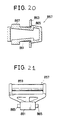
- Figures 18 to 21 show the other modification of the hooks 857 shown in Fig. 10.
- the fitting nails 865 recede in and emerges from both sides of the engaging portion 861 of each hook 857, and operation pieces 867 for causing the recede and emerge of the engaging nails 865 are provided on both sides of the engaging portion 861 of each hook 857.
Abstract
Description
- The present invention relates to a portable blower, and particularly to a portable blower having a vertical rotary shaft which is driven by an engine and provided at its lower end with a fan to blow or suck the dust such as fallen leaves on the ground by the blowing force or the sucking force of the fan.
- In a prior art portable blower, an engine cylinder is horizontally disposed, and, on both sides of the engine cylinder a carburetor and a muffler are arranged respectively. Due to this arrangement, a width of the blower is elongated to bother an operator. For instance, when the blower is hung from a shoulder of the operator by a shoulder belt, the blower will hit the waist or the thigh of the operator to hinder the handling of the blower.
- An air filter is usually disposed at a suction mouth of a fan of the blower to prevent the dust from entering into the blower. In the blower of a type which cools its engine by using a part of air sucked by the fan to blow the dust, the engine tends to overheat if the air filter is clogged by the dust to reduce the airflow.
- Whenever the blower is used for blowing the dust on the ground, a blower pipe shall be attached to the discharge mouth of blower, and the blower pipe shall be removed from the blower and stored every time after the blowing work is finished. This operation of assembling and disassembling of the blower pipe is bothersome in the prior art blower.
- When the blower is used for sucking the dust on the ground, a dust collecting unit shall be attached to the blower. Since the dust collecting unit is relatively bulky and heavy, it is bothersome to handle the dust collecting unit in the prior art blower.
- The portable blower may be used selectively for blowing the dust and for sucking the dust. Whenever the blowing operation and the sucking operation is changed, a blower pipe of the blower shall be changed from a discharge mouth to a suction mouth of the blower or vice versa. This changing operation is bothersome for an operator.
- If an operator wants to blow and suck the dust on the ground simultaneously, the prior art does not provide a suitable blower which can perform conveniently the simultaneous blowing and sucking operation.
- Further, the prior art portable blower is generally provided with projections which are used for hooking a shoulder band. When the shoulder band is not required the projections tend to catch clothes of an operator of the blower to bother the operator.
- In prior art portable blower, an air filter provided for a carburetor is generally attached to and removed from the carburetor in a direction of an airflow, i.e., a direction perpendicular to a plane of the air filter. If it is required in the portable blower to arrange the carburetor above a crankcase and arrange a grip handle over the carburetor, the space for inserting and removing the air filter for the carburetor is very limited to make it difficult to clean or replace the air filter.
- A portable blower in accordance with the preamble of
claim 1 is known from US patent 4461055. This document shows a portable blower comprising an engine chamber and a fan chamber, arranged under the engine chamber. An internal combustion engine is provided having a cylinder extending horizontally and a crankshaft extending vertically into the fan chamber and being connected with the fan wheel. The auxiliary devices for operating the internal combustion engine include a muffler, a carburettor, an air filter, an exhaust, and a tank and are arranged around the internal combustion engine. The housing of the portable blower has two housing parts, separated in an air tight manner from one another. The upper housing part has a cylinder-like base body with a cross-section which is circular to oval in shape and the lower housing part has a rectangular cross-section. - The object of the present invention is to provide a portable blower which is easy to handle by the operator, efficient and reliable in operation and which can be easily assembled and disassembled.
- Another object of the present invention is to provide a portable blower whose hooking portions for hooking a shoulder band do not project outwardly from a body of the blower.
- Another object of the present invention is to provide a portable blower whose air filter for a carburetor can easily be replaced.
- The basic object of the present invention is solved by a portable blower, having the features of
claim 1. Preferred embodiments of the invention are disclosed in the sub-claims. - These and other objects, features and advantages of the present invention will become apparent from the following descriptions of preferred embodiments taken in conjunction with the accompanying drawings in which:
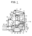
Fig. 1 is a cross-sectional side view showing a portable blower according to a first embodiment of the present invention;
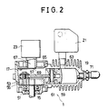
Fig. 2 is an enlarged view showing an engine portion of the blower;
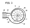
Fig. 3 is a cross-sectional plan view showing a spiral air passage of the blower;
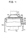
Figs. 4 and 5 are views showing essential portions of the first embodiment;
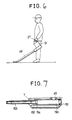
Fig. 6 is a general view showing a portable blower according to a second embodiment of the present invention;
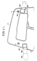
Fig. 7 is a cross-sectional plan view showing an essential portion of a portable blower according to a third embodiment of the present invention;
Figs. 8 and 9 are cross-sectional side views showing essential portions of a portable blower according to a fourth embodiment of the present invention and its modification respectively;
Fig. 10 is a cross-sectional side view showing a portable blower according to a fifth embodiment of the present invention;
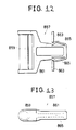
Figs. 11 to 13 are views showing essential portions of the fifth embodiment; and
Figs. 14 to 21 are views showing essential portions of modifications of the fifth embodiment. - The details of the present invention will now be described in the way of embodiments with reference to the drawings. Like numerals represent like parts through the drawings.
- A first embodiment of the present invention will be described with reference to Figs. 1 to 3.
- An
engine 1 is enclosed in anengine casing 3 and ablower fan 5 in afan casing 7 Thecasings casing 13, comprising a right half and a left half which are assembled along a vertical plan including a center line and fixed byscrews 11. Acrankcase 17 has avertical crank shaft 15 and is fixed to anengine cylinder 19 which is arranged at the back of thecrankcase 17. Amuffler 21 is disposed above theengine cylinder 19 and communicates therewith. Acarburetor 23 is disposed above thecrankcase 17 and communicates therewith. Afuel bank 25 having afiller mouth 24 is disposed in front of the engine, inside theengine casing 3. Ahandle 27 is located above thefuel tank 25 and is formed solidly with theengine casing 3. Apartition wall 31 is formed at a bottom of anengine chamber 29 formed in theengine casing 3. Below thepartition wall 31, afan chamber 33 is formed in thefan casing 7. A rotary shaft 32 is connected with thecrank shaft 15 through a centrifugal clutch 30 and extends through thepartition wall 31. A disk-likerotary plate 35 which is provided with theblower fan 5 is fixed to a lower end of the rotary shaft 32 by means of anut 37. Theblower fan 5 comprises a plurality of radial blades formed on a lower surface of therotary plate 35. Anannular wall 39 is fixed to a periphery of therotary plate 35 and extends upwardly. - A
spiral air passage 43 is formed between aperipheral wall 41 of thefan casing 7 and theannular wall 39. Cross-sectional areas of thespiral air passage 43 increase sequentially in a rotational direction of therotary plate 35 as shown in Fig. 3 to communicate with adischarge mouth 45 located at the front of thefan casing 7. In the center of a lower surface of thefan casing 7, asuction mouth 47 is opened. A blower pipe (not shown) will be fitted to thedischarge mouth 45 through aflexible pipe 49. - A constitution of the
engine 1 will be described with reference to Fig. 2. - The
crank shaft 15 is vertically supported by a bearing 51 at a lower part of thecrankcase 17. At an upper end of thecrank shaft 15 in thecrankcase 17, a crank arm 53 is fixed. A crank pin 55 projects upwardly through the crank arm 53 and is connected with one end of apiston rod 57 which is pivotal around the crank pin 55. The other end of thepiston rod 57 is connected with apiston 59, which is freely slidable in theengine cylinder 19, through apiston pin 61. Themuffler 21 is fixed to the upper part ofengine cylinder 19 and communicates with anexhaust port 63 which is located at the upper part ofengine cylinder 19. An upper opening portion of thecrankcase 17 is covered by acap portion 65 through which asuction port 67 extends. Thecarburetor 23 is fixed to thesuction port 67 which is provided at its lower end with acheck valve 69 which opens downwardly. On top of thecylinder 19, anignition plug 71 is provided. - In operation, air is sucked through the
suction mouth 47, sent through thespiral air passage 43 by theblower fan 5, passed through thedischarge mouth 45, and blown from a front end of the blower pipe. An operator will carry thecasing 13 by thehandle 27 with one hand, and the blower pipe with the other hand to blow the dust on the ground to collect the dust. - According to the above arrangement of the present invention, a compact portable blower which does not bother an operator who carries the blower is realized.
- Although the embodiment has been explained as a blower to blow the dust on the ground, it may be used as a dust collector in which a dust collecting case may be attached to the
suction mouth 47 to collect the dust on the ground by using the sucking force ofblower fan 5. - The centrifugal clutch 30 may be omitted, and the
crank shaft 15 can be connected directly to therotary plate 35. - A
choke case 755 incorporating a choke valve (not shown) which is opened and closed by achoke handle 753 is fixed to asuction port 751 which is disposed and opened on an upper surface of thecarburetor 23. Afilter case 757 is formed integrally with theengine casing 3 and can be divided together with theengine casing 3 into a right half and a left half. Thechoke case 755 is supported by thefilter case 757 through arubber buffer pad 759. Anairflow passage 761 communicates with thesuction port 751 through thechoke case 755. A net-likeflat filter 763 is disposed perpendicular to theairflow passage 761 and in thefilter case 757. Thefilter 763 engages with agroove 765 and is removed therefrom by pulling thefilter 763 in a direction perpendicular to theairflow passage 761. - Due to the above arrangement, the
filter 763 can easily be taken out of thefilter case 757 without interfering with thehandle 27, and cleaned. A second embodiment of the present invention will be described with reference to Fig. 6. - A rigid blower pipe 49' instead of the
flexible pipe 49 is removably fitted to thedischarge mouth 45. A front end of the blower pipe 49' is formed such that, when thehandle 27 is carried by a hand, the blower pipe 49' is inclined downwardly, and the front end of blower pipe 49' is horizontal in parallel with the ground. In this using state, the blower is designed such that a couple of force caused around thehandle 27 by a total weight of the blower and a couple of force caused around thehandle 27 by a reaction force of air blown from the end of blower pipe 49' are balanced. Namely, the front end of blower pipe 49' is balanced at a position adjacent to the ground, when thehandle 27 is carried by a hand. - According to the above arrangement, air is blown horizontally out of the end of blower pipe 49' to realize an efficient blowing operation. Even if the ground is soft, the soil will not be blown out by the blowing air, because the air is blown horizontally. It is possible to enlarge a slant angle of the blower pipe 49' being held by a hand to shorten a length of the
blower pipe 49 . A third embodiment will be described with reference to Fig. 7. - A
cylindrical storage chamber 150 is provided besides thefan casing 7. Thedischarge mouth 45 is formed to open at a rear end portion of thestorage chamber 150. Acap 151 is screwed removably to a rear end of thestorage chamber 150. Aconical surface 152 is formed at a front end of thestorage chamber 150. Diameters of theconical surface 152 increase from the front end ofstorage chamber 150 toward the depth ofstorage chamber 150. Ablower pipe 153 is provided at its rear end aconical surface 154 corresponding to theconical surface 152 of thestorage chamber 150. Theblower pipe 153 is stored in thestorage chamber 150 when theblower pipe 153 is not used. To use theblower pipe 153, it is pulled out of thestorage chamber 150, and theconical surfaces - A fourth embodiment of the present invention will be described with reference to Fig. 8. A
blower pipe 200 is connected to thedischarge mouth 45 via a connectingmember 201. The connectingmember 201 is divided along aplane 202 into a fixedportion 203 and apivotal portion 204. Theplane 202 is inclined by 45 degrees. The fixedportion 203 is fixed to a periphery of thedischarge mouth 45. Thepivotal portion 204 is fixed to theblower pipe 200. The fixedportion 203 and thepivotal portion 204 are fitted together bycircular flange portions portions plane 202.Annular members flange portions bolt 209 to hold the fixedportion 204 and thepivotal portion 204 together. In this assembled state, thepivotal portion 204 is pivotal with respect to the fixedportion 203 around aslanted axis 210. Theblower pipe 200 is fixed to thepivotal portion 204 by an angle of 45 degrees with respect to theaxis 210. Theblower pipe 200 can pivot around theaxis 210 from a storing position indicated by a continuous line shown in Fig. 10 to a blowing position indicated by a dotted line shown in the same figure. - Figure 9 shows a modification of the fourth embodiment.
- A cylindrical fixed portion 251 is formed Integrally with the
discharge mouth 45, and a cylindricalpivotal portion 252 is formed integrally with a rear end of ablower pipe 253. An end of thepivotal portion 252 is inserted pivotally into acylindrical end 254 of the fixed portion 251. Ascrew 255 passes through thecylindrical portion 254 and engages with agroove 256 formed on the periphery ofpivotal portion 252 to prevent thepivotal portion 252 from escaping. Theblower pipe 253 can pivot around anaxis 257 from a storing position indicated by a continuous line shown in Fig. 11 to a blowing position indicated by a dotted line shown in the same figure. - A fifth embodiment of the present invention will be described with reference to Figs. 10 to 13. This embodiment relates to hooking portions of a shoulder band of the blower.
- In Fig. 10 the
oil tank 25 is disposed in theengine chamber 29 and in front of theengine 1. Hook holes 851 and 853 are provided at an upper part of theengine casing 3. The hook holes 851 and 853 are opened on the front side and the rear side of theengine casing 3 respectively, and inclined upwardly toward the inside of theengine casing 3.Hooks 857 connected to ashoulder band 855 are inserted into the hook holes 851 and 853 respectively. One end of eachhook 857 is provided with ashaft 859 to which one end of theshoulder band 855 is wound, and the other end of eachhook 857 is provided with an engagingportion 861 which is engaged with thehole portion 861, there are provided engagingnails 865 which project outwardly and engage removably with engagingportions 863 which are formed inside theholes engaging nail 865 are slanted. - When the
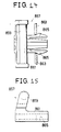
shoulder band 855 is not required, thehooks 857 are pulled strongly out of the hook holes 851 and 853 such that the slanted faces of engagingnails 865 are pressed by the engagingportions 863 to remove the engagingnails 865 from the engagingportions 863. When theshoulder band 855 is required, thehooks 857 are are strongly inserted into the hook holes 851 and 853 respectively such that the slanted faces of the engagingnails 865 are pressed against the engagingportions 863 to engage the engagingnails 865 with the engagingportions 863. - Figures 14 and 15 show a modification of the
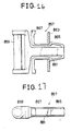
hooks 857 shown in Fig. 10. In this modification, thehooks 857 are bent upwardly, and theshafts 59 are positioned at the upper part of thehooks 857. - Figures 16 and 17 show another modification of the
hooks 857 shown in Fig. 10. In this modification,operation pieces 867 for engaging and releasing the engagingnails 865 are provided on both sides of the engagingportion 861 of eachhook 857. - Figures 18 to 21 show the other modification of the
hooks 857 shown in Fig. 10. In this modification, thefitting nails 865 recede in and emerges from both sides of the engagingportion 861 of eachhook 857, andoperation pieces 867 for causing the recede and emerge of the engagingnails 865 are provided on both sides of the engagingportion 861 of eachhook 857. - According to the above arrangements shown in Figs. 11 to 21, the
shoulder band 855 will easily be attached to or removed from the blower. When theshoulder band 855 is removed from the blower, the blower has no projecting hooks so that the blower will not catch the clothes, etc., of an operator of the blower.
Claims (12)
- A portable blower comprising:
a casing (13) provided with a handle (27) and including an engine chamber (3) and a fan chamber (7), said fan chamber (7) being arranged under said engine chamber with a partition wall (31) between them and having a suction mouth (47) with an air passage (43) connecting said suction mouth with the fan chamber, and a discharge mouth (45);
a fuel tank (25) arranged within said engine chamber (3), an engine (1) having a cylinder (19) extending horizontally, a crankcase (17) disposed in front of said cylinder (19) and connected thereto, a cantilever-type crankshaft (15) extending vertically from the crankcase (17) of the engine into said fan chamber (7) through said partition wall (31), a carburetor (23) and a muffler (21) arranged within said engine chamber (3);
a fanwheel (5) provided within this the fan chamber, said fanwheel being connected to the crankshaft (15);
characterized in that
said casing comprises a right half portion and a left half portion which are assembled and disassembled along a vertical plane, including a vertical centre axis of the crankshaft (15);
that the crankcase (17), the cylinder (19), the carburetor (23), the muffler (21) and the fuel tank (25) are arranged essentially in the same vertical plane (9);
that the carburetor (23) is disposed above said crankcase (17) and connected thereto and the muffler (21) is arranged above said cylinder (19) and connected thereo and that said fuel tank (25) is arranged in front of said cylinder (19). - A portable blower as claimed in claim 1, wherein said air passage is formed in a spiral air passage (43) which cross-sectional areas are sequentially increased toward said discharge mouth and wherein said blower fan comprises a disk-like rotary plate (35) fixed to the lower end of said crank shaft (15) a periphery of said rotary plate extending upwardly, and a plurality of blades formed radially on a lower surface of said rotary plate.
- A portable blower as claimed in claimed 1, comprising further a rigid blower pipe (49') connected to said discharge mouth (45) in which, when the blower is carried by said handle, a couple of force caused around said handle (27) by a total weight of said blower and a couple of force caused around the handle (27) by a reaction force of air blown from a front end of said blower pipe are balanced to keep said front end of the blower pipe horizontal in parallel with the ground.
- A portable blower as claimed in claim 3, comprising further:
a cylindrical storage chamber (150) adjoining said fan chamber (7a) diameter of said cylindrical storage chamber being slightly larger than said blower pipe (153) and said discharge mouth (45) being formed on a wall of said cylindrical storage chamber;
a cap (151) screwed removably to a rear end of said cylindrical storage chamber (150) and
a conical inner surface (154) formed at a front end of said cylindrical storage chamber,
wherein said blower pipe (153) has a conical rear end corresponding to said conical inner surface and is stored in said cylindrical storage chamber (150) said conical rear end of said blower pipe being engaged tightly with said conical inner surface when said blower pipe is pulled out of said cylindrical storage chamber. - A portable blower as claimed in claim 4, comprising further a connecting member (201) which comprises:
a fixed portion (203) having a flange and fixed to said discharge mouth;
a pivotal portion (204) having a flange and fixed to a rear end of said blower pipe;
an annular member (207,208) to be disposed around said flanges of said fixed and pivotal portions,
wherein said fixed portion and said pivotal portion are held together by fitting said flanges to each other, and by arranging said annular member around said flanges, and, in this held state, said pivotal portion can pivot with respect to said fixed portion such that said blower pipe will move from a vetical position where a front end of said blower pipe faces upward to a horizontal position, or from the horizontal position to the vertical position. - A portable blower as claimed in claim 5, wherein each of said fixed portion and said pivotal portion is formed in a hemispheric shape.
- A portable blower as claimed in claim 6, wherein each of said fixed portion and said pivotal portion is formed in a cylindrical shape.
- A portable blower as claimed in claim 1, comprising further an air filter (763) for said carburetor (23), said air filter being fitted to and removed from a suction port of said carburetor in a direction perpendicular to an airflow passage (761) which passes through said suction port (751) of the carburetor (23).
- A portable blower as claimed in claim 1, comprising further:
a pair of hook hollows (851,853) formed at upper front and upper rear portions of said casing respectively, said hook hollows being slanted upwardly starting from said upper front and upper rear portions respectively, and provided with engaging portions therein respectively;
a shoulder band (855); and
a pair of hooks (857) attached to both ends of said shoulder band respectively and removably inserted into a pair of said hook hollows respectively, each of said hooks comprising:
a hook body member;
a hooking shaft (859) disposed at one end of said hook body member for fixing one end of said shoulder band; and
nails (865) disposed on both sides at the other end of said hook body member and projecting outwardly to be engaged removably with said engaging potion (863) of said hook hollow. - A portable blower as claimed in claim 9, wherein said hook body members are bent upwardly, and said hooking shafts being disposed at upper ends of said bent hook body members respectively.
- A portable blower as claimed in claim 10, comprising further a pair of operation pieces (867) provided on both sides of each hook body member, said operation pieces being operated by fingers to engage and release said nails (865) with respect to said engaging portion of said hook hollow.
- A portable blower as claimed in claim 11, wherein said nails (865) can recede in and emerge from said hook body member, and said operation pieces (867) are operated by fingers to cause the recede and the emerge of said nails.
Applications Claiming Priority (7)
| Application Number | Priority Date | Filing Date | Title |
|---|---|---|---|
| JP104026/85 | 1985-07-10 | ||
| JP104027/85 | 1985-07-10 | ||
| JP10402885U JPH0310178Y2 (en) | 1985-07-10 | 1985-07-10 | |
| JP104028/85 | 1985-07-10 | ||
| JP10402685U JPH0310176Y2 (en) | 1985-07-10 | 1985-07-10 | |
| JP10402785U JPH0310177Y2 (en) | 1985-07-10 | 1985-07-10 | |
| EP86109449A EP0208320B1 (en) | 1985-07-10 | 1986-07-10 | Portable blower |
Related Parent Applications (1)
| Application Number | Title | Priority Date | Filing Date |
|---|---|---|---|
| EP86109449.8 Division | 1986-07-10 |
Publications (3)
| Publication Number | Publication Date |
|---|---|
| EP0422701A2 true EP0422701A2 (en) | 1991-04-17 |
| EP0422701A3 EP0422701A3 (en) | 1991-07-17 |
| EP0422701B1 EP0422701B1 (en) | 1994-06-29 |
Family
ID=27310129
Family Applications (2)
| Application Number | Title | Priority Date | Filing Date |
|---|---|---|---|
| EP86109449A Expired - Lifetime EP0208320B1 (en) | 1985-07-10 | 1986-07-10 | Portable blower |
| EP90125781A Expired - Lifetime EP0422701B1 (en) | 1985-07-10 | 1986-07-10 | Portable blower |
Family Applications Before (1)
| Application Number | Title | Priority Date | Filing Date |
|---|---|---|---|
| EP86109449A Expired - Lifetime EP0208320B1 (en) | 1985-07-10 | 1986-07-10 | Portable blower |
Country Status (4)
| Country | Link |
|---|---|
| US (2) | US4723893A (en) |
| EP (2) | EP0208320B1 (en) |
| AU (1) | AU580680B2 (en) |
| DE (2) | DE3681836D1 (en) |
Cited By (1)
| Publication number | Priority date | Publication date | Assignee | Title |
|---|---|---|---|---|
| DE29507709U1 (en) * | 1995-05-15 | 1995-07-06 | Elektra Beckum Ag | Suction / blower |
Families Citing this family (29)
| Publication number | Priority date | Publication date | Assignee | Title |
|---|---|---|---|---|
| US4870714A (en) * | 1987-11-09 | 1989-10-03 | Black & Decker Inc. | Portable blower/vacuum system |
| US5269665A (en) * | 1989-04-19 | 1993-12-14 | White Consolidated Industries, Inc. | Portable hand-held blower/vacuum unit with resilient engine mounting system |
| US5035586A (en) * | 1989-04-19 | 1991-07-30 | White Consolidated Industries, Inc. | Portable hand-held blower/vacuum unit with resilient engine mounting system |
| JP2948954B2 (en) * | 1991-09-19 | 1999-09-13 | 株式会社共立 | Engine driven blower |
| JP2558617Y2 (en) * | 1993-02-05 | 1997-12-24 | 株式会社共立 | Handheld cleaner |
| GB2302368B (en) * | 1993-07-19 | 1997-09-03 | Wci Outdoor Products Inc | Two cycle air-cooled uniflow gasolene engine for powering a portable tool |
| US5584436A (en) * | 1994-11-18 | 1996-12-17 | White Consolidated Industires, Inc. | Portable blower with detachable nozzle |
| US5560078A (en) * | 1995-05-04 | 1996-10-01 | The Toro Company | Portable Blower/Vac |
| US5692262A (en) * | 1996-01-22 | 1997-12-02 | Haupt; David J. | Mulching impeller for lawn and garden mulching blower-vacuum |
| US6059541A (en) * | 1998-03-10 | 2000-05-09 | The Toro Company | Air inlet cover for portable blower/vacuum |
| US6132178A (en) * | 1998-03-16 | 2000-10-17 | Carter; Lonnie G. | Hand held pump device |
| US6125503A (en) * | 1998-05-12 | 2000-10-03 | Az-Tech Research And Development Corporation | Retracting rotational backpack blower air discharge tube unit |
| SE515429C2 (en) * | 1999-12-03 | 2001-08-06 | Electrolux Ab | Leaf Blowers |
| US6305909B1 (en) | 2000-02-25 | 2001-10-23 | Mtd Southwest Inc. | Engine arrangement for blowers and blower/vacuums |
| US6629818B2 (en) | 2001-02-09 | 2003-10-07 | The Toro Company | Impeller for use with portable blower/vacuums |
| EP1744804A4 (en) * | 2004-05-03 | 2009-11-04 | Fulfillium Inc | Method and system for gastric volume control |
| US8070807B2 (en) | 2004-11-19 | 2011-12-06 | Fulfillium, Inc. | Wireless breach detection |
| US9456915B2 (en) | 2004-11-19 | 2016-10-04 | Fulfilium, Inc. | Methods, devices, and systems for obesity treatment |
| US20080109027A1 (en) * | 2006-08-01 | 2008-05-08 | Fulfillium, Inc. | Method and system for gastric volume control |
| JP4866676B2 (en) * | 2006-08-08 | 2012-02-01 | ハスクバーナ・ゼノア株式会社 | Engine blower |
| US20080152487A1 (en) * | 2006-12-22 | 2008-06-26 | Shaffer Chadwick A | Portable blower/vacuum and impeller for use with same |
| US20090238687A1 (en) * | 2008-03-21 | 2009-09-24 | Jen-Wei Lin | Blower |
| US7870640B2 (en) * | 2008-03-31 | 2011-01-18 | The Toro Company | Convertible blower/vacuum |
| JP5620690B2 (en) * | 2010-02-15 | 2014-11-05 | 株式会社マキタ | Blower |
| JP5572060B2 (en) * | 2010-10-22 | 2014-08-13 | 株式会社やまびこ | Air blower |
| US8963708B2 (en) | 2011-01-13 | 2015-02-24 | Sensurtec, Inc. | Breach detection in solid structures |
| US10039367B2 (en) | 2015-05-25 | 2018-08-07 | Chevron (Hk) Limited | Back-mounted power tool systems and methods of use |
| US10064527B2 (en) * | 2016-10-05 | 2018-09-04 | Jose L. Mata | Leaf blower vacuum yard cart |
| JP7108443B2 (en) * | 2018-03-30 | 2022-07-28 | 株式会社マキタ | air blower |
Citations (2)
| Publication number | Priority date | Publication date | Assignee | Title |
|---|---|---|---|---|
| US4288886A (en) * | 1979-08-23 | 1981-09-15 | Frederick Siegler | Air broom |
| US4461055A (en) * | 1981-07-01 | 1984-07-24 | Andreas Stihl | Portable sweeping device |
Family Cites Families (17)
| Publication number | Priority date | Publication date | Assignee | Title |
|---|---|---|---|---|
| US1606424A (en) * | 1924-04-03 | 1926-11-09 | Johnson Bros Engineering Corp | Oiling system for gas engines |
| US2284141A (en) * | 1940-07-25 | 1942-05-26 | Advance Aluminum Castings Corp | Suction fan unit |
| US2529362A (en) * | 1946-01-25 | 1950-11-07 | Stewart Warner Corp | Blower |
| US3037582A (en) * | 1961-04-13 | 1962-06-05 | Goodall Mfg Corp | Combination oil reservoir and bearing mount for internal combustion engines |
| US3829250A (en) * | 1971-09-22 | 1974-08-13 | Torin Corp | Blower assembly |
| JPS5419562A (en) * | 1977-07-13 | 1979-02-14 | Shikutani Kk | Blow cleaner |
| JPS6129778Y2 (en) * | 1978-02-15 | 1986-09-02 | ||
| US4211058A (en) * | 1978-08-14 | 1980-07-08 | Outboard Marine Corporation | Lawn mower including a carburetor enclosure |
| IT1164933B (en) * | 1979-02-08 | 1987-04-15 | Aspera Spa | MOTOPOMPA |
| JPS5628787U (en) * | 1979-08-10 | 1981-03-18 | ||
| US4269571A (en) * | 1979-08-14 | 1981-05-26 | Kabushiki Kaisha Shikutani | Blowing apparatus |
| US4413371A (en) * | 1981-06-29 | 1983-11-08 | Emerson Electric Co. | Blower attachment for portable power unit |
| JPS5915633A (en) * | 1982-07-20 | 1984-01-26 | Yamaha Motor Co Ltd | Small-size engine driven generator |
| US4451951A (en) * | 1982-09-15 | 1984-06-05 | Kioritz Corporation | Engine-driven blower/dust collector |
| JPS5970838A (en) * | 1982-10-15 | 1984-04-21 | Honda Motor Co Ltd | Vertical internal-combustion engine for general use |
| GB8318528D0 (en) * | 1983-07-08 | 1983-08-10 | Rotork Appliances Ltd | Vacuum suction cleaning appliances |
| JPS6122826A (en) * | 1984-07-11 | 1986-01-31 | 小松ゼノア株式会社 | Dust collection apparatus |
-
1986
- 1986-07-07 US US06/882,590 patent/US4723893A/en not_active Expired - Lifetime
- 1986-07-09 AU AU59892/86A patent/AU580680B2/en not_active Ceased
- 1986-07-10 DE DE8686109449T patent/DE3681836D1/en not_active Expired - Fee Related
- 1986-07-10 EP EP86109449A patent/EP0208320B1/en not_active Expired - Lifetime
- 1986-07-10 EP EP90125781A patent/EP0422701B1/en not_active Expired - Lifetime
- 1986-07-10 DE DE3689942T patent/DE3689942T2/en not_active Expired - Fee Related
-
1987
- 1987-07-27 US US07/078,401 patent/US4746274A/en not_active Expired - Lifetime
Patent Citations (2)
| Publication number | Priority date | Publication date | Assignee | Title |
|---|---|---|---|---|
| US4288886A (en) * | 1979-08-23 | 1981-09-15 | Frederick Siegler | Air broom |
| US4461055A (en) * | 1981-07-01 | 1984-07-24 | Andreas Stihl | Portable sweeping device |
Cited By (1)
| Publication number | Priority date | Publication date | Assignee | Title |
|---|---|---|---|---|
| DE29507709U1 (en) * | 1995-05-15 | 1995-07-06 | Elektra Beckum Ag | Suction / blower |
Also Published As
| Publication number | Publication date |
|---|---|
| AU5989286A (en) | 1987-01-15 |
| DE3681836D1 (en) | 1991-11-14 |
| DE3689942T2 (en) | 1994-10-13 |
| EP0208320B1 (en) | 1991-10-09 |
| EP0208320A2 (en) | 1987-01-14 |
| US4746274A (en) | 1988-05-24 |
| EP0422701B1 (en) | 1994-06-29 |
| EP0208320A3 (en) | 1988-01-07 |
| US4723893A (en) | 1988-02-09 |
| AU580680B2 (en) | 1989-01-27 |
| DE3689942D1 (en) | 1994-08-04 |
| EP0422701A3 (en) | 1991-07-17 |
Similar Documents
| Publication | Publication Date | Title |
|---|---|---|
| EP0422701B1 (en) | Portable blower | |
| US5035586A (en) | Portable hand-held blower/vacuum unit with resilient engine mounting system | |
| US5269665A (en) | Portable hand-held blower/vacuum unit with resilient engine mounting system | |
| US4318203A (en) | Single-handed operation type scavenging blower | |
| US4674146A (en) | Hand held gas engine blower | |
| US4132507A (en) | Blowing apparatus | |
| JP3665220B2 (en) | Portable power work machine | |
| US5542380A (en) | Integrated dynamic air cleaner | |
| USRE33050E (en) | Hand held gas engine blower | |
| US5345684A (en) | Flexible line trimmer having an anti-vibration handle | |
| US7007660B2 (en) | Portable power working machine | |
| US6994070B2 (en) | Portable air blowing working machine | |
| MX2008002659A (en) | Portable, compact pneumatic suction cleaner with means for low noise operation. | |
| US4813385A (en) | General-purpose internal combustion engine | |
| US5457846A (en) | Portable power blower | |
| US6250882B1 (en) | Portable working machine provided with a centrifugal air blower | |
| US6213066B1 (en) | Drive unit | |
| US6305909B1 (en) | Engine arrangement for blowers and blower/vacuums | |
| US6464018B1 (en) | Portable handheld drilling machine having an internal combustion engine | |
| JPH0310176Y2 (en) | ||
| JPH0310177Y2 (en) | ||
| JPH0510894Y2 (en) | ||
| WO2022190383A1 (en) | Internal combustion engine | |
| JPH0125919B2 (en) | ||
| JPH0490Y2 (en) |
Legal Events
| Date | Code | Title | Description |
|---|---|---|---|
| PUAI | Public reference made under article 153(3) epc to a published international application that has entered the european phase |
Free format text: ORIGINAL CODE: 0009012 |
|
| 17P | Request for examination filed |
Effective date: 19901228 |
|
| AC | Divisional application: reference to earlier application |
Ref document number: 208320 Country of ref document: EP |
|
| AK | Designated contracting states |
Kind code of ref document: A2 Designated state(s): DE FR GB |
|
| PUAL | Search report despatched |
Free format text: ORIGINAL CODE: 0009013 |
|
| AK | Designated contracting states |
Kind code of ref document: A3 Designated state(s): DE FR GB |
|
| 17Q | First examination report despatched |
Effective date: 19930712 |
|
| GRAA | (expected) grant |
Free format text: ORIGINAL CODE: 0009210 |
|
| AC | Divisional application: reference to earlier application |
Ref document number: 208320 Country of ref document: EP |
|
| AK | Designated contracting states |
Kind code of ref document: B1 Designated state(s): DE FR GB |
|
| PGFP | Annual fee paid to national office [announced via postgrant information from national office to epo] |
Ref country code: GB Payment date: 19940629 Year of fee payment: 9 |
|
| PGFP | Annual fee paid to national office [announced via postgrant information from national office to epo] |
Ref country code: FR Payment date: 19940705 Year of fee payment: 9 |
|
| REF | Corresponds to: |
Ref document number: 3689942 Country of ref document: DE Date of ref document: 19940804 |
|
| ET | Fr: translation filed | ||
| PLBE | No opposition filed within time limit |
Free format text: ORIGINAL CODE: 0009261 |
|
| STAA | Information on the status of an ep patent application or granted ep patent |
Free format text: STATUS: NO OPPOSITION FILED WITHIN TIME LIMIT |
|
| 26N | No opposition filed | ||
| PG25 | Lapsed in a contracting state [announced via postgrant information from national office to epo] |
Ref country code: GB Effective date: 19950710 |
|
| PGFP | Annual fee paid to national office [announced via postgrant information from national office to epo] |
Ref country code: DE Payment date: 19950831 Year of fee payment: 10 |
|
| GBPC | Gb: european patent ceased through non-payment of renewal fee |
Effective date: 19950710 |
|
| PG25 | Lapsed in a contracting state [announced via postgrant information from national office to epo] |
Ref country code: FR Effective date: 19960430 |
|
| REG | Reference to a national code |
Ref country code: FR Ref legal event code: ST |
|
| REG | Reference to a national code |
Ref country code: FR Ref legal event code: ST |
|
| REG | Reference to a national code |
Ref country code: FR Ref legal event code: ST |
|
| PG25 | Lapsed in a contracting state [announced via postgrant information from national office to epo] |
Ref country code: DE Effective date: 19970402 |