EP0416792A2 - Access control devices and systems incorporating such devices - Google Patents
Access control devices and systems incorporating such devices Download PDFInfo
- Publication number
- EP0416792A2 EP0416792A2 EP90309364A EP90309364A EP0416792A2 EP 0416792 A2 EP0416792 A2 EP 0416792A2 EP 90309364 A EP90309364 A EP 90309364A EP 90309364 A EP90309364 A EP 90309364A EP 0416792 A2 EP0416792 A2 EP 0416792A2
- Authority
- EP
- European Patent Office
- Prior art keywords
- access
- access control
- code
- signal
- devices
- Prior art date
- Legal status (The legal status is an assumption and is not a legal conclusion. Google has not performed a legal analysis and makes no representation as to the accuracy of the status listed.)
- Withdrawn
Links
Images


Classifications
-
- G—PHYSICS
- G08—SIGNALLING
- G08B—SIGNALLING OR CALLING SYSTEMS; ORDER TELEGRAPHS; ALARM SYSTEMS
- G08B5/00—Visible signalling systems, e.g. personal calling systems, remote indication of seats occupied
- G08B5/22—Visible signalling systems, e.g. personal calling systems, remote indication of seats occupied using electric transmission; using electromagnetic transmission
- G08B5/222—Personal calling arrangements or devices, i.e. paging systems
- G08B5/223—Personal calling arrangements or devices, i.e. paging systems using wireless transmission
- G08B5/224—Paging receivers with visible signalling details
- G08B5/229—Paging receivers with visible signalling details with other provisions not elsewhere provided for
-
- G—PHYSICS
- G07—CHECKING-DEVICES
- G07C—TIME OR ATTENDANCE REGISTERS; REGISTERING OR INDICATING THE WORKING OF MACHINES; GENERATING RANDOM NUMBERS; VOTING OR LOTTERY APPARATUS; ARRANGEMENTS, SYSTEMS OR APPARATUS FOR CHECKING NOT PROVIDED FOR ELSEWHERE
- G07C9/00—Individual registration on entry or exit
- G07C9/00174—Electronically operated locks; Circuits therefor; Nonmechanical keys therefor, e.g. passive or active electrical keys or other data carriers without mechanical keys
- G07C9/00309—Electronically operated locks; Circuits therefor; Nonmechanical keys therefor, e.g. passive or active electrical keys or other data carriers without mechanical keys operated with bidirectional data transmission between data carrier and locks
-
- G—PHYSICS
- G07—CHECKING-DEVICES
- G07C—TIME OR ATTENDANCE REGISTERS; REGISTERING OR INDICATING THE WORKING OF MACHINES; GENERATING RANDOM NUMBERS; VOTING OR LOTTERY APPARATUS; ARRANGEMENTS, SYSTEMS OR APPARATUS FOR CHECKING NOT PROVIDED FOR ELSEWHERE
- G07C9/00—Individual registration on entry or exit
- G07C9/00174—Electronically operated locks; Circuits therefor; Nonmechanical keys therefor, e.g. passive or active electrical keys or other data carriers without mechanical keys
- G07C9/00896—Electronically operated locks; Circuits therefor; Nonmechanical keys therefor, e.g. passive or active electrical keys or other data carriers without mechanical keys specially adapted for particular uses
- G07C9/00904—Electronically operated locks; Circuits therefor; Nonmechanical keys therefor, e.g. passive or active electrical keys or other data carriers without mechanical keys specially adapted for particular uses for hotels, motels, office buildings or the like
-
- G—PHYSICS
- G07—CHECKING-DEVICES
- G07C—TIME OR ATTENDANCE REGISTERS; REGISTERING OR INDICATING THE WORKING OF MACHINES; GENERATING RANDOM NUMBERS; VOTING OR LOTTERY APPARATUS; ARRANGEMENTS, SYSTEMS OR APPARATUS FOR CHECKING NOT PROVIDED FOR ELSEWHERE
- G07C9/00—Individual registration on entry or exit
- G07C9/20—Individual registration on entry or exit involving the use of a pass
- G07C9/28—Individual registration on entry or exit involving the use of a pass the pass enabling tracking or indicating presence
-
- G—PHYSICS
- G07—CHECKING-DEVICES
- G07C—TIME OR ATTENDANCE REGISTERS; REGISTERING OR INDICATING THE WORKING OF MACHINES; GENERATING RANDOM NUMBERS; VOTING OR LOTTERY APPARATUS; ARRANGEMENTS, SYSTEMS OR APPARATUS FOR CHECKING NOT PROVIDED FOR ELSEWHERE
- G07C9/00—Individual registration on entry or exit
- G07C9/20—Individual registration on entry or exit involving the use of a pass
- G07C9/29—Individual registration on entry or exit involving the use of a pass the pass containing active electronic elements, e.g. smartcards
-
- G—PHYSICS
- G08—SIGNALLING
- G08B—SIGNALLING OR CALLING SYSTEMS; ORDER TELEGRAPHS; ALARM SYSTEMS
- G08B3/00—Audible signalling systems; Audible personal calling systems
- G08B3/10—Audible signalling systems; Audible personal calling systems using electric transmission; using electromagnetic transmission
- G08B3/1008—Personal calling arrangements or devices, i.e. paging systems
- G08B3/1016—Personal calling arrangements or devices, i.e. paging systems using wireless transmission
- G08B3/1025—Paging receivers with audible signalling details
- G08B3/1066—Paging receivers with audible signalling details with other provisions not elsewhere provided for, e.g. turn-off protection
-
- G—PHYSICS
- G07—CHECKING-DEVICES
- G07C—TIME OR ATTENDANCE REGISTERS; REGISTERING OR INDICATING THE WORKING OF MACHINES; GENERATING RANDOM NUMBERS; VOTING OR LOTTERY APPARATUS; ARRANGEMENTS, SYSTEMS OR APPARATUS FOR CHECKING NOT PROVIDED FOR ELSEWHERE
- G07C9/00—Individual registration on entry or exit
- G07C9/00174—Electronically operated locks; Circuits therefor; Nonmechanical keys therefor, e.g. passive or active electrical keys or other data carriers without mechanical keys
- G07C2009/00753—Electronically operated locks; Circuits therefor; Nonmechanical keys therefor, e.g. passive or active electrical keys or other data carriers without mechanical keys operated by active electrical keys
- G07C2009/00769—Electronically operated locks; Circuits therefor; Nonmechanical keys therefor, e.g. passive or active electrical keys or other data carriers without mechanical keys operated by active electrical keys with data transmission performed by wireless means
- G07C2009/00793—Electronically operated locks; Circuits therefor; Nonmechanical keys therefor, e.g. passive or active electrical keys or other data carriers without mechanical keys operated by active electrical keys with data transmission performed by wireless means by Hertzian waves
-
- G—PHYSICS
- G07—CHECKING-DEVICES
- G07C—TIME OR ATTENDANCE REGISTERS; REGISTERING OR INDICATING THE WORKING OF MACHINES; GENERATING RANDOM NUMBERS; VOTING OR LOTTERY APPARATUS; ARRANGEMENTS, SYSTEMS OR APPARATUS FOR CHECKING NOT PROVIDED FOR ELSEWHERE
- G07C9/00—Individual registration on entry or exit
- G07C9/00174—Electronically operated locks; Circuits therefor; Nonmechanical keys therefor, e.g. passive or active electrical keys or other data carriers without mechanical keys
- G07C9/00817—Electronically operated locks; Circuits therefor; Nonmechanical keys therefor, e.g. passive or active electrical keys or other data carriers without mechanical keys where the code of the lock can be programmed
- G07C2009/00825—Electronically operated locks; Circuits therefor; Nonmechanical keys therefor, e.g. passive or active electrical keys or other data carriers without mechanical keys where the code of the lock can be programmed remotely by lines or wireless communication
Definitions
- This invention relates to access control devices sand to systems incorporating such devices. It is particularly applicable to such devices and systems for use within hotel environments, commercial and financial offices and industrial complexes.
- Security is an increasing problem in every walk of life and is particularly acute within the hotel industry.
- Theft can be in the form of property stolen from hotel bedrooms or it can be in the form of unauthorised and unpaid usage of hotel facilities such as gymnasiums, saunas, swimming pools.
- Theft can even take the form of unauthorised consumption of food and drink by non-registered guests.
- Increased security in the form of access control can therefore readily provide benefits for both guest and hotel operator alike. The guests gain from added security, whilst the operator gains from reduced levels of fraud.
- Electro-mechanical programmable door locks represent important elements of access control systems and are being installed in increasing numbers, particularly in high technology hotels which cater for the international business traveller. Whenever a new guest registers in one of these hotels he may be allocated a unique 'key' which is coded and can only be used to operate the lock controlling access to his room - and then only during the period of his stay.
- the 'key' may be constructed from a thin strip of card or plastic or from a laminated hybrid structure.
- Lock code changes are routinely carried out by a member of the hotel staff physically reprogramming the lock mechanisms - usually during or after room preparation. This process is often achieved by the insertion of a two part coded card into the door lock mechanism - one part of the card, containing the new code, being snapped off and left within the lock mechanism, whilst the other part, the 'key', is removed and deposited with hotel check-in staff. The 'key' is then issued to the guest who is allocated the room with the matching coded lock.
- the door lock is reprogrammed with another two part coded card and the 'key' portion is once more issued to the guest.
- the door lock allowing access to the room in which the guest stayed is once again reprogrammed.
- the old 'key' is either discarded or retained by the guest as a souvenir.
- Lock codes are normally written on a magnetic strip printed or attached by some means onto the surface of the 'key', although it will be appreciated that the same code may be electronically or optically stored within the body of the 'key' or even stored in the form of physical holes or deformations on part of the 'key'.
- an access control device which is programmable to allow access to a restricted access area, characterised by pager means which is formed as part of said device for receiving a transmitted paging signal.
- said device will take the form of an electronic 'smart' card, which conveniently comprises means for affording an audible or visual indication when a paging signal has been received.
- a received paging signal may be represented by illuminating a light adjacent or near to text which is descriptive of the intended message of the received paging signal, or an alpha-numeric display may be provided for displaying a received paging signal.
- the access control device is programmed with an electronic, magnetic, optical, mechanical or electrical code to allow access to a restricted access area.
- the access control device will include a transponding arrangement for receiving an interrogation signal and for transponding a predetermined code when an interrogation signal has been received to allow access to a restricted access area.
- said access control device may be programmed with a paging code which determines the paging signals which are receivable by said device, and said device may be adapted to be used as an electronic data transfer device e.g. for electronic credit, charge card or data bank purposes.
- an access control system comprising a plurality of access control devices according to the aforesaid first aspect of the present invention and further comprising coding means for programming each of said access control devices with an access code to allow access to a specified restricted access area, further coding means for programming each specified restricted access area with an access code which corresponds to the access code of one or more of said access control devices, and means for transmitting a coded paging signal to one or more of said access control devices.
- a programmable security device will be provided for restricting access to each specified restricted access area, said further coding means being effective for programming each programmable security device with an access code, each of said programmable security devices being responsive to one or more access control devices having the same code for allowing access to the specified restricted area thereof.
- each programmable security device comprises means for transmitting an interrogating signal when it is actuated, and means for receiving a transponded signal from an access control device which is in receipt of said interrogating signal, said programmable security device being responsive to a transponded signal from an access control device having the same access with which it is programmed for allowing access to the restricted access area thereof.
- said programmable security devices are programmed manually or are programmed remotely, in which case a signal may be transmitted to said programmable security devices for programming each said programmable security device with its access code.
- said access control devices constitute room key devices which are programmed with an access code which is also programmed into an electronic door lock associated with a specified room of said hotel to allow access to said room when the access code of said access control device corresponds to the access code of said electronic door lock, means being provided for transmitting a coded paging signal to one or more of said access control devices.
- the invention is based on the use of an access control device in the form of an electronic 'key' which incorporates a 'pager' which may be used to make contact with the person who has possession of the 'key'.
- an electronic 'key' which incorporates a 'pager' which may be used to make contact with the person who has possession of the 'key'.
- the electronic 'key' incorporating the pager will be referred to as a 'PAGEKEY'.
- the access control system which is to be described is based on the use of a programmable door lock mechanism which is fitted to each of the hotel rooms, each of the door lock mechanisms being programmed with a unique code such that it can only be opened, to gain access to the room, by a 'PAGEKEY' which is coded with the same unique code.
- Each 'PAGEKEY' is provided with a paging facility for receiving a transmitted paging signal which is used to contact the person in possession of the 'PAGEKEY'.
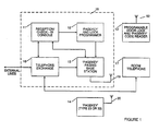
- FIG. 1 of the drawings there is shown a hotel access control system which comprises a control unit 18, which is typically located on or near the hotel reception desk.
- a control unit 18 which is typically located on or near the hotel reception desk.
- Each of the rooms of the hotel is fitted with a programmable door lock mechanism 13 and a room telephone 17, and each guest of the hotel is provided with a 'PAGEKEY' 14.
- the control unit 18 comprises a reception check-in console 11 which is interconnected with the hotel telephone exchange 16, a 'PAGEKEY' and lock programmer 12, and a 'PAGEKEY' paging base station 15.
- the receptionist When a new guest checks into the hotel, the receptionist identifies a suitable room for the guest via the check-in console 11 which also generates a suitable code which is to be allocated to that particular room for the period that the room is to be allocated to the new guest.
- the code generated by check-in console 11 is fed to the 'PAGEKEY' and lock programmer 12 into which is inserted the 'PAGEKEY' 14 which is to be allocated to the new guest.
- the 'PAGEKEY' and lock programmer 12 codes the 'PAGEKEY' 14 with the required code and the code is also fed to the 'PAGEKEY' paging base station 15 where it is transmitted via aerial 19 to the programmable door lock mechanism 13, via its aerial 52, of the room which has been allocated to the new guest.
- the coded 'PAGEKEY' is then issued to the new guest which enables them to gain access only to the room which has been allocated to them.
- Other areas of the hotel which are provided only for the benefit of hotel guests, such as gymnasiums, saunas, swimming pools, etc. may also be provided with programmable door lock mechanisms 13, which are programmed such that any guest having a valid 'PAGEKEY' can gain access thereto.
- a coded paging signal is transmitted by the 'PAGEKEY' paging and base station 15, via its aerial 19, to the appropriately coded 'PAGEKEY' lin, via its aerial 20.
- the hotel receptionist can make direct contact with any required hotel guest. It may also be arranged that when a telephone call is received for a hotel guest, when the call is transferred to the guest's room telephone, if the guest is absent and unable to answer the call, it may be arranged that a paging signal is transmitted to the 'PAGEKEY' of the hotel guest in question who will then know that contact should be made to the hotel reception.
- the paging signal which is transmitted to the 'PAGEKEY' 14 by the 'PAGEKEY' paging base station 15 of Figure 1 may take a variety of different forms.
- Radio page receivers are finding widespread use throughout the world and are currently classified into two types. Firstly, there is the type which only generates an attention getting tone or flashes a light emitting diode (LED) on reception and identification of an appropriate call code. For the purposes of this invention this receiver will be called a tone-only type of receiver.
- the second type of receiver can display a variety of messages in addition to the generation of an audible tone and will be called a receiver of the display type.
- paging system There are also different types of paging system which provide varying degrees of coverage. For example, some systems provide paging coverage over typically several hundred miles or more, whilst other systems hereafter referred to as local area paging systems, provide coverage restricted to defined areas such as industrial or commercial premises. Of particular relevance to this invention is the local area paging system which may use electromagnetic radiation, inductive pick-up, ultrasonic or infra-red radiation as a means of data communication between base station and receiver and in some cases between receiver and base station.
- a 'PAGEKEY' 23 (corresponding to 'PAGEKEY' 14 of Figure 1) which incorporates a tone-only type of page receiver.
- the 'PAGEKEY' 23 is based on 'smart card' technology and is similar in construction to a thin pocket calculator and consists of an electronic structure incorporating typically semiconductor memories, processing and communication circuits, an antenna, etched or wound coils, tone transducers, displays, switches and subminiature batteries.
- the 'PAGEKEY' 23 includes a magnetic, optical, mechanical, or electronically readable strip or electrical connection 21 attached to it, and by means of which the unique code which is allocated to the 'PAGEKEY' 23 is stored therein or input thereto.
- the 'PAGEKEY' 23 When the 'PAGEKEY' 23 receives a paging signal it illuminates a light source 24, which may, for example, be indicative of a telephone call having been received as indicated by the 'TELEPHONE' message 25, and/or it may emit an audible tone from beeper 22.
- the light 24 and the audible tone may be terminated manually by operating a push button 26 or they may be terminated by the reception console unit 18 ( Figure 1).
- a 'PAGEKEY' 33 (corresponding to 'PAGEKEY' 14 of Figure 1), which is similar to the 'PAGEKEY' 23 of Figure 2 but which is of the display type and which, as will be described, incorporates a transponder for accessing its stored code.
- the 'PAGEKEY' 33 of Figure 3 includes three light sources 24 each associated with a particular dedicated message 25 printed on the surface of the 'PAGEKEY' 33, the light sources 24 being selectively lit in response to a received paging signal dependent upon the particular dedicated message being sent.
- the 'PAGEKEY' 33 is also provided with an alphanumeric display 37 by means of which messages stored within the 'PAGEKEY' 33 can be displayed.
- Figure 7 of the drawings there is shown a typical code field for generating a combination code suitable for use with the access control system of Figure 1 and the 'PAGEKEY' of Figure 3.
- the code series of Figure 7 comprises a 'Guest' code X (typically of 16 bits) as indicated at 71, a 'Room' code Y (typically of 12 bits) as indicated at 72, and a 'Message' code Z (typically 4 bits) as indicated at 73.
- the combination of codes may be achieved using a variety of techniques, the salient feature being that part of the code is determined from the code allocated to the guest and part from the code allocated to either the room number or phone extension within the room.
- the guest code X consisted of 16 binary bits for example, then 65,536 unique guest codes could be issued before all code possibilities were exhausted. If the room code Y consisted of 12 binary bits, then 4,096 unique room codes could be allocated before all room code possibilities were exhausted.
- the message code 73 may be used to transmit the particular message which 'PAGEKEY' 33 of Figure 3 is required to display. With a 4 bit code up to sixteen different messages may be selected, but it should be appreciated that the message code 73 may comprise more or less bits dependent upon the number of displayed messages required.
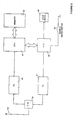
- FIG. 4 of the drawings there is shown the block schematic diagram of the 'PAGEKEY' 33 of Figure 3.
- a paging signal is received by antenna 20 and is fed, via transmit/receive (T/R) switch 46, to a receiver 41 in which it is detected and demodulated.
- the demodulated signal from receiver 41 is decoded by the central processor unit (CPU) 42 and compares the code of the paging signal with the code which was programmed into 'PAGEKEY' 33 and which is stored in memory 43.
- CPU central processor unit
- the message code Z is decoded by the CPU 42 and, via input/output (I/O) driver 44, is used to selectively activate beeper 22, light sources 24 or display 37, the push button 26 being provided for 'reset' purposes.
- I/O input/output
- the 'PAGEKEY' 33 of Figure 4 is provided with a transponder for accessing its stored code and which obviates the need to actually insert the 'PAGEKEY' 33 in a programmable lock mechanism 13 ( Figure 1) when entrance to a hotel room is required.
- the 'PAGEKEY' 33 of Figure 4 When the 'PAGEKEY' 33 of Figure 4 is used in its transponding mode, it receives and decodes an interrogation signal generated by the programmable lock mechanism 13 (as will be described). The combination code which has been programmed into the 'PAGEKEY' 33 and which is stored in memory 43 is then output to the antenna 20 by a short range transmitter 45 via I/O driver 44 and T/R switch 46. The combination code transmitted by the transmitter 45 is received by the programmable lock mechanism which initiated the interrogation signal and is used to selectively open the lock as will be described with reference to Figure 5.
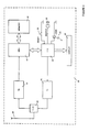
- FIG. 5 of the drawings there is shown a diagrammatic view of a programmable door lock mechanism 13 which is attached to the door or door frame 61 of a hotel room.
- FIG 6 of the drawings there is depicted a block schematic diagram of the programmable door lock mechanism of Figure 5.
- the mechanism 13 comprises a handle 62, the spindle of which is provided with a cam 58 which, when the handle 62 is turned, causes a microswitch 55 or other suitable switch to be operated.
- the output from the microswitch 55 is applied to an access control module 59 which will be described in greater detail with reference to Figure 6.
- the access control module 59 is powered from a battery 51 and is connected to an antenna 52 and to the solenoid 49 of a lock mechanism 50.
- the lock mechanism 50 is provided with a protruding door catch 60 which normally locks the hotel door closed but which is retracted when the solenoid 49 of the lock mechanism 50 is activated to release the door.
- the access control module 59 of Figure 5 comprises a transmit/receive (T/R) switch 54 to which the antenna 52 is connected, a receiver (Rx) 48, a central processor unit (CPU) 47, a memory 53, a short range transmitter (Tx) 57 and input/output (I/O) driver 56 to which the lock mechanism 50 and the microswitch 55 are connected.
- T/R transmit/receive
- CPU central processor unit
- Tx short range transmitter
- I/O input/output
- the programmable door lock mechanism 13 of Figures 5 and 6 operates as follows. Remote programming of the door lock mechanism is achieved by transmitting the required code from the paging base station 15 of Figure 1. This code is received by the antenna 52 and applied via T/R switch 54 to receiver 48 in which it is received and demodulated. The transmitted code is decoded by CPU 47 and stored in memory 53.
- the interrogation signal when the interrogation signal is received by the 'PAGEKEY' 33 it transponds by transmitting its own combination code and this is received by the receiver 48 of Figure 6 via the antenna 52 and T/R switch 54.
- the received combination code is decoded by CPU 47 and if it corresponds to its own code stored in memory 53 it causes the solenoid 49 of the lock mechanism 50 to be activated to cause the door catch 60 (figure 5) to be retracted to release the door and allow access to the hotel room. If the received combination code does not correspond to the code stored in memory 53, this may be indicative of someone trying to make a forced or illegal entry and an alarm signal may be transmitted from the transmitter 57 to the paging base station 15 ( Figure 1) to inform the hotel staff.
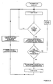
- the flow chart of Figure 8 illustrates the procedure for programming the "PAGEKEY' 23 of Figure 2, the 'PAGEKEY' 33 of Figure 3 and the programmable door lock mechanism of Figures 5 and 6.
- the flow chart of Figure 9 illustrates the operation of the programmable door lock mechanism of Figures 5 and 6.
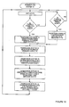
- the flow chart of Figure 10 illustrates the operation of the paging base station 15 of Figure 1.
- the integrated architecture of the 'PAGEKEY' allows it to be readily used as what might be called an electronic purse, charge or credit card. In operation purchases made within the hotel environs may be recorded within the 'PAGEKEY' and debited from a pre-stored credit level or added to a running total of transaction charges.
Abstract
Description
- This invention relates to access control devices sand to systems incorporating such devices. It is particularly applicable to such devices and systems for use within hotel environments, commercial and financial offices and industrial complexes.
- Security is an increasing problem in every walk of life and is particularly acute within the hotel industry. Theft can be in the form of property stolen from hotel bedrooms or it can be in the form of unauthorised and unpaid usage of hotel facilities such as gymnasiums, saunas, swimming pools. Theft can even take the form of unauthorised consumption of food and drink by non-registered guests. Increased security in the form of access control can therefore readily provide benefits for both guest and hotel operator alike. The guests gain from added security, whilst the operator gains from reduced levels of fraud.
- In order to contain the above problems, increasing effort is being focused on the design of secure access control systems.
- Electro-mechanical programmable door locks represent important elements of access control systems and are being installed in increasing numbers, particularly in high technology hotels which cater for the international business traveller. Whenever a new guest registers in one of these hotels he may be allocated a unique 'key' which is coded and can only be used to operate the lock controlling access to his room - and then only during the period of his stay. The 'key' may be constructed from a thin strip of card or plastic or from a laminated hybrid structure.
- Lock code changes are routinely carried out by a member of the hotel staff physically reprogramming the lock mechanisms - usually during or after room preparation. This process is often achieved by the insertion of a two part coded card into the door lock mechanism - one part of the card, containing the new code, being snapped off and left within the lock mechanism, whilst the other part, the 'key', is removed and deposited with hotel check-in staff. The 'key' is then issued to the guest who is allocated the room with the matching coded lock.
- If the 'key' is lost during the guest's stay then the door lock is reprogrammed with another two part coded card and the 'key' portion is once more issued to the guest. When the guest checks out of the hotel the door lock allowing access to the room in which the guest stayed is once again reprogrammed. The old 'key' is either discarded or retained by the guest as a souvenir.
- Lock codes are normally written on a magnetic strip printed or attached by some means onto the surface of the 'key', although it will be appreciated that the same code may be electronically or optically stored within the body of the 'key' or even stored in the form of physical holes or deformations on part of the 'key'.
- Many hotel guests entertain business clients or attend conferences and presentations within hotels whilst simultaneously needing to be kept informed of other business activities via incoming telephone calls and messages. Telephone messages are frequently left with hotel telephone operators when the intended recipient cannot be found; an illuminated light on the guest's telephone being the only indication of a lost telephone call or of a message left with the hotel telephone operator. Such failures to establish direct telephone contact during business negotiations can prove very costly, particularly in situations where accurate information and precise timing are crucial.
- It is an object of the present invention to provide an improved access control device and access control system which incorporates means for communicating with hotel guests whilst they are in the vicinity of the hotel. It will be appreciated that whilst the invention is particularly applicable to the hotel industry, it will have much wider application.
- According to one aspect of the present invention there is provided an access control device which is programmable to allow access to a restricted access area, characterised by pager means which is formed as part of said device for receiving a transmitted paging signal.
- Thus, by incorporating a pager within the usual access control device or electronic 'key', in a hotel application, for example, all guests who have been issued with an electronic key may be paged should contact need to be made with them.
- In a preferred arrangement, said device will take the form of an electronic 'smart' card, which conveniently comprises means for affording an audible or visual indication when a paging signal has been received.
- Advantageously, a received paging signal may be represented by illuminating a light adjacent or near to text which is descriptive of the intended message of the received paging signal, or an alpha-numeric display may be provided for displaying a received paging signal.
- It may be arranged that the access control device is programmed with an electronic, magnetic, optical, mechanical or electrical code to allow access to a restricted access area.
- In an especially preferred arrangement according to the first aspect of the present invention, the access control device will include a transponding arrangement for receiving an interrogation signal and for transponding a predetermined code when an interrogation signal has been received to allow access to a restricted access area.
- Advantageously said access control device may be programmed with a paging code which determines the paging signals which are receivable by said device, and said device may be adapted to be used as an electronic data transfer device e.g. for electronic credit, charge card or data bank purposes.
- According to a second aspect of the present invention there is provided an access control system comprising a plurality of access control devices according to the aforesaid first aspect of the present invention and further comprising coding means for programming each of said access control devices with an access code to allow access to a specified restricted access area, further coding means for programming each specified restricted access area with an access code which corresponds to the access code of one or more of said access control devices, and means for transmitting a coded paging signal to one or more of said access control devices.
- In a preferred arrangement for carrying out the invention according to the second aspect, a programmable security device will be provided for restricting access to each specified restricted access area, said further coding means being effective for programming each programmable security device with an access code, each of said programmable security devices being responsive to one or more access control devices having the same code for allowing access to the specified restricted area thereof.
- In an especially preferred arrangement according to the second aspect of the invention in which said access control devices each include a transponding arrangement, it will be arranged that each programmable security device comprises means for transmitting an interrogating signal when it is actuated, and means for receiving a transponded signal from an access control device which is in receipt of said interrogating signal, said programmable security device being responsive to a transponded signal from an access control device having the same access with which it is programmed for allowing access to the restricted access area thereof.
- It may be arranged that said programmable security devices are programmed manually or are programmed remotely, in which case a signal may be transmitted to said programmable security devices for programming each said programmable security device with its access code.
- In an access control system for use in a hotel reservation system, it may be arranged that said access control devices constitute room key devices which are programmed with an access code which is also programmed into an electronic door lock associated with a specified room of said hotel to allow access to said room when the access code of said access control device corresponds to the access code of said electronic door lock, means being provided for transmitting a coded paging signal to one or more of said access control devices.
- An exemplary embodiment of the invention will now be described reference being made to the accompanying drawings, in which:
- Figure 1 is a block schematic diagram of an access control system in accordance with the present invention;
- Figure 2 is a perspective view of one form of access control device in accordance with the present invention, for use in the system of Figure 1;
- Figure 3 is a perspective view of another form of access control device in accordance with the present invention, for use in the system of Figure 1;
- Figure 4 is a block schematic diagram of the access control device of Figure 3;
- Figure 5 is a diagrammatic perspective view of a programmable door lock mechanism for use in the system of Figure 1;
- Figure 6 is a block schematic diagram of the programmable door lock mechanism of Figure 5;
- Figure 7 is an illustration of typical code fields which can be used to create the combination codes for use in the system of Figure 1 and the access control devices of Figures 2 and 3;
- Figure 8 is a flow chart illustrating the procedure for programming the access control devices of Figures 2 and 3 and the programmable door lock mechanism of Figures 5 and 6;
- Figure 9 is a flow chart illustrating the operation of the programmable door lock mechanism of Figures 5 and 6;
- Figure 10 is a flow chart illustrating the operation of the paging base station of the access control system of Figure 1; and
- Figure 11 is a flow chart illustrating the operation of the access control device of Figures 3 and 4.
- The exemplary embodiment of the invention to be described is based on use in a hotel installation but it should be appreciated that the invention has much wider application and may be used, for example, within commercial, industrial, business, sports and leisure environments.
- The invention is based on the use of an access control device in the form of an electronic 'key' which incorporates a 'pager' which may be used to make contact with the person who has possession of the 'key'. For the purposes of the following description the electronic 'key' incorporating the pager will be referred to as a 'PAGEKEY'.
- The access control system which is to be described is based on the use of a programmable door lock mechanism which is fitted to each of the hotel rooms, each of the door lock mechanisms being programmed with a unique code such that it can only be opened, to gain access to the room, by a 'PAGEKEY' which is coded with the same unique code. Each 'PAGEKEY' is provided with a paging facility for receiving a transmitted paging signal which is used to contact the person in possession of the 'PAGEKEY'.
- In Figure 1 of the drawings there is shown a hotel access control system which comprises a
control unit 18, which is typically located on or near the hotel reception desk. Each of the rooms of the hotel is fitted with a programmabledoor lock mechanism 13 and aroom telephone 17, and each guest of the hotel is provided with a 'PAGEKEY' 14. - The
control unit 18 comprises a reception check-inconsole 11 which is interconnected with thehotel telephone exchange 16, a 'PAGEKEY' andlock programmer 12, and a 'PAGEKEY'paging base station 15. - When a new guest checks into the hotel, the receptionist identifies a suitable room for the guest via the check-in
console 11 which also generates a suitable code which is to be allocated to that particular room for the period that the room is to be allocated to the new guest. The code generated by check-inconsole 11 is fed to the 'PAGEKEY' and lockprogrammer 12 into which is inserted the 'PAGEKEY' 14 which is to be allocated to the new guest. The 'PAGEKEY' andlock programmer 12 codes the 'PAGEKEY' 14 with the required code and the code is also fed to the 'PAGEKEY'paging base station 15 where it is transmitted via aerial 19 to the programmabledoor lock mechanism 13, via its aerial 52, of the room which has been allocated to the new guest. The coded 'PAGEKEY' is then issued to the new guest which enables them to gain access only to the room which has been allocated to them. Other areas of the hotel which are provided only for the benefit of hotel guests, such as gymnasiums, saunas, swimming pools, etc. may also be provided with programmabledoor lock mechanisms 13, which are programmed such that any guest having a valid 'PAGEKEY' can gain access thereto. - If the hotel receptionist needs to contact a particular hotel guest for any reason, a coded paging signal is transmitted by the 'PAGEKEY' paging and
base station 15, via its aerial 19, to the appropriately coded 'PAGEKEY' lin, via its aerial 20. In this way the hotel receptionist can make direct contact with any required hotel guest. It may also be arranged that when a telephone call is received for a hotel guest, when the call is transferred to the guest's room telephone, if the guest is absent and unable to answer the call, it may be arranged that a paging signal is transmitted to the 'PAGEKEY' of the hotel guest in question who will then know that contact should be made to the hotel reception. - The paging signal which is transmitted to the 'PAGEKEY' 14 by the 'PAGEKEY'
paging base station 15 of Figure 1 may take a variety of different forms. - Radio page receivers are finding widespread use throughout the world and are currently classified into two types. Firstly, there is the type which only generates an attention getting tone or flashes a light emitting diode (LED) on reception and identification of an appropriate call code. For the purposes of this invention this receiver will be called a tone-only type of receiver. The second type of receiver can display a variety of messages in addition to the generation of an audible tone and will be called a receiver of the display type.
- There are also different types of paging system which provide varying degrees of coverage. For example, some systems provide paging coverage over typically several hundred miles or more, whilst other systems hereafter referred to as local area paging systems, provide coverage restricted to defined areas such as industrial or commercial premises. Of particular relevance to this invention is the local area paging system which may use electromagnetic radiation, inductive pick-up, ultrasonic or infra-red radiation as a means of data communication between base station and receiver and in some cases between receiver and base station.
- In Figure 2 of the drawings there is shown a 'PAGEKEY' 23 (corresponding to 'PAGEKEY' 14 of Figure 1) which incorporates a tone-only type of page receiver. The 'PAGEKEY' 23 is based on 'smart card' technology and is similar in construction to a thin pocket calculator and consists of an electronic structure incorporating typically semiconductor memories, processing and communication circuits, an antenna, etched or wound coils, tone transducers, displays, switches and subminiature batteries. The 'PAGEKEY' 23 includes a magnetic, optical, mechanical, or electronically readable strip or
electrical connection 21 attached to it, and by means of which the unique code which is allocated to the 'PAGEKEY' 23 is stored therein or input thereto. When the 'PAGEKEY' 23 receives a paging signal it illuminates alight source 24, which may, for example, be indicative of a telephone call having been received as indicated by the 'TELEPHONE'message 25, and/or it may emit an audible tone frombeeper 22. The light 24 and the audible tone may be terminated manually by operating apush button 26 or they may be terminated by the reception console unit 18 (Figure 1). - In Figure 3 of the drawings there is shown a 'PAGEKEY' 33 (corresponding to 'PAGEKEY' 14 of Figure 1), which is similar to the 'PAGEKEY' 23 of Figure 2 but which is of the display type and which, as will be described, incorporates a transponder for accessing its stored code. The 'PAGEKEY' 33 of Figure 3 includes three
light sources 24 each associated with a particulardedicated message 25 printed on the surface of the 'PAGEKEY' 33, thelight sources 24 being selectively lit in response to a received paging signal dependent upon the particular dedicated message being sent. The 'PAGEKEY' 33 is also provided with analphanumeric display 37 by means of which messages stored within the 'PAGEKEY' 33 can be displayed. - In Figure 7 of the drawings, there is shown a typical code field for generating a combination code suitable for use with the access control system of Figure 1 and the 'PAGEKEY' of Figure 3. The code series of Figure 7 comprises a 'Guest' code X (typically of 16 bits) as indicated at 71, a 'Room' code Y (typically of 12 bits) as indicated at 72, and a 'Message' code Z (typically 4 bits) as indicated at 73. It will be appreciated that the combination of codes may be achieved using a variety of techniques, the salient feature being that part of the code is determined from the code allocated to the guest and part from the code allocated to either the room number or phone extension within the room. If the guest code X consisted of 16 binary bits for example, then 65,536 unique guest codes could be issued before all code possibilities were exhausted. If the room code Y consisted of 12 binary bits, then 4,096 unique room codes could be allocated before all room code possibilities were exhausted.
- It is an additional feature of this invention that by combining every possible 16 bit guest code X with every possible 12 bit room code Y, a total of 268,435,456 unique guest/room combination codes could be issued before all combination codes were exhausted. Such a quantity of numbers is considered to be sufficient to provide more than adequate security in any high-technology hotel or environment. The possibility of an intruder successfully hacking a counterfeit 'PAGEKEY' combination code is considered improbable, and in any case the 'hacking' process may readily be detected by the programmable door lock mechanism 13 (Figure 1).
- It will be appreciated that although 16 and 12 bit codes have been used in the above example, larger or smaller codes may be used depending on the number of unique combination codes required.
- The
message code 73 may be used to transmit the particular message which 'PAGEKEY' 33 of Figure 3 is required to display. With a 4 bit code up to sixteen different messages may be selected, but it should be appreciated that themessage code 73 may comprise more or less bits dependent upon the number of displayed messages required. - In Figure 4 of the drawings there is shown the block schematic diagram of the 'PAGEKEY' 33 of Figure 3. When the 'PAGEKEY' 33 of Figure in is used in the paging mode, a paging signal is received by
antenna 20 and is fed, via transmit/receive (T/R)switch 46, to areceiver 41 in which it is detected and demodulated. The demodulated signal fromreceiver 41 is decoded by the central processor unit (CPU) 42 and compares the code of the paging signal with the code which was programmed into 'PAGEKEY' 33 and which is stored in memory 43. If the two codes correspond then the message code Z is decoded by theCPU 42 and, via input/output (I/O)driver 44, is used to selectively activatebeeper 22,light sources 24 ordisplay 37, thepush button 26 being provided for 'reset' purposes. - As has already been mentioned, the 'PAGEKEY' 33 of Figure 4 is provided with a transponder for accessing its stored code and which obviates the need to actually insert the 'PAGEKEY' 33 in a programmable lock mechanism 13 (Figure 1) when entrance to a hotel room is required.
- When the 'PAGEKEY' 33 of Figure 4 is used in its transponding mode, it receives and decodes an interrogation signal generated by the programmable lock mechanism 13 (as will be described). The combination code which has been programmed into the 'PAGEKEY' 33 and which is stored in memory 43 is then output to the
antenna 20 by ashort range transmitter 45 via I/O driver 44 and T/R switch 46. The combination code transmitted by thetransmitter 45 is received by the programmable lock mechanism which initiated the interrogation signal and is used to selectively open the lock as will be described with reference to Figure 5. - In Figure 5 of the drawings there is shown a diagrammatic view of a programmable
door lock mechanism 13 which is attached to the door ordoor frame 61 of a hotel room. In Figure 6 of the drawings there is depicted a block schematic diagram of the programmable door lock mechanism of Figure 5. Themechanism 13 comprises ahandle 62, the spindle of which is provided with acam 58 which, when thehandle 62 is turned, causes amicroswitch 55 or other suitable switch to be operated. The output from themicroswitch 55 is applied to anaccess control module 59 which will be described in greater detail with reference to Figure 6. Theaccess control module 59 is powered from abattery 51 and is connected to anantenna 52 and to thesolenoid 49 of alock mechanism 50. Thelock mechanism 50 is provided with a protrudingdoor catch 60 which normally locks the hotel door closed but which is retracted when thesolenoid 49 of thelock mechanism 50 is activated to release the door. - Turning now to Figure 6, the
access control module 59 of Figure 5 comprises a transmit/receive (T/R) switch 54 to which theantenna 52 is connected, a receiver (Rx) 48, a central processor unit (CPU) 47, amemory 53, a short range transmitter (Tx) 57 and input/output (I/O)driver 56 to which thelock mechanism 50 and themicroswitch 55 are connected. - The programmable
door lock mechanism 13 of Figures 5 and 6 operates as follows. Remote programming of the door lock mechanism is achieved by transmitting the required code from thepaging base station 15 of Figure 1. This code is received by theantenna 52 and applied via T/R switch 54 toreceiver 48 in which it is received and demodulated. The transmitted code is decoded byCPU 47 and stored inmemory 53. - When a 'PAGEKEY' 33 (Figure 3) is in the vicinity of the programmable
door lock mechanism 13 and thehandle 62 thereof is turned, the closing of themicroswitch 55 is detected by theCPU 47 via I/O driver 56, and is used to generate an interrogation signal which is transmitted bytransmitter 57 andantenna 52 via I/O driver 56 and T/R switch 54. - As has been described with reference to Figure 4, when the interrogation signal is received by the 'PAGEKEY' 33 it transponds by transmitting its own combination code and this is received by the
receiver 48 of Figure 6 via theantenna 52 and T/R switch 54. The received combination code is decoded byCPU 47 and if it corresponds to its own code stored inmemory 53 it causes thesolenoid 49 of thelock mechanism 50 to be activated to cause the door catch 60 (figure 5) to be retracted to release the door and allow access to the hotel room. If the received combination code does not correspond to the code stored inmemory 53, this may be indicative of someone trying to make a forced or illegal entry and an alarm signal may be transmitted from thetransmitter 57 to the paging base station 15 (Figure 1) to inform the hotel staff. - In Figures 8 to 11 of the accompanying drawings, there are shown various flow charts which illustrate the operation of the access control system and 'PAGEKEYS' herein described.
- The flow chart of Figure 8 illustrates the procedure for programming the "PAGEKEY' 23 of Figure 2, the 'PAGEKEY' 33 of Figure 3 and the programmable door lock mechanism of Figures 5 and 6.
- The flow chart of Figure 9 illustrates the operation of the programmable door lock mechanism of Figures 5 and 6.
- The flow chart of Figure 10 illustrates the operation of the
paging base station 15 of Figure 1. - The flow chart of Figure II illustrates the operation of the 'PAGEKEY' 33 of Figures 3 and 4.
- It should be appreciated that the embodiment of the invention which has been described has been given by way of example only and various modifications may be made whilst still utilising the basic principles thereof. For example, instead of using transmitted signals for programming the programmable door lock mechanisms they may be individually manually programmed as has been described, they may be programmed using fixed wiring between the mechanisms and a programming console, or they may be programmed through the electrical mains wiring using, for example, frequency shift keying (FSK) techniques. Also, although it is advantageous to use a transponding type 'PAGEKEY', a non-transponding type may equally well be used.
- It will also be appreciated that the integrated architecture of the 'PAGEKEY' allows it to be readily used as what might be called an electronic purse, charge or credit card. In operation purchases made within the hotel environs may be recorded within the 'PAGEKEY' and debited from a pre-stored credit level or added to a running total of transaction charges.
Claims (17)
Applications Claiming Priority (4)
| Application Number | Priority Date | Filing Date | Title |
|---|---|---|---|
| GB898920104A GB8920104D0 (en) | 1989-09-06 | 1989-09-06 | Access control devices and systems incorporating such devices |
| GB8920104 | 1989-09-06 | ||
| GB9018501A GB2236354B (en) | 1989-09-06 | 1990-08-23 | Access control devices and systems incorporating such devices |
| GB9018501 | 1990-08-23 |
Publications (2)
| Publication Number | Publication Date |
|---|---|
| EP0416792A2 true EP0416792A2 (en) | 1991-03-13 |
| EP0416792A3 EP0416792A3 (en) | 1993-03-03 |
Family
ID=26295876
Family Applications (1)
| Application Number | Title | Priority Date | Filing Date |
|---|---|---|---|
| EP19900309364 Withdrawn EP0416792A3 (en) | 1989-09-06 | 1990-08-28 | Access control devices and systems incorporating such devices |
Country Status (2)
| Country | Link |
|---|---|
| EP (1) | EP0416792A3 (en) |
| GB (1) | GB2236354B (en) |
Cited By (12)
| Publication number | Priority date | Publication date | Assignee | Title |
|---|---|---|---|---|
| WO1993018476A1 (en) * | 1992-03-11 | 1993-09-16 | Olivetti Research Limited | Tracking and/or identification system |
| WO1998024071A1 (en) * | 1996-11-25 | 1998-06-04 | Security Signs & Service As | Security and alarm device for keys/key cards |
| EP0874945A1 (en) * | 1995-12-20 | 1998-11-04 | Electronic Locking Systems Limited | Remote control of electronic locking systems |
| EP0969434A1 (en) * | 1998-06-30 | 2000-01-05 | Lucent Technologies Inc. | Wireless terminal automatically alerting user upon wireless terminal entering a specified physical location |
| EP0704590A3 (en) * | 1994-09-30 | 2000-05-24 | Sony Corporation | Remote operating system |
| FR2786875A1 (en) * | 1998-12-07 | 2000-06-09 | Alain Vaucelle | Search and locate system for person in defined location uses set of beacons transmitting signals and measuring response from responder carried by person |
| GB2364202A (en) * | 2000-06-27 | 2002-01-16 | Nokia Mobile Phones Ltd | Mobile phone for opening locks |
| WO2003046824A2 (en) * | 2001-11-21 | 2003-06-05 | Marconi Intellectual Property (Us) Inc. | Wireless communication device interconnectivity |
| FR2839833A1 (en) * | 2002-05-15 | 2003-11-21 | Cogelec | Access control system using transponder keys includes separate programming terminal used to modify operating parameters of control |
| EP2355050A3 (en) * | 2010-01-29 | 2012-09-05 | Assa Abloy Hospitality, Inc. | Method and system for permitting remote check-in and coordinating access control |
| US8914863B2 (en) | 2013-03-29 | 2014-12-16 | Here Global B.V. | Enhancing the security of near-field communication |
| US9485607B2 (en) | 2013-05-14 | 2016-11-01 | Nokia Technologies Oy | Enhancing the security of short-range communication in connection with an access control device |
Families Citing this family (2)
| Publication number | Priority date | Publication date | Assignee | Title |
|---|---|---|---|---|
| GB9018531D0 (en) * | 1990-08-23 | 1990-10-10 | Taylor Michael R | Programmable security locks |
| DE19513498C1 (en) * | 1995-04-10 | 1996-06-27 | Daimler Benz Ag | Electronic car key |
Citations (7)
| Publication number | Priority date | Publication date | Assignee | Title |
|---|---|---|---|---|
| FR2291553A1 (en) * | 1974-11-12 | 1976-06-11 | Genelec | Paging system for hotels - makes use of hotel keys each incorporating miniature radio receiver with clip for securing on person |
| JPS5981932A (en) * | 1982-11-02 | 1984-05-11 | Matsushita Electric Ind Co Ltd | Selective calling device |
| EP0218251A1 (en) * | 1985-10-11 | 1987-04-15 | Bayerische Motoren Werke Aktiengesellschaft, Patentabteilung AJ-3 | Safety device for motor vehicles |
| EP0320373A1 (en) * | 1987-12-08 | 1989-06-14 | Jacques Lewiner | Operating and controlling systems for a plurality of accesses equipped with coded locks |
| US4864115A (en) * | 1986-08-22 | 1989-09-05 | Datatrak, Inc. | Electronic access card having key pads and coils and combination using the same |
| WO1990013989A1 (en) * | 1989-04-28 | 1990-11-15 | Motorola, Inc. | Printed circuit board having multiple form factors |
| EP0475616A1 (en) * | 1990-08-23 | 1992-03-18 | Incomefirst Limited | Programmable security locks |
-
1990
- 1990-08-23 GB GB9018501A patent/GB2236354B/en not_active Expired - Fee Related
- 1990-08-28 EP EP19900309364 patent/EP0416792A3/en not_active Withdrawn
Patent Citations (7)
| Publication number | Priority date | Publication date | Assignee | Title |
|---|---|---|---|---|
| FR2291553A1 (en) * | 1974-11-12 | 1976-06-11 | Genelec | Paging system for hotels - makes use of hotel keys each incorporating miniature radio receiver with clip for securing on person |
| JPS5981932A (en) * | 1982-11-02 | 1984-05-11 | Matsushita Electric Ind Co Ltd | Selective calling device |
| EP0218251A1 (en) * | 1985-10-11 | 1987-04-15 | Bayerische Motoren Werke Aktiengesellschaft, Patentabteilung AJ-3 | Safety device for motor vehicles |
| US4864115A (en) * | 1986-08-22 | 1989-09-05 | Datatrak, Inc. | Electronic access card having key pads and coils and combination using the same |
| EP0320373A1 (en) * | 1987-12-08 | 1989-06-14 | Jacques Lewiner | Operating and controlling systems for a plurality of accesses equipped with coded locks |
| WO1990013989A1 (en) * | 1989-04-28 | 1990-11-15 | Motorola, Inc. | Printed circuit board having multiple form factors |
| EP0475616A1 (en) * | 1990-08-23 | 1992-03-18 | Incomefirst Limited | Programmable security locks |
Non-Patent Citations (2)
| Title |
|---|
| MOTOROLA TECHNICAL DEVELOPMENTS vol. 10, March 1990, SCHAUMBURG, ILLINOIS, US page 36 G. MARINO 'Pager and Garage Door Opener Combination' * |
| PATENT ABSTRACTS OF JAPAN vol. 8, no. 194 (E-264)(1631) 6 September 1984 & JP-A-59 081 932 ( MATSUSHITA DENKI SANGYO ) 11 May 1984 * |
Cited By (21)
| Publication number | Priority date | Publication date | Assignee | Title |
|---|---|---|---|---|
| WO1993018476A1 (en) * | 1992-03-11 | 1993-09-16 | Olivetti Research Limited | Tracking and/or identification system |
| EP0704590A3 (en) * | 1994-09-30 | 2000-05-24 | Sony Corporation | Remote operating system |
| EP0874945A1 (en) * | 1995-12-20 | 1998-11-04 | Electronic Locking Systems Limited | Remote control of electronic locking systems |
| EP0874945A4 (en) * | 1995-12-20 | 1999-04-28 | Electronic Locking Systems Lim | Remote control of electronic locking systems |
| WO1998024071A1 (en) * | 1996-11-25 | 1998-06-04 | Security Signs & Service As | Security and alarm device for keys/key cards |
| EP0969434A1 (en) * | 1998-06-30 | 2000-01-05 | Lucent Technologies Inc. | Wireless terminal automatically alerting user upon wireless terminal entering a specified physical location |
| US6236858B1 (en) | 1998-06-30 | 2001-05-22 | Avaya Technology Corp. | Wireless terminal automatically alerting user upon wireless terminal entering a specified physical location |
| FR2786875A1 (en) * | 1998-12-07 | 2000-06-09 | Alain Vaucelle | Search and locate system for person in defined location uses set of beacons transmitting signals and measuring response from responder carried by person |
| US7873989B2 (en) | 2000-06-27 | 2011-01-18 | Nokia Corporation | Wireless access device |
| GB2364202A (en) * | 2000-06-27 | 2002-01-16 | Nokia Mobile Phones Ltd | Mobile phone for opening locks |
| WO2003046824A2 (en) * | 2001-11-21 | 2003-06-05 | Marconi Intellectual Property (Us) Inc. | Wireless communication device interconnectivity |
| WO2003046824A3 (en) * | 2001-11-21 | 2003-08-28 | Marconi Comm Inc | Wireless communication device interconnectivity |
| US7366466B2 (en) | 2001-11-21 | 2008-04-29 | Mineral Lassen Llc | Wireless communication device interconnectivity |
| US7536155B2 (en) | 2001-11-21 | 2009-05-19 | Ian J Forster | Wireless communication device interconnectivity |
| US7623831B2 (en) | 2001-11-21 | 2009-11-24 | Ian J Forster | Wireless communication device interconnectivity |
| FR2839833A1 (en) * | 2002-05-15 | 2003-11-21 | Cogelec | Access control system using transponder keys includes separate programming terminal used to modify operating parameters of control |
| EP2355050A3 (en) * | 2010-01-29 | 2012-09-05 | Assa Abloy Hospitality, Inc. | Method and system for permitting remote check-in and coordinating access control |
| US8730004B2 (en) | 2010-01-29 | 2014-05-20 | Assa Abloy Hospitality, Inc. | Method and system for permitting remote check-in and coordinating access control |
| US9818244B2 (en) | 2010-01-29 | 2017-11-14 | Assa Abloy Ab | Method and system for permitting remote check-in and coordinating access control |
| US8914863B2 (en) | 2013-03-29 | 2014-12-16 | Here Global B.V. | Enhancing the security of near-field communication |
| US9485607B2 (en) | 2013-05-14 | 2016-11-01 | Nokia Technologies Oy | Enhancing the security of short-range communication in connection with an access control device |
Also Published As
| Publication number | Publication date |
|---|---|
| EP0416792A3 (en) | 1993-03-03 |
| GB2236354B (en) | 1993-07-21 |
| GB9018501D0 (en) | 1990-10-10 |
| GB2236354A (en) | 1991-04-03 |
Similar Documents
| Publication | Publication Date | Title |
|---|---|---|
| US7536721B2 (en) | Low cost secure ID card and system | |
| US4609780A (en) | Electronic secure entry system, apparatus and method | |
| EP0416792A2 (en) | Access control devices and systems incorporating such devices | |
| US5979754A (en) | Door lock control apparatus using paging communication | |
| US4808993A (en) | Electronic secure entry system, apparatus and method | |
| US5614703A (en) | Hotel check-in system with wireless communication | |
| US6340116B1 (en) | Proximity card with incorporated pin code protection | |
| US20020106202A1 (en) | Portable cameras | |
| EP1028396A2 (en) | Automatic identification equipment and IC cards | |
| US20040036573A1 (en) | Method and apparatus for providing access to a secure region | |
| WO1991008619A1 (en) | On-site communication system having pager identification capability | |
| EP0475616B1 (en) | Programmable security locks | |
| WO1990013096A1 (en) | Credit card with communication capability | |
| WO1987002491A1 (en) | Personal identification device | |
| PT1237445E (en) | Secure delivery or collection system | |
| KR100533148B1 (en) | Portable object, in particular a watch, including multiple selectable electronic modules | |
| WO2005080715A1 (en) | Enhanced automated key selection system | |
| GB2102996A (en) | Security system | |
| US6742714B2 (en) | Proximity card with incorporated PIN code protection | |
| GB2180677A (en) | Card and card system | |
| JPH0567258A (en) | Id card corresponding type security device | |
| JP3579107B2 (en) | Door key device | |
| GB2362188A (en) | Security system for lockable enclosures | |
| CN218866527U (en) | Intelligent cabinet lock system and storage cabinet | |
| AU2002100103A4 (en) | Object and document management system |
Legal Events
| Date | Code | Title | Description |
|---|---|---|---|
| PUAI | Public reference made under article 153(3) epc to a published international application that has entered the european phase |
Free format text: ORIGINAL CODE: 0009012 |
|
| AK | Designated contracting states |
Kind code of ref document: A2 Designated state(s): AT BE CH DE DK ES FR GB GR IT LI LU NL SE |
|
| PUAL | Search report despatched |
Free format text: ORIGINAL CODE: 0009013 |
|
| AK | Designated contracting states |
Kind code of ref document: A3 Designated state(s): AT BE CH DE DK ES FR GB GR IT LI LU NL SE |
|
| 17P | Request for examination filed |
Effective date: 19930729 |
|
| 17Q | First examination report despatched |
Effective date: 19950331 |
|
| RIN1 | Information on inventor provided before grant (corrected) |
Inventor name: TAYLOR, MICHAEL ROBINSON Inventor name: GAUTIER, MICHAEL JOSEPH |
|
| RAP1 | Party data changed (applicant data changed or rights of an application transferred) |
Owner name: INCOMEFIRST LIMITED |
|
| STAA | Information on the status of an ep patent application or granted ep patent |
Free format text: STATUS: THE APPLICATION IS DEEMED TO BE WITHDRAWN |
|
| 18D | Application deemed to be withdrawn |
Effective date: 19980303 |