EP0414950A1 - Method of switching voice and/or data information distributively transmitted in several time slots - Google Patents
Method of switching voice and/or data information distributively transmitted in several time slots Download PDFInfo
- Publication number
- EP0414950A1 EP0414950A1 EP89116144A EP89116144A EP0414950A1 EP 0414950 A1 EP0414950 A1 EP 0414950A1 EP 89116144 A EP89116144 A EP 89116144A EP 89116144 A EP89116144 A EP 89116144A EP 0414950 A1 EP0414950 A1 EP 0414950A1
- Authority
- EP
- European Patent Office
- Prior art keywords
- time
- memory
- division multiplex
- information
- feeder
- Prior art date
- Legal status (The legal status is an assumption and is not a legal conclusion. Google has not performed a legal analysis and makes no representation as to the accuracy of the status listed.)
- Granted
Links
Images


Classifications
-
- H—ELECTRICITY
- H04—ELECTRIC COMMUNICATION TECHNIQUE
- H04Q—SELECTING
- H04Q11/00—Selecting arrangements for multiplex systems
- H04Q11/04—Selecting arrangements for multiplex systems for time-division multiplexing
- H04Q11/08—Time only switching
Definitions
- the invention relates to a method for switching voice and / or data information transmitted to a plurality of time slots of time channels of a digital time-division multiplex system distributed to feeder and customer time-division multiplex lines with the aid of a time coupling stage to which the time division multiplex lines are connected and in the time step memory of which on the Feeder time-division multiplex lines are cyclically written in or their time-step memory is used to selectively read this information onto the customer time-division multiplex lines in accordance with the read addresses provided during the cyclical reading out of a latch.
- the distribution of the voice and / or data to be transmitted over several time channels (multi-channel connections) is particularly suitable in ISDN-enabled digital telephone networks, in which telecommunications services are offered that require a higher bit transmission rate than the conventional telephone service, e.g. B. telephony or the transmission of fax signals.
- the conference facility of a switching center is used to carry out the multi-channel connections, but this is also only possible if the feeder and customer lines have the same time stamps.
- the object of the invention is to provide a method for carrying out multi-channel connections that meets the requirements for timely switching of the individual channel information under the above-mentioned condition of the coupling stage implementation in the form of a time coupling stage, without the time stamp allocation of the multiplex lines increasing and decreasing and restrictions regarding the number of related time channels have to be added.
- the method according to the invention includes multi-channel connections in which there are no restrictions either with regard to the interface conditions within the system and thus with the time stamps of the feeder and customer time-division multiplex lines, nor with regard to the relationship between the time channels allocated for a multi-channel connection, nor with regard to the number of sub-channels low hardware requirements can be achieved.
- the throughput times through the time step memory are as short as possible.
- An essential component of the time coupling stage according to FIG. 1 is a time stage memory SM, to which the feeder time-division multiplex line Zu1 to Zun and the output side consumer time-division multiplex line A1 to An are connected, provided that the same transmission speed prevails on the feeder and customer time division multiplex lines.
- the voice and data information delivered on the feeder lines in serial form in time slots of time channels undergoes a conversion into parallel form before being registered; in a corresponding manner, the data read out in parallel from the time step memory are converted into series form before they are passed on, in time slots formed on the customer lines.
- the time step memory SM has such a storage capacity that it is capable of receiving the maximum amount of information delivered within a pulse frame on the connected feeder lines.
- the writing into the time step memory SM from the feeder lines takes place cyclically, whereas the reading on the customer lines is carried out optionally.
- the control addresses for such an optional readout are in a hold memory CM included, which is also controlled cyclically when reading out.
- a feeder line Zu which is supposed to be a time-division multiplex line with a transmission rate of 2.048 Mbit / s, on which 32 time channels are formed, and on a customer line An, which has a bit rate of 8.192 Mbit / s should be operated, and on which time slots for 128 time channels are formed.
- FIG. 2 shows that these two time-division multiplex lines have different time marks ZM1 and ZM2, that the pulse frame beginnings do not coincide in time when information is transmitted to these time-division multiplex lines.
- a multi-channel connection in which time channels 0 to 3 are included, it becomes one in the time conversion by a time coupling stage according to FIG. 1 in connection with the information written into the time stage memory SM on time slot 3 on the feeder line Pulse frame jump come because the reading takes place during the time slot 3 formed on the customer line An before the writing of the information that is delivered during the time slot 3 on the feeder line is completed.
- time slot 3 information is read out from the time step memory that comes from the previous pulse frame, whereas the information read out during time slots 0 to 2 formed on the customer line come from the most recent pulse frame.
- FIG. 3 again shows timing constellations on a feeder line Zu and a subscriber line An, but these are multiplex lines with the same transmission speed.
- the time slots of the feeder channels u, v, w, and z are so unfavorable compared to the time slots of the customer channels a, b, c and d that during the time slots of the customer channels a, b and c
- Information of the time channels u, v and w are read out, which still originate from the old pulse frame, whereas, during the time position of the time channel d, information originating from the time channel z is read out, which originates from the current pulse frame, so that a pulse frame jump occurs again here.
- the time step memory SM of the time coupling step according to FIG. 4 which is suitable for carrying out the method according to the invention, has a double storage capacity, so that it can receive information that is delivered in the course of two pulse frames on the feeder lines Zu1 to Zun.
- a total of 512 time channels per pulse frame are formed on the feeder lines, which can be multiplex lines of different transmission capacities, so that the time step memory has two memory halves, each with 512 memory cells for a speech signal or data word.
- the voice and data information delivered on the feeder time-division multiplex lines Zu1 to Zn is cyclically after a series-parallel conversion, one after the other in the two memory halves, for which purpose a write counter Z-WR supplies 1024 write-in addresses in succession.
- the latch CM of the time coupling stage according to FIG 4, which provides the control addresses for the optional reading of the information from the voice memory, which then arrive after parallel-serial conversion on the customer lines A1 to An, contains 512 partial addresses, each of which 512 memory locations in the Correspond to time step memories and which are supplemented by a most significant bit, the so-called frame control bit, which decides whether the reading is carried out from the first or from the second half of the time step memory.
- the read control of the hold memory CM is carried out by a read counter Z-RD, which cyclically supplies 512 read addresses for the hold memory in succession.
- the entries in the hold memory CM and in particular the setting of the frame control bit are carried out by a processor P, which in turn is under the control of a central controller (not shown here), the memory of which contains the data relating to the time-division multiplex lines or time channels to be connected.
- the decision as to which half of the time step memory the reading is made from and thus the determination of the binary value of the frame control bit is made in such a way that successively read related information distributed over the time slots of several time channels comes from the same, and if possible from the most recent pulse frame.
- the processor determines the spatial position of the memory area in the time step memory assigned to the relevant feeder time division multiplex line in accordance with its time mark, the phase relation between the cyclically occurring write-in addresses of the time step memory, which the counter Z-WR supplies, and the cyclically occurring read control addresses of the hold memory CM the counter Z-RD delivers, evaluated in each case during the time slots of the relevant customer channels on the relevant customer time-division multiplex line.
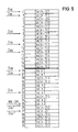
- FIG. 5 an allocation of the time stage memory halves is first illustrated in FIG. 5 in general form, assuming different time marks for the connected feeder time-division multiplex lines.
- the connection of four feeder lines Zuq, Zux, Zuy and Zuz as well as corresponding customer lines is assumed and, for simplification, provided that four time channels are formed on each of these feeder and customer lines.
- Corresponding arrows indicate the time stamps of the feeder time-division multiplex lines, which indicate the times of the pulse frame starts on these time-division multiplex lines or the memory specify or designate the memory areas which are assigned to the time-division multiplex lines in the time-step memory.
- information that is delivered on the feeder train is stored in a memory area of the first half of the time step memory, which extends from its memory cell 0 to its memory cell 12, or in the second half of the time step memory in a memory area, which is provided by the memory cell 16 extends to memory cell 28. From the entries in the memory cells 0, 4, 8 and 12 or 16, 20, 24 it can be seen that in the memory cells of the assigned area in the first half of the memory information of a pulse frame n-1 and in the memory cells of the memory area in the second half of the memory information of the following pulse frame n are entered.
- the memory areas assigned to the individual feeder lines partially overlap and partly belong to both the first and the second half of the memory.
- the feeder line Zuy is thus assigned memory areas which range from the memory cell 6 in the first half of the storage time stage to cell 18 in the second half of the time storage stage or from the memory cell 22 in the second half of the storage stage to memory cell 2 in the first half of the time storage stage.
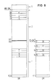
- FIGS. 6 to 10 illustrate different time constellations of a multi-channel connection in which the time coupling stage converts time channels from time channels A to D on one Feeder / customer time division multiplex line pair, which should be 2.048 MHz lines, are carried out on time channels e to h on another pair of feeder / customer line, which should be 8.096 MHz lines. It is assumed that the time-division multiplex lines of the feeder / customer lines of a pair have the same time marks.
- FIG 6 shows, the relationships with regard to the information transfer from time channels A to D on the feeder line of one line pair to time channels e to h on the customer line of the other pair are illustrated.
- the memory cells 0.5, 10 and 15 in the one half of the column and 512, 517, 522, 527 in the second half of the memory are occupied with the information from the subchannels A to D.
- the figure also shows the current position of the write pointer of the time step memory WRSM in the memory cell 3 in the first half of the time step memory SM, wherein information is written that comes from the most recent pulse frame n.
- information originating from the pulse frame n-2 is overwritten.
- the second half of the memory contains information that comes from the pulse frame n-1.
- the addresses of the memory cells 0, 5, 10 and 15 of the time step memory SM are entered in the latch CM according to FIG. 6 in connection with the switching mentioned in lines 30 to 33, which correspond to the relevant time channels on the 8.096 MHz multiplex line.
- the read pointer RD-ZM indicates that the memory cell 30 of the hold memory is being read at the time in question.
- the write pointer WR-SM of the time-step memory overflows the latter memory cells, so that information from the pulse frame n is already read out from some of the cells and information from the frame n-2 is read out from another part of the same, so that a frame jump occurs .
- the reading out must take place from the second half of the time step memory SM, with which time channel information of channels A to D originating from frame n-1 is read out uniformly.
- the frame control bit in the latch CM has the binary value 1, which, in a manner not shown here, causes the readout from the time-step memory SM to always take place from the half of the memory into which the data is not currently being written.
- the ratios shown in FIG. 7 differ from those in FIG. 6 by a different phase relation of the write pointer WR-SM of the time-step memory SM and the read pointer RD-ZM of the latch CM.
- the write pointer WR-SM of the time step memory has already overflowed all the memory cells 0.5, 10 and 15 and has written with information of the pulse frame n. Since it does not reach the second half of the memory during the overflow of the memory cells 30 to 33 by the latch read pointer RD-ZM, it could be read from both the first and the second half of the memory from the point of avoiding frame jumps.
- the frame control bit is set to the binary value 0, with the result that the same half of the memory is always read out is currently being written into, in this case currently from the first half of the memory.
- the information delivered here in the time channels e to h on the feeder line of the 8.096 MHz time-division multiplex line pair is therefore stored in the memory cells 30 to 33 of the first half of the time memory or 532 to 535 of the second half of the time memory.
- the read pointer WR-SM just points to the memory cell 28.
- the memory cells 0.5, 10 and 15 of the hold memory CM contain the addresses with which the time step memory cells 30 to 33 mentioned are activated during the readout.
- the read pointer of the latch CM has its memory cell 0 here. Also in the phase constellation shown in FIG.
- the memory cells 30 to 33 to be read out are overflowed by the write pointer WR-SM while the read pointer RD CM overflows the memory cells 0 to 15 of the latch, so that here too, in order to avoid frame jumps, reading must take place from the other half of the memory into which the data is being written.
- the frame control bits for the relevant readout addresses must therefore have the binary value 1.
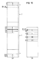
- FIG. 9 corresponds to the memory cells under consideration in the time step memory and in the hold memory of FIG. 8, but deviating from this, a different time position of the write pointer WR-SM is assumed, which at time (1) is in one of the last memory cells of the first half of the time step memory and at time (2) on one of the first memory cells of the second half of the time step memory.
- a frame jump cannot occur.
- the write pointer position (1) according to the assumption in FIG.
- the memory cell 0 of the hold memory is currently being read and thus the memory cell containing the information about channel e is read out in the time step memory.
- the reading In order to obtain information from the most recent pulse frame n, the reading must take place in the first half of the memory, that is to say in the same half of the memory into which writing is currently taking place.
- the frame control bit in cell 0 of the latch therefore has the binary value 0.
- the write pointer WR-SM has reached the second half of the memory of the time stage memory.
- reading must still take place from the first half of the memory, which means that reading must now be done from the half of the memory which is not currently being written into, so that the frame control bit in the memory cell 5 of the latch must have the binary value 1. The same applies to the frame control bits in the memory cells 10 and 15 of the latch.
- the one pair of feeder subscriber lines which in turn is to be an 8.096 MHz time-division multiplex line carrying the channels e to h under consideration, has a time stamp such that the information of the channels e to h of a pulse frame z. T. in the first and z. T. are written into the second time stage memory half, namely in the memory cells 510 and 511 of the first memory half and in the memory cells 512 and 513 of the second memory half or in the memory cells 1022 and and 1023 of the second half of the memory and into the memory cells 0 and 1 of the first half of the memory.
- the phase position of the write pointer WR-SM and read pointer RD-CM is such that during the overflow of the memory cells 10 to 25 in the latch, in which the control addresses for the channel information e to f leading memory cells are located in the time step memory, the latter memory cells are not dated WR-SM write pointer can be overrun.
- the channel information e to h of the same pulse frame is distributed over both time-stage memory halves, it is not possible to read continuously in one or the other memory half.
- the memory cells 1022 and 1023 of the second half of the time stage memory must rather be read out, which means that the frame control bit of the memory cells 20 and 25 in the latch must have the binary value 1, in contrast in this case the reading out of the channel information g and h has to take place from cells 0 and 1 of the first time stage memory half, which is why the frame control bit in memory cells 10 and 15 of the latch must have the binary value 0.
Abstract
Description
Die Erfindung betrifft ein Verfahren zur Vermittlung von jeweils auf mehrere Zeitfächer von Zeitkanälen eines digitalen Zeitmultiplexsystems verteilt auf Zubringer- und Abnehmer-Zeitmultiplexleitungen übertragenen Sprach- und/oder Dateninformationen mit Hilfe einer Zeitkoppelstufe, an die die Zeitmultiplexleitungen angeschlossen sind und in deren Zeitstufenspeicher die auf den Zubringer- Zeitmultiplexleitungen angelieferten Informationen zyklisch eingeschrieben bzw. aus deren Zeitstufenspeicher diese Informationen entsprechend der beim zyklischen Auslesen eines Haltespeichers bereitgestellten Leseadressen wahlfrei auf die Abnehmer-Zeitmultiplexleitungen ausgelesen werden.The invention relates to a method for switching voice and / or data information transmitted to a plurality of time slots of time channels of a digital time-division multiplex system distributed to feeder and customer time-division multiplex lines with the aid of a time coupling stage to which the time division multiplex lines are connected and in the time step memory of which on the Feeder time-division multiplex lines are cyclically written in or their time-step memory is used to selectively read this information onto the customer time-division multiplex lines in accordance with the read addresses provided during the cyclical reading out of a latch.
Die Verteilung der zu übertragenen Sprach- und/oder Dateninformationen auf mehrere Zeitkanäle (Mehrkanalverbindungen) kommt insbesondere in ISDN-fähigen in digitalen Fernsprechnetzen in Frage, in denen Fernmeldedienste angeboten werden, die eine höhere Bitübertragungsrate erfordern, als der übliche Fernsprechdienst, z. B. Bildfernsprechen oder die Übertragung von Faximilesignalen.The distribution of the voice and / or data to be transmitted over several time channels (multi-channel connections) is particularly suitable in ISDN-enabled digital telephone networks, in which telecommunications services are offered that require a higher bit transmission rate than the conventional telephone service, e.g. B. telephony or the transmission of fax signals.
Für solche Mehrkanalverbindungen muß gefordert werden, daß die Reihenfolge und die Pulsrahmenzugehörigkeit der Teilkanäle empfangsseitig erhalten bleibt. In vielen Fällen besteht diese Forderung bei Vermittlungsstellen mit mehrstufigen Koppelfeldern sogar für die Eingänge und Ausgänge der einzelnen Koppelfeldstufen, um den Steueraufwand zu vermeiden, der zur Wiederherstellung der ursprünglichen Reihenfolge der Teilkanäle erforderlich wäre wenn für die Durchschaltung derselben unterschiedliche Durchschaltewege zugelassen würden. Bei einem bekannten Vermittlungssystem, bei dem dies der Fall ist (DE-OS 22 14 216) ist eine Kennzeichnung der Informationen als zu einem bestimmten Teilkanal gehörig und als aus einem bestimmten Pulsrahmen stammend erforderlich, damit aus einem empfangsseitigen Pufferspeicher die zunächst unabhängig voneinander vermittelten Teilkanäle entsprechend ihrer Kennzeichnung in der richtigen Reihenfolge abgeholt werden können. Diese an sich schon aufwendige Prozedur wird noch komplexer, wenn die Zubringer- und Abnehmerzeitmultiplexleitungen der Koppelanordnung, durch die eine Vermittlung zustande gebracht wird, aufgrund unterschiedlicher Schnittstellenbedingungen unterschiedliche Zeitmarken aufweisen, die das jeweilige Auftreten der Pulsrahmenanfänge auf diesen Zeitmultiplex-Leitungen kennzeichnen.For such multichannel connections, it must be required that the sequence and the pulse frame affiliation of the subchannels are retained at the receiving end. In many cases, this requirement exists at exchanges with multi-level switching matrixes even for the inputs and outputs of the individual switching matrix levels in order to avoid the tax expenditure which would be required to restore the original sequence of the subchannels if the different channels were switched through Switch-through paths would be permitted. In a known switching system, in which this is the case (DE-OS 22 14 216), it is necessary to identify the information as belonging to a specific subchannel and as originating from a specific pulse frame, so that the subchannels which are initially independently switched are received from a reception-side buffer memory can be picked up in the correct order according to their labeling. This procedure, which in itself is complex, becomes even more complex if the feeder and customer time-division multiplex lines of the switching network, by means of which a switching is brought about, have different time marks due to different interface conditions, which characterize the occurrence of the pulse frame beginnings on these time-division multiplex lines.
Gemäß einem anderen Vorschlag wird die Konferenzeinrichtung einer Vermittlungsstelle zur Durchführung der Mehrkanalverbindungen mit herangezogen, was jedoch auch nur dann möglich ist, wenn die Zubringer- und Abnehmerleitungen gleiche Zeitmarken aufweisen.According to another proposal, the conference facility of a switching center is used to carry out the multi-channel connections, but this is also only possible if the feeder and customer lines have the same time stamps.
Die Aufgabe der Erfindung besteht nun darin, ein Verfahren zur Durchführung von Mehrkanalverbindungen anzugeben, das unter der obengenannten Voraussetzung der Koppelstufenrealisierung in Form einer Zeitkoppelstufe den Anforderungen an eine zeitgerechte Durchschaltung des einzelnen Kanalinformationen genügt, ohne daß bezüglich der Zeitmarkenzuteilung der Zu- und Abnehmer-Multiplexleitungen und bezüglich der Anzahl zusammengehörender Zeitkanäle Einschränkungen hinzunehmem sind.The object of the invention is to provide a method for carrying out multi-channel connections that meets the requirements for timely switching of the individual channel information under the above-mentioned condition of the coupling stage implementation in the form of a time coupling stage, without the time stamp allocation of the multiplex lines increasing and decreasing and restrictions regarding the number of related time channels have to be added.
Diese Aufgabe wird erfindungsgemäß dadurch gelöst, daß:
- a) das zyklische Einschreiben nacheinander in die in ihrer Speicherkapazität jeweils zur Aufnahme der innerhalb eines Pulsrahmens auf der Gesamtheit der angeschlossenen Zubringer-Zeitmultiplexleitungen angelieferten Informationen bemessenen Hälften des Zeitstufenspeichers erfolgt,
- b) den angeschlossenen Zubringer-Zeimtmuliplexleitungen entsprechend für sie gültiger Zeitmarken, die die zeitliche Lage der Pulsrahmenanfänge bei der auf ihnen stattfindenden Informationsübertragung bestimmen, Speicherbereiche des Zeitstufenspeichers zugewiesen werden,
- c) das wahlfreie Auslesen entsprechend dem Binärwert eines Rahmensteuerbits, das das höchstwertige Bit der im Haltespeicher enthaltenen Leseadressen des Zeitstufenspeichers darstellt, entweder aus der Zeitstufenspeicherhälfte, in die gerade zyklisch eingeschrieben wird oder aus der jeweils anderen Zeitstufenspeicherhälfte erfolgt,
- d) wobei die Entscheidung darüber in der Weise getroffen wird, daß nacheinander ausgelesene zusammengehörige auf die Zeitfächer mehrerer Zeitkanäle verteilte Informationen aus demselben und wenn dabei möglich aus dem jüngsten Pulsrahmen stammen, wozu
- e) die räumliche Lage des der betreffenden Zubringer-Zeitmultiplexleitung entsprechend deren Zeitmarke zugewiesenen Speicherbereichs im Zeitstufenspeicher, sowie die Phasenrelation zwischen den zyklisch auftretenden Einschreibadressen des Zeitstufenspeichers und den zyklisch auftretenden Lesesteueradressen des Haltespeichers jeweils während der Zeitlagen der betreffenden Abnehmerkanäle auf der betreffenden Abnehmer-Zeitmultiplexleitung ausgewertet werden.
- a) the cyclic registration takes place successively in the halves of the time step memory which are dimensioned in terms of their storage capacity in each case for receiving the information delivered within a pulse frame on the entirety of the connected feeder time-division multiplex lines,
- b) memory areas of the time step memory are assigned to the connected feeder time division multiplex lines in accordance with time marks which are valid for them and which determine the temporal position of the beginning of the pulse frame during the information transmission taking place thereon,
- c) the random readout corresponding to the binary value of a frame control bit, which represents the most significant bit of the read addresses of the time step memory contained in the hold memory, either from the time step memory half into which writing is currently being carried out cyclically or from the other time step memory half,
- d) the decision being made in such a way that successively read related information distributed over the time slots of a plurality of time channels comes from the same and, if possible, from the most recent pulse frame, for what purpose
- e) the spatial position of the memory area in the time step memory assigned to the relevant feeder time division multiplex line corresponding to its time stamp, as well as the phase relation between the cyclically occurring write-in addresses of the time step memory and the cyclically occurring read control addresses of the hold memory, each evaluated during the time slots of the relevant customer line channels on the time channel will.
Durch das erfindungsgemäße Verfahren sind Mehrkanalverbindungen, bei denen weder bezüglich der Schnittstellenbedingungen innerhalb des Systems und damit der Zeitmarken der Zubringer- und Abnehmer-Zeitmultiplexleitungen, noch bezüglich der Relation der für eine Mehrkanalverbindung vergebenen Zeitkanäle untereinander, noch bezüglich der Anzahl der Teilkanäle Beschränkungen bestehen, mit geringem Hardwareaufwand realisierbar. Außerdem sind die Durchlaufzeiten durch den Zeitstufenspeicher so gering wie möglich.The method according to the invention includes multi-channel connections in which there are no restrictions either with regard to the interface conditions within the system and thus with the time stamps of the feeder and customer time-division multiplex lines, nor with regard to the relationship between the time channels allocated for a multi-channel connection, nor with regard to the number of sub-channels low hardware requirements can be achieved. In addition, the throughput times through the time step memory are as short as possible.
Nachstehend wird die Erfindung anhand eines Ausführungsbeispiels unter Bezugnahme auf eine Zeichnung näher erläutert.
In der Zeichnung zeigen:
- FIG 1 die Grundstruktur einer Zeitkoppelstufe,
FIGUREN 2 und 3 Zeitkanalkonstellationen auf zwei miteinander zu verbindenden an eine solche Koppelstufe angeschlossenen Zeitmultiplexleitungen und- FIG 4 eine Zeitkoppelstufe in einer zur Durchführung des erfindungsgemäßen Verfahrens geeigneten Ausstattung,
- FIG 5 die Belegung des Zeitstufenspeichers einer solchen Zeitkoppelstufe in allgemeiner Form, die
- FIGUREN 6 bis 10 Belegungsbeispiele des Zeitstufenspeichers und zugehörigen Haltespeichers für verschiedene Mehrkanalverbindungskonstellationen.
The drawing shows:
- 1 shows the basic structure of a time coupling stage,
- FIGURES 2 and 3 time channel constellations on two time-division multiplex lines to be connected to one another and connected to such a coupling stage
- 4 shows a time coupling stage in equipment suitable for carrying out the method according to the invention,
- 5 shows the assignment of the time stage memory of such a time coupling stage in general form, the
- FIGURES 6 to 10 examples of occupancy of the time step memory and associated hold memory for different multi-channel connection constellations.
Wesentlicher Bestandteil der Zeitkoppelstufe gemäß FIG 1 ist ein Zeitstufenspeicher SM, an den eingangsseitig Zubringer-Zeitmultiplexleitung Zu1 bis Zun und ausgangsseitig Abnehmer-Zeitmultiplexleitung A1 bis An angeschlossen sind, wobei vorausgesetzt ist, daß auf den Zubringer- und Abnehmerzeitmultiplexleitungen dieselbe Übertragungsgeschwindigkeit herrscht. Die auf den Zubringerleitungen in serieller Form in Zeitfächern von Zeitkanälen angelieferten Sprach- und Dateninformationen erfahren vor dem Einschreiben eine Umwandlung in Parallelform; in entsprechender Weise werden die in Parallelform aus dem Zeitstufenspeicher ausgelesenen Daten vor ihrer Weitergabe in auf den Abnehmerleitungen gebildeten Zeitfächern in Serienform umgewandelt. Diese Vorgänge werden von einer Steuerung St gesteuert.An essential component of the time coupling stage according to FIG. 1 is a time stage memory SM, to which the feeder time-division multiplex line Zu1 to Zun and the output side consumer time-division multiplex line A1 to An are connected, provided that the same transmission speed prevails on the feeder and customer time division multiplex lines. The voice and data information delivered on the feeder lines in serial form in time slots of time channels undergoes a conversion into parallel form before being registered; in a corresponding manner, the data read out in parallel from the time step memory are converted into series form before they are passed on, in time slots formed on the customer lines. These processes are controlled by a control unit St.
Normalerweise weist der Zeitstufenspeicher SM eine derartige Speicherkapazität auf, daß er zur Aufnahme der innerhalb eines Pulsrahmens auf den angeschlossenen Zubringerleitungen maximal angelieferten Informationen in der Lage ist.Normally, the time step memory SM has such a storage capacity that it is capable of receiving the maximum amount of information delivered within a pulse frame on the connected feeder lines.
Das Einschreiben in den Zeitstufenspeicher SM von den Zubringerleitungen aus erfolgt zyklisch, wogegen das Auslesen auf die Abnehmerleitungen wahlfrei vorgenommen wird. Die Ansteueradressen für ein solches wahlfreies Auslesen sind in einem Haltespeicher CM enthalten, der beim Auslesen ebenfalls zyklisch angesteuert wird.The writing into the time step memory SM from the feeder lines takes place cyclically, whereas the reading on the customer lines is carried out optionally. The control addresses for such an optional readout are in a hold memory CM included, which is also controlled cyclically when reading out.
In der FIG 2 sind die Zeitlagenverhältnisse auf einer Zubringerleitung Zu, bei der es sich um eine Zeitmultiplexleitung mit einer Übertragungsrate von 2,048 Mbit/s handeln soll, auf der 32 Zeitkanäle gebildet sind, sowie auf einer Abnehmerleitung An dargestellt, die mit einer Bitrate von 8,192 Mbit/s betrieben sein soll, und auf der demnach Zeitfächer für 128 Zeitkanäle gebildet sind.2 shows the timing relationships on a feeder line Zu, which is supposed to be a time-division multiplex line with a transmission rate of 2.048 Mbit / s, on which 32 time channels are formed, and on a customer line An, which has a bit rate of 8.192 Mbit / s should be operated, and on which time slots for 128 time channels are formed.
Die FIG 2 zeigt, daß diese beiden Zeitmultiplexleitungen unterschiedliche Zeitmarken ZM1 und ZM2 aufweisen, daß die Pulsrahmenanfänge bei der Informationsübertragung auf diese Zeitmultiplexleitungen also zeitlich nicht zusammenfallen.FIG. 2 shows that these two time-division multiplex lines have different time marks ZM1 and ZM2, that the pulse frame beginnings do not coincide in time when information is transmitted to these time-division multiplex lines.
Wenn eine Mehrkanalverbindung zustande gebracht werden soll, bei der jeweils die Zeitkanäle 0 bis 3 umfaßt sind, wird es bei der Zeitumsetzung durch eine Zeitkoppelstufe gemäß FIG 1 im Zusammenhang mit der während der Zeitlage 3 auf der Zubringerleitung Zu in den Zeitstufenspeicher SM eingeschriebenene Information zu einem Pulsrahmensprung kommen, da das Auslesen während der auf der Abnehmerleitung An gebildeten Zeitlage 3 erfolgt, bevor das Einschreiben der Information, die während der Zeitlage 3 auf der Zubringerleitung angeliefert wird, abgeschlossen ist. Es wird also während der Zeitlage 3 aus dem Zeitstufenspeicher Information ausgelesen, die aus dem vorhergehenden Pulsrahmen stammt, wogegen die während der auf der Abnehmerleitung gebildeten Zeitlagen 0 bis 2 ausgelesenen Informationen aus dem jüngsten Pulsrahmen stammen.If a multi-channel connection is to be set up, in which
In FIG 3 sind wieder Zeitlagenkonstellationen auf einer Zubringerleitung Zu und einer Abnehmerleitung An dargestellt, wobei es sich jedoch um Multiplexleitungen mit gleicher Übertragungsgeschwindigkeit handelt. Es liegen hier aber die Zeitlagen der Zubringerkanäle u, v, w, und z gegenüber den Zeitlagen der Abnehmerkanäle a, b, c und d so ungünstig, daß während der Zeitlagen der Abnehmerkanäle a, b und c Informationen der Zeitkanäle u, v und w ausgelesen werden, die noch aus dem alten Pulsrahmen stammen, wogegen während der Zeitlage des Zeitkanals d vom Zeitkanal z stammende Information ausgelesen wird, die vom aktuellen Pulsrahmen stammt, so daß auch hier wieder ein Pulsrahmensprung kommt.FIG. 3 again shows timing constellations on a feeder line Zu and a subscriber line An, but these are multiplex lines with the same transmission speed. The time slots of the feeder channels u, v, w, and z are so unfavorable compared to the time slots of the customer channels a, b, c and d that during the time slots of the customer channels a, b and c Information of the time channels u, v and w are read out, which still originate from the old pulse frame, whereas, during the time position of the time channel d, information originating from the time channel z is read out, which originates from the current pulse frame, so that a pulse frame jump occurs again here.
Zur Vermeidung solcher Rahmensprünge weist der Zeitstufenspeicher SM der zur Durchführung des erfindungsgemäßen Verfahrens geeigneten Zeitkoppelstufe gemäß FIG 4 eine doppelte Speicherkapazität auf, so daß er Informationen aufnehmen kann, die im Zuge zweier Pulsrahmen auf den Zubringerleitungen Zu1 bis Zun angeliefert werden. Beim dargestellten Ausführungsbeispiel ist angenommen, daß auf den Zubringerleitungen, bei denen es sich um Multiplexleitungen unterschiedlicher Übertragungskapazität handeln kann, insgesamt 512 Zeitkanäle pro Pulsrahmen gebildet sind, so daß der Zeitstufenspeicher zwei Speicherhälften mit jeweils 512 Speicherzellen für ein Sprachsignal oder Datenwort aufweist. Auch hier erfolgt das Einschreiben der auf den Zubringer-Zeitmultiplexleitungen Zu1 bis Zn angelieferten Sprach- und Dateninformationen nach einer Serien-Parallel-Wandlung zyklisch und zwar nacheinander in die beiden Speicherhälften, wozu ein Schreibzähler Z-WR nacheinander 1024 Einschreibadressen liefert.In order to avoid such frame jumps, the time step memory SM of the time coupling step according to FIG. 4, which is suitable for carrying out the method according to the invention, has a double storage capacity, so that it can receive information that is delivered in the course of two pulse frames on the feeder lines Zu1 to Zun. In the illustrated embodiment, it is assumed that a total of 512 time channels per pulse frame are formed on the feeder lines, which can be multiplex lines of different transmission capacities, so that the time step memory has two memory halves, each with 512 memory cells for a speech signal or data word. Here too, the voice and data information delivered on the feeder time-division multiplex lines Zu1 to Zn is cyclically after a series-parallel conversion, one after the other in the two memory halves, for which purpose a write counter Z-WR supplies 1024 write-in addresses in succession.
Der Haltespeicher CM der Zeitkoppelstufe gemäß FIG 4, der die Ansteueradressen für das wahlfreie Auslesen der Informationen aus dem Sprachspeicher liefert, die dann nach Parallel-Serien-Wandlung auf die Abnehmerleitungen A1 bis An gelangen, enthält 512 Teiladresen, die den jeweils 512 Speicherplätzen in den Zeitstufenspeichern entsprechen und die durch ein höchstwertiges Bit das sogenannte Rahmensteuerbit, ergänzt sind, das darüber entscheidet, ob das Auslesen aus der ersten oder aus der zweiten Speicherhälfte des Zeitstufenspeichers erfolgt. Die Leseansteuerung des Haltespeichers CM erfolgt durch einen Lesezähler Z-RD, der zyklisch nacheinander 512 Leseadressen für den Haltespeicher liefert.The latch CM of the time coupling stage according to FIG 4, which provides the control addresses for the optional reading of the information from the voice memory, which then arrive after parallel-serial conversion on the customer lines A1 to An, contains 512 partial addresses, each of which 512 memory locations in the Correspond to time step memories and which are supplemented by a most significant bit, the so-called frame control bit, which decides whether the reading is carried out from the first or from the second half of the time step memory. The read control of the hold memory CM is carried out by a read counter Z-RD, which cyclically supplies 512 read addresses for the hold memory in succession.
Die Einträge in den Haltespeicher CM und insbesondere die Einstellung des Rahmensteuerbits erfolgt von einem Prozessor P aus, der seinerseits unter dem Steuereinfluß einer hier nicht dargestellten zentralen Steuerung steht, in deren Speicher die Daten bezüglich der zu verbindenden Zeitmultiplexleitungen bzw. Zeitkanäle enthalten sind.The entries in the hold memory CM and in particular the setting of the frame control bit are carried out by a processor P, which in turn is under the control of a central controller (not shown here), the memory of which contains the data relating to the time-division multiplex lines or time channels to be connected.
Die Entscheidung darüber, aus welcher Zeitstufenspeicherhälfte das Auslesen erfolgt und damit die Festlegung des Binärwerts des Rahmensteuerbits wird in der Weise getroffen, daß nacheinander ausgelesene zusammengehörige, auf die Zeitfächer mehrerer Zeitkanäle verteilte Informationen aus demselben, und wenn dabei möglich, aus dem jüngsten Pulsrahmen stammen. Hierzu werden durch den Prozessor die räumliche Lage des der betreffenden Zubringer-Zeitmultiplexleitung entsprechend deren Zeitmarke zugewiesenen Speicherbereichs im Zeitstufenspeicher, die Phasenrelation zwischen den zyklisch auftretenden Einschreibadressen des Zeitstufenspeichers, die der Zähler Z-WR liefert, und den zyklisch auftretenden Lesesteueradressen des Haltespeichers CM, die der Zähler Z-RD liefert, jeweils während der Zeitlagen der betreffenden Abnehmerkanäle auf der betreffenden Abnehmer-Zeitmultiplex-Leitung ausgewertet.The decision as to which half of the time step memory the reading is made from and thus the determination of the binary value of the frame control bit is made in such a way that successively read related information distributed over the time slots of several time channels comes from the same, and if possible from the most recent pulse frame. For this purpose, the processor determines the spatial position of the memory area in the time step memory assigned to the relevant feeder time division multiplex line in accordance with its time mark, the phase relation between the cyclically occurring write-in addresses of the time step memory, which the counter Z-WR supplies, and the cyclically occurring read control addresses of the hold memory CM the counter Z-RD delivers, evaluated in each case during the time slots of the relevant customer channels on the relevant customer time-division multiplex line.
Zur Veranschaulichung der Kriterien, die einer solchen Entscheidung zugrunde liegen, wird zunächst anhand der FIGUR 5 in allgemeiner Form eine Belegung der Zeitstufenspeicherhälften unter der Voraussetzung unterschiedlicher Zeitmarken für die angeschlossenen Zubringer-Zeitmultiplexleitungen veranschaulicht. Es ist hierbei der Anschluß von vier Zubringerleitungen Zuq, Zux, Zuy und Zuz sowie entsprechender Abnehmerleitungen angenommen und vereinfachend vorausgesetzt, daß auf jeder dieser Zubringer- und Abnehmerleitungen jeweils vier Zeitkanäle gebildet sind. Durch entsprechende Pfeile sind die Zeitmarken der Zubringer-Zeitmultiplexleitungen gekennzeichnet, die die Zeitpunkte der Pulsrahmenanfänge auf diesen Zeitmultiplexleitungen angeben bzw. die Spei angeben bzw. die Speicherbereiche bezeichnen, die den Zeitmultiplexleitungen im Zeitstufenspeicher zugewiesen sind. Demnach werden Informationen, die auf der Zubringerleitung Zug angeliefert werden, in einem Speicherbereich der ersten Hälfte des Zeitstufenspeichers abgelegt, der von dessen Speicherzelle 0 bis dessen Speicherzelle 12 reicht, bzw. in der zweiten Hälfte des Zeitstufenspeichers in einem Speicherbereich, der von der Speicherzelle 16 bis zur Speicherzelle 28 reicht. Aus den Einträgen in den Speicherzellen 0, 4, 8 und 12 bzw. 16, 20, 24 erkennt man, daß in den Speicherzellen des zugewiesenen Bereichs in der ersten Speicherhälfte Informationen eines Pulsrahmens n-1 und in den Speicherzellen des Speicherbereichs der zweiten Speicherhälfte Informationen des nachfolgenden Pulsrahmens n eingetragen sind.In order to illustrate the criteria on which such a decision is based, an allocation of the time stage memory halves is first illustrated in FIG. 5 in general form, assuming different time marks for the connected feeder time-division multiplex lines. Here, the connection of four feeder lines Zuq, Zux, Zuy and Zuz as well as corresponding customer lines is assumed and, for simplification, provided that four time channels are formed on each of these feeder and customer lines. Corresponding arrows indicate the time stamps of the feeder time-division multiplex lines, which indicate the times of the pulse frame starts on these time-division multiplex lines or the memory specify or designate the memory areas which are assigned to the time-division multiplex lines in the time-step memory. Accordingly, information that is delivered on the feeder train is stored in a memory area of the first half of the time step memory, which extends from its
Die FIG 5 zeigt einen Belegungszustand zu einem Zeitpunkt, zu dem gerade in die Zeile 25 ein Eintrag erfolgt, was mit dem Schreibzeiger WR-SM angedeutet ist. Wie sich aus den Einträgen in den nachfolgenden Speicherzellen 26 bis 31 ergibt, erfolgt dabei ein Überschreiben von Informationen, die aus dem Pulsrahmen n-2 stammen.5 shows an occupancy state at a time at which an entry is currently being made in
Die den einzelnen Zubringerleitungen zugewiesenen Speicherbereiche überlappen sich teilweise und gehören zum Teil sowohl der ersten als auch der zweiten Speicherhälfte an. So sind der Zubringerleitung Zuy Speicherbereiche zugewiesen, die von der Speicherzelle 6 in der ersten Speicherzeitstufenhälfte bis zur Zelle 18 in der zweiten Zeitstufenspeicherhälfte bzw. von der Speicherzelle 22 in der zweiten Zeitstufenspeicherhälfte bis zur Speicherzelle 2 in der ersten Zeitstufenspeicherhälfte reichen.The memory areas assigned to the individual feeder lines partially overlap and partly belong to both the first and the second half of the memory. The feeder line Zuy is thus assigned memory areas which range from the
In den Figuren 6 bis 10 werden verschiedene Zeitkonstellationen einer Mehrkanalverbindung veranschaulicht, bei der die Zeitkoppelstufe Zeitkanalumsetzungen von Zeitkanälen A bis D auf einem Zubringer-/Abnehmer-Zeitmultiplexleitungspaar, bei dem es sich um 2,048 MHz-Leitungen handeln soll, auf Zeitkanäle e bis h auf einem anderen Zubringer-/Abnehmerleitungspaar, bei dem es sich um 8,096 MHz-Leitungen handeln soll, vorgenommen werden. Es ist dabei vorausgesetzt, daß die Zeitmultiplexleitungen der Zubringer-/Abnehmerleitungen eines Paares gleiche Zeitmarken aufweisen.FIGS. 6 to 10 illustrate different time constellations of a multi-channel connection in which the time coupling stage converts time channels from time channels A to D on one Feeder / customer time division multiplex line pair, which should be 2.048 MHz lines, are carried out on time channels e to h on another pair of feeder / customer line, which should be 8.096 MHz lines. It is assumed that the time-division multiplex lines of the feeder / customer lines of a pair have the same time marks.
Wie die FIG 6 zeigt, sind die Verhältnisse bezüglich der Informationsübergabe von Zeitkanälen A bis D auf der Zubringerleitung des einen Leitungspaares zu den Zeitkanälen e bis h auf der Abnehmerleitung des anderes Paares veranschaulicht. Aufgrund der Zeitmarke dieser Zubringerleitung und der Kanalverteilung sind die Speicherzellen 0,5, 10 und 15 in der einen Spaltenhälfte bzw. 512, 517, 522, 527 in der zweiten Speicherhälfte mit den Informationen der Teilnkanäle A bis D belegt. Die Figur zeigt außerdem die aktuelle Lage des Schreibzeigers des Zeitstufenspeichers WRSM bei der Speicherzelle 3 in der ersten Hälfte des Zeitstufenspeichers SM, wobei Informationen eingeschrieben werden, die dem jüngsten Pulsrahmen n entstammen. Es wird dabei, wie ebenfalls aus der Figur ersichtlich ,aus dem Pulsrahmen n-2 stammende Information überschrieben. Die zweite Speicherhälfte enthält zu diesem Zeitpunkt Informationen, die aus dem Pulsrahmen n-1 stammen.As FIG 6 shows, the relationships with regard to the information transfer from time channels A to D on the feeder line of one line pair to time channels e to h on the customer line of the other pair are illustrated. On the basis of the time stamp of this feeder line and the channel distribution, the memory cells 0.5, 10 and 15 in the one half of the column and 512, 517, 522, 527 in the second half of the memory are occupied with the information from the subchannels A to D. The figure also shows the current position of the write pointer of the time step memory WRSM in the
Im Haltespeicher CM sind gemäß Figur 6 im Zusammenhang mit der genannten Vermittlung in den Zeilen 30 bis 33, die den betreffenden Zeitkanälen auf der 8,096-MHz-Multiplexleitung entsprechen, die Adressen der Speicherzellen 0, 5, 10 und 15 des Zeitstufenspeichers SM eingetragen. Außerdem ist durch den Lesezeiger RD-ZM angedeutet, daß zu dem betrachteten Zeitpunkt gerade die Speicherzelle 30 des Haltespeichers gelesen wird.The addresses of the
Aus der FIG 6 ersieht man, daß bei der angenommenen Konstellation während des Auslesens der Speicherzellen 30 bis 33 und damit der Lieferung der Leseadressen für die Speicherzellen 0,5, 10 und 15 des Zeitstufenspeichers SM der Schreibzeiger WR-SM des Zeitstufenspeichers die letztgenannten Speicherzellen überläuft, so daß aus einem Teil der Zellen schon Informationen des Pulsrahmens n, aus einem anderen Teil derselben dagegen noch Information des Rahmens n-2 ausgelesen wird, es also zu einem Rahmensprung kommt. Um dies zu vermeiden, muß das Auslesen aus der zweiten Hälfte des Zeitstufenspeichers SM erfolgen, womit einheitlich aus dem Rahmen n-1 stammende Zeitkanalinformationen der Kanäle A bis D ausgelesen werden. Aus diesem Grunde weist das Rahmensteuerbit im Haltespeicher CM den Binärwert 1 auf, womit in hier nicht dargestellter Art und Weise bewirkt wird, daß das Auslesen aus dem Zeitstufenspeicher SM immer aus derjenigen Speicherhälfte erfolgt, in die gerade nicht eingeschrieben wird.6 shows that in the assumed constellation during the reading of the
Die in FIG 7 dargestellten Verhältnisse unterscheiden sich von denjenigen gemäß FIG 6 durch eine andere Phasenrelation des Schreibzeigers WR-SM des Zeitstufenspeichers SM und des Lesezeigers RD-ZM des Haltespeichers CM. Wie die FIG zeigt, hat zum Zeitpunkt der Leseansteuerung der Speicherzelle 30 im Haltespeicher der Schreibzeiger WR-SM des Zeitstufenspeichers schon sämtliche Speicherzellen 0,5, 10 und 15 überlaufen und mit Informationen des Pulsrahmens n beschrieben. Da er während des Überlaufens der Speicherzellen 30 bis 33 durch den Haltespeicher-Lesezeiger RD-ZM die zweite Speicherhälfte nicht erreicht, könnte unter dem Gesichtspunkt der Vermeidung von Rahmensprüngen sowohl aus der ersten als auch aus der zweiten Speicherhälfte gelesen werden. Da jedoch immer, wenn möglich, Informationen ausgelesen werden sollen, die dem jüngsten Pulsrahmen entstammen und hier die zweite Speicherhälfte Informationen des älteren Pulsrahmens n-1 enthält, wird das Rahmensteuerbit auf den Binärwert 0 gesetzt, mit der Folge, daß immer aus derselben Speicherhälfte ausgelesen wird, in die gerade eingeschrieben wird, hier also momentan aus der ersten Speicherhälfte.The ratios shown in FIG. 7 differ from those in FIG. 6 by a different phase relation of the write pointer WR-SM of the time-step memory SM and the read pointer RD-ZM of the latch CM. As the FIG shows, at the time of the read activation of the
In der FIG 8 werden die Verhältnisse veranschaulicht, die für die Durchschaltung in der umgekehrten Übertragungsrichtung herrschen, nämlich bei der Umsetzung von in den Zeitlagen der Kanäle e bis h auf der 8,096- MHz-Multiplexleitung angelieferten und in den Zeitstufenspeicher eingeschriebenen Informationen auf die Zeitlagen der Zeitkanäle A bis D auf der Abnehmerleitung des 2MHz Zeitmultiplexleitungspaares.In FIG 8, the relationships are illustrated that for the connection in the reverse transmission direction prevail, namely when converting information supplied in the time slots of channels e to h on the 8.096 MHz multiplex line and written into the time step memory to the time slots of time channels A to D on the customer line of the 2 MHz time-division multiplex line pair.
Die hier in den Zeitkanälen e bis h auf der Zubringerleitung das 8,096- MHz-Zeitmultiplexleitungspaares angelieferten Informationen sind daher in den Speicherzellen 30 bis 33 der ersten Zeitstufenspeicherhälflte bzw. 532 bis 535 der zweiten Zeitstufenspeicherhälfte eingespeichert. Der Lesezeiger WR-SM weist bei dem dargestellten Beispiel gerade auf die Speicherzelle 28. In den Speicherzellen 0,5, 10 und 15 des Haltespeichers CM befinden sich die Adressen, mit denen die genannte Zeitstufenspeicherzelle 30 bis 33 beim Auslesen angesteuert werden. Der Lesezeiger des Haltespeichers CM weist hier auf dessen Speicherzelle 0. Auch bei der in FIG 8 dargestellten Phasenkonstellation zwischen dem Schreibzeiger WR-SM und dem Lesezeiger RD-CM werden die auszulesende Speicherzellen 30 bis 33 vom Schreibzeiger WR-SM überlaufen, während der Lesezeiger RD-CM die Speicherzellen 0 bis 15 des Haltespeichers überläuft, so daß auch hier, um Rahmensprünge zu vermeiden, das Lesen aus der jeweils anderen Speicherhälfte erfolgen muß, in die eingeschrieben wird. Die Rahmensteuerbits für die betreffenden Ausleseadressen haben daher den Binärwert 1 aufzuweisen.The information delivered here in the time channels e to h on the feeder line of the 8.096 MHz time-division multiplex line pair is therefore stored in the
Die FIG 9 entspricht bezüglich der betrachteten Speicherzellen im Zeitstufenspeicher und im Haltespeicher der FIG 8, abweichend hiervor ist jedoch eine andere zeitliche Lage des Schreibzeigers WR-SM angenommen, der sich zum Zeitpunkt (1) an einer der letzten Speicherzellen der ersten Hälfte des Zeitstufenspeichers und zum Zeitpunkt (2) an einer der ersten Speicherzellen der zweiten Hälfte des Zeitstufenspeichers befinden möge. Da bei beiden Beispielen der Schreibzeiger während des Überlaufens des Lesezeigers RD-CM der Speicherzellen 0 bis 15 im Haltespeicher weder in der ersten noch in der zweiten Hälfte die Speicherzellen mit den Kanalinhalten e bis h überläuft, kann es nicht zu einem Rahmensprung kommen. Bei der Schreibzeigerstellung (1) erfolgt gemäß der Annahme in FIG 9 gerade das Auslesen der Speicherzelle 0 des Haltespeichers und damit das Auslesen bei der Information des Kanals e enthaltenden Speicherzelle im Zeitstufenspeicher. Um Information aus dem jüngsten Pulsrahmen n zu erhalten, muß das Auslesen in der ersten Speicherhälfte, also in derselben Speicherhälfte erfolgen, in die momentan eingeschrieben wird. Das Rahmensteuerbit in der Zelle 0 des Haltespeichers weist also den Binärwert 0 auf.FIG. 9 corresponds to the memory cells under consideration in the time step memory and in the hold memory of FIG. 8, but deviating from this, a different time position of the write pointer WR-SM is assumed, which at time (1) is in one of the last memory cells of the first half of the time step memory and at time (2) on one of the first memory cells of the second half of the time step memory. In both examples, since the write pointer during the overflow of the Read pointer RD-CM of
Wenn der Lesezeiger RD-CM des Haltespeichers die Speicherzelle 5 erreicht hat, in der sich die Ansteueradresse für die Zelle 31 des Zeitstufenspeichers befindet (Zeitpunkt (2)), hat der Schreibzeiger WR-SM die zweite Speicherhälfte des Zeitstufenspeichers erreicht. Um auch jetzt Information aus dem nächsten Pulsrahmen n auszulesen, muß nach wie vor das Auslesen aus der ersten Speicherhälfte erfolgen, was bedeutet, daß jetzt aus der Speicherhälfte ausgelesen werden muß, in die gerade nicht eingeschrieben wird, so daß das Rahmensteuerbit in der Speicherzelle 5 des Haltespeichers den Binärwert 1 aufzuweisen hat. Entsprechendes gilt für die Rahmensteuerbits in den Speicherzellen 10 und 15 des Haltespeichers.When the read pointer RD-CM of the latch has reached the
Bei der in FIG 10 dargestellten Konstellation weist das eine Paar von Zubringer-Abnehmerleitungen, bei dem es sich wiederum um eine die betrachteten Kanäle e bis h führenden 8,096-MHz-Zeitmultiplexleitungen handeln soll, eine derartige Zeitmarke auf, daß die Informationen der Kanäle e bis h eines Pulsrahmens z. T. in die erste und z. T. in die zweite Zeitstufenspeicherhälfte eingeschrieben werden, nämlich in die Speicherzellen 510 und 511 der ersten Speicherhälfte und in die Speicherzellen 512 und 513 der zweiten Speicherhälfte bzw. in die Speicherzellen 1022 und und 1023 der zweiten Speicherhälfte und in die Speicherzellen 0 und 1 der ersten Speicherhälfte. Die Phasenlage von Schreibzeiger WR-SM und Lesezeiger RD-CM ist zwar so, daß während des Überlaufens der Speicherzellen 10 bis 25 im Haltespeicher, in denen sich die Ansteueradressen für die Kanalinformationen e bis f führenden Speicherzellen im Zeitstufenspeicher befinden, die letztgenannten Speicherzellen nicht vom Schreibzeiger WR-SM überlaufen werden. Da jedoch, wie angegeben, die Kanalinformationen e bis h desselben Pulsrahmens auf beide Zeitstufenspeicherhälften verteilt ist, kann nicht durchgängig in der einen oder in der anderen Speicherhälfte gelesen werden. Bezüglich der Zeitkanäle e und f müssen vielmehr die Speicherzellen 1022 und 1023 der zweiten Zeitstufenspeicherhälfte ausgelesen werden, was bedeutet, daß das Rahmensteuerbit der Speicherzellen 20 und 25 im Haltespeicher den Binärwert 1 aufzuweisen hat, das Auslesen der Kanalinformation g und h hat hingegen in diesem Fall aus den Zellen 0 und 1 der ersten Zeitstufenspeicherhälfte zu erfolgen, weswegen das Rahmensteuerbit in den Speicherzellen 10 und 15 des Haltespeichers den Binärwert 0 aufzuweisen hat.In the constellation shown in FIG. 10, the one pair of feeder subscriber lines, which in turn is to be an 8.096 MHz time-division multiplex line carrying the channels e to h under consideration, has a time stamp such that the information of the channels e to h of a pulse frame z. T. in the first and z. T. are written into the second time stage memory half, namely in the
Die anhand der FIGUREN 6 bis 10 erläuterten Entscheidungen, die zur Einstellung des Rahmensteuerbits führen, werden jeweils unter Bewertung der räumlichen Lage der betreffenden Zubringer-Zeitmultiplexleitung, der Phasenrelation zwischen den zyklisch auftretenden Einschreibadressen des Zeitstufenspeichers (Schreibzeiger WR-SM) und den zyklisch auftretenden Lesesteueradressen (Lesezeiger RD-CM) jeweils während der Zeitlagen der betreffenden Abnehmerkanäle auf der betreffenden Abnehmer-Zeitmultiplexleitung getroffen.The decisions explained with reference to FIGS. 6 to 10, which lead to the setting of the frame control bit, are each evaluated by evaluating the spatial position of the feeder time-division multiplex line in question, the phase relation between the cyclically occurring write addresses of the time step memory (write pointer WR-SM) and the cyclically occurring read control addresses (Read pointer RD-CM) hit during the time slots of the relevant customer channels on the relevant customer time-division multiplex line.
Claims (1)
gekennzeichnet durch folgende Merkmale:
characterized by the following features:
Priority Applications (4)
| Application Number | Priority Date | Filing Date | Title |
|---|---|---|---|
| EP89116144A EP0414950B1 (en) | 1989-08-31 | 1989-08-31 | Method of switching voice and/or data information distributively transmitted in several time slots |
| AT89116144T ATE114922T1 (en) | 1989-08-31 | 1989-08-31 | METHOD FOR TRANSMITTING VOICE AND/OR DATA INFORMATION DISTRIBUTED OVER SEVERAL TIME COMPARTMENTS OF TIME CHANNELS. |
| ES89116144T ES2064403T3 (en) | 1989-08-31 | 1989-08-31 | PROCEDURE FOR THE SWITCHING OF CONVERSATION INFORMATION AND / OR DATA TRANSMITTED DISTRIBUTED, RESPECTIVELY, ON SEVERAL TIME PARTITIONS IN TIME CHANNELS. |
| DE58908702T DE58908702D1 (en) | 1989-08-31 | 1989-08-31 | Method for conveying voice and / or data information transmitted over several time slots of time channels. |
Applications Claiming Priority (1)
| Application Number | Priority Date | Filing Date | Title |
|---|---|---|---|
| EP89116144A EP0414950B1 (en) | 1989-08-31 | 1989-08-31 | Method of switching voice and/or data information distributively transmitted in several time slots |
Publications (2)
| Publication Number | Publication Date |
|---|---|
| EP0414950A1 true EP0414950A1 (en) | 1991-03-06 |
| EP0414950B1 EP0414950B1 (en) | 1994-11-30 |
Family
ID=8201834
Family Applications (1)
| Application Number | Title | Priority Date | Filing Date |
|---|---|---|---|
| EP89116144A Expired - Lifetime EP0414950B1 (en) | 1989-08-31 | 1989-08-31 | Method of switching voice and/or data information distributively transmitted in several time slots |
Country Status (4)
| Country | Link |
|---|---|
| EP (1) | EP0414950B1 (en) |
| AT (1) | ATE114922T1 (en) |
| DE (1) | DE58908702D1 (en) |
| ES (1) | ES2064403T3 (en) |
Cited By (6)
| Publication number | Priority date | Publication date | Assignee | Title |
|---|---|---|---|---|
| FR2677201A1 (en) * | 1991-06-03 | 1992-12-04 | Alcatel Business Systems | Control configuration for a buffer memory of a time-based switch |
| WO1993026133A1 (en) * | 1992-06-17 | 1993-12-23 | Telefonaktiebolaget Lm Ericsson | Circuit switch including means for providing idle codes |
| EP0614323A1 (en) * | 1993-03-02 | 1994-09-07 | International Business Machines Corporation | Method and apparatus for transmitting a high bit rate data flow over N independent digital communication channels |
| EP0868046A2 (en) * | 1997-03-27 | 1998-09-30 | Nec Corporation | Data exchange system and method of data exchange |
| DE19741042A1 (en) * | 1997-09-18 | 1999-03-25 | Nokia Telecommunications Oy | Cross-connect switch for time multiplex operation in communication network |
| US6678856B1 (en) | 1998-12-14 | 2004-01-13 | Siemens Aktiengesellschaft | Method and configuration for encoding symbols for transmission via a radio interface of a radio communications system |
Citations (2)
| Publication number | Priority date | Publication date | Assignee | Title |
|---|---|---|---|---|
| EP0012135A1 (en) * | 1977-06-20 | 1980-06-25 | L M Ericsson Proprietary Limited | A method and a switch for serially bit-switching word formatted data |
| EP0323248A2 (en) * | 1987-12-29 | 1989-07-05 | Nec Corporation | Time division switching for multi-channel calls using two time switch memories acting as a frame aligner |
-
1989
- 1989-08-31 AT AT89116144T patent/ATE114922T1/en not_active IP Right Cessation
- 1989-08-31 EP EP89116144A patent/EP0414950B1/en not_active Expired - Lifetime
- 1989-08-31 DE DE58908702T patent/DE58908702D1/en not_active Expired - Fee Related
- 1989-08-31 ES ES89116144T patent/ES2064403T3/en not_active Expired - Lifetime
Patent Citations (2)
| Publication number | Priority date | Publication date | Assignee | Title |
|---|---|---|---|---|
| EP0012135A1 (en) * | 1977-06-20 | 1980-06-25 | L M Ericsson Proprietary Limited | A method and a switch for serially bit-switching word formatted data |
| EP0323248A2 (en) * | 1987-12-29 | 1989-07-05 | Nec Corporation | Time division switching for multi-channel calls using two time switch memories acting as a frame aligner |
Cited By (12)
| Publication number | Priority date | Publication date | Assignee | Title |
|---|---|---|---|---|
| FR2677201A1 (en) * | 1991-06-03 | 1992-12-04 | Alcatel Business Systems | Control configuration for a buffer memory of a time-based switch |
| WO1993026133A1 (en) * | 1992-06-17 | 1993-12-23 | Telefonaktiebolaget Lm Ericsson | Circuit switch including means for providing idle codes |
| US5430718A (en) * | 1992-06-17 | 1995-07-04 | Telefonaktiebolaget Lm Ericsson | Generating idle codes in switches |
| AU671647B2 (en) * | 1992-06-17 | 1996-09-05 | Telefonaktiebolaget Lm Ericsson (Publ) | Circuit switch including means for providing idle codes |
| EP0614323A1 (en) * | 1993-03-02 | 1994-09-07 | International Business Machines Corporation | Method and apparatus for transmitting a high bit rate data flow over N independent digital communication channels |
| US5524111A (en) * | 1993-03-02 | 1996-06-04 | International Business Machines Corporation | Method and apparatus for transmitting an unique high rate digital data flow over N multiple different independent digital communication channels between two different primary terminal adapters |
| EP0868046A2 (en) * | 1997-03-27 | 1998-09-30 | Nec Corporation | Data exchange system and method of data exchange |
| EP0868046A3 (en) * | 1997-03-27 | 2003-11-19 | Nec Corporation | Data exchange system and method of data exchange |
| US6751201B1 (en) | 1997-03-27 | 2004-06-15 | Nec Corporation | Data exchange system and method of data exchange |
| DE19741042A1 (en) * | 1997-09-18 | 1999-03-25 | Nokia Telecommunications Oy | Cross-connect switch for time multiplex operation in communication network |
| DE19741042C2 (en) * | 1997-09-18 | 1999-12-02 | Nokia Telecommunications Oy No | Cross-connect switch for time multiplex operation in a digital communication network |
| US6678856B1 (en) | 1998-12-14 | 2004-01-13 | Siemens Aktiengesellschaft | Method and configuration for encoding symbols for transmission via a radio interface of a radio communications system |
Also Published As
| Publication number | Publication date |
|---|---|
| DE58908702D1 (en) | 1995-01-12 |
| EP0414950B1 (en) | 1994-11-30 |
| ATE114922T1 (en) | 1994-12-15 |
| ES2064403T3 (en) | 1995-02-01 |
Similar Documents
| Publication | Publication Date | Title |
|---|---|---|
| EP0584398B1 (en) | Method and circuit for transmitting information cells within an ATM network | |
| DE2214769A1 (en) | Time division multiplex switching system | |
| DE2934379A1 (en) | MULTIPLE TIMES FOR A TIME MULTIPLEX SYSTEM FOR THE COUPLING OF DIGITAL, IN PARTICULAR DELTA MODULATED, MESSAGE SIGNALS | |
| DE2341549A1 (en) | DEVICE FOR MONITORING AND REGISTRATION OF OPERATING PROCEDURES IN A DATA PROCESSING SYSTEM | |
| EP0355714B1 (en) | Method and apparatus for initiating communication services | |
| EP0414950B1 (en) | Method of switching voice and/or data information distributively transmitted in several time slots | |
| EP0053267A1 (en) | Circuit for time-division multiplex exchanges for multi-channel connections | |
| DE2217178C3 (en) | Circuit arrangement for interpolating the output codes of PCM transmission systems | |
| DE2710100A1 (en) | LINE CONTROL UNIT FOR VOICE AND DATA NETWORKS | |
| DE2529420C3 (en) | Circuit arrangement for automatic telephone information | |
| DE2643687A1 (en) | CIRCUIT ARRANGEMENT FOR TRANSMISSION OF DIGITAL SIGNALS BETWEEN SUBSCRIBERS IN A TIME-MULTIPLEX TELECOMMUNICATIONS NETWORK, IN PARTICULAR PCM TIME-MULTIPLEX TELECOMMUNICATIONS NETWORK | |
| DE3431579A1 (en) | METHOD AND CIRCUIT FOR THE PRODUCTION AND OPERATION OF A TIME-MULTIPLE BROADBAND CONNECTION | |
| DE69734086T2 (en) | Data transmission rate control device with transmission control scheme for subchannels forming an entire channel | |
| DE2605066A1 (en) | CHANNEL ASSIGNMENT CIRCUIT FOR ESTABLISHING A TIME-MULTIPLE BROADBAND CONNECTION | |
| DE1277302B (en) | Signaling method for a telecommunications network with several types of traffic, such as telephony, data transmission and telex | |
| EP0414951B1 (en) | Method for the through-connection of voice or data information transmitted by time multiplex lines via a switching network | |
| DE3329770A1 (en) | Circuit arrangement for the correctly timed commencement of transmission of an announcement text | |
| EP0797371A2 (en) | Switching device and time slot allocation method for a multi-slot connection in a switching device | |
| DE19905708C1 (en) | Procedure for the administration of related PCM channels for multi-channel connections | |
| EP0033122A1 (en) | Process and circuit arrangement for the transmission of data in a synchronous data network | |
| DE2348891C2 (en) | Circuit arrangement for processing PCM signals | |
| DE1762955C3 (en) | Time multiplex transmission system | |
| DE2813999A1 (en) | PBX with stored subscriber data - automatically adjusts data relating to circuits and lines when replacing circuits for different types of dialling | |
| DE2241636A1 (en) | SIGNALING PROCEDURE IN TIME MULTIPLEX SWITCHING SYSTEMS | |
| DE2842671A1 (en) | SWITCHING SYSTEM FOR DIGITAL SIGNALS |
Legal Events
| Date | Code | Title | Description |
|---|---|---|---|
| PUAI | Public reference made under article 153(3) epc to a published international application that has entered the european phase |
Free format text: ORIGINAL CODE: 0009012 |
|
| 17P | Request for examination filed |
Effective date: 19901220 |
|
| AK | Designated contracting states |
Kind code of ref document: A1 Designated state(s): AT BE CH DE ES FR GB GR IT LI NL SE |
|
| 17Q | First examination report despatched |
Effective date: 19930308 |
|
| GRAA | (expected) grant |
Free format text: ORIGINAL CODE: 0009210 |
|
| AK | Designated contracting states |
Kind code of ref document: B1 Designated state(s): AT BE CH DE ES FR GB GR IT LI NL SE |
|
| REF | Corresponds to: |
Ref document number: 114922 Country of ref document: AT Date of ref document: 19941215 Kind code of ref document: T |
|
| REF | Corresponds to: |
Ref document number: 58908702 Country of ref document: DE Date of ref document: 19950112 |
|
| REG | Reference to a national code |
Ref country code: ES Ref legal event code: FG2A Ref document number: 2064403 Country of ref document: ES Kind code of ref document: T3 |
|
| ITF | It: translation for a ep patent filed |
Owner name: STUDIO JAUMANN |
|
| REG | Reference to a national code |
Ref country code: GR Ref legal event code: FG4A Free format text: 3014298 |
|
| GBT | Gb: translation of ep patent filed (gb section 77(6)(a)/1977) |
Effective date: 19950207 |
|
| ET | Fr: translation filed | ||
| PLBE | No opposition filed within time limit |
Free format text: ORIGINAL CODE: 0009261 |
|
| STAA | Information on the status of an ep patent application or granted ep patent |
Free format text: STATUS: NO OPPOSITION FILED WITHIN TIME LIMIT |
|
| 26N | No opposition filed | ||
| PGFP | Annual fee paid to national office [announced via postgrant information from national office to epo] |
Ref country code: GB Payment date: 19980721 Year of fee payment: 10 |
|
| PGFP | Annual fee paid to national office [announced via postgrant information from national office to epo] |
Ref country code: AT Payment date: 19980729 Year of fee payment: 10 |
|
| PGFP | Annual fee paid to national office [announced via postgrant information from national office to epo] |
Ref country code: ES Payment date: 19980811 Year of fee payment: 10 |
|
| PGFP | Annual fee paid to national office [announced via postgrant information from national office to epo] |
Ref country code: BE Payment date: 19980818 Year of fee payment: 10 |
|
| PGFP | Annual fee paid to national office [announced via postgrant information from national office to epo] |
Ref country code: SE Payment date: 19980819 Year of fee payment: 10 |
|
| PGFP | Annual fee paid to national office [announced via postgrant information from national office to epo] |
Ref country code: NL Payment date: 19980825 Year of fee payment: 10 |
|
| PGFP | Annual fee paid to national office [announced via postgrant information from national office to epo] |
Ref country code: FR Payment date: 19980826 Year of fee payment: 10 |
|
| PGFP | Annual fee paid to national office [announced via postgrant information from national office to epo] |
Ref country code: GR Payment date: 19980831 Year of fee payment: 10 |
|
| PGFP | Annual fee paid to national office [announced via postgrant information from national office to epo] |
Ref country code: CH Payment date: 19981116 Year of fee payment: 10 |
|
| PG25 | Lapsed in a contracting state [announced via postgrant information from national office to epo] |
Ref country code: SE Free format text: THE PATENT HAS BEEN ANNULLED BY A DECISION OF A NATIONAL AUTHORITY Effective date: 19990830 |
|
| PG25 | Lapsed in a contracting state [announced via postgrant information from national office to epo] |
Ref country code: LI Free format text: LAPSE BECAUSE OF NON-PAYMENT OF DUE FEES Effective date: 19990831 Ref country code: GR Free format text: LAPSE BECAUSE OF NON-PAYMENT OF DUE FEES Effective date: 19990831 Ref country code: GB Free format text: LAPSE BECAUSE OF NON-PAYMENT OF DUE FEES Effective date: 19990831 Ref country code: CH Free format text: LAPSE BECAUSE OF NON-PAYMENT OF DUE FEES Effective date: 19990831 Ref country code: BE Free format text: LAPSE BECAUSE OF NON-PAYMENT OF DUE FEES Effective date: 19990831 Ref country code: AT Free format text: LAPSE BECAUSE OF NON-PAYMENT OF DUE FEES Effective date: 19990831 |
|
| PG25 | Lapsed in a contracting state [announced via postgrant information from national office to epo] |
Ref country code: ES Free format text: LAPSE BECAUSE OF NON-PAYMENT OF DUE FEES Effective date: 19990901 |
|
| BERE | Be: lapsed |
Owner name: SIEMENS A.G. Effective date: 19990831 |
|
| PG25 | Lapsed in a contracting state [announced via postgrant information from national office to epo] |
Ref country code: NL Free format text: LAPSE BECAUSE OF NON-PAYMENT OF DUE FEES Effective date: 20000301 |
|
| REG | Reference to a national code |
Ref country code: CH Ref legal event code: PL |
|
| GBPC | Gb: european patent ceased through non-payment of renewal fee |
Effective date: 19990831 |
|
| PG25 | Lapsed in a contracting state [announced via postgrant information from national office to epo] |
Ref country code: FR Free format text: LAPSE BECAUSE OF NON-PAYMENT OF DUE FEES Effective date: 20000428 |
|
| NLV4 | Nl: lapsed or anulled due to non-payment of the annual fee |
Effective date: 20000301 |
|
| EUG | Se: european patent has lapsed |
Ref document number: 89116144.0 |
|
| REG | Reference to a national code |
Ref country code: FR Ref legal event code: ST |
|
| REG | Reference to a national code |
Ref country code: ES Ref legal event code: FD2A Effective date: 20000911 |
|
| PGFP | Annual fee paid to national office [announced via postgrant information from national office to epo] |
Ref country code: DE Payment date: 20041018 Year of fee payment: 16 |
|
| PG25 | Lapsed in a contracting state [announced via postgrant information from national office to epo] |
Ref country code: IT Free format text: LAPSE BECAUSE OF NON-PAYMENT OF DUE FEES;WARNING: LAPSES OF ITALIAN PATENTS WITH EFFECTIVE DATE BEFORE 2007 MAY HAVE OCCURRED AT ANY TIME BEFORE 2007. THE CORRECT EFFECTIVE DATE MAY BE DIFFERENT FROM THE ONE RECORDED. Effective date: 20050831 |
|
| PG25 | Lapsed in a contracting state [announced via postgrant information from national office to epo] |
Ref country code: DE Free format text: LAPSE BECAUSE OF NON-PAYMENT OF DUE FEES Effective date: 20060301 |