EP0414438A2 - Means for keeping keying elements with a connector assembly - Google Patents
Means for keeping keying elements with a connector assembly Download PDFInfo
- Publication number
- EP0414438A2 EP0414438A2 EP90308943A EP90308943A EP0414438A2 EP 0414438 A2 EP0414438 A2 EP 0414438A2 EP 90308943 A EP90308943 A EP 90308943A EP 90308943 A EP90308943 A EP 90308943A EP 0414438 A2 EP0414438 A2 EP 0414438A2
- Authority
- EP
- European Patent Office
- Prior art keywords
- connector
- cover
- connector assembly
- keying elements
- skirt
- Prior art date
- Legal status (The legal status is an assumption and is not a legal conclusion. Google has not performed a legal analysis and makes no representation as to the accuracy of the status listed.)
- Granted
Links
Images


Classifications
-
- G—PHYSICS
- G02—OPTICS
- G02B—OPTICAL ELEMENTS, SYSTEMS OR APPARATUS
- G02B6/00—Light guides; Structural details of arrangements comprising light guides and other optical elements, e.g. couplings
- G02B6/24—Coupling light guides
- G02B6/36—Mechanical coupling means
- G02B6/38—Mechanical coupling means having fibre to fibre mating means
- G02B6/3807—Dismountable connectors, i.e. comprising plugs
- G02B6/3869—Mounting ferrules to connector body, i.e. plugs
- G02B6/387—Connector plugs comprising two complementary members, e.g. shells, caps, covers, locked together
-
- G—PHYSICS
- G02—OPTICS
- G02B—OPTICAL ELEMENTS, SYSTEMS OR APPARATUS
- G02B6/00—Light guides; Structural details of arrangements comprising light guides and other optical elements, e.g. couplings
- G02B6/24—Coupling light guides
- G02B6/36—Mechanical coupling means
- G02B6/38—Mechanical coupling means having fibre to fibre mating means
- G02B6/3807—Dismountable connectors, i.e. comprising plugs
- G02B6/381—Dismountable connectors, i.e. comprising plugs of the ferrule type, e.g. fibre ends embedded in ferrules, connecting a pair of fibres
- G02B6/3826—Dismountable connectors, i.e. comprising plugs of the ferrule type, e.g. fibre ends embedded in ferrules, connecting a pair of fibres characterised by form or shape
- G02B6/3831—Dismountable connectors, i.e. comprising plugs of the ferrule type, e.g. fibre ends embedded in ferrules, connecting a pair of fibres characterised by form or shape comprising a keying element on the plug or adapter, e.g. to forbid wrong connection
-
- G—PHYSICS
- G02—OPTICS
- G02B—OPTICAL ELEMENTS, SYSTEMS OR APPARATUS
- G02B6/00—Light guides; Structural details of arrangements comprising light guides and other optical elements, e.g. couplings
- G02B6/24—Coupling light guides
- G02B6/36—Mechanical coupling means
- G02B6/38—Mechanical coupling means having fibre to fibre mating means
- G02B6/3807—Dismountable connectors, i.e. comprising plugs
- G02B6/3833—Details of mounting fibres in ferrules; Assembly methods; Manufacture
- G02B6/3847—Details of mounting fibres in ferrules; Assembly methods; Manufacture with means preventing fibre end damage, e.g. recessed fibre surfaces
- G02B6/3849—Details of mounting fibres in ferrules; Assembly methods; Manufacture with means preventing fibre end damage, e.g. recessed fibre surfaces using mechanical protective elements, e.g. caps, hoods, sealing membranes
-
- G—PHYSICS
- G02—OPTICS
- G02B—OPTICAL ELEMENTS, SYSTEMS OR APPARATUS
- G02B6/00—Light guides; Structural details of arrangements comprising light guides and other optical elements, e.g. couplings
- G02B6/24—Coupling light guides
- G02B6/36—Mechanical coupling means
- G02B6/38—Mechanical coupling means having fibre to fibre mating means
- G02B6/3807—Dismountable connectors, i.e. comprising plugs
- G02B6/3873—Connectors using guide surfaces for aligning ferrule ends, e.g. tubes, sleeves, V-grooves, rods, pins, balls
- G02B6/3874—Connectors using guide surfaces for aligning ferrule ends, e.g. tubes, sleeves, V-grooves, rods, pins, balls using tubes, sleeves to align ferrules
- G02B6/3878—Connectors using guide surfaces for aligning ferrule ends, e.g. tubes, sleeves, V-grooves, rods, pins, balls using tubes, sleeves to align ferrules comprising a plurality of ferrules, branching and break-out means
Definitions
- the invention relates to an optical connector adapted with different keying elements.
- a connector disclosed in U.S. Patent 4,376,565 is adapted with interchangeable keying elements.
- the keying elements are different from one another, and require means for keeping them with the connector while they are not being used with the connector.
- An objective of the invention is to provide means for storing multiple, interchangeable keying elements with a connector assembly for optical fibers, the means being constructed for assembly with other parts of the connector assembly.
- An advantage of the invention resides in means for storing multiple, interchangeable keying elements for a connector assembly for optical fibers, wherein the means operates as a removable cover of the connector assembly for protecting the optical fibers.
- a connector assembly in the form of a plug connector 86 for optical fibers is adapted with means for keeping multiple keying elements.
- the plug connector 86 includes a body portion 2 and a body portion 56.
- Each of portions 2 and 56 includes a front end 4, a rear portion 6 including a cable entry 8, plug assembly latches 10, plug assembly lugs 12 and a latching arm 14 including a latching lug thereon.
- Half of a male shroud element 28 and half of a female shroud element 30 are offset at opposite sides of the front end 4.
- a space or gap 29 is between the shroud elements 28 and 30.
- an exterior surface of portion 2 includes a channel 20 and a detent 22 recessed in sides of the channel 20.
- An aperture portion or keying element receiving passage 26 extends from the detent 22 to the interior of the portion 2.
- An aperture portion or keying element receiving passage 26′ extends from the exterior to the interior of portion 56.
- optical fibers 62, 64, of a cable 60 for the fibers 62, 64 are terminated by respective ferrules 66, 68.
- Cable 60 is provided with a strain relief 80 having an integral annular flange 82.
- An internally threaded nut 84 is also provided.
- the ferrules 66, 68 are seated in respective recesses 52, 54 of the portion 56.
- Flanges 74, 74 of the ferrules 66, 68 are in respective cavities 50, 50 of the portion 56.
- the flange 82 is received in a slot 42 between ridges 38, 40.
- Body portion 2 is assembled to portion 56, over the ferrules 66, 68 and the flange 82.
- Latches 10 of the portion 2 engage and latch against the lugs 12 of the portion 56.
- Latches 10 of the portion 56 engage and latch against corresponding lugs 12 of the portion 2.
- Nut 84 is threaded onto the cable entry portions 8, 8 that are provided with external threads.
- Aperture portions 26 and 26′ are brought into end to end relationship, thus, forming a continuous keying element receiving passage through the connector assembly 86.
- a male shroud at the front end 4 is formed by the shroud elements 30, 30.
- the male shroud is larger in transverse section than a corresponding transverse section of a female shroud formed at the front end 4 by the shroud elements 28, 28.
- the connector assembly 86 is adapted with interchangeable keying elements 94, 94′, 94 ⁇ , each having a portion 96, of enlarged block form or any form that conforms in size and shape to seat in the detent 22, and a post 98 for extending along the keying element receiving passage formed by the aperture portions 26, 26′.
- the keying elements 94, 94′, 94 ⁇ include respective keyways 104 extending through the portion 96 at different locations. Thus, each keying element 94, 94′, 94 ⁇ will position a keyway 104 in a different location along the channel 20.
- the connector assembly 86 is adaptable with any one of the three keying elements 94, 94′, 94 ⁇ or with none, thereby having four different keyed combinations.
- the keying elements 94, 94′, 94 ⁇ will be used one at a time with the connector assembly 86, and require means 1 for keeping them with the connector assembly 86 while they are not being used.
- the means 1, for example, is in the form of a cover for the connector assembly 86, a skirt 2′ of the cover encircling the front end 4 of the connector assembly 86, an end wall 3 unitary with the skirt 2′ and extending across the front end 4 and joining with edges of the skirt 2′ , an open end 5 of the cover along the edges of the skirt 2′ and opposite the end wall 3, connecting means 7 for connecting the cover to the connector assembly 86, especially to retain the means 1 to the connector assembly 86 when the skirt 2′ is removed from the front end 4, interior webs 9, 9 across the front end 4 and lodged in the gap 29 in the front end 4 to retain the cover on the front end 4, and pockets 11 external to the skirt 2′ frictionally receiving keying elements 94, 94′, 94 ⁇ to be individually mounted within a keying element receiving passage
- each of the pockets 11 conforms to the shape of a corresponding one of the keying elements 94, 94′, 94 ⁇ .
- the resiliently deformable material, Santoprene thermoplastic rubber, available from Monsanto Chemical Co., Akron, Ohio, of the means 1 is chosen for flexure to accommodate insertion and retraction.
- a groove 13 of each pocket 11 communicates with the interior of the pocket 11 and permits expansion and contraction and flexure of the pocket 11 to reduce frictional resistance to insertion and extraction. Each groove 13 extends through to open ends 15, 17 of the corresponding pocket 11.
- each keying element 94, 94′, 94 ⁇ is positioned at a corresponding larger open end 15 for identification.
- a smaller open end 17 permits the application of pressure against a corresponding post 98 of a keying element 94, 94′, 94 ⁇ to extract the same from the pocket 11.
- the webs 9, 9 face toward the open end 5 and are spaced apart.
- the gap 29 intersects sides 20′, 20′ of the channel 20, and the webs 9, 9 extend along the channel 20 and frictionally engage the sides 20′, 20′ to retain the cover on the connector assembly 86.
- the sides 20′, 20′ of the channel 20 extend to the front end 4, and have outwardly flared portions 22′, 22′ at the front end 4.
- the webs 9, 9 are inserted between the outwardly flared portions 20 ⁇ , 20 ⁇ and are funneled along the channel 20 by the outwardly flared portions 20 ⁇ , 20 ⁇ .
- a cross section profile of the front end 4 is asymmetrical, due to the male shroud 30 and the female shroud 28.
- the connector assembly 86 has a symmetrical cross section profile 4′ behind of the front end 4.
- the skirt 2′ extends to encircle both the asymmetrical cross section profile and the symmetrical cross section profile 4′.
- the friction of the webs 9, 9 retains the cover, when the friction of the skirt 2′ alone is inadequate due to the skirt 2′ being symmetrical in profile, and nonconforming to the asymmetry of the front end 4.
- the connecting means 7 comprises; a lanyard 19 unitary with the skirt 2′, a loop 21 at a free end of the lanyard 19 encircling the rear 6 of the connector assembly 86, and the nut 84 larger in circumference than the circumference of the loop 21, the nut 84 being connected to the rear 6 of the connector assembly 86 and engaged against the loop 21.
- the ferrules 66, 68 and the fibers 62, 64 and the flange 82 are passed through the loop 21, and are assembled to the portions 2, 4.
- the loop 21 encircles the cable receiving portions 8, 8, and the nut 84 is assembled, to clamp the loop 21 between the nut 82 and the rear 6 of the connector assembly 86.
Abstract

Description
- The invention relates to an optical connector adapted with different keying elements.
- A connector disclosed in U.S. Patent 4,376,565 is adapted with interchangeable keying elements. The keying elements are different from one another, and require means for keeping them with the connector while they are not being used with the connector.
- An objective of the invention is to provide means for storing multiple, interchangeable keying elements with a connector assembly for optical fibers, the means being constructed for assembly with other parts of the connector assembly.
- An advantage of the invention resides in means for storing multiple, interchangeable keying elements for a connector assembly for optical fibers, wherein the means operates as a removable cover of the connector assembly for protecting the optical fibers.
- In order that the present invention may be more readily understood, reference will now be made, by way of example, to the accompanying drawings.
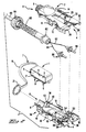
- Figure 1 is a fragmentary perspective view, shown with parts exploded apart, of a connector assembly for optical fibers adapted with means for keeping multiple keying elements.
- Figure 2 is a fragmentary perspective view of the connector assembly shown with parts exploded apart.
- Figure 3 is a rear elevation view of the means for keeping multiple keying elements.
- Figure 4 is a front elevation view of the means for keeping multiple keying elements.
- Figure 5 is a fragmentary plan view partially in section of the connector assembly and the means for keeping multiple keying elements.
- With reference to Figure 1, a connector assembly in the form of a
plug connector 86 for optical fibers is adapted with means for keeping multiple keying elements. With reference to Figure 2, theplug connector 86 includes abody portion 2 and abody portion 56. Each ofportions plug assembly latches 10,plug assembly lugs 12 and alatching arm 14 including a latching lug thereon. Half of amale shroud element 28 and half of afemale shroud element 30 are offset at opposite sides of the front end 4. A space orgap 29 is between theshroud elements - With reference to
portion 2, an exterior surface ofportion 2 includes achannel 20 and a detent 22 recessed in sides of thechannel 20. An aperture portion or keyingelement receiving passage 26 extends from the detent 22 to the interior of theportion 2. An aperture portion or keyingelement receiving passage 26′ extends from the exterior to the interior ofportion 56. - With reference to Figure 2,
optical fibers cable 60 for thefibers respective ferrules Cable 60 is provided with astrain relief 80 having an integralannular flange 82. An internally threadednut 84 is also provided. - Upon assembly of the components illustrated in Figure 2, the
ferrules respective recesses portion 56. Flanges 74, 74 of theferrules respective cavities portion 56. Theflange 82 is received in aslot 42 betweenridges Body portion 2 is assembled toportion 56, over theferrules flange 82.Latches 10 of theportion 2 engage and latch against thelugs 12 of theportion 56.Latches 10 of theportion 56 engage and latch againstcorresponding lugs 12 of theportion 2.Nut 84 is threaded onto the cable entry portions 8, 8 that are provided with external threads.Aperture portions connector assembly 86. A male shroud at the front end 4 is formed by theshroud elements shroud elements - With reference to Figure 1, the
connector assembly 86 is adapted withinterchangeable keying elements portion 96, of enlarged block form or any form that conforms in size and shape to seat in thedetent 22, and apost 98 for extending along the keying element receiving passage formed by theaperture portions keying elements respective keyways 104 extending through theportion 96 at different locations. Thus, eachkeying element keyway 104 in a different location along thechannel 20. Theconnector assembly 86 is adaptable with any one of the threekeying elements - The
keying elements connector assembly 86, and requiremeans 1 for keeping them with theconnector assembly 86 while they are not being used. Themeans 1, for example, is in the form of a cover for theconnector assembly 86, askirt 2′ of the cover encircling the front end 4 of theconnector assembly 86, anend wall 3 unitary with theskirt 2′ and extending across the front end 4 and joining with edges of theskirt 2′ , anopen end 5 of the cover along the edges of theskirt 2′ and opposite theend wall 3, connectingmeans 7 for connecting the cover to theconnector assembly 86, especially to retain themeans 1 to theconnector assembly 86 when theskirt 2′ is removed from the front end 4,interior webs gap 29 in the front end 4 to retain the cover on the front end 4, andpockets 11 external to theskirt 2′ frictionally receivingkeying elements element receiving passage connector assembly 86, whereby all of thekeying elements keying elements passage - Insertion and retraction of the
keying elements corresponding pockets 11 is accommodated. The shape of each of thepockets 11 conforms to the shape of a corresponding one of thekeying elements means 1 is chosen for flexure to accommodate insertion and retraction. Agroove 13 of eachpocket 11 communicates with the interior of thepocket 11 and permits expansion and contraction and flexure of thepocket 11 to reduce frictional resistance to insertion and extraction. Eachgroove 13 extends through toopen ends corresponding pocket 11. Thekeyway 104 of eachkeying element open end 15 for identification. A smalleropen end 17 permits the application of pressure against acorresponding post 98 of akeying element pocket 11. - The
webs open end 5 and are spaced apart. Thegap 29 intersectssides 20′, 20′ of thechannel 20, and thewebs channel 20 and frictionally engage thesides 20′, 20′ to retain the cover on theconnector assembly 86. - With reference to Figure 5, the
sides 20′, 20′ of thechannel 20 extend to the front end 4, and have outwardly flaredportions 22′, 22′ at the front end 4. Thewebs portions 20˝, 20˝ and are funneled along thechannel 20 by the outwardly flaredportions 20˝, 20˝. - A cross section profile of the front end 4 is asymmetrical, due to the
male shroud 30 and thefemale shroud 28. Theconnector assembly 86 has a symmetrical cross section profile 4′ behind of the front end 4. Theskirt 2′ extends to encircle both the asymmetrical cross section profile and the symmetrical cross section profile 4′. The friction of thewebs skirt 2′ alone is inadequate due to theskirt 2′ being symmetrical in profile, and nonconforming to the asymmetry of the front end 4. - The
connecting means 7 comprises; alanyard 19 unitary with theskirt 2′, aloop 21 at a free end of thelanyard 19 encircling the rear 6 of theconnector assembly 86, and thenut 84 larger in circumference than the circumference of theloop 21, thenut 84 being connected to the rear 6 of theconnector assembly 86 and engaged against theloop 21. With reference to Figure 2, during assembly, theferrules fibers flange 82 are passed through theloop 21, and are assembled to theportions 2, 4. Theloop 21 encircles the cable receiving portions 8, 8, and thenut 84 is assembled, to clamp theloop 21 between thenut 82 and the rear 6 of theconnector assembly 86. - Each of the discussed advantages, features and objectives of the disclosed invention exists independently and contributes to the use and importance of the invention.
Claims (7)
the connector (86) is adapted to receive the keying elements (94, 94′, 94˝) one at a time in the passage (26) (26′) and a cover(1) for the connector (86) keeps the keying elements (94, 94′, 94˝) while they are not being used in the passage (26, 26′).
webs (9, 9) extend across the cover 1 and lodge in a gap 29 in a front end (4.
the connector (86) has an axially extending channel (20) in an external surface, outwardly flared sides (22′), (22′) of the channel 20 extend to the front end (4), and the webs (9, 9) are funneled between the sides (22′, 22′) to extend along the channel (20).
the gap (29) intersects the channel (20).
the connector (86) has an axially extending channel (20) in an external surface, the gap (29) intersects sides (20′, 20′) of the channel (20), and the webs (9, 9) engage the sides (20′, 20′) of the channel 20.
a skirt (2′) of the cover (1) encircles a front end (4) of the connector (86), a lanyard (19) connects the cover (1) to the connector (86), when the skirt (2′) is removed from the front end (4) and pockets (11, 11, 11) external to the skirt (2′) frictionally receive all of the keying elements (94, 94′, 94˝) in the absence of any one of the keying elements (94, 94′, 94˝) in the passage (22, 22′).
a cross sectional profile of the front end (4) is asymmetrical, the connector 86 has a symmetrical cross section profile rearward of the front end (4), and the skirt (2′) extends to cover both profiles.
Applications Claiming Priority (2)
| Application Number | Priority Date | Filing Date | Title |
|---|---|---|---|
| US396582 | 1989-08-21 | ||
| US07/396,582 US4979792A (en) | 1989-08-21 | 1989-08-21 | Means for keeping keying elements with a connector assembly |
Publications (3)
| Publication Number | Publication Date |
|---|---|
| EP0414438A2 true EP0414438A2 (en) | 1991-02-27 |
| EP0414438A3 EP0414438A3 (en) | 1991-09-25 |
| EP0414438B1 EP0414438B1 (en) | 1994-08-03 |
Family
ID=23567835
Family Applications (1)
| Application Number | Title | Priority Date | Filing Date |
|---|---|---|---|
| EP90308943A Expired - Lifetime EP0414438B1 (en) | 1989-08-21 | 1990-08-14 | Means for keeping keying elements with a connector assembly |
Country Status (3)
| Country | Link |
|---|---|
| US (1) | US4979792A (en) |
| EP (1) | EP0414438B1 (en) |
| DE (1) | DE69011240T2 (en) |
Cited By (4)
| Publication number | Priority date | Publication date | Assignee | Title |
|---|---|---|---|---|
| EP0608026A2 (en) * | 1993-01-21 | 1994-07-27 | SIRTI S.p.A. | Multiple connector for multi-fibre optic ribbons |
| EP0859252A2 (en) * | 1997-02-12 | 1998-08-19 | The Whitaker Corporation | Improved cable strain relief |
| US7237965B2 (en) | 2003-05-02 | 2007-07-03 | Airbus Uk Limited | Fibre optic connector |
| CN106471409A (en) * | 2014-06-30 | 2017-03-01 | 耐克森公司 | The reversible MPO optical fiber connector of polarity |
Families Citing this family (104)
| Publication number | Priority date | Publication date | Assignee | Title |
|---|---|---|---|---|
| US5167542A (en) * | 1990-01-31 | 1992-12-01 | Thomas & Betts Corporation | Interconnectable components employing a multi-positionable key |
| US5041025A (en) * | 1990-01-31 | 1991-08-20 | Thomas & Betts Corporation | Interconnectable components employing a multi-positionable key |
| US5037175A (en) * | 1990-06-11 | 1991-08-06 | Amp Incorporated | Clip for dressing of fiber optic cable within confined space |
| US5119455A (en) * | 1990-11-09 | 1992-06-02 | General Motors Corporation | Fiber optic wall plate connector system |
| US5071219A (en) * | 1990-11-09 | 1991-12-10 | General Motors Corporation | Fiber optic connection system and method |
| US5091991A (en) * | 1991-02-25 | 1992-02-25 | Amp Incorporated | Optical fiber connector with alignment feature |
| US5109453A (en) * | 1991-02-25 | 1992-04-28 | Amp Incorporated | Optical fiber connector with latching beam mechanism |
| US5140663A (en) * | 1991-04-17 | 1992-08-18 | Amp Incorporated | Latching beam mechanism having plug stops for optical connector |
| US5138680A (en) * | 1991-04-17 | 1992-08-11 | Amp Incorporated | Optical fiber connector with elastomeric centering and floating alignment feature |
| US5138679A (en) * | 1991-04-17 | 1992-08-11 | Amp Incorporated | Optical fiber connector with centering and floating alignment feature |
| US5315679A (en) * | 1992-04-27 | 1994-05-24 | International Business Machines Corporation | Optical fibers duplex connector assembly |
| US5202949A (en) * | 1992-04-30 | 1993-04-13 | Amp Incorporated | Dust cover for fiber optic ferrules of optical fiber connectors |
| US5243678A (en) * | 1992-06-29 | 1993-09-07 | Amp Incorporated | Alignment cover for a fiber optic receptacle |
| US5333221A (en) * | 1992-06-30 | 1994-07-26 | The Whitaker Corporation | Universal adapter for optical connectors |
| US5289554A (en) * | 1992-09-29 | 1994-02-22 | Minnesota Mining And Manufacturing Company | Keying element for fiber connector |
| US5265181A (en) * | 1992-09-30 | 1993-11-23 | Foxconn International, Inc. | Optical fiber connector with easy changeable verification element |
| US5325455A (en) * | 1992-10-21 | 1994-06-28 | Minnesota Mining And Manufacturing Company | Fiber optic edge card connector |
| US5283849A (en) * | 1993-02-01 | 1994-02-01 | Siecor Corporation | Optical connector preassembly |
| US5329604A (en) * | 1993-02-11 | 1994-07-12 | International Business Machines Corporation | Optical fiber coupling device and optoelectronic system utilizing same |
| US5335301A (en) * | 1993-05-05 | 1994-08-02 | Methode Electronics, Inc. | Fiber optic connector with sliding key |
| US5333222A (en) * | 1993-05-14 | 1994-07-26 | Molex Incorporated | Adapter for interconnecting optical fiber connectors or the like |
| US5414790A (en) * | 1993-11-09 | 1995-05-09 | Minnesota Mining And Manufacturing Company | Actuation tool and cap for fiber optic connector |
| US5563974A (en) * | 1994-12-30 | 1996-10-08 | Minnesota Mining And Manufacturing Company | Tool for connector with cleaved optical fiber |
| US5521997A (en) * | 1995-02-28 | 1996-05-28 | The Whitaker Corporation | Rotatably polarizing keying element for a polarized connector |
| US5712938A (en) * | 1996-05-30 | 1998-01-27 | Tai Jin Mold Mfg. Co. | Optical fiber connector |
| US6017153A (en) * | 1998-05-29 | 2000-01-25 | Lucent Technologies, Inc. | Optical fiber connector with auxiliary spring |
| US6296399B1 (en) | 1999-07-02 | 2001-10-02 | Delphi Technologies, Inc. | Fiber optic connection system |
| US6599033B1 (en) * | 2000-10-30 | 2003-07-29 | Infineon Technologies Ag | Device for sealing a coupling unit for an optoelectronic component against contaminants |
| US6622356B2 (en) * | 2001-06-01 | 2003-09-23 | Delphi Technologies, Inc. | Attachment assembly for closed-loop attachments |
| US6547450B2 (en) | 2001-06-27 | 2003-04-15 | Fitel Usa Corp. | Quick-release dust cap for an optical plug |
| US6676301B2 (en) | 2001-06-28 | 2004-01-13 | International Business Machines Corporation | Enhanced optical coupler |
| US6652159B2 (en) | 2001-06-28 | 2003-11-25 | International Business Machines Corporation | Enhanced optical transceiver arrangement |
| US6516129B2 (en) | 2001-06-28 | 2003-02-04 | Jds Uniphase Corporation | Processing protective plug insert for optical modules |
| US6643447B2 (en) * | 2002-02-05 | 2003-11-04 | The Boeing Company | Fiber optic terminator apparatus and method |
| US6962445B2 (en) | 2003-09-08 | 2005-11-08 | Adc Telecommunications, Inc. | Ruggedized fiber optic connection |
| GB2423155B (en) * | 2005-02-10 | 2009-09-09 | Agilent Technologies Inc | Keyed transceiver module |
| CN2821914Y (en) * | 2005-07-02 | 2006-09-27 | 富士康(昆山)电脑接插件有限公司 | Cable connector module |
| US20070140623A1 (en) * | 2005-10-05 | 2007-06-21 | Desanti Raymond J | Optical fiber connection fitting |
| US7572065B2 (en) | 2007-01-24 | 2009-08-11 | Adc Telecommunications, Inc. | Hardened fiber optic connector |
| US7591595B2 (en) | 2007-01-24 | 2009-09-22 | Adc Telelcommunications, Inc. | Hardened fiber optic adapter |
| WO2009050781A1 (en) * | 2007-10-16 | 2009-04-23 | Mitsubishi Heavy Industries, Ltd. | Connector terminal protection cap and harness assembly |
| US7744288B2 (en) | 2007-12-11 | 2010-06-29 | Adc Telecommunications, Inc. | Hardened fiber optic connector compatible with hardened and non-hardened fiber optic adapters |
| EP3014322B1 (en) | 2013-06-27 | 2018-09-19 | CommScope Connectivity Belgium BVBA | Fiber optic cable anchoring device for use with fiber optic connectors and methods of using the same |
| US9310569B2 (en) * | 2014-02-21 | 2016-04-12 | Alliance Fiber Optic Products, Inc. | Reconfigurable fiber optic adapter |
| JP6409288B2 (en) * | 2014-03-03 | 2018-10-24 | 住友電気工業株式会社 | Optical transceiver |
| US9658409B2 (en) * | 2015-03-03 | 2017-05-23 | Senko Advanced Components, Inc. | Optical fiber connector with changeable polarity |
| US9684139B2 (en) | 2015-05-29 | 2017-06-20 | Senko Advanced Components, Inc. | Optical fiber connector with changeable gender |
| US10712507B2 (en) * | 2015-12-19 | 2020-07-14 | US Conec, Ltd | Field changeable fiber optic connector polarity keying |
| US9726830B1 (en) | 2016-06-28 | 2017-08-08 | Senko Advanced Components, Inc. | Connector and adapter system for two-fiber mechanical transfer type ferrule |
| US10228521B2 (en) | 2016-12-05 | 2019-03-12 | Senko Advanced Components, Inc. | Narrow width adapters and connectors with modular latching arm |
| US10078188B1 (en) | 2016-12-05 | 2018-09-18 | Senko Advanced Components, Inc. | Springless push/pull fiber optic connector |
| US10725248B2 (en) | 2017-01-30 | 2020-07-28 | Senko Advanced Components, Inc. | Fiber optic receptacle with integrated device therein incorporating a behind-the-wall fiber optic receptacle |
| CN113156586A (en) | 2017-01-30 | 2021-07-23 | 扇港元器件股份有限公司 | Optical connector with reversible polarity |
| US10416394B2 (en) | 2017-01-30 | 2019-09-17 | Senko Advanced Components, Inc. | Fiber optic receptacle with integrated device therein |
| US11333836B2 (en) | 2017-01-30 | 2022-05-17 | Senko Advanced Components, Inc. | Adapter for optical connectors |
| US10185100B2 (en) | 2017-01-30 | 2019-01-22 | Senko Advanced Components, Inc | Modular connector and adapter assembly using a removable anchor device |
| US10444444B2 (en) | 2017-01-30 | 2019-10-15 | Senko Advanced Components, Inc. | Remote release tab connector assembly |
| US10754098B2 (en) | 2017-04-07 | 2020-08-25 | Senko Advanced Components, Inc. | Behind the wall optical connector with reduced components |
| US10209461B2 (en) | 2017-04-07 | 2019-02-19 | Senko Advanced Components | Behind the wall optical connector with reduced components |
| US10989884B2 (en) | 2017-04-07 | 2021-04-27 | Senko Advanced Components, Inc. | Behind the wall optical connector with reduced components |
| US10359583B2 (en) | 2017-04-07 | 2019-07-23 | Senko Advanced Components, Inc. | Behind the wall optical connector with reduced components |
| US10718910B2 (en) | 2017-05-03 | 2020-07-21 | Senko Advanced Components, Inc | Field terminated ruggedized fiber optic connector system |
| US10146016B1 (en) | 2017-05-10 | 2018-12-04 | Senko Advanced Components, Inc | MPO micro-latchlock connector |
| US10401576B2 (en) | 2017-05-10 | 2019-09-03 | Senko Advanced Components, Inc. | MPO micro-latch-lock connector |
| US10295759B2 (en) | 2017-05-18 | 2019-05-21 | Senko Advanced Components, Inc. | Optical connector with forward-biasing projections |
| US10359576B2 (en) | 2017-06-15 | 2019-07-23 | Senko Advanced Components, Inc. | SC low profile connector with optional boot |
| US11300746B2 (en) | 2017-06-28 | 2022-04-12 | Corning Research & Development Corporation | Fiber optic port module inserts, assemblies and methods of making the same |
| US11187859B2 (en) | 2017-06-28 | 2021-11-30 | Corning Research & Development Corporation | Fiber optic connectors and methods of making the same |
| US10359577B2 (en) | 2017-06-28 | 2019-07-23 | Corning Research & Development Corporation | Multiports and optical connectors with rotationally discrete locking and keying features |
| US11668890B2 (en) | 2017-06-28 | 2023-06-06 | Corning Research & Development Corporation | Multiports and other devices having optical connection ports with securing features and methods of making the same |
| EP4170400A1 (en) | 2017-06-28 | 2023-04-26 | Corning Optical Communications LLC | Multiports having connection ports formed in the shell and associated securing features |
| US11822133B2 (en) | 2017-07-14 | 2023-11-21 | Senko Advanced Components, Inc. | Ultra-small form factor optical connector and adapter |
| US10718911B2 (en) | 2017-08-24 | 2020-07-21 | Senko Advanced Components, Inc. | Ultra-small form factor optical connectors using a push-pull boot receptacle release |
| US10281669B2 (en) | 2017-07-14 | 2019-05-07 | Senko Advance Components, Inc. | Ultra-small form factor optical connectors |
| US10641972B2 (en) | 2017-08-17 | 2020-05-05 | Senko Advanced Components, Inc | Anti-jam alignment sleeve holder or connector housing for a ferrule assembly |
| US10444442B2 (en) | 2017-11-03 | 2019-10-15 | Senko Advanced Components, Inc. | MPO optical fiber connector |
| US11002923B2 (en) | 2017-11-21 | 2021-05-11 | Senko Advanced Components, Inc. | Fiber optic connector with cable boot release having a two-piece clip assembly |
| WO2019183070A2 (en) | 2018-03-19 | 2019-09-26 | Senko Advanced Components, Inc. | Removal tool for removing a plural of micro optical connectors from an adapter interface |
| EP3776038A4 (en) | 2018-03-28 | 2022-01-19 | Senko Advanced Components, Inc. | Small form factor fiber optic connector with multi-purpose boot |
| US11041993B2 (en) | 2018-04-19 | 2021-06-22 | Senko Advanced Components, Inc. | Fiber optic adapter with removable insert for polarity change and removal tool for the same |
| US10921528B2 (en) | 2018-06-07 | 2021-02-16 | Senko Advanced Components, Inc. | Dual spring multi-fiber optic connector |
| CN112088327A (en) | 2018-07-15 | 2020-12-15 | 扇港元器件股份有限公司 | Ultra-small optical connector and adapter |
| US10444441B1 (en) | 2018-08-10 | 2019-10-15 | Senko Advanced Components, Inc. | Pivotable housing for a fiber optic connector |
| US11073664B2 (en) | 2018-08-13 | 2021-07-27 | Senko Advanced Components, Inc. | Cable boot assembly for releasing fiber optic connector from a receptacle |
| US10921530B2 (en) | 2018-09-12 | 2021-02-16 | Senko Advanced Components, Inc. | LC type connector with push/pull assembly for releasing connector from a receptacle using a cable boot |
| US10921531B2 (en) | 2018-09-12 | 2021-02-16 | Senko Advanced Components, Inc. | LC type connector with push/pull assembly for releasing connector from a receptacle using a cable boot |
| CN112955797B (en) | 2018-09-12 | 2022-11-11 | 扇港元器件股份有限公司 | LC-type connector with clip-on push/pull tab for releasing the connector from a receptacle with a cable boot |
| US11806831B2 (en) | 2018-11-21 | 2023-11-07 | Senko Advanced Components, Inc. | Fixture and method for polishing fiber optic connector ferrules |
| US11175464B2 (en) | 2018-11-25 | 2021-11-16 | Senko Advanced Components, Inc. | Open ended spring body for use in an optical fiber connector |
| US11579379B2 (en) | 2019-03-28 | 2023-02-14 | Senko Advanced Components, Inc. | Fiber optic adapter assembly |
| US11340406B2 (en) | 2019-04-19 | 2022-05-24 | Senko Advanced Components, Inc. | Small form factor fiber optic connector with resilient latching mechanism for securing within a hook-less receptacle |
| US11314024B2 (en) | 2019-06-13 | 2022-04-26 | Senko Advanced Components, Inc. | Lever actuated latch arm for releasing a fiber optic connector from a receptacle port and method of use |
| CN114600018B (en) | 2019-07-23 | 2024-04-09 | 扇港元器件有限公司 | Ultra-small receptacle for receiving a fiber optic connector opposite a ferrule assembly |
| US11294133B2 (en) | 2019-07-31 | 2022-04-05 | Corning Research & Development Corporation | Fiber optic networks using multiports and cable assemblies with cable-to-connector orientation |
| US11353664B1 (en) | 2019-08-21 | 2022-06-07 | Senko Advanced Components, Inc. | Fiber optic connector |
| US11487073B2 (en) | 2019-09-30 | 2022-11-01 | Corning Research & Development Corporation | Cable input devices having an integrated locking feature and assemblies using the cable input devices |
| EP3805827A1 (en) | 2019-10-07 | 2021-04-14 | Corning Research & Development Corporation | Fiber optic terminals and fiber optic networks having variable ratio couplers |
| US11520111B2 (en) | 2019-11-13 | 2022-12-06 | Senko Advanced Components, Inc. | Fiber optic connector |
| US11650388B2 (en) | 2019-11-14 | 2023-05-16 | Corning Research & Development Corporation | Fiber optic networks having a self-supporting optical terminal and methods of installing the optical terminal |
| US11604320B2 (en) | 2020-09-30 | 2023-03-14 | Corning Research & Development Corporation | Connector assemblies for telecommunication enclosures |
| US11927810B2 (en) | 2020-11-30 | 2024-03-12 | Corning Research & Development Corporation | Fiber optic adapter assemblies including a conversion housing and a release member |
| US11686913B2 (en) | 2020-11-30 | 2023-06-27 | Corning Research & Development Corporation | Fiber optic cable assemblies and connector assemblies having a crimp ring and crimp body and methods of fabricating the same |
| US11880076B2 (en) | 2020-11-30 | 2024-01-23 | Corning Research & Development Corporation | Fiber optic adapter assemblies including a conversion housing and a release housing |
| US11947167B2 (en) | 2021-05-26 | 2024-04-02 | Corning Research & Development Corporation | Fiber optic terminals and tools and methods for adjusting a split ratio of a fiber optic terminal |
Citations (4)
| Publication number | Priority date | Publication date | Assignee | Title |
|---|---|---|---|---|
| US4376565A (en) * | 1981-02-17 | 1983-03-15 | Amp Incorporated | Electrical connector keying means |
| US4408813A (en) * | 1981-09-04 | 1983-10-11 | Noma Canada Ltd. | Multiple outlet and cover therefor |
| US4773881A (en) * | 1987-05-21 | 1988-09-27 | Amp Incorporated | Keying system for connector assemblies |
| EP0339876A1 (en) * | 1988-04-25 | 1989-11-02 | The Whitaker Corporation | Connector assembly with movable shroud protection |
Family Cites Families (6)
| Publication number | Priority date | Publication date | Assignee | Title |
|---|---|---|---|---|
| US3129993A (en) * | 1961-03-08 | 1964-04-21 | Joseph I Ross | Hermaphroditic electrical connectors |
| US3387252A (en) * | 1966-07-13 | 1968-06-04 | Square D Co | Waterproof cover assembly for electric sockets |
| US4258970A (en) * | 1979-03-05 | 1981-03-31 | The Bendix Corporation | Electrical cable and molded protection cap assembly |
| US4645295A (en) * | 1980-02-04 | 1987-02-24 | Allied Corporation | Fiber optic connector |
| US4365858A (en) * | 1981-03-03 | 1982-12-28 | The Bendix Corporation | Molded protection cap |
| US4515434A (en) * | 1983-03-09 | 1985-05-07 | Allied Corporation | Fiber optic connector |
-
1989
- 1989-08-21 US US07/396,582 patent/US4979792A/en not_active Expired - Lifetime
-
1990
- 1990-08-14 DE DE69011240T patent/DE69011240T2/en not_active Expired - Fee Related
- 1990-08-14 EP EP90308943A patent/EP0414438B1/en not_active Expired - Lifetime
Patent Citations (4)
| Publication number | Priority date | Publication date | Assignee | Title |
|---|---|---|---|---|
| US4376565A (en) * | 1981-02-17 | 1983-03-15 | Amp Incorporated | Electrical connector keying means |
| US4408813A (en) * | 1981-09-04 | 1983-10-11 | Noma Canada Ltd. | Multiple outlet and cover therefor |
| US4773881A (en) * | 1987-05-21 | 1988-09-27 | Amp Incorporated | Keying system for connector assemblies |
| EP0339876A1 (en) * | 1988-04-25 | 1989-11-02 | The Whitaker Corporation | Connector assembly with movable shroud protection |
Non-Patent Citations (1)
| Title |
|---|
| FEINWERKTECHNIK & MESSTECHNIK, vol. 98, no. 4, April 1990, pages 175-177, Munich, DE; K. WEBER: "FDDI Lichtwellenleiter - LAN Aufbau und Komponenten" * |
Cited By (6)
| Publication number | Priority date | Publication date | Assignee | Title |
|---|---|---|---|---|
| EP0608026A2 (en) * | 1993-01-21 | 1994-07-27 | SIRTI S.p.A. | Multiple connector for multi-fibre optic ribbons |
| EP0859252A2 (en) * | 1997-02-12 | 1998-08-19 | The Whitaker Corporation | Improved cable strain relief |
| EP0859252A3 (en) * | 1997-02-12 | 1998-10-07 | The Whitaker Corporation | Improved cable strain relief |
| US7237965B2 (en) | 2003-05-02 | 2007-07-03 | Airbus Uk Limited | Fibre optic connector |
| CN106471409A (en) * | 2014-06-30 | 2017-03-01 | 耐克森公司 | The reversible MPO optical fiber connector of polarity |
| CN106471409B (en) * | 2014-06-30 | 2018-08-28 | 耐克森公司 | The reversible MPO optical fiber connector of polarity |
Also Published As
| Publication number | Publication date |
|---|---|
| DE69011240T2 (en) | 1995-03-23 |
| EP0414438A3 (en) | 1991-09-25 |
| DE69011240D1 (en) | 1994-09-08 |
| US4979792A (en) | 1990-12-25 |
| EP0414438B1 (en) | 1994-08-03 |
Similar Documents
| Publication | Publication Date | Title |
|---|---|---|
| EP0414438A2 (en) | Means for keeping keying elements with a connector assembly | |
| EP0475415B1 (en) | Multiple pole electrical connector | |
| CA1068796A (en) | Electrical connector assembly having a coupling nut and housing | |
| US5121455A (en) | Fiber optic connector | |
| US7845859B2 (en) | Ferrule assembly and methods thereof | |
| US5217190A (en) | Panel yoke | |
| US6059461A (en) | Optical fiber connector assembly | |
| EP0685750A1 (en) | Connector for connecting an optical fiber cable | |
| DE3775804D1 (en) | FAST CONNECTOR, IN PARTICULAR FOR USE WITH HOSE COUPLINGS. | |
| GB2241794A (en) | Connector with an overconnector assembly for a pair of optical fiber connectors | |
| EP0848187A3 (en) | Cord end stopper | |
| US4406507A (en) | Electrical connector insert | |
| US5069639A (en) | Metal terminal retaining mechanism for connector | |
| US4386816A (en) | Electrical connector insert assembly | |
| US4636020A (en) | Insert for an electrical connector | |
| EP0015657A2 (en) | Optical fibre connector | |
| US4093332A (en) | Power connector | |
| US4182546A (en) | Multiple connector for optical fibres | |
| EP1701187A3 (en) | Hermaphroditic insert member for connectors | |
| US5395246A (en) | Connector having multiple keying features | |
| US4387944A (en) | Electrical connector insert | |
| US4387943A (en) | Electrical connector having front or rear releasable and removable contacts | |
| US6000966A (en) | Electrical connector with contact terminal locking | |
| EP0366345A2 (en) | Optical connector | |
| US5017157A (en) | Receptacle for cable connector with locking mechanism and electric shielding property |
Legal Events
| Date | Code | Title | Description |
|---|---|---|---|
| PUAI | Public reference made under article 153(3) epc to a published international application that has entered the european phase |
Free format text: ORIGINAL CODE: 0009012 |
|
| 17P | Request for examination filed |
Effective date: 19901227 |
|
| AK | Designated contracting states |
Kind code of ref document: A2 Designated state(s): DE FR GB IT NL |
|
| PUAL | Search report despatched |
Free format text: ORIGINAL CODE: 0009013 |
|
| AK | Designated contracting states |
Kind code of ref document: A3 Designated state(s): DE FR GB IT NL |
|
| 17Q | First examination report despatched |
Effective date: 19920707 |
|
| RAP1 | Party data changed (applicant data changed or rights of an application transferred) |
Owner name: THE WHITAKER CORPORATION |
|
| GRAA | (expected) grant |
Free format text: ORIGINAL CODE: 0009210 |
|
| AK | Designated contracting states |
Kind code of ref document: B1 Designated state(s): DE FR GB IT NL |
|
| ET | Fr: translation filed | ||
| REF | Corresponds to: |
Ref document number: 69011240 Country of ref document: DE Date of ref document: 19940908 |
|
| ITF | It: translation for a ep patent filed |
Owner name: PROROGA CONCESSA IN DATA: 15.12.94;GUZZI E RAVIZZ |
|
| PLBE | No opposition filed within time limit |
Free format text: ORIGINAL CODE: 0009261 |
|
| STAA | Information on the status of an ep patent application or granted ep patent |
Free format text: STATUS: NO OPPOSITION FILED WITHIN TIME LIMIT |
|
| 26N | No opposition filed | ||
| PGFP | Annual fee paid to national office [announced via postgrant information from national office to epo] |
Ref country code: GB Payment date: 19980702 Year of fee payment: 9 |
|
| PGFP | Annual fee paid to national office [announced via postgrant information from national office to epo] |
Ref country code: NL Payment date: 19990630 Year of fee payment: 10 |
|
| PG25 | Lapsed in a contracting state [announced via postgrant information from national office to epo] |
Ref country code: GB Free format text: LAPSE BECAUSE OF NON-PAYMENT OF DUE FEES Effective date: 19990814 |
|
| GBPC | Gb: european patent ceased through non-payment of renewal fee |
Effective date: 19990814 |
|
| PG25 | Lapsed in a contracting state [announced via postgrant information from national office to epo] |
Ref country code: NL Free format text: LAPSE BECAUSE OF NON-PAYMENT OF DUE FEES Effective date: 20010301 |
|
| NLV4 | Nl: lapsed or anulled due to non-payment of the annual fee |
Effective date: 20010301 |
|
| PGFP | Annual fee paid to national office [announced via postgrant information from national office to epo] |
Ref country code: FR Payment date: 20040804 Year of fee payment: 15 |
|
| PGFP | Annual fee paid to national office [announced via postgrant information from national office to epo] |
Ref country code: DE Payment date: 20040831 Year of fee payment: 15 |
|
| PG25 | Lapsed in a contracting state [announced via postgrant information from national office to epo] |
Ref country code: IT Free format text: LAPSE BECAUSE OF NON-PAYMENT OF DUE FEES;WARNING: LAPSES OF ITALIAN PATENTS WITH EFFECTIVE DATE BEFORE 2007 MAY HAVE OCCURRED AT ANY TIME BEFORE 2007. THE CORRECT EFFECTIVE DATE MAY BE DIFFERENT FROM THE ONE RECORDED. Effective date: 20050814 |
|
| PG25 | Lapsed in a contracting state [announced via postgrant information from national office to epo] |
Ref country code: DE Free format text: LAPSE BECAUSE OF NON-PAYMENT OF DUE FEES Effective date: 20060301 |
|
| PG25 | Lapsed in a contracting state [announced via postgrant information from national office to epo] |
Ref country code: FR Free format text: LAPSE BECAUSE OF NON-PAYMENT OF DUE FEES Effective date: 20060428 |
|
| REG | Reference to a national code |
Ref country code: FR Ref legal event code: ST Effective date: 20060428 |