EP0413092B1 - Osteosynthesehilfsmittel - Google Patents
Osteosynthesehilfsmittel Download PDFInfo
- Publication number
- EP0413092B1 EP0413092B1 EP90109312A EP90109312A EP0413092B1 EP 0413092 B1 EP0413092 B1 EP 0413092B1 EP 90109312 A EP90109312 A EP 90109312A EP 90109312 A EP90109312 A EP 90109312A EP 0413092 B1 EP0413092 B1 EP 0413092B1
- Authority
- EP
- European Patent Office
- Prior art keywords
- stay bar
- auxiliary
- foot
- link
- brace
- Prior art date
- Legal status (The legal status is an assumption and is not a legal conclusion. Google has not performed a legal analysis and makes no representation as to the accuracy of the status listed.)
- Expired - Lifetime
Links
Images
Classifications
-
- A—HUMAN NECESSITIES
- A61—MEDICAL OR VETERINARY SCIENCE; HYGIENE
- A61B—DIAGNOSIS; SURGERY; IDENTIFICATION
- A61B17/00—Surgical instruments, devices or methods, e.g. tourniquets
- A61B17/56—Surgical instruments or methods for treatment of bones or joints; Devices specially adapted therefor
- A61B17/58—Surgical instruments or methods for treatment of bones or joints; Devices specially adapted therefor for osteosynthesis, e.g. bone plates, screws, setting implements or the like
- A61B17/60—Surgical instruments or methods for treatment of bones or joints; Devices specially adapted therefor for osteosynthesis, e.g. bone plates, screws, setting implements or the like for external osteosynthesis, e.g. distractors, contractors
- A61B17/64—Devices extending alongside the bones to be positioned
- A61B17/6425—Devices extending alongside the bones to be positioned specially adapted to be fitted across a bone joint
Definitions
- the invention relates to an osteosynthesis aid for fixation of the ankle in connection with an external fixator.
- a triangular brace i. H. a so-called frame assembly has become known as a fixator, which carries a plate for supporting the foot in a right-angled position. Height, side and angle adjustment of the plate is not provided and also not possible.
- the invention is therefore based on the object of providing an osteosynthesis aid which serves to fix the ankle and which, in conjunction with an external, unilateral fixator, enables the foot to be fixed in any position which may be selected.
- an osteosynthesis aid which connects to the usually lower end of a unilateral fixator that is commercially available today, for example as described in US Pat. No. 4,312,336, the fixator being able to be attached in any position, then via a longitudinal support rod adjustable in length leads to a foot support plate, the foot support plate connecting to the longitudinal support rod via a cross support rod.
- the footrest plate connects to the transverse support rod via a ball joint, the footrest plate can be tilted about its transverse axis and adjustable about its longitudinal axis and can thus be aligned of the fixator are adjusted and at the same time precisely adjusted to the desired foot position of the patient.
- the longitudinal support rod can be constructed from several individual parts which can be screwed together, so that the length adjustment is possible.
- the ball joints provided according to the invention can be locked by simple toggle locks, but other locking means are also possible here without the invention being restricted in any way, but care must be taken to ensure that once the osteosynthesis aid according to the invention has been connected, the position once selected individual parts can be locked.
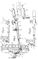
- a fixator 1 In the drawing, an end part of a fixator 1 is shown, from which the bone screws or nails 14 can be seen.
- a connecting clip 2 At this end part of a fixator 1 there is a connecting clip 2, which can consist of two half-shells 15 and 16, these two half-shells 15, 16 being securely connectable to one another via a screw connection 17.
- the connecting clip 2 connects to one end of a longitudinal support rod 3.
- This longitudinal support rod 3 consists in the illustrated embodiment of three parts 10, 11 and 12, wherein the parts 12 and 11 can be screwed together. If part 11 is not used, it can be seen that part 10 can connect directly to part 12.
- the length adjustability of the longitudinal support rod 3 is made possible in that the part 10 is formed like a sleeve at its end 18 and is equipped here with a clamp closure 19.
- the other end of the longitudinal support rod 3 carries a cross support rod 4, which is also adjustable in length, in that this cross support rod 4 consists of two rod parts 20 and 21, the rod part 20, similar to the rod part 10, has a sleeve which via clamping means on the part 21 can be set.
- the cross holding rod 4 carries a foot support plate 5 which has a padding 22, which padding 22 is directed towards the sole of the patient's foot.
- the cross bar 4 connects to the footrest plate 5 via a ball joint 8, which can be locked via the toggle lock 23.
- the foot support plate 5 can be rotated about several axes, so that it can be adjusted to the position and inclination of the patient's foot.
- the transverse holding rod 4 also connects to the longitudinal holding rod 3 via a ball joint 7 and the longitudinal holding rod 3 in turn connects to the connecting clip 2 via a ball joint 6. All these ball joints 6, 7, 8 are rigid.
- Fig. 3 it is shown that it is possible to interpose a "90 ° elbow" 9 between the end of the support rod 3 facing the connecting clip 2, so that it is possible, despite a parallel orientation of the longitudinal support rod 3, for example to the shin of the Patients to connect the longitudinal support rod 3 to a fixator 1, which is arranged transversely to the longitudinal axis of the lower leg bones.
- connection clip 2 requires a special adaptation to the fixator used in each case and that a connection clip 2 is shown in the present description and drawing to clarify the invention, which in connection with one of the US-PS 43 12 336 known fixator can be used.
Description
- Die Erfindung bezieht sich auf ein Osteosynthesehilfsmittel zur Fixation des Fußgelenkes in Verbindung mit einem äußeren Fixateur.
- Äußere Fixateure, insbesondere metallische Hilfsmittel, dienen der Fixation einer Fraktur. Hierdurch soll die Festlegung der Frakturenden in der genau gewünschten und erforderlichen Stellung erfolgen und über lange Zeit diese Stellung aufrechterhalten werden. Solche heute üblichen, unilateralen Fixateure sind beispielsweise Gegenstand der US-PS 43 12 336.
- Bei der Fixation der Unterschenkelknochen treten aber dadurch Probleme auf, daß der Fuß bei Flachlagerung des Patienten in eine Spitzfußstellung fällt, was es erforderlich macht, daß dieser Fuß ständig beübt werden muß. Ein Festlegen des Fußes in der gewünschten Normalstellung durch einen starren Verband ist nicht möglich, da hierdurch die Durchblutung gehindert wird und häufig auch Verletzungen im Bereich des Fußes vorliegen, die den Verband ausschließen. Liegen zudem Gehirnbeeinträchtigungen vor, darf ebenfalls ein Beüben des Fußes nicht stattfinden.
- Aus der Literaturstelle "Manual der Osteosynthese", New York 1977, ist eine Dreieckverstrebung, d. h. eine sogenannte Rahmenmontage als Fixateur bekanntgeworden, die eine Platte zur Stützung des Fußes in Rechtwinkelstellung trägt. Eine Höhen-, Seiten- und Winkeleinstellung der Platte ist nicht vorgesehen und auch nicht möglich.
- Der Erfindung liegt daher die Aufgabe zugrunde, ein zur Fixation des Fußgelenkes dienendes Osteosynthesehilfsmittel zu schaffen, das in Verbindung mit einem äußeren, unilateralen Fixateur die Möglichkeit gibt, den Fuß in einer beliebig wählbaren Stellung zu fixieren.
- Diese der Erfindung zugrundeliegende Aufgabe wird durch die Lehre des Hauptanspruches gelöst.
- Mit anderen Worten ausgedrückt wird ein Osteosynthesehilfsmittel vorgeschlagen, das an das üblicherweise untere Ende eines heute handelsüblichen, unilateralen Fixateurs, beispielsweise wie er in der US-PS 43 12 336 beschrieben ist, anschließt, wobei der Fixateur in beliebiger Lage angebracht sein kann, dann über eine in ihrer Länge einstellbare Längshaltestange zu einer Fußstützplatte führt, wobei die Fußstützplatte über eine Querhaltestange an der Längshaltestange anschließt. Dadurch, daß die Fußstützplatte über ein Kugelgelenk an der Querhaltestange anschließt, ist die Fußstützplatte um ihre Querachse neigbar und um ihre Längsachse einstellbar und kann damit der Ausrichtung des Fixateurs angepaßt werden und gleichzeitig auf die gewünschte beliebige Fußstellung des Patienten genau eingestellt werden.
- In gewissen Einsatzfällen kommt es vor, daß die untere Klemmbacke des Fixateurs am Unterschenkel auch quer ausgerichtet angebracht werden muß. Um in einem solchen Fall auch das erfindungsgemäße Osteosynthesehilfsmittel anschließen zu können, wird ein 90° - Winkelstück vorgeschlagen, das zwischen das obere Ende der Längshaltestange und die Anschlußklammer eingeschaltet werden kann, so daß nunmehr auch die Anschlußklammer wiederum an den quergerichteten Fixateur angepaßt ist.
- Um die Längshaltestange jeder beliebigen Länge anpassen zu können und damit jeder beliebigen Stellung des Fixateurs am Bein des Patienten, kann die Längshal testange aus mehreren Einzelteilen aufgebaut sein, die miteinander verschraubbar sind, so daß dadurch die Längenregulierung möglich ist.
- Die erfindungsgemäß vorgesehenen Kugelgelenke können über einfache Knebelverschlüsse verstarrt werden, aber hier sind auch andere Verschlußmittel möglich, ohne daß hierauf die Erfindung in irgendeiner Weise beschränkt ist, aber es muß dafür Sorge getragen werden, daß nach Anschluß des erfindungsgemäßen Osteosynthesehilfsmittel s die einmal gewählte Stellung der einzelnen Teile verstarrt werden kann.
- Ausführungsbeispiele der Erfindung werden nachfolgend anhand der Zeichnung erläutert. Die Zeichnung zeigt dabei in
- Fig. 1
- schaubildlich ein Osteosynthesehilfsmittel, in
- Fig. 2
- schematisch den Aufbau des Osteosynthesehilfsmittels gemäß der Erfindung und in
- Fig. 3
- eine durch ein Winkelstück ergänzte Ausführungsform.
- In der Zeichnung ist ein Endteil eines Fixateurs 1 dargestellt, von dem die Knochenschrauben oder Nägel 14 erkennbar sind. An dieses Endteil eines Fixateurs 1 schließt eine Anschlußklammer 2 an, die aus zwei Halbschalen 15 und 16 bestehen kann, wobei diese beiden Halbschalen 15, 16 über eine Schraubverbindung 17 fest miteinander verbindbar sind.
- Die Anschlußklammer 2 schließt an das eine Ende einer Längshaltestange 3 an. Diese Längshaltestange 3 besteht bei dem dargestellten Ausführungsbeispiel aus drei Teilen 10, 11 und 12, wobei die Teile 12 und 11 miteinander verschraubbar sind. Wird das Teil 11 nicht eingesetzt, ist erkennbar, daß das Teil 10 unmittelbar an das Teil 12 anschließen kann. Außerdem wird die Längenverstellbarkeit der Längshaltestange 3 dadurch ermöglicht, daß das Teil 10 an seinem Ende 18 muffenartig ausgebildet ist und hier mit einem Klemmverschluß 19 ausgerüstet ist.
- Das andere Ende der Längshaltestange 3 trägt eine Querhaltestange 4, die ebenfalls längenverstellbar ausgebildet ist, dadurch, daß diese Querhaltestange 4 aus zwei Stangenteilen 20 und 21 besteht, wobei das Stangenteil 20 ähnlich wie das Stangenteil 10 eine Muffe aufweist, die über Klemmittel an dem Teil 21 festgelegt werden kann.
- Die Querhaltestange 4 trägt eine Fußstützplatte 5, die eine Polsterung 22 besitzt, wobei diese Polsterung 22 zur Fußsohle des Patienten hin gerichtet ist. Die Querhaltestange 4 schließt an die Fußstützplatte 5 über ein Kugelgelenk 8 an, das über den Knebelverschluß 23 verriegelbar ist. Über dieses Kugelgelenk 8 kann die Fußstützplatte 5 um mehrere Achsen gedreht werden, so daß sie der Stellung und Neigung des Fußes des Patienten anpaßbar ist.
- Die Querhaltestange 4 schließt aber auch über ein Kugelgelenk 7 an die Längshaltestange 3 an und die Längshaltestange 3 schließt wiederum über ein Kugelgelenk 6 an die Anschlußklammer 2 an. Alle diese Kugelgelenke 6, 7, 8 sind verstarrbar.
- Dieser vorbeschriebene Aufbau geht schematisch deutlicher aus Fig. 2 hervor.
- In Fig. 3 ist dargestellt, daß es möglich ist, zwischen das der Anschlußklammer 2 zugewandte Ende der Haltestange 3 ein "90° - Winkelstück" 9 zwischenzuschließen, so daß es möglich ist, trotz einer parallelen Ausrichtung der Längshaltestange 3, beispielsweise zum Schienbein des Patienten, die Längshaltestange 3 an einen Fixateur 1 anzuschließen, der quer zur Längsachse der Unterschenkelknochen angeordnet ist.
- Es sei darauf hingewiesen, daß die Ausbildung der Anschlußklammer 2 eine speziale Anpassung an den jeweils eingesetzten Fixateur notwendig macht und daß zur Verdeutlichung der Erfindung in der vorliegenden Beschreibung und Zeichnung eine Anschlußklammer 2 dargestellt ist, die in Verbindung mit einem aus der US-PS 43 12 336 bekannten Fixateur einsetzbar ist.
Claims (6)
- Osteosynthesehilfsmittel zur Fixation des Fußgelenkes in Verbindung mit einem äußeren Fixateur, gekennzeichnet durcha) eine Anschlußklammer (2) zur Festlegung des Hilfsmittels an einen Fixateur (1),b) eine längenveränderliche Längshaltestange (3), die einenendes an der Anschlußklammer (2) anschließt und anderenendes mittelbar eine Fußstützplatte (5) trägt,c) eine Querhaltestange (4), die einenendes die Fußstützplatte (5) trägt und anderenendes an der Längshaltestange (3) anschließt,d) Kugelgelenke (6, 7, 8) als Anschlußstellen zwischenwobei die Kugelgelenke (6, 7, 8) arretierbar sind.1) der Längshaltestange (3) und der Anschlußklammer (2),2) der Längshaltestange (3) und der Querhaltestange (4),3) der Querhaltestange (4) und der Fußstützplatte (5),
- Osteosynthesehilfsmittel nach Anspruch 1, dadurch gekennzeichnet, daß zwischen der Anschlußklammer (2) und der Längshaltestange (3) ein "90° - Winkelstück" (9) anbringbar ist.
- Osteosynthesehilfsmittel nach Anspruch 1 oder 2, dadurch gekennzeichnet, daß die Querhaltestange (4) längenveränderlich ist.
- Osteosynthesehilfsmittel nach einem oder mehreren der vorhergehenden Ansprüche, dadurch gekennzeichnet, daß die Längshaltestange (3) aus mehreren miteinander verbindbaren Teilen (10, 11, 12) besteht und stufenlos längenverstellbar ist.
- Osteosynthesehilfsmittel nach einem oder mehreren der vorhergehenden Ansprüche, dadurch gekennzeichnet, daß die Fußstützplatte (5) gepolstert ist.
- Osteosynthesehilfsmittel nach Anspruch 1, dadurch gekennzeichnet, daß die Anschlußklammer (2) aus zwei fest miteinander verbindbaren Halbschalen (15, 16) besteht.
Applications Claiming Priority (2)
| Application Number | Priority Date | Filing Date | Title |
|---|---|---|---|
| DE3926893 | 1989-08-16 | ||
| DE3926893A DE3926893C1 (de) | 1989-08-16 | 1989-08-16 |
Publications (3)
| Publication Number | Publication Date |
|---|---|
| EP0413092A2 EP0413092A2 (de) | 1991-02-20 |
| EP0413092A3 EP0413092A3 (en) | 1991-05-02 |
| EP0413092B1 true EP0413092B1 (de) | 1994-06-22 |
Family
ID=6387133
Family Applications (1)
| Application Number | Title | Priority Date | Filing Date |
|---|---|---|---|
| EP90109312A Expired - Lifetime EP0413092B1 (de) | 1989-08-16 | 1990-05-17 | Osteosynthesehilfsmittel |
Country Status (5)
| Country | Link |
|---|---|
| US (1) | US4998935A (de) |
| EP (1) | EP0413092B1 (de) |
| AT (1) | ATE107493T1 (de) |
| DE (2) | DE3926893C1 (de) |
| ES (1) | ES2055828T3 (de) |
Families Citing this family (22)
| Publication number | Priority date | Publication date | Assignee | Title |
|---|---|---|---|---|
| US5454810A (en) * | 1990-02-05 | 1995-10-03 | Pohl; Anthony P. | External fixation device |
| FR2667781B1 (fr) * | 1990-10-12 | 1994-01-21 | Materiel Orthopedique Cie Gle | Attelle externe de fixation et reduction de fractures osseuses. |
| US5080661A (en) * | 1991-04-18 | 1992-01-14 | Hollister Incorporated | Fixation pin entry site dressing and method |
| FR2692472B1 (fr) * | 1992-06-19 | 1994-09-09 | Tornier Sa | Appareil externe pour la reconstitution de la partie supérieure de l'humérus. |
| US6171309B1 (en) | 1995-02-15 | 2001-01-09 | Acumed, Inc. | External fixator for repairing fractures of distal radius and wrist |
| US6162224A (en) * | 1995-02-15 | 2000-12-19 | Acumed, Inc. | External fixator for repairing fractures of distal radius and wrist |
| US5743898A (en) * | 1995-05-12 | 1998-04-28 | Electro-Biology, Inc. | Method and apparatus for external fixation of small bones |
| US5662650A (en) | 1995-05-12 | 1997-09-02 | Electro-Biology, Inc. | Method and apparatus for external fixation of large bones |
| US5976125A (en) * | 1995-08-29 | 1999-11-02 | The Cleveland Clinic Foundation | External distractor/fixator for the management of fractures and dislocations of interphalangeal joints |
| DE59813925D1 (en) | 1998-05-19 | 2007-04-12 | Synthes Gmbh | Backe für monolaterales externes fixationssystem für traumatologie und orthopädie |
| US7004943B2 (en) * | 2002-02-04 | 2006-02-28 | Smith & Nephew, Inc. | Devices, systems, and methods for placing and positioning fixation elements in external fixation systems |
| US7048735B2 (en) * | 2002-02-04 | 2006-05-23 | Smith & Nephew | External fixation system |
| US7758582B2 (en) * | 2002-06-14 | 2010-07-20 | Smith & Nephew, Inc. | Device and methods for placing external fixation elements |
| US7608074B2 (en) * | 2003-01-10 | 2009-10-27 | Smith & Nephew, Inc. | External fixation apparatus and method |
| US20040260223A1 (en) * | 2003-06-17 | 2004-12-23 | Roukis Thomas S. | External fixation device |
| US7422593B2 (en) * | 2005-12-08 | 2008-09-09 | Ebi, L.P. | External fixation system |
| US7955333B2 (en) | 2007-11-15 | 2011-06-07 | Yeager David A | Method of preparing a patient's leg in need of treatment, for ambulation |
| US8192434B2 (en) * | 2008-05-02 | 2012-06-05 | Huebner Randall J | External fixation and foot-supporting device |
| US9770272B2 (en) | 2012-12-12 | 2017-09-26 | Wright Medical Technology, Inc. | Orthopedic compression/distraction device |
| US9155561B2 (en) | 2013-03-06 | 2015-10-13 | Stryker Trauma Sa | Mini-rail external fixator |
| US9962188B2 (en) | 2013-10-29 | 2018-05-08 | Cardinal Health 247. Inc. | External fixation system and methods of use |
| US10531896B2 (en) | 2015-08-10 | 2020-01-14 | Stryker European Holdings I, Llc | Distraction tube with wire clamp |
Family Cites Families (15)
| Publication number | Priority date | Publication date | Assignee | Title |
|---|---|---|---|---|
| US594865A (en) * | 1897-12-07 | Fracture apparatus | ||
| US1863188A (en) * | 1929-08-28 | 1932-06-14 | Harwood G Clash | Surgical appliance |
| US2393831A (en) * | 1942-12-29 | 1946-01-29 | Stader Otto | Bone splint |
| US2406987A (en) * | 1943-01-04 | 1946-09-03 | Anderson Roger | Fracture splint |
| US2391537A (en) * | 1943-09-27 | 1945-12-25 | Anderson Roger | Ambulatory rotating reduction and fixation splint |
| US3086522A (en) * | 1961-06-26 | 1963-04-23 | Harley R Frohmader | Orthopedic braces |
| GB1582133A (en) * | 1976-04-30 | 1980-12-31 | Nat Res Dev | Orthopaedic fracture fixing apparatus |
| ES253459Y (es) * | 1978-11-10 | 1982-04-16 | Fijador clinico externo, de elevada estabilidad, para reduc-cion de fracturas. | |
| US4336796A (en) * | 1980-08-04 | 1982-06-29 | Andrews E Trent | Adjustable lower extremity splint with single point suspension |
| US4407277A (en) * | 1980-10-27 | 1983-10-04 | Ellison Arthur E | Surgical apparatus |
| US4554915A (en) * | 1983-03-08 | 1985-11-26 | Richards Medical Company | Bone fixation frame |
| IT1181490B (it) * | 1984-12-18 | 1987-09-30 | Orthofix Srl | Apparecchio ortopedico per la fissazione esterna assiale,ad ampia gamma di adattabilita' |
| US4771768A (en) * | 1986-12-16 | 1988-09-20 | United States Manufacturing Company | Controlled motion ankle fracture walker |
| DE3701533A1 (de) * | 1987-01-21 | 1988-08-04 | Medi System Gmbh | Osteosynthesehilfsmittel |
| US4947835A (en) * | 1989-04-05 | 1990-08-14 | Dynasplint Systems, Inc. | Adjustable splint assembly |
-
1989
- 1989-08-16 DE DE3926893A patent/DE3926893C1/de not_active Expired - Lifetime
-
1990
- 1990-05-17 DE DE59006194T patent/DE59006194D1/de not_active Expired - Fee Related
- 1990-05-17 AT AT90109312T patent/ATE107493T1/de active
- 1990-05-17 ES ES90109312T patent/ES2055828T3/es not_active Expired - Lifetime
- 1990-05-17 EP EP90109312A patent/EP0413092B1/de not_active Expired - Lifetime
- 1990-08-03 US US07/562,479 patent/US4998935A/en not_active Expired - Fee Related
Also Published As
| Publication number | Publication date |
|---|---|
| DE3926893C1 (de) | 1991-04-11 |
| ATE107493T1 (de) | 1994-07-15 |
| US4998935A (en) | 1991-03-12 |
| DE59006194D1 (de) | 1994-07-28 |
| ES2055828T3 (es) | 1994-09-01 |
| EP0413092A2 (de) | 1991-02-20 |
| EP0413092A3 (en) | 1991-05-02 |
Similar Documents
| Publication | Publication Date | Title |
|---|---|---|
| EP0413092B1 (de) | Osteosynthesehilfsmittel | |
| DE69828711T2 (de) | Querverbindungsklemme für Wirbelsäulenstäbe | |
| DE69815683T2 (de) | Distraktionsvorrichtung | |
| AT389992B (de) | Vorrichtung zur externen fixierung von knochenfragmenten | |
| DE19802229C2 (de) | Plattenförmiger Riegel zur Ruhigstellung einer Fraktur des Beckens | |
| DE60034489T2 (de) | Vorrichtung zur externen transpedikularen wirbelsäulenfixierung | |
| DE3229313C2 (de) | Vorrichtung zur äußeren Fixierung gebrochener Knochen | |
| DE3917916C1 (de) | ||
| DE69636821T2 (de) | Kreuzverbindung mit variabeler länge und winkel | |
| EP0452451B1 (de) | Pedikelschraube und korrektur- und haltevorrichtung mit einer solchen pedikelschraube | |
| DE60210502T2 (de) | Knochenimplantat mit polyaxialem kopf | |
| DE60030256T2 (de) | Vorrichtung zur äusseren fixierung von knochen | |
| DE60125928T2 (de) | Äusserer einwegfixateur | |
| DE2203787C3 (de) | Fixator für Diaphysenbruch | |
| DE2834891C3 (de) | Fixateur zum Fixieren von Knochen oder Knochenbruchstücken, insbesondere Wirbeln | |
| DE60013370T2 (de) | Hüftgelenkstütze | |
| EP0546460B1 (de) | Osteosynthesehilfsmittel bei pertrochantärem Oberschenkelhalsbruch | |
| DE3201066A1 (de) | Extremitaeteneinstell- und haltevorrichtung | |
| WO1999029247A1 (en) | Method and apparatus for external fixation of an ankle | |
| EP0383419A1 (de) | Orthopädische Fixiereinrichtung | |
| US10973550B2 (en) | Monoplanar hinged adjustable external fixator for bone fixation and distraction | |
| DE3805178C2 (de) | ||
| DE3302078C2 (de) | ||
| DE3032237A1 (de) | Implantat zur operativen korrektur von seitlichen wirbelsaeulenverkruemmungen | |
| EP0705582B1 (de) | Kniegelenkorthese |
Legal Events
| Date | Code | Title | Description |
|---|---|---|---|
| PUAI | Public reference made under article 153(3) epc to a published international application that has entered the european phase |
Free format text: ORIGINAL CODE: 0009012 |
|
| AK | Designated contracting states |
Kind code of ref document: A2 Designated state(s): AT BE CH DE ES FR GB IT LI NL SE |
|
| PUAL | Search report despatched |
Free format text: ORIGINAL CODE: 0009013 |
|
| AK | Designated contracting states |
Kind code of ref document: A3 Designated state(s): AT BE CH DE ES FR GB IT LI NL SE |
|
| 17P | Request for examination filed |
Effective date: 19910404 |
|
| RAP3 | Party data changed (applicant data changed or rights of an application transferred) |
Owner name: PENNIG, DIETMAR, DR. MED. |
|
| RAP1 | Party data changed (applicant data changed or rights of an application transferred) |
Owner name: PENNIG, DIETMAR, DR. MED. |
|
| 17Q | First examination report despatched |
Effective date: 19930817 |
|
| GRAA | (expected) grant |
Free format text: ORIGINAL CODE: 0009210 |
|
| AK | Designated contracting states |
Kind code of ref document: B1 Designated state(s): AT BE CH DE ES FR GB IT LI NL SE |
|
| REF | Corresponds to: |
Ref document number: 107493 Country of ref document: AT Date of ref document: 19940715 Kind code of ref document: T |
|
| REF | Corresponds to: |
Ref document number: 59006194 Country of ref document: DE Date of ref document: 19940728 |
|
| ET | Fr: translation filed | ||
| REG | Reference to a national code |
Ref country code: ES Ref legal event code: FG2A Ref document number: 2055828 Country of ref document: ES Kind code of ref document: T3 |
|
| ITF | It: translation for a ep patent filed |
Owner name: ING. DORIGUZZI ANDREA |
|
| GBT | Gb: translation of ep patent filed (gb section 77(6)(a)/1977) |
Effective date: 19940901 |
|
| EAL | Se: european patent in force in sweden |
Ref document number: 90109312.0 |
|
| PLBE | No opposition filed within time limit |
Free format text: ORIGINAL CODE: 0009261 |
|
| STAA | Information on the status of an ep patent application or granted ep patent |
Free format text: STATUS: NO OPPOSITION FILED WITHIN TIME LIMIT |
|
| 26N | No opposition filed | ||
| PGFP | Annual fee paid to national office [announced via postgrant information from national office to epo] |
Ref country code: GB Payment date: 19970508 Year of fee payment: 8 |
|
| PGFP | Annual fee paid to national office [announced via postgrant information from national office to epo] |
Ref country code: SE Payment date: 19970512 Year of fee payment: 8 |
|
| PGFP | Annual fee paid to national office [announced via postgrant information from national office to epo] |
Ref country code: ES Payment date: 19970519 Year of fee payment: 8 |
|
| PGFP | Annual fee paid to national office [announced via postgrant information from national office to epo] |
Ref country code: CH Payment date: 19970521 Year of fee payment: 8 |
|
| PGFP | Annual fee paid to national office [announced via postgrant information from national office to epo] |
Ref country code: DE Payment date: 19970524 Year of fee payment: 8 |
|
| PGFP | Annual fee paid to national office [announced via postgrant information from national office to epo] |
Ref country code: AT Payment date: 19970528 Year of fee payment: 8 |
|
| PGFP | Annual fee paid to national office [announced via postgrant information from national office to epo] |
Ref country code: BE Payment date: 19970529 Year of fee payment: 8 |
|
| PGFP | Annual fee paid to national office [announced via postgrant information from national office to epo] |
Ref country code: FR Payment date: 19970530 Year of fee payment: 8 |
|
| PGFP | Annual fee paid to national office [announced via postgrant information from national office to epo] |
Ref country code: NL Payment date: 19970531 Year of fee payment: 8 |
|
| PG25 | Lapsed in a contracting state [announced via postgrant information from national office to epo] |
Ref country code: GB Free format text: LAPSE BECAUSE OF NON-PAYMENT OF DUE FEES Effective date: 19980517 Ref country code: AT Free format text: LAPSE BECAUSE OF NON-PAYMENT OF DUE FEES Effective date: 19980517 |
|
| PG25 | Lapsed in a contracting state [announced via postgrant information from national office to epo] |
Ref country code: SE Free format text: LAPSE BECAUSE OF NON-PAYMENT OF DUE FEES Effective date: 19980518 Ref country code: ES Free format text: LAPSE BECAUSE OF NON-PAYMENT OF DUE FEES Effective date: 19980518 |
|
| PG25 | Lapsed in a contracting state [announced via postgrant information from national office to epo] |
Ref country code: LI Free format text: LAPSE BECAUSE OF NON-PAYMENT OF DUE FEES Effective date: 19980531 Ref country code: FR Free format text: LAPSE BECAUSE OF NON-PAYMENT OF DUE FEES Effective date: 19980531 Ref country code: CH Free format text: LAPSE BECAUSE OF NON-PAYMENT OF DUE FEES Effective date: 19980531 Ref country code: BE Free format text: LAPSE BECAUSE OF NON-PAYMENT OF DUE FEES Effective date: 19980531 |
|
| BERE | Be: lapsed |
Owner name: PENNIG DIETMAR Effective date: 19980531 |
|
| PG25 | Lapsed in a contracting state [announced via postgrant information from national office to epo] |
Ref country code: NL Free format text: LAPSE BECAUSE OF NON-PAYMENT OF DUE FEES Effective date: 19981201 |
|
| GBPC | Gb: european patent ceased through non-payment of renewal fee |
Effective date: 19980517 |
|
| REG | Reference to a national code |
Ref country code: CH Ref legal event code: PL |
|
| EUG | Se: european patent has lapsed |
Ref document number: 90109312.0 |
|
| NLV4 | Nl: lapsed or anulled due to non-payment of the annual fee |
Effective date: 19981201 |
|
| PG25 | Lapsed in a contracting state [announced via postgrant information from national office to epo] |
Ref country code: DE Free format text: LAPSE BECAUSE OF NON-PAYMENT OF DUE FEES Effective date: 19990302 |
|
| REG | Reference to a national code |
Ref country code: FR Ref legal event code: ST |
|
| REG | Reference to a national code |
Ref country code: ES Ref legal event code: FD2A Effective date: 20000403 |
|
| PG25 | Lapsed in a contracting state [announced via postgrant information from national office to epo] |
Ref country code: IT Free format text: LAPSE BECAUSE OF NON-PAYMENT OF DUE FEES;WARNING: LAPSES OF ITALIAN PATENTS WITH EFFECTIVE DATE BEFORE 2007 MAY HAVE OCCURRED AT ANY TIME BEFORE 2007. THE CORRECT EFFECTIVE DATE MAY BE DIFFERENT FROM THE ONE RECORDED. Effective date: 20050517 |