EP0412221A2 - Apparatus for centering a transducer over a track of a magnetic disk - Google Patents
Apparatus for centering a transducer over a track of a magnetic disk Download PDFInfo
- Publication number
- EP0412221A2 EP0412221A2 EP89312299A EP89312299A EP0412221A2 EP 0412221 A2 EP0412221 A2 EP 0412221A2 EP 89312299 A EP89312299 A EP 89312299A EP 89312299 A EP89312299 A EP 89312299A EP 0412221 A2 EP0412221 A2 EP 0412221A2
- Authority
- EP
- European Patent Office
- Prior art keywords
- arm
- transducer
- track
- over
- disk
- Prior art date
- Legal status (The legal status is an assumption and is not a legal conclusion. Google has not performed a legal analysis and makes no representation as to the accuracy of the status listed.)
- Granted
Links
Images

Classifications
-
- G—PHYSICS
- G11—INFORMATION STORAGE
- G11B—INFORMATION STORAGE BASED ON RELATIVE MOVEMENT BETWEEN RECORD CARRIER AND TRANSDUCER
- G11B5/00—Recording by magnetisation or demagnetisation of a record carrier; Reproducing by magnetic means; Record carriers therefor
- G11B5/48—Disposition or mounting of heads or head supports relative to record carriers ; arrangements of heads, e.g. for scanning the record carrier to increase the relative speed
- G11B5/58—Disposition or mounting of heads or head supports relative to record carriers ; arrangements of heads, e.g. for scanning the record carrier to increase the relative speed with provision for moving the head for the purpose of maintaining alignment of the head relative to the record carrier during transducing operation, e.g. to compensate for surface irregularities of the latter or for track following
- G11B5/596—Disposition or mounting of heads or head supports relative to record carriers ; arrangements of heads, e.g. for scanning the record carrier to increase the relative speed with provision for moving the head for the purpose of maintaining alignment of the head relative to the record carrier during transducing operation, e.g. to compensate for surface irregularities of the latter or for track following for track following on disks
-
- G—PHYSICS
- G11—INFORMATION STORAGE
- G11B—INFORMATION STORAGE BASED ON RELATIVE MOVEMENT BETWEEN RECORD CARRIER AND TRANSDUCER
- G11B5/00—Recording by magnetisation or demagnetisation of a record carrier; Reproducing by magnetic means; Record carriers therefor
- G11B5/48—Disposition or mounting of heads or head supports relative to record carriers ; arrangements of heads, e.g. for scanning the record carrier to increase the relative speed
- G11B5/4806—Disposition or mounting of heads or head supports relative to record carriers ; arrangements of heads, e.g. for scanning the record carrier to increase the relative speed specially adapted for disk drive assemblies, e.g. assembly prior to operation, hard or flexible disk drives
- G11B5/4873—Disposition or mounting of heads or head supports relative to record carriers ; arrangements of heads, e.g. for scanning the record carrier to increase the relative speed specially adapted for disk drive assemblies, e.g. assembly prior to operation, hard or flexible disk drives the arm comprising piezoelectric or other actuators for adjustment of the arm
-
- G—PHYSICS
- G11—INFORMATION STORAGE
- G11B—INFORMATION STORAGE BASED ON RELATIVE MOVEMENT BETWEEN RECORD CARRIER AND TRANSDUCER
- G11B5/00—Recording by magnetisation or demagnetisation of a record carrier; Reproducing by magnetic means; Record carriers therefor
- G11B5/48—Disposition or mounting of heads or head supports relative to record carriers ; arrangements of heads, e.g. for scanning the record carrier to increase the relative speed
- G11B5/54—Disposition or mounting of heads or head supports relative to record carriers ; arrangements of heads, e.g. for scanning the record carrier to increase the relative speed with provision for moving the head into or out of its operative position or across tracks
- G11B5/55—Track change, selection or acquisition by displacement of the head
- G11B5/5521—Track change, selection or acquisition by displacement of the head across disk tracks
- G11B5/5552—Track change, selection or acquisition by displacement of the head across disk tracks using fine positioning means for track acquisition separate from the coarse (e.g. track changing) positioning means
Definitions
- This invention relates to apparatus for centering transducers over tracks on magnetic disks.
- One method of positioning the data heads over the tracks on the disks which uses a closed loop feedback circuit is the dedicated servo method.
- the dedicated servo method one data head and one disk in the disk drive system are dedicated to the task of acquiring position information.
- the dedicated data head is referred to as the servo head and the dedicated disk is referred to as the servo disk.
- the servo head is connected to a designated servo arm which is coupled to the same actuator as the other arms.
- the servo head is held over the centre of a desired track on the servo disk by a closed loop servo system which utilises feedback from specially written data on the servo disk to position properly the actuator. Since the other arms are rigidly attached to the actuator, they follow the servo arm and are positioned over the desired tracks on their respective disks.
- the servo head is in the closed loop feedback circuit with the servo disk
- the other data heads and other disks do not have the benefit of a separate closed loop feedback system to assure that they are properly positioned.
- the other disks and heads must maintain their original position with respect to the servo head and the servo disk over extended periods of time. Maintaining this position is often difficult because of shifts in the relative head position due to temperature extremes and mechanical wear. If all the data heads, arms and disks do not maintain their positions relative to the servo head and the servo disk, off track errors will result. Off track errors reduce read margins and may cause data errors.
- U.S. Patent Application Serial No. 937,270 One method for correcting the problem of position shifting due to temperature extremes and mechanical wear is disclosed in U.S. Patent Application Serial No. 937,270.
- a heating element such as a resistor
- heat is generated which expands and contracts the material in the arm, thereby bending the arm so as to move the head in an arcuate path which is substantially transverse to the tracks on the disk.
- a feedback loop is constructed around the head in which a parameter of the read back signal is compared to a desired value to form an error term. The error term is then used to set the power level which is applied to the resistor. In this way, the data head on each arm can be independently centered within the tracks on the disk.
- a second disadvantage is that the method of comparing a parameter of the read signal to a desired value is very prone to error.
- the characteristics of read signals from tracks on magnetic disks vary greatly from disk drive system to disk drive system and also vary depending on a number of head and disk parameters.
- the characteristics of read signals vary greatly from the inner radius to the outer radius on any particular disk. Therefore, it is very difficult to establish a proper value for the sensed parameter for comparison.
- an apparatus for centering a transducer over a track of a magnetic disk characterised by comprising: an arm having a first end attached to an actuator for rotating the arm and a second end attached to a slider which carries the transducer, and having first and second arm portions extending between the first and second ends and being spaced apart at the first end; and heating means for selectively applying thermal energy to the first and second arm portions to cause selected thermal expansion in the first and second arm portions causing the arm portions to bend and move the slider along an arcuate path in a plane substantially parallel to the disk and substantially transverse to the track to position the transducer over the centre of the track.
- an apparatus for controlling tracking of a plurality of transducers over tracks on a plurality of magnetic disks, at least one transducer corresponding to each disk the apparatus being characterised by comprising: a plurality of arms each having a first end attached to an actuator for rotating the arm and a second end attached to a slider which carries one of the transducers, and each arm having first and second arm portions extending between the first and second ends and being spaced apart at the first end; and heating means for selectively applying and removing thermal energy to the first and second arm portions of each arm for causing selected thermal expansion in the first and second arm portions causing the arm portions to bend and move the corresponding slider along an arcuate path in a plane substantially parallel to the corresponding disk and substantially transverse to the track to position the transducer over the centre of the track.
- an apparatus for positioning a transducer over the centre of a track in a magnetic disk having an arm with a first end attached to an actuator for rotating the arm, and a second end attached to a slider carrying a transducer, the arm including first and second arm portions extending between the first and second ends, the arm portions being spaced at the first end of the arm characterised by comprising: first means for selectively applying thermal energy to the first arm portion to cause the arm to bend and move the slider along an arcuate path in a first direction to position the transducer over the centre of the track; and second means for selectively applying thermal energy to the second arm portion to cause the arm to bend and move the slider along the arcuate path in a second direction to position the transducer over the centre of the track.
- the heating means comprises a first heating element carried by the or each first arm portion, and a second heating element carried by the or each second arm portion.
- the apparatus may include position indicating means for providing a position signal indicating when the transducer on the or selected one of the arms is tracking off centre, and heat controlling means for selectively varying the amount of heat applied to the first and second arm portions as a function of the position signal.
- the apparatus preferably is in combination with one or more disks the or each disk having a plurality of sectors for containing information, the position signal, in operation, including position data indicating the distance the transducer on the or selected one of the arms is from the centre of the respective track, the position data being recorded on at least one of the sectors on the or the corresponding disk.
- the position signal may comprise a modulated signal representing the position data which the transducer on the or a selected one of the arms passes over as the transducer passes over the sector containing the position data.
- the position indicating means in one embodiment, includes a demodulator for demodulating the modulated signal to produce a demodulated position signal.
- the heat controlling means preferably comprises: compensation means for compensating the position signal, means for determining a correction value based on the compensated position signal, the correction value representing a distance that the transducer on the or a selected one of the arms is from the centre of the track, and a heat element power supply which varies power delivered to the first heating element and the second heating element as a function of the correction value.
- the apparatus may include arm selection means for selecting an arm to be corrected.
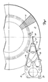
- Figure 1 shows one embodiment of apparatus according to the present invention.
- a thermally compensated fixed arm 10 is shown positioned over a magnetic disk 12.
- the disk 12 includes a plurality of zones, including a position zone 14, and a plurality of tracks 16.
- the arm 10 includes a free end 18 and an attached end 20.
- An extender 22 is attached to the free end 18 and to a slider 23 ( Figure 2).
- the slider 23 is attached to a transducer 24.
- the attached end 20 of the arm 10 is attached to an actuator (not shown) which pivots the arm 10 to move the transducer 24 from track to track on the disk 12.
- the arm 10 also includes a first arm portion 26 and a second arm portion 28.
- the arm portions 26, 28 extend between the free end 18 and the attached end 20 of the arm 10.
- the first arm portion 26 is in spaced apart relation to the second arm portion 28 at the attached end 20.
- First and second heating elements 30, 32 are attached to the first arm portion 26 and the second arm position 28, respectively.
- the heating elements 30, 32 are resistors and are embedded in the arm portions 26, 28, respectively.
- the arm 10, and particularly the arm portions 26, 28 thereof, is made of a material such as metal, plastics or a composite material which expands upon heating and contracts upon cooling. Therefore, when the first heating element 30 heats up, the arm portion 26 expands as a function of the co-efficient of linear expansion for the particular material of which it is formed. Consequently, the transducer 24 moves in a direction across the particular track 16 over which it is positioned. When the heating element 30 cools, and thus when the arm portion 26 of the arm 10 cools, the arm portion 26 contracts as a function of the co- efficient of linear expansion and the transducer 24 moves across the particular track 16 in the opposite direction.
- the arm portion 28 expands as a function of the co-efficient of linear expansion for the particular material of which it is formed. Consequently, the transducer 24 moves in a direction across the particular track 16 over which it is positioned.
- the heating element 32 cools, and thus when the arm portion 28 of the arm 10 cools, the arm portion 28 contracts as a function of the co-efficient of linear expansion and the transducer 24 moves across the track in the opposite direction.
- the range of movement described above (which is typically in terms of micro-inches) and the particular direction of movement depends on the geometry of the arm 10, the material from which the arm 10 is made and the temperature rise or drop in the arm portions 26, 28.
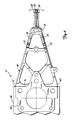
- Figure 2 illustrates the motion of the arm 10 during operation.
- the arm 10 is shown essentially as a triangle 34 having a fixed base 36 and two variable length legs.
- the variable length legs comprise the arm portion 26 and the arm portion 28, respectively.
- the extender 22, which is attached to the transducer 24 by the slider 23, is positioned near the inter-section of the arm portions 26, 28. It is assumed that the base 36 is fixed because an actuator 94 does not move once it pivots the arm 10 so that the transducer 24 is positioned over a particular track 16 on the disk 12.
- the arm portion 26 expands and the resulting motion is essentially along an arc 38.
- the movement along the arc 38 results from the arm portion 28 pivoting about a point 40 where the arm portion 28 is attached to the base 36.
- FIG. 3 shows the arm 10 as used in a feedback control circuit.
- the feedback control circuit includes a controller 44, a heating element power supply 46, a head selector 48, a data head demodulator 50 and a switch 52.
- the feedback control circuit operates to centre the transducer 24 over the particular track 16 on the disk 12 over which it is travelling.
- the transducer 24 With each revolution of the disk 12, the transducer 24 (see Figure 1) passes over the position zone 14. Information is written in the position zone 14 such that, when it is de-coded, it provides a voltage which is proportional to the distance that the transducer 24 has moved from the centre of the track 16. Therefore, with each revolution of the disk 12, a small burst of position information is read from the disk 12.
- the arm 10 in Figure 3 is part of a large disk drive system including a plurality of arms. Therefore the head selector 48 selects one of a plurality of arms to be re-positioned.
- the position information read from the disk 12 by the transducer 24 is supplied to the data head demodulator 50.
- the data head demodulator 50 de-codes the position information retrieved from the disk 12 and provides an analog voltage which is proportional to the distance that the transducer 24 has moved from the centre of the track 16.
- the analog switch 52 is closed, the analog voltage provided by the data head demodulator 50 is provided to an analog-to-digital (A/D) converter 54.
- the A/D converter 54 provides a digital signal to the controller 44, the digital signal being representative of the analog voltage provided by the data head demodulator 50.
- the controller 44 determines that the digital signal provided by the A/D converter 54 is non-zero, then the controller 44 must determine a correction value. To determine the correction value, the controller 44 performs compensation calculations for a compensator 56 which outputs the correction value based on those calculations. The parameters of the compensator 56 are chosen to compensate the digital signal provided by the A/D converter 54 so that the feedback control circuit has a desired response.
- the compensator 56 is a digital filter. The controller 44 performs digital filter calculations for the digital filter thereby determining the correction value.
- the correction value from the controller 44 is a voltage which is supplied to the power supply 46.
- the heating element power supply 46 controls the heating elements 30, 32 independently to produce an amount of heat proportional to the desired correction value.
- the power supply 46 produces a power output which corresponds to the correction value provided by the controller 44.
- the heating elements 30, 32 convert the power supplied to them into heat, thereby heating and causing expansion in the arm portions 26, 28, respectively. Therefore, the correction value which is provided to the power supply 46 in volts is converted to micro-inches of movement through the inter-action of the power supply 46, the heating elements 30, 32 and the arm portions 26, 28.
- the power supply 46 controls the heating elements 30, 32 independently, power will be supplied to only one heating element (30 or 32) to correct the position of the arm 10. In other words, power will be supplied to the heating element 30 for correction in one direction, and power will be supplied to the heating element 32 for correction in the opposite direction. Moreover, where no correction is required, there will be no power supplied to either of the heating elements 30, 32.
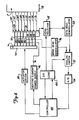
- Figure 4 is a block diagram of a control circuit for controlling arm position in a disk drive system with a plurality of disks and a plurality of arms.
- the disk drive system includes a spindle 58 which supports the plurality of magnetic disks 60, 62, 64, 66, 68, 70, 72, 74, 76 (collectively referred to as disks 60 - 76).
- the disks 60 - 76 are mounted for rotation with the spindle 58.
- the disk drive system also includes a plurality of arms 78, 80, 82, 84, 86, 88, 90, 92 (collectively referred to as arms 78 - 92) each of which is of substantially the same construction as the arm 10 shown in Figures 1 to 3.
- Each of the arms 78 - 92 is provided with a pair of transducers 24 (with the exception of the arm 86 which has only one transducer 24) which fly over surfaces on the disks 60 to 76.
- the arms 78 - 92 are mounted to the actuator 94 which operates to pivot the arms 78 - 92 from track to track on the disks 60 - 76.
- the control circuit includes the controller 44, the heating element power supply 46, the head selector 48, the data head demodulator 50, the analog switch 52, the A/D converter 54, a servo head demodulator 96, an actuator driver 98 and input/output (I/O) logic 100.
- the arm 86 serves as the servo arm, and the transducer associated with the arm 86 reads servo head position information from the servo disk 68.
- the servo head position information is provided to the servo head demodulator 96 which de-codes the position information and provides an analog voltage indicating the position of the servo arm 86 to the analog switch 52.
- the controller 44 provides a signal to the I/O logic 100 causing the analog switch 52 to pass the analog voltage provided by the servo head demodulator 96 to the A/D converter 54.
- the A/D converter 54 provides a digital signal to the controller 44 which represents the analog voltage provided by the servo head demodulator 96.
- the controller 44 calculates a correction value and provides it to the actuator driver 98.
- the actuator driver 98 causes the actuator 94 to rotate in response to the correction value to maintain the transducer 24 on the servo arm 86 over the centre of the particular track 16 over which it is travelling.
- a signal from the servo head demodulator 96 indicates that the position zones 14 on the disks 60 - 66 and 70 - 76 is about to pass the transducers 24 on the arms 78 - 84 and 88 - 92.
- the I/O logic 100 switches the head selector 48 to read position information from a desired arm 78 - 84 or 88 - 92.
- the data head demodulator 50 de-codes the information provided by the selected arm into a voltage proportional to the distance that the transducer 24 on the selected arm has moved from the centre of the track 16.
- the controller 44 samples this de-coded information by causing the I/O logic 100 to switch the analog switch 52 so that it passes the signal provided by the data head demodulator 50. After the information is converted to a digital value by the A/D converter 54, the controller 44 performs digital filter computations and determines a correction value for the selected arm.
- the correction value is provided to the power supply 46 which supplies enough power to the desired heating element in the selected arm to produce an amount of heat which is proportional to the desired correction value.
- the I/O logic 100 causes the head selector 48 to choose a different arm for correction.
- the position of the transducer on the selected arm is sampled by the controller 44 and corrected through the power supply 46.
- the head selector 48 chooses another arm for correction. Once all of the arms have been sampled and corrected, the sequence of selection by the head selector 48 is repeated. This results in a constant sample rate for each of the arms.
- the present invention allows a plurality of transducers 24 on a plurality of arms 78 - 92 to be accurately positioned over the centre of tracks 16 on respective magnetic disks. Since each arm has heating elements 30, 32, each of which are positioned in a separate respective arm portion 26, 28, the power output of the correction system is zero when no correction is required. Also, even where some correction is required, but where it is not large, if a component in the feedback loop fails thereby causing power supplied to the heating elements 30, 32 to be interrupted, no large off track errors will result.
- position correction with the present invention does not rely on a comparison of a parameter of the read signal with a desired parameter. This substantially reduces the probability of error.
- the present invention includes compensation, such as a digital filter, to shape the response in the feedback control loop. Therefore, the parameters of the compensator can be chosen so that the control loop has a desirable response.
Abstract
Description
- This invention relates to apparatus for centering transducers over tracks on magnetic disks.
- In drive systems, there is typically a stack of disks which are spaced apart and mounted on a spindle. Data heads, which carry transducers that read and write information on the disks are attached to arms which extend between the disks so that the data heads fly over the disks. The arms are attached to an actuator which is moved to position the data heads over data tracks on the disks. If the data heads are to read and write information reliably on the disks, the transducers must be centered over the data tracks. Therefore, a closed loop feedback system is desirable for positioning the data heads over the tracks.
- One method of positioning the data heads over the tracks on the disks which uses a closed loop feedback circuit, is the dedicated servo method. In the dedicated servo method, one data head and one disk in the disk drive system are dedicated to the task of acquiring position information. The dedicated data head is referred to as the servo head and the dedicated disk is referred to as the servo disk. The servo head is connected to a designated servo arm which is coupled to the same actuator as the other arms. The servo head is held over the centre of a desired track on the servo disk by a closed loop servo system which utilises feedback from specially written data on the servo disk to position properly the actuator. Since the other arms are rigidly attached to the actuator, they follow the servo arm and are positioned over the desired tracks on their respective disks.
- Although the servo head is in the closed loop feedback circuit with the servo disk, the other data heads and other disks do not have the benefit of a separate closed loop feedback system to assure that they are properly positioned. Thus, in order to function properly, the other disks and heads must maintain their original position with respect to the servo head and the servo disk over extended periods of time. Maintaining this position is often difficult because of shifts in the relative head position due to temperature extremes and mechanical wear. If all the data heads, arms and disks do not maintain their positions relative to the servo head and the servo disk, off track errors will result. Off track errors reduce read margins and may cause data errors.
- One method for correcting the problem of position shifting due to temperature extremes and mechanical wear is disclosed in U.S. Patent Application Serial No. 937,270. In this method, a heating element, such as a resistor, is embedded in one side of each of the arms. When power is applied to the resistor, heat is generated which expands and contracts the material in the arm, thereby bending the arm so as to move the head in an arcuate path which is substantially transverse to the tracks on the disk. A feedback loop is constructed around the head in which a parameter of the read back signal is compared to a desired value to form an error term. The error term is then used to set the power level which is applied to the resistor. In this way, the data head on each arm can be independently centered within the tracks on the disk.
- Whilst this system has significant advantages, there are several short comings. First, it is desirable to be able to move the data head in both directions along the arcuate path. Therefore, even when no correction is required, a certain power level must be maintained in the resistor to allow movement in both directions. This results in power being dissipated even when no correction is required. Also, since power must be maintained even when no correction is required, in the event that a component failure causes loss of power to the resistor, large off track errors will result.
- A second disadvantage is that the method of comparing a parameter of the read signal to a desired value is very prone to error. The characteristics of read signals from tracks on magnetic disks vary greatly from disk drive system to disk drive system and also vary depending on a number of head and disk parameters. In addition, the characteristics of read signals vary greatly from the inner radius to the outer radius on any particular disk. Therefore, it is very difficult to establish a proper value for the sensed parameter for comparison.
- Finally, the feedback look disclosed in U.S. Patent Application Serial No. 937,270 does not contain compensation. In order to achieve a desirable system response, some type of compensation is required.
- Therefore, there is a continuing need for apparatus which will centre transducers over tracks on disks in disk drive systems.
- According to one aspect of the present invention there is provided an apparatus for centering a transducer over a track of a magnetic disk characterised by comprising: an arm having a first end attached to an actuator for rotating the arm and a second end attached to a slider which carries the transducer, and having first and second arm portions extending between the first and second ends and being spaced apart at the first end; and heating means for selectively applying thermal energy to the first and second arm portions to cause selected thermal expansion in the first and second arm portions causing the arm portions to bend and move the slider along an arcuate path in a plane substantially parallel to the disk and substantially transverse to the track to position the transducer over the centre of the track.
- According to another aspect of the present invention there is provided an apparatus for controlling tracking of a plurality of transducers over tracks on a plurality of magnetic disks, at least one transducer corresponding to each disk, the apparatus being characterised by comprising: a plurality of arms each having a first end attached to an actuator for rotating the arm and a second end attached to a slider which carries one of the transducers, and each arm having first and second arm portions extending between the first and second ends and being spaced apart at the first end; and heating means for selectively applying and removing thermal energy to the first and second arm portions of each arm for causing selected thermal expansion in the first and second arm portions causing the arm portions to bend and move the corresponding slider along an arcuate path in a plane substantially parallel to the corresponding disk and substantially transverse to the track to position the transducer over the centre of the track.
- According to a further aspect of the present invention there is provided an apparatus for positioning a transducer over the centre of a track in a magnetic disk, the apparatus having an arm with a first end attached to an actuator for rotating the arm, and a second end attached to a slider carrying a transducer, the arm including first and second arm portions extending between the first and second ends, the arm portions being spaced at the first end of the arm characterised by comprising: first means for selectively applying thermal energy to the first arm portion to cause the arm to bend and move the slider along an arcuate path in a first direction to position the transducer over the centre of the track; and second means for selectively applying thermal energy to the second arm portion to cause the arm to bend and move the slider along the arcuate path in a second direction to position the transducer over the centre of the track.
- In one embodiment the heating means comprises a first heating element carried by the or each first arm portion, and a second heating element carried by the or each second arm portion. The apparatus may include position indicating means for providing a position signal indicating when the transducer on the or selected one of the arms is tracking off centre, and heat controlling means for selectively varying the amount of heat applied to the first and second arm portions as a function of the position signal.
- The apparatus preferably is in combination with one or more disks the or each disk having a plurality of sectors for containing information, the position signal, in operation, including position data indicating the distance the transducer on the or selected one of the arms is from the centre of the respective track, the position data being recorded on at least one of the sectors on the or the corresponding disk.
- In operation the position signal may comprise a modulated signal representing the position data which the transducer on the or a selected one of the arms passes over as the transducer passes over the sector containing the position data.
- The position indicating means, in one embodiment, includes a demodulator for demodulating the modulated signal to produce a demodulated position signal.
- The heat controlling means preferably comprises: compensation means for compensating the position signal, means for determining a correction value based on the compensated position signal, the correction value representing a distance that the transducer on the or a selected one of the arms is from the centre of the track, and a heat element power supply which varies power delivered to the first heating element and the second heating element as a function of the correction value.
- The apparatus may include arm selection means for selecting an arm to be corrected.
- The invention is illustrated, merely by way of example, in the accompanying drawings, in which:-
- Figure 1 is a top view of an arm of apparatus according to the present invention positioned over a magnetic disk where a portion of the arm is cut away to show heating elements;
- Figure 2 is an enlarged diagram of the arm shown in Figure 1;
- Figure 3 shows the arm of Figure 1 in a block diagram of a feedback loop; and
- Figure 4 shows a block diagram of a feedback control loop used with a plurality of arms of apparatus according to the present invention.
- Figure 1 shows one embodiment of apparatus according to the present invention. A thermally compensated fixed
arm 10 is shown positioned over amagnetic disk 12. Thedisk 12 includes a plurality of zones, including a position zone 14, and a plurality oftracks 16. - The
arm 10 includes afree end 18 and an attachedend 20. Anextender 22 is attached to thefree end 18 and to a slider 23 (Figure 2). Theslider 23 is attached to atransducer 24. The attachedend 20 of thearm 10 is attached to an actuator (not shown) which pivots thearm 10 to move thetransducer 24 from track to track on thedisk 12. - The
arm 10 also includes afirst arm portion 26 and asecond arm portion 28. Thearm portions free end 18 and the attachedend 20 of thearm 10. Thefirst arm portion 26 is in spaced apart relation to thesecond arm portion 28 at the attachedend 20. - First and
second heating elements first arm portion 26 and thesecond arm position 28, respectively. Theheating elements arm portions - The
arm 10, and particularly thearm portions first heating element 30 heats up, thearm portion 26 expands as a function of the co-efficient of linear expansion for the particular material of which it is formed. Consequently, thetransducer 24 moves in a direction across theparticular track 16 over which it is positioned. When theheating element 30 cools, and thus when thearm portion 26 of thearm 10 cools, thearm portion 26 contracts as a function of the co- efficient of linear expansion and thetransducer 24 moves across theparticular track 16 in the opposite direction. - Similarly, when the
heating element 32 heats up, thearm portion 28 expands as a function of the co-efficient of linear expansion for the particular material of which it is formed. Consequently, thetransducer 24 moves in a direction across theparticular track 16 over which it is positioned. When theheating element 32 cools, and thus when thearm portion 28 of thearm 10 cools, thearm portion 28 contracts as a function of the co-efficient of linear expansion and thetransducer 24 moves across the track in the opposite direction. The range of movement described above (which is typically in terms of micro-inches) and the particular direction of movement depends on the geometry of thearm 10, the material from which thearm 10 is made and the temperature rise or drop in thearm portions - Figure 2 illustrates the motion of the
arm 10 during operation. Thearm 10 is shown essentially as atriangle 34 having a fixedbase 36 and two variable length legs. The variable length legs comprise thearm portion 26 and thearm portion 28, respectively. Theextender 22, which is attached to thetransducer 24 by theslider 23, is positioned near the inter-section of thearm portions base 36 is fixed because anactuator 94 does not move once it pivots thearm 10 so that thetransducer 24 is positioned over aparticular track 16 on thedisk 12. - When the
heating element 30 is heated up, thearm portion 26 expands and the resulting motion is essentially along anarc 38. The movement along thearc 38 results from thearm portion 28 pivoting about apoint 40 where thearm portion 28 is attached to thebase 36. - Similarly, as the
heating element 32 heats up, thearm portion 28 expands resulting in movement along thearc 38. The movement along thearc 38 results from thearm portion 26 pivoting about apoint 42 where thearm portion 26 is attached to thebase 36. The nominal position (the position of thetransducer 24 when neither theheating element 30 nor theheating element 32 are heated) is shown in solid lines in Figure 2. Two additional positions of thearm 10 are shown in broken lines. The amount of actual movement is very slight and the two additional positions are exaggerated in order to illustrate the motion. Furthermore, in order to keep Figure 2 from becoming cluttered, broken lines are shown along only thefree end 18 of thetriangle 34. - Figure 3 shows the
arm 10 as used in a feedback control circuit. The feedback control circuit includes acontroller 44, a heatingelement power supply 46, ahead selector 48, adata head demodulator 50 and aswitch 52. The feedback control circuit operates to centre thetransducer 24 over theparticular track 16 on thedisk 12 over which it is travelling. - With each revolution of the
disk 12, the transducer 24 (see Figure 1) passes over the position zone 14. Information is written in the position zone 14 such that, when it is de-coded, it provides a voltage which is proportional to the distance that thetransducer 24 has moved from the centre of thetrack 16. Therefore, with each revolution of thedisk 12, a small burst of position information is read from thedisk 12. - Often, the
arm 10 in Figure 3 is part of a large disk drive system including a plurality of arms. Therefore thehead selector 48 selects one of a plurality of arms to be re-positioned. When thearm 10 shown in Figure 3 is selected, the position information read from thedisk 12 by thetransducer 24 is supplied to thedata head demodulator 50. The data head demodulator 50 de-codes the position information retrieved from thedisk 12 and provides an analog voltage which is proportional to the distance that thetransducer 24 has moved from the centre of thetrack 16. When theanalog switch 52 is closed, the analog voltage provided by thedata head demodulator 50 is provided to an analog-to-digital (A/D)converter 54. The A/D converter 54, in turn, provides a digital signal to thecontroller 44, the digital signal being representative of the analog voltage provided by thedata head demodulator 50. - If the
transducer 24 is tracking directly over the centre of thetrack 16 over which it is travelling, the digital signal provided by the A/D converter 54 will be zero and no position correction is required. However, if thecontroller 44 determines that the digital signal provided by the A/D converter 54 is non-zero, then thecontroller 44 must determine a correction value. To determine the correction value, thecontroller 44 performs compensation calculations for acompensator 56 which outputs the correction value based on those calculations. The parameters of thecompensator 56 are chosen to compensate the digital signal provided by the A/D converter 54 so that the feedback control circuit has a desired response. In one embodiment, thecompensator 56 is a digital filter. Thecontroller 44 performs digital filter calculations for the digital filter thereby determining the correction value. - The correction value from the
controller 44 is a voltage which is supplied to thepower supply 46. The heatingelement power supply 46 controls theheating elements power supply 46 produces a power output which corresponds to the correction value provided by thecontroller 44. Theheating elements arm portions power supply 46 in volts is converted to micro-inches of movement through the inter-action of thepower supply 46, theheating elements arm portions - Also, since the
power supply 46 controls theheating elements arm 10. In other words, power will be supplied to theheating element 30 for correction in one direction, and power will be supplied to theheating element 32 for correction in the opposite direction. Moreover, where no correction is required, there will be no power supplied to either of theheating elements - Figure 4 is a block diagram of a control circuit for controlling arm position in a disk drive system with a plurality of disks and a plurality of arms. The disk drive system includes a spindle 58 which supports the plurality of
magnetic disks arms arm 10 shown in Figures 1 to 3. Each of the arms 78 - 92 is provided with a pair of transducers 24 (with the exception of the arm 86 which has only one transducer 24) which fly over surfaces on thedisks 60 to 76. In addition, the arms 78 - 92 are mounted to theactuator 94 which operates to pivot the arms 78 - 92 from track to track on the disks 60 - 76. - The control circuit includes the
controller 44, the heatingelement power supply 46, thehead selector 48, thedata head demodulator 50, theanalog switch 52, the A/D converter 54, aservo head demodulator 96, an actuator driver 98 and input/output (I/O) logic 100. - The arm 86 serves as the servo arm, and the transducer associated with the arm 86 reads servo head position information from the servo disk 68. The servo head position information is provided to the
servo head demodulator 96 which de-codes the position information and provides an analog voltage indicating the position of the servo arm 86 to theanalog switch 52. At regular intervals, thecontroller 44 provides a signal to the I/O logic 100 causing theanalog switch 52 to pass the analog voltage provided by theservo head demodulator 96 to the A/D converter 54. The A/D converter 54 provides a digital signal to thecontroller 44 which represents the analog voltage provided by theservo head demodulator 96. Based on this digital signal, thecontroller 44 calculates a correction value and provides it to the actuator driver 98. The actuator driver 98 causes theactuator 94 to rotate in response to the correction value to maintain thetransducer 24 on the servo arm 86 over the centre of theparticular track 16 over which it is travelling. - At one point during each revolution of the spindle 58, a signal from the
servo head demodulator 96 indicates that the position zones 14 on the disks 60 - 66 and 70 - 76 is about to pass thetransducers 24 on the arms 78 - 84 and 88 - 92. At that point, the I/O logic 100 switches thehead selector 48 to read position information from a desired arm 78 - 84 or 88 - 92. The data headdemodulator 50, as discussed above, de-codes the information provided by the selected arm into a voltage proportional to the distance that thetransducer 24 on the selected arm has moved from the centre of thetrack 16. Thecontroller 44 samples this de-coded information by causing the I/O logic 100 to switch theanalog switch 52 so that it passes the signal provided by thedata head demodulator 50. After the information is converted to a digital value by the A/D converter 54, thecontroller 44 performs digital filter computations and determines a correction value for the selected arm. - The correction value is provided to the
power supply 46 which supplies enough power to the desired heating element in the selected arm to produce an amount of heat which is proportional to the desired correction value. - On the next revolution of the spindle 58, the I/O logic 100 causes the
head selector 48 to choose a different arm for correction. The position of the transducer on the selected arm is sampled by thecontroller 44 and corrected through thepower supply 46. Similarly, on each subsequent revolution of the spindle 58, thehead selector 48 chooses another arm for correction. Once all of the arms have been sampled and corrected, the sequence of selection by thehead selector 48 is repeated. This results in a constant sample rate for each of the arms. - The present invention allows a plurality of
transducers 24 on a plurality of arms 78 - 92 to be accurately positioned over the centre oftracks 16 on respective magnetic disks. Since each arm hasheating elements respective arm portion heating elements - In addition, the actual demodulated transducer position is read from a position zone 14 on the disk. Therefore, position correction with the present invention does not rely on a comparison of a parameter of the read signal with a desired parameter. This substantially reduces the probability of error.
- Further, the present invention includes compensation, such as a digital filter, to shape the response in the feedback control loop. Therefore, the parameters of the compensator can be chosen so that the control loop has a desirable response.
Claims (10)
Applications Claiming Priority (2)
| Application Number | Priority Date | Filing Date | Title |
|---|---|---|---|
| US390178 | 1982-06-21 | ||
| US39017889A | 1989-08-07 | 1989-08-07 |
Publications (3)
| Publication Number | Publication Date |
|---|---|
| EP0412221A2 true EP0412221A2 (en) | 1991-02-13 |
| EP0412221A3 EP0412221A3 (en) | 1991-03-13 |
| EP0412221B1 EP0412221B1 (en) | 1995-02-22 |
Family
ID=23541415
Family Applications (1)
| Application Number | Title | Priority Date | Filing Date |
|---|---|---|---|
| EP89312299A Expired - Lifetime EP0412221B1 (en) | 1989-08-07 | 1989-11-28 | Apparatus for centering a transducer over a track of a magnetic disk |
Country Status (3)
| Country | Link |
|---|---|
| EP (1) | EP0412221B1 (en) |
| JP (1) | JP2657105B2 (en) |
| DE (1) | DE68921337T2 (en) |
Cited By (21)
| Publication number | Priority date | Publication date | Assignee | Title |
|---|---|---|---|---|
| EP0467511A1 (en) * | 1990-07-18 | 1992-01-22 | Seagate Technology International | Apparatus for centering a transducer over a track on a magnetic disk in a disk drive system |
| WO2001002287A1 (en) * | 1999-06-30 | 2001-01-11 | Silverbrook Research Pty. Ltd. | Thermal bend actuator for a micro electro-mechanical device |
| US6351354B1 (en) | 1999-05-07 | 2002-02-26 | Seagate Technology Llc | Head to flexure interconnection for disc drive microactuator |
| US6359758B1 (en) | 1998-06-11 | 2002-03-19 | Seagate Technology, Llc | Rigid body microactuator having elastic joint attachment |
| US6362542B1 (en) | 1997-08-15 | 2002-03-26 | Seagate Technology Llc | Piezoelectric microactuator for precise head positioning |
| US6414822B1 (en) | 1998-06-11 | 2002-07-02 | Seagate Technology Llc | Magnetic microactuator |
| US6414823B1 (en) | 1999-06-09 | 2002-07-02 | Seagate Technology Llc | Coil-structures for magnetic microactuator |
| US6439693B1 (en) | 2000-05-04 | 2002-08-27 | Silverbrook Research Pty Ltd. | Thermal bend actuator |
| US6507463B1 (en) | 1999-06-11 | 2003-01-14 | Seagate Technology, Inc. | Micro disc drive employing arm level microactuator |
| US6574077B1 (en) | 1999-12-02 | 2003-06-03 | Seagate Technology Llc | Microactuator assembly having improved standoff configuration |
| US6614628B2 (en) | 2001-01-19 | 2003-09-02 | Seagate Technology Llc | Moving coil micro actuator with reduced rotor mass |
| AU765895B2 (en) * | 1999-06-30 | 2003-10-02 | Silverbrook Research Pty Ltd | Thermal bend actuator for a micro electro-mechanical device |
| US6634083B1 (en) | 1999-01-22 | 2003-10-21 | Seagate Technology Llc | Method of forming a magnet/keeper assembly for head level microactuator |
| US6683757B1 (en) | 2000-04-05 | 2004-01-27 | Seagate Technology Llc | Slider-level microactuator for precise head positioning |
| US6683758B2 (en) | 2000-06-01 | 2004-01-27 | Seagate Technology Llc | Fabrication method for integrated microactuator coils |
| US6697232B1 (en) | 2000-03-24 | 2004-02-24 | Seagate Technology Llc | Bonded transducer-level electrostatic microactuator for disc drive system |
| AU2005200479B2 (en) * | 2000-05-04 | 2005-02-24 | Silverbrook Research Pty Ltd | Thermal bend actuator |
| AU2003262325B2 (en) * | 1999-06-30 | 2005-09-22 | Zamtec Limited | Thermal bend actuator for a micro electro-mechanical device |
| US7207658B2 (en) | 1999-02-15 | 2007-04-24 | Silverbrook Research Pty Ltd | Printhead integrated circuit with electromechanical actuators incorporating heatsinks |
| US7207659B2 (en) | 1999-02-15 | 2007-04-24 | Silverbrook Research Pty Ltd | Nozzle arrangement for an inkjet printhead with ink passivation structure |
| US7464547B2 (en) | 2001-05-02 | 2008-12-16 | Silverbrook Research Pty Ltd | Thermal actuators |
Families Citing this family (18)
| Publication number | Priority date | Publication date | Assignee | Title |
|---|---|---|---|---|
| US5334214A (en) * | 1992-05-21 | 1994-08-02 | Putnam Matthew D | Apparatus and method for dividing transverse carpal ligament |
| US6052251A (en) * | 1996-11-01 | 2000-04-18 | Seagate Technology, Inc. | Actuator arm integrated piezoelectric microactuator |
| USRE38340E1 (en) * | 1996-11-04 | 2003-12-02 | Seagate Technology Llc | Multi-point bending of bars during fabrication of magnetic recording heads |
| US6108175A (en) * | 1996-12-16 | 2000-08-22 | Seagate Technology, Inc. | Bimorph piezoelectric microactuator head and flexure assembly |
| US6222706B1 (en) | 1997-03-31 | 2001-04-24 | Seagate Technology Llc | Flexure microactuator |
| US6157522A (en) * | 1998-04-07 | 2000-12-05 | Seagate Technology Llc | Suspension-level microactuator |
| US6215629B1 (en) | 1998-04-16 | 2001-04-10 | Seagate Technology Llc | Unitary synchronous flexure microactuator |
| US6320730B1 (en) | 1998-09-26 | 2001-11-20 | Seagate Technology Llc | Low-stress disc drive microactuator cradle |
| US6297936B1 (en) | 1998-11-09 | 2001-10-02 | Seagate Technology Llc | Integral load beam push-pull microactuator |
| US6233124B1 (en) | 1998-11-18 | 2001-05-15 | Seagate Technology Llc | Piezoelectric microactuator suspension assembly with improved stroke length |
| US6798609B1 (en) | 1999-07-28 | 2004-09-28 | Seagate Technology, Inc. | Magnetic microactuator with capacitive position sensor |
| US6785086B1 (en) | 2000-04-05 | 2004-08-31 | Seagate Technology Llc | Transducer-level microactuator with dual-axis control |
| US6765766B2 (en) | 2000-07-11 | 2004-07-20 | Seagate Technology Llc | Bonding tub improved electromagnetic microactuator in disc drives |
| US6851120B2 (en) | 2000-07-13 | 2005-02-01 | Seagate Technology Llc | Micro-actuator structure for improved stability |
| US6778350B2 (en) | 2000-10-06 | 2004-08-17 | Seagate Technology Llc | Feed forward control of voice coil motor induced microactuator disturbance |
| US7230799B2 (en) * | 2001-08-20 | 2007-06-12 | Hitachi Global Storage Technologies | Electro-thermal micromechanical actuator for finitely positioning a storage device slider and methods of use and manufacture |
| US6831539B1 (en) | 2003-08-28 | 2004-12-14 | Seagate Technology Llc | Magnetic microactuator for disc with integrated head connections and limiters drives |
| JP4793586B2 (en) * | 2007-02-16 | 2011-10-12 | 勝弘 菊地 | "Shoulder phone handset and" shoulder mount for phone handset " |
Citations (2)
| Publication number | Priority date | Publication date | Assignee | Title |
|---|---|---|---|---|
| US954682A (en) * | 1908-04-21 | 1910-04-12 | Abbot A Low | Electrothermal means for producing mechanical movement. |
| US4814908A (en) * | 1986-12-03 | 1989-03-21 | Magnetic Peripherals Inc. | Thermo servo for track centering on a disk |
-
1989
- 1989-11-16 JP JP1298735A patent/JP2657105B2/en not_active Expired - Lifetime
- 1989-11-28 DE DE68921337T patent/DE68921337T2/en not_active Expired - Fee Related
- 1989-11-28 EP EP89312299A patent/EP0412221B1/en not_active Expired - Lifetime
Patent Citations (2)
| Publication number | Priority date | Publication date | Assignee | Title |
|---|---|---|---|---|
| US954682A (en) * | 1908-04-21 | 1910-04-12 | Abbot A Low | Electrothermal means for producing mechanical movement. |
| US4814908A (en) * | 1986-12-03 | 1989-03-21 | Magnetic Peripherals Inc. | Thermo servo for track centering on a disk |
Non-Patent Citations (1)
| Title |
|---|
| PATENT ABSTRACTS OF JAPAN, unexamined applications, P field, vol. 9, no. 323, December 18, 1985 THE PATENT OFFICE JAPANESE GOVERNMENT page 26 P 414 * JP - A - 60 - 147 926 ( KANSAI NIPPON DENKI K.K. ) * * |
Cited By (31)
| Publication number | Priority date | Publication date | Assignee | Title |
|---|---|---|---|---|
| EP0467511A1 (en) * | 1990-07-18 | 1992-01-22 | Seagate Technology International | Apparatus for centering a transducer over a track on a magnetic disk in a disk drive system |
| US6362542B1 (en) | 1997-08-15 | 2002-03-26 | Seagate Technology Llc | Piezoelectric microactuator for precise head positioning |
| US6359758B1 (en) | 1998-06-11 | 2002-03-19 | Seagate Technology, Llc | Rigid body microactuator having elastic joint attachment |
| US6414822B1 (en) | 1998-06-11 | 2002-07-02 | Seagate Technology Llc | Magnetic microactuator |
| US6634083B1 (en) | 1999-01-22 | 2003-10-21 | Seagate Technology Llc | Method of forming a magnet/keeper assembly for head level microactuator |
| US7997686B2 (en) | 1999-02-15 | 2011-08-16 | Silverbrook Research Pty Ltd | Inkjet nozzle arrangement incorporating thermal differential actuator |
| US7708382B2 (en) | 1999-02-15 | 2010-05-04 | Silverbrook Research Pty Ltd | Inkjet nozzle arrangement incorporating thermal differential actuation |
| US7506964B2 (en) | 1999-02-15 | 2009-03-24 | Silverbrook Research Pty Ltd | Inkjet nozzle arrangement having ink passivation |
| US7290853B2 (en) | 1999-02-15 | 2007-11-06 | Silverbrook Research Pty Ltd | Inkjet printhead with a two dimensional array of ink ejection nozzle arrangements |
| US7207659B2 (en) | 1999-02-15 | 2007-04-24 | Silverbrook Research Pty Ltd | Nozzle arrangement for an inkjet printhead with ink passivation structure |
| US7207658B2 (en) | 1999-02-15 | 2007-04-24 | Silverbrook Research Pty Ltd | Printhead integrated circuit with electromechanical actuators incorporating heatsinks |
| US6351354B1 (en) | 1999-05-07 | 2002-02-26 | Seagate Technology Llc | Head to flexure interconnection for disc drive microactuator |
| US6414823B1 (en) | 1999-06-09 | 2002-07-02 | Seagate Technology Llc | Coil-structures for magnetic microactuator |
| US6507463B1 (en) | 1999-06-11 | 2003-01-14 | Seagate Technology, Inc. | Micro disc drive employing arm level microactuator |
| AU2003262325B2 (en) * | 1999-06-30 | 2005-09-22 | Zamtec Limited | Thermal bend actuator for a micro electro-mechanical device |
| WO2001002287A1 (en) * | 1999-06-30 | 2001-01-11 | Silverbrook Research Pty. Ltd. | Thermal bend actuator for a micro electro-mechanical device |
| US6328425B1 (en) | 1999-06-30 | 2001-12-11 | Silverbrook Research Pty Ltd | Thermal bend actuator for a micro electro-mechanical device |
| AU765895B2 (en) * | 1999-06-30 | 2003-10-02 | Silverbrook Research Pty Ltd | Thermal bend actuator for a micro electro-mechanical device |
| US6574077B1 (en) | 1999-12-02 | 2003-06-03 | Seagate Technology Llc | Microactuator assembly having improved standoff configuration |
| US6697232B1 (en) | 2000-03-24 | 2004-02-24 | Seagate Technology Llc | Bonded transducer-level electrostatic microactuator for disc drive system |
| US6683757B1 (en) | 2000-04-05 | 2004-01-27 | Seagate Technology Llc | Slider-level microactuator for precise head positioning |
| AU2005200479B2 (en) * | 2000-05-04 | 2005-02-24 | Silverbrook Research Pty Ltd | Thermal bend actuator |
| US6978613B2 (en) | 2000-05-04 | 2005-12-27 | Silverbrook Research Pty Ltd | Thermal bend actuator |
| US7155911B2 (en) | 2000-05-04 | 2007-01-02 | Silverbrook Research Pty Ltd | Thermal bend actuator with corrugate profile |
| AU2001254521B2 (en) * | 2000-05-04 | 2004-11-11 | Zamtec Limited | Improved thermal bend actuator |
| US6439693B1 (en) | 2000-05-04 | 2002-08-27 | Silverbrook Research Pty Ltd. | Thermal bend actuator |
| US6625874B2 (en) | 2000-05-04 | 2003-09-30 | Silverbrook Research Pty Ltd | Method of making a thermal bend actuator |
| US6683758B2 (en) | 2000-06-01 | 2004-01-27 | Seagate Technology Llc | Fabrication method for integrated microactuator coils |
| US6614628B2 (en) | 2001-01-19 | 2003-09-02 | Seagate Technology Llc | Moving coil micro actuator with reduced rotor mass |
| US7464547B2 (en) | 2001-05-02 | 2008-12-16 | Silverbrook Research Pty Ltd | Thermal actuators |
| US7921645B2 (en) | 2001-05-02 | 2011-04-12 | Silverbrook Research Pty Ltd | Corrugated thermal actuator |
Also Published As
| Publication number | Publication date |
|---|---|
| EP0412221A3 (en) | 1991-03-13 |
| JPH0369073A (en) | 1991-03-25 |
| EP0412221B1 (en) | 1995-02-22 |
| DE68921337T2 (en) | 1995-06-22 |
| JP2657105B2 (en) | 1997-09-24 |
| DE68921337D1 (en) | 1995-03-30 |
Similar Documents
| Publication | Publication Date | Title |
|---|---|---|
| EP0412221B1 (en) | Apparatus for centering a transducer over a track of a magnetic disk | |
| US5303105A (en) | Shape memory alloy for centering a transducer carried by a slider in a support arm over a track on a magnetic disk | |
| US4814908A (en) | Thermo servo for track centering on a disk | |
| US6768610B1 (en) | Microactuator servo system in a disc drive | |
| USRE40975E1 (en) | Head suspension with resonance feedback transducer | |
| US9875758B1 (en) | Slider utilizing multiple transducer sets | |
| EP1014343B1 (en) | Calibration method for use in head loading/unloading type disk apparatus | |
| US5898286A (en) | Digital servo control system for a data recording disk file with improved saturation modelling | |
| JPH1050014A (en) | Self-servo writing method for maintaining reference level in dynamic range | |
| JP4947666B2 (en) | Sliding mode control of magnetoresistive read head for magnetic recording | |
| WO1998020486A1 (en) | Actuator arm integrated piezoelectric microactuator | |
| KR20020081431A (en) | Microactuator assisted seek and hysteresis correction method and apparatus for a disc drive | |
| US5659438A (en) | Head positioning control system using stored voice coil motor correction data | |
| KR100648747B1 (en) | Self tuning model reference controller in a disc drive | |
| US20030035241A1 (en) | Model reference generator for a disc drive | |
| EP0129973B1 (en) | Magnetic disc memory apparatus incorporating temperature compensation | |
| EP0155999B1 (en) | Temperature compensating mechanism for positioning of a magnetic head of a magnetic disk drive | |
| US6122127A (en) | Dynamically programmable magneto-resistive head write and read bias currents | |
| US20020118485A1 (en) | Magnetic disk unit | |
| US6577463B1 (en) | Tangential misalignment precompensation in a direct access storage device | |
| JPS59203272A (en) | Magnetic disc device | |
| US6744589B2 (en) | Single-sided unipolar device driver for a piezoelectric transducer in a disc drive | |
| JPS6323222A (en) | Servo gain compensating system of disc drive | |
| US20010012172A1 (en) | Dual stage disc drive actuation system | |
| EP0777215B1 (en) | Sinusoidal gain correction to compensate for magnetoresistive head servo gain variations |
Legal Events
| Date | Code | Title | Description |
|---|---|---|---|
| PUAI | Public reference made under article 153(3) epc to a published international application that has entered the european phase |
Free format text: ORIGINAL CODE: 0009012 |
|
| PUAL | Search report despatched |
Free format text: ORIGINAL CODE: 0009013 |
|
| AK | Designated contracting states |
Kind code of ref document: A2 Designated state(s): DE FR GB IT |
|
| AK | Designated contracting states |
Kind code of ref document: A3 Designated state(s): DE FR GB IT |
|
| 17P | Request for examination filed |
Effective date: 19910711 |
|
| 17Q | First examination report despatched |
Effective date: 19931125 |
|
| GRAA | (expected) grant |
Free format text: ORIGINAL CODE: 0009210 |
|
| AK | Designated contracting states |
Kind code of ref document: B1 Designated state(s): DE FR GB IT |
|
| REF | Corresponds to: |
Ref document number: 68921337 Country of ref document: DE Date of ref document: 19950330 |
|
| ET | Fr: translation filed | ||
| ITF | It: translation for a ep patent filed |
Owner name: JACOBACCI & PERANI S.P.A. |
|
| PLBE | No opposition filed within time limit |
Free format text: ORIGINAL CODE: 0009261 |
|
| STAA | Information on the status of an ep patent application or granted ep patent |
Free format text: STATUS: NO OPPOSITION FILED WITHIN TIME LIMIT |
|
| 26N | No opposition filed | ||
| PGFP | Annual fee paid to national office [announced via postgrant information from national office to epo] |
Ref country code: FR Payment date: 19961023 Year of fee payment: 8 |
|
| PG25 | Lapsed in a contracting state [announced via postgrant information from national office to epo] |
Ref country code: FR Free format text: THE PATENT HAS BEEN ANNULLED BY A DECISION OF A NATIONAL AUTHORITY Effective date: 19971130 |
|
| REG | Reference to a national code |
Ref country code: FR Ref legal event code: ST |
|
| PGFP | Annual fee paid to national office [announced via postgrant information from national office to epo] |
Ref country code: GB Payment date: 19991025 Year of fee payment: 11 Ref country code: DE Payment date: 19991025 Year of fee payment: 11 |
|
| REG | Reference to a national code |
Ref country code: GB Ref legal event code: 732E |
|
| PG25 | Lapsed in a contracting state [announced via postgrant information from national office to epo] |
Ref country code: GB Free format text: LAPSE BECAUSE OF NON-PAYMENT OF DUE FEES Effective date: 20001128 |
|
| GBPC | Gb: european patent ceased through non-payment of renewal fee |
Effective date: 20001128 |
|
| PG25 | Lapsed in a contracting state [announced via postgrant information from national office to epo] |
Ref country code: DE Free format text: LAPSE BECAUSE OF NON-PAYMENT OF DUE FEES Effective date: 20010801 |
|
| PG25 | Lapsed in a contracting state [announced via postgrant information from national office to epo] |
Ref country code: IT Free format text: LAPSE BECAUSE OF NON-PAYMENT OF DUE FEES;WARNING: LAPSES OF ITALIAN PATENTS WITH EFFECTIVE DATE BEFORE 2007 MAY HAVE OCCURRED AT ANY TIME BEFORE 2007. THE CORRECT EFFECTIVE DATE MAY BE DIFFERENT FROM THE ONE RECORDED. Effective date: 20051128 |