EP0411393A2 - Method of manufacturing a contact element for a sheet connector and contact element for this sheet connector - Google Patents
Method of manufacturing a contact element for a sheet connector and contact element for this sheet connector Download PDFInfo
- Publication number
- EP0411393A2 EP0411393A2 EP90113749A EP90113749A EP0411393A2 EP 0411393 A2 EP0411393 A2 EP 0411393A2 EP 90113749 A EP90113749 A EP 90113749A EP 90113749 A EP90113749 A EP 90113749A EP 0411393 A2 EP0411393 A2 EP 0411393A2
- Authority
- EP
- European Patent Office
- Prior art keywords
- spring
- contact element
- embossing
- element according
- outer edge
- Prior art date
- Legal status (The legal status is an assumption and is not a legal conclusion. Google has not performed a legal analysis and makes no representation as to the accuracy of the status listed.)
- Withdrawn
Links
Images
Classifications
-
- H—ELECTRICITY
- H01—ELECTRIC ELEMENTS
- H01R—ELECTRICALLY-CONDUCTIVE CONNECTIONS; STRUCTURAL ASSOCIATIONS OF A PLURALITY OF MUTUALLY-INSULATED ELECTRICAL CONNECTING ELEMENTS; COUPLING DEVICES; CURRENT COLLECTORS
- H01R43/00—Apparatus or processes specially adapted for manufacturing, assembling, maintaining, or repairing of line connectors or current collectors or for joining electric conductors
- H01R43/16—Apparatus or processes specially adapted for manufacturing, assembling, maintaining, or repairing of line connectors or current collectors or for joining electric conductors for manufacturing contact members, e.g. by punching and by bending
-
- H—ELECTRICITY
- H01—ELECTRIC ELEMENTS
- H01R—ELECTRICALLY-CONDUCTIVE CONNECTIONS; STRUCTURAL ASSOCIATIONS OF A PLURALITY OF MUTUALLY-INSULATED ELECTRICAL CONNECTING ELEMENTS; COUPLING DEVICES; CURRENT COLLECTORS
- H01R12/00—Structural associations of a plurality of mutually-insulated electrical connecting elements, specially adapted for printed circuits, e.g. printed circuit boards [PCB], flat or ribbon cables, or like generally planar structures, e.g. terminal strips, terminal blocks; Coupling devices specially adapted for printed circuits, flat or ribbon cables, or like generally planar structures; Terminals specially adapted for contact with, or insertion into, printed circuits, flat or ribbon cables, or like generally planar structures
- H01R12/70—Coupling devices
- H01R12/77—Coupling devices for flexible printed circuits, flat or ribbon cables or like structures
- H01R12/79—Coupling devices for flexible printed circuits, flat or ribbon cables or like structures connecting to rigid printed circuits or like structures
Definitions
- the invention relates to a method and a contact element according to the preamble of claims 1 and 10 respectively.
- the legs of the spring are bent over after stamping. Compression of the spring by parallel pressure on the legs is difficult and time-consuming, and it is difficult to master the overbending, so that after bending over from contact element to contact element there are uneven prestresses or the legs bend relatively easily too far can be, making the contact element unusable.
- the contact element can only be held by complex support measures during overbending, as a result of which difficult manufacturing measures are specified.
- the invention has for its object to simplify the generation of the bias in the contact element.
- the legs of the spring are biased towards one another by the embossing according to the invention.
- the embossing is a measure that is easy to carry out, wherein the contact element can be kept simple during the embossing, since it can lie on or on an embossing abutment with a surface.
- a desired tolerance of the pretension can be better maintained and mastered more easily by embossing, or the desired shape change can be achieved more easily and precisely, namely by the strength of the embossing.
- the contact element 1 is formed by a C-shaped spring and consists of a stamped sheet metal part, the sheet metal extending in the plane of the C-shape.
- the contact element 1 has no bend from this sheet plane. It is a so-called flat form spring.
- the essential parts of the contact element 1 or the spring are a semicircular arcuate web 2, adjoining legs 3, 4 at its free ends, and contact tabs 7 at their free ends 5, 6 on the mutually facing sides or inner sides and mounting parts 8, 9 are arranged on the sides or outer sides facing away from one another.
- the legs 3, 4 converge towards one another towards their free ends 5, 6, being somewhat concavely curved, so that the web 2 with the legs 3, 4 form a teardrop shape.
- the contact lugs 7 are formed by rounded projections.
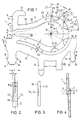
- the solid lines in FIG. 1 show the contact element in its open position, in which the contact lugs 7 are at a distance a from one another and the contact element 1 is spanned.
- the dash-dotted lines in FIG. 1 show the contact element 1 in its starting position, in which the contact lugs 7 abut one another and are biased towards one another due to an internal stress of the contact element 1.
- Known film connectors consist of a two-part plastic housing, one housing part of which can be a housing cover. In the interior of the housing, parallel to its side walls, chamber walls are arranged at a distance from one another net, so that narrow chambers are formed, in each of which a contact element 1 with its mounting parts 8, 9 and with its legs is received.
- the arrangement and mounting of the contact elements 1 in the film connector can be carried out in accordance with the arrangement and configuration which can be found in DE-OS 33 36 799, so that the upper leg 3 with its contact lug 7 is pivoted by pivoting movements of the cover part about its hinge axis to open the contact element 1. or can be bent out.
- the driving connection is formed by the mounting parts 8.9.
- the upper holding part 8 arranged on the leg 3 is shaped like a hook with an approximately vertical hook part 11 and a recessed approximately horizontal hook part 12, the latter being intended for the overlapping of an abutment on the cover part. To avoid repetition, reference is made in full to the description in DE-OS 33 36 799.
- the holding part 9 consists of a bridge web 13 which extends in the plane E of the contact element 1 under the lower leg 4 and which follows the shape of the leg 4 and the web 2 at its upper edge at a preferably uniform distance b, as a result of which a correspondingly concave Form of the bridge web 13 results.
- the bridge web 13 extends laterally in one piece from a main retaining web 14, which extends downward from the free end 6 of the leg 4 and is arrow-shaped at its downward end with two narrow-sided locking lugs 15 and starting bevels 16 starting from these.
- an auxiliary holding web 17 extends downward, which is also arrow-shaped at its free, downward-facing end with narrow-side latching lugs 18 and starting bevels 19 extending from these.
- two protrude from it one in the plane E of the contact elements 1 extending spacing c having mounting lugs 21, 22 downwards, of which at least one mounting lug can be extended and form a soldering leg.
- the internal stress of the contact element 1 already mentioned is generated by embossing the surface 20 of the bracket 23 consisting of the web 2 and the legs 3, 4 progressively towards the outer edge.
- the embossed outer edge zone of the bracket 23 is stretched by material deformation, which results in the “C” shape “going together”.
- the embossing can take place in the area of one and / or both legs 3, 4 and / or in the area of the web 2. If only one leg 3, 4 is embossed, there is an asymmetrical curvature or bending of the embossed leg 3, 4 because the other leg 3, not embossed remains unchanged.
- embossing both legs 3, 4 or embossing in the area of the web 2 and in particular in its apex area leads to a symmetrical change in shape of the bracket 23.
- embossments 24 to 27 are provided, which are distributed approximately uniformly over the curved length of the web 2.
- the two outer embossments 24, 27 adjoin the vertical transverse plane E1 through the base points of the legs 3, 4, the embossments of approximately the same size each extending over an angular range w of approximately 30 °, so that between the embossments 24 to 27 each gives an angular range wl of approximately 20 °.
- an embossing is designated, which can be arranged in the outer edge region of the lower leg 4 as a previously described embodiment variant.
- the embossing surface 31 is rounded in a concave manner, namely around an essentially radially extending axis, so that it is rounded at the embossing points Indentations in the form of troughs which extend transversely to the web 2 or radially.
- the embossing surfaces 31 are inclined outwards, ie, they enclose an acute angle w2 of preferably approximately 12 ° with the surface 20 or broad side 32 of the bracket 23 or web 2 containing them.
- a progressive embossing in the area of the outer edge 33 can be achieved by means of an embossing surface with flanks 29, 30 diverging outwards.
- An inclined and preferably rounded or curved embossing surface 31 also leads to such a shape, which results in a triangular shape of the embossing surface, from which two corners of the triangle lie on the outer edge 33 of the bracket 23, while the third corner to the center of curvature M of the web 2 indicates.
- the embossments 24 to 28 each extend over approximately two-thirds of the preferably approximately constant width B of the bracket 23. This dimension of extent is designated by the width e of the embossments or embossing surfaces 31.
- the maximum depth t of the embossments 24 to 28 is approximately one third of the thickness d of the web 2.
- the center lines of the embossing surfaces 31, designated 34 each close an equally large angle w3 of about 50 °. This embossing at an angle has proven to be particularly advantageous.
- the embossments 24 to 27 are preferably not carried out simultaneously but in succession. With a simultaneous embossing of several embossments 24 to 27, there is a risk that, depending on the attachment of the contact element 1, the desired tensions in the bracket 23 cancel each other out during embossing. Embossing in succession is therefore more advantageous.
- the embossments 24 to 27 are embossed one after the other in the sequence of the row shown with the embossing sequence 24-25-26-27 or 27-26-25-24.
- the embossing takes place after the contact element 1 has been punched out of the sheet metal, the solid lines in FIG. 1 not only showing the open shape of the contact element 1 but also its shape can represent punched form.
- the two contact lugs 7 are preferably in contact with one another, pressing against one another with a certain pretension, as is indicated in FIG. 1.
- the embossing is preferably carried out in a position shown in FIG. 4, in which the free ends 5, 6 of the bracket 23 are bent so far transversely to its plane E that they can be moved past one another during a movement parallel to the plane E.
- the legs 3, 4 or contact lugs 7 are moved toward one another, the contact lugs 7 overlapping one another and remaining in a specific overlapping position, which is predetermined by the strength of the embossing.
- the free ends 5, 6 are pulled apart a little and brought into the plane E, thereby generating the pretension with which they lie against one another in the plane E.
Abstract
Description
Die Erfindung bezieht sich auf ein Verfahren und ein Kontaktelement nach dem Oberbegriff des Anspruchs 1 bzw. 10.10. The invention relates to a method and a contact element according to the preamble of
Bei einem solchen Kontaktelement ist zum Zusammenpressen der Folie eine Eigenspannung in der C-förmigen Feder erforderlich, die die freien Enden der Feder mit ihren einander gegenüberliegenden Kontaktflächen gegeneinander beaufschlagt, um eine gewünschte Vorspannung zu erzeugen.With such a contact element, compressing the film requires an internal stress in the C-shaped spring, which presses the free ends of the spring against one another with their opposing contact surfaces in order to generate a desired prestress.
Bei einem aus der DE-OS 36 33 799 entnehmbaren Verfahren, ein Kontaktelement mit einer solchen Vorspannung zu versehen, werden die Schenkel der Feder nach dem Stanzen überbogen. Ein Zusammendrücken der Feder durch parallel zu ihrer Ebene gerichteten Druck auf die Schenkel ist schwierig sowie zeitaufwendig, und es läßt sich das Überbiegen auch schwer beherrschen, so daß sich nach dem Überbiegen von Kontaktelement zu Kontaktelement ungleiche Vorspannungen ergeben oder die Schenkel verhältnismäßig leicht zu weit überbogen werden können, wodurch das Kontaktelement unbrauchbar wird. Außerdem läßt sich das Kontaktelement beim Überbiegen nur durch aufwendige Stützmaßnahmen halten, wodurch schwierige Herstellungsmaßnahmen vorgegeben sind.In a method which can be found in DE-OS 36 33 799 to provide such a pretension for a contact element, the legs of the spring are bent over after stamping. Compression of the spring by parallel pressure on the legs is difficult and time-consuming, and it is difficult to master the overbending, so that after bending over from contact element to contact element there are uneven prestresses or the legs bend relatively easily too far can be, making the contact element unusable. In addition, the contact element can only be held by complex support measures during overbending, as a result of which difficult manufacturing measures are specified.
Die vorgenannten Schwierigkeiten ergeben sich auch aus der kleinen Baugröße, die das Kontaktelement der vorliegenden Art aufweisen kann.The aforementioned difficulties also result from the small size that the contact element of the present type can have.
Der Erfindung liegt die Aufgabe zugrunde, die Erzeugung der Vorspannung im Kontaktelement zu vereinfachen.The invention has for its object to simplify the generation of the bias in the contact element.
Diese Aufgabe wird durch die kennzeichnenden Merkmale der Ansprüche l bzw. 10 gelöst.This object is solved by the characterizing features of
Beim erfindungsgemäßen Verfahren werden die Schenkel der Feder durch das erfindungsgemäße Prägen aufeinanderzu vorgespannt. Das Prägen stellt eine Maßnahme dar, die einfach durchzuzführen ist, wobei beim Prägen das Kontaktelement einfach gehalten werden kann, da es mit einer Fläche an oder auf einem Prägewiderlager liegen kann. Außerdem läßt sich durch Prägen eine gewünschte Toleranz der Vorspannung besser einhalten und leichter beherrschen bzw. die angestrebte Formveränderung leichter und präziser erreichen und zwar durch die Stärke der Prägung.In the method according to the invention, the legs of the spring are biased towards one another by the embossing according to the invention. The embossing is a measure that is easy to carry out, wherein the contact element can be kept simple during the embossing, since it can lie on or on an embossing abutment with a surface. In addition, a desired tolerance of the pretension can be better maintained and mastered more easily by embossing, or the desired shape change can be achieved more easily and precisely, namely by the strength of the embossing.
Vorteilhafte Weiterbildungen des erfindungsgemäßen Verfahrens und des erfindungsgemäßen Kontaktelements, die das erfindungsgemäße Verfahren und die Bauweise vereinfachen und eine kostengünstige Herstellung und auch eine bessere Beherrschung der angetrebten Toleranz ermöglichen, sind in den Unteransprüchen beschrieben.Advantageous developments of the method according to the invention and of the contact element according to the invention, which simplify the method and the construction according to the invention and enable inexpensive production and also better control of the desired tolerance, are described in the subclaims.
Nachfolgend wird die Erfindung anhand eines in einer Zeichnung dargstellten bevorzugten Ausführungsbeispiels näher erläutert. Es zeigt
- Fig. 1 ein erfindungsgemäß hergestelltes und ausgebildetes Kontaktelement für einen Folienverbinder für gedruckte Schaltungen in stark vergrößerter Seitenansicht;
- Fig. 2 den Schnitt II-II in Fig. 1;
- Fig. 3 eine Teil-Seitenansicht des Kontaktelements in Blickrichtung des Pfeils von rechts;
- Fig. 4 das Kontaktelement in der Seitenansicht von links in einer besonderen Form-Stellung.
- 1 shows a contact element for a film connector for printed circuits manufactured and designed according to the invention in a greatly enlarged side view;
- Figure 2 shows the section II-II in Fig. 1.
- Figure 3 is a partial side view of the contact element in the direction of the arrow from the right.
- Fig. 4 shows the contact element in a side view from the left in a special shape position.
Das Kontaktelement 1 wird durch eine C-förmige Feder gebildet und besteht aus einem Blechstanzteil, wobei das Blech sich in der Ebene der C-Form erstreckt. Das Kontaktelement 1 weist keine Abbiegung aus dieser Blechebene auf. Es handelt sich um eine sogenannte Flächenformfeder.The
Die wesentlichen Teile des Kontaktelements 1 bzw. der Feder sind ein halbkreisbogenförmig gekrümmter Steg 2, sich an dessen freien Enden anschließende Schenkel 3,4, an deren freien Enden 5,6 Kontaktnasen 7 auf den einander zugewandten Seiten bzw. Innenseiten und Halterungsteile 8,9 auf den einander abgewandten Seiten bzw. Außenseiten angeordnet sind. Die Schenkel 3,4 erstrecken sich zu ihren freien Enden 5,6 hin konvergent zueinander, wobei sie etwas konkav gekrümmt sind, so daß der Steg 2 mit den Schenkeln 3,4 eine Tropfenform darstellen. Die Kontaktnasen 7 sind durch gerundete Vorsprünge gebildet.The essential parts of the
Die in Fig. 1 durchgezogenen Linien zeigen das Kontaktelement in seiner geöffneten Stellung, in der die Kontaktnasen 7 einen Abstand a voneinander aufweisen und das Kontaktelement 1 aufgespannt ist. Die in Fig. l strichpunktierten Linien zeigen das Kontaktelement 1 in seiner Ausgangsstellung, in der die Kontaktnasen 7 aneinanderliegen und aufgrund einer Eigenspannung des Kontaktelements 1 in Richtung aufeinanderzu vorgespannt sind.The solid lines in FIG. 1 show the contact element in its open position, in which the
Bekannte Folienverbinder bestehen aus einem zweiteiligen Kunststoffgehäuse, dessen eines Gehäuseteil ein Gehäusedeckel sein kann. Im Innenraum des Gehäuses sind parallel zu seinen Seitenwandungen auf Abstand voneinander Kammerwandungen angeord net, so daß schmale Kammern gebildet werden, in denen jeweils ein Kontaktelement 1 mit seinen Halterungsteilen 8,9 und mit seinen Schenkeln aufgenommen ist. Die Anordnung und Halterung der Kontaktelemente 1 im Folienverbinder kann gemäß der aus der DE-OS 33 36 799 entnehmbaren Anordnung und Ausgestaltung erfolgen, so daß der obere Schenkel 3 mit seiner Kontaktnase 7 durch Schwenkbewegungen des Deckelteils um seine Gelenkachse zum Öffnen des Kontaktelements 1 hoch- bzw. ausgebogen werden kann. Dieses Ausbiegen erfolgt im elastischen Biegebereich des Kontaktelements 1, so daß nach Freigabe des Deckelteils der Schenkel 3 in seine Ausgangsstellung zurückbiegt und dabei das Deckelteil zurückdrehen kann. Die Mitnahmeverbindung wird jeweils durch die Halterungsteile 8,9 gebildet. Das obere, am Schenkel 3 angeordnete Halterungsteil 8 ist hakenförmig geformt mit einem etwa vertikalen Hakenteil 11 und einem zurückspringenden etwa horizontalen Hakenteil 12, wobei letzteres für das Übergreifen eines Widerlagers am Deckelteil bestimmt ist. Zwecks Vermeidung von Wiederholungen wird auf die Beschreibung in der DE-OS 33 36 799 in vollem Umfang Bezug genommen.Known film connectors consist of a two-part plastic housing, one housing part of which can be a housing cover. In the interior of the housing, parallel to its side walls, chamber walls are arranged at a distance from one another net, so that narrow chambers are formed, in each of which a
Das Halterungsteil 9 besteht aus einem sich in der Ebene E des Kontaktelements l unter dem unteren Schenkel 4 erstreckenden Brückensteg 13, der an seiner Oberkante in einem vorzugsweise gleichmäßigen Abstand b der Form des des Schenkels 4 und des Stegs 2 folgt, wodurch sich eine entsprechend konkave Form des Brückenstegs 13 ergibt. Der Brückensteg 13 geht seitlich von einem Haupthaltesteg 14 einteilig aus, der sich vom freien Ende 6 des Schenkels 4 nach unten erstreckt und an seinem nach unten gerichteten Ende mit zwei schmalseitigen Verrastungsnasen 15 und von diesen ausgehenden Anlaufschrägen 16 pfeilförmig ausgebildet ist. Am dem Haupthaltesteg 14 abgewandten Ende des Brückenstegs 13 erstreckt sich ein Hilfshaltesteg 17 nach unten, der an seinem freien, nach unten weisenden Ende mit schmalseitigen Verrastungsnasen 18 und von diesen ausgehenden Anlaufschrägen 19 ebenfalls pfeilförmig ausgebildet ist. Etwa in der Mitte des Brückenstegs 13 ragen von diesem zwei, einen sich in der Ebene E des Kontakt elements 1 erstreckenden Abstand c aufweisende Halterungsansätze 21,22 nach unten, von denen wenigstens ein Halterunsansatz verlängert sein und ein Lötbein bilden kann. Im in das Gehäuse des Folienverbinders eingebauten Zustand fassen der Haupthalterungssteg 14 und der Hilfshalterungssteg 17 sowie die Halterungsansätze 21,22 in Einsteckschlitze jeweils in entsprechender Form und Größe ein, wobei die Verrastungsnasen 15,18 verrasten.The holding part 9 consists of a
Die schon erwähnte Eigenspannung des Kontaktelements 1 wird durch ein zur äußeren Kante progressives Prägen der Fläche 20 des aus dem Steg 2 und den Schenkeln 3,4 bestehenden Bügels 23 erzeugt. Hierdurch wird die geprägte äußere Randzone des Bügels 23 durch Materialverformung gestreckt, was ein "Zusammengehen" der C-Form zur Folge hat. Das Prägen kann im Bereich eines und/oder beider Schenkel 3,4 und/oder im Bereich des Stegs 2 erfolgen. Wenn nur ein Schenkel 3,4 geprägt wird, ergibt sich eine unsymmetrische Krümmung bzw. Biegung des geprägten Schenkels 3,4, weil der andere nicht geprägte Schenkel 3,4 unverändert bleibt. Dagegen führt ein Prägen beider Schenkel 3,4 oder Prägen im Bereich des Stegs 2 und insbesondere in dessen Scheitelbereich zu einer symmetrischen Formveränderung des Bügels 23.The internal stress of the
Bei der vorliegenden Ausgestaltung sind vier Prägungen 24 bis 27 vorgesehen, die auf der gekrümmten Länge des Stegs 2 etwa gleichmäßig verteilt sind. Dabei grenzen die beiden äußeren Prägungen 24,27 an die durch die Fußpunkte der Schenkel 3,4 gehenden vertikalen Querebene El an, wobei die etwa gleich großen Prägungen sich jeweils über einen Winkelbereich w von etwa 30°, erstrecken, so daß sich zwischen den Prägungen 24 bis 27 jeweils ein Winkelbereich wl von etwa 20° ergibt. Mit 28 ist eine Prägung bezeichnet, die im äußeren Randbereich des unteren Schenkels 4 als vorbeschriebene Ausgestaltungsvariante angeordnet sein kann.In the present embodiment, four embossments 24 to 27 are provided, which are distributed approximately uniformly over the curved length of the
Wie die Fig. 2 und 3 deutlich zeigen, ist die Prägefläche 31 jeweils konkav gerundet und zwar um eine im wesentlichen radial verlaufende Achse, so daß sich an den Prägestellen gerundete Vertiefungen in Form von Mulden ergeben, die sich quer zum Steg 2 bzw. radial erstrecken. Dabei sind die Prägeflächen 31 nach außen geneigt, d.h., sie schließen mit der sie enthaltenden Fläche 20 bzw. Breitseite 32 des Bügels 23 bzw. Stegs 2 einen spitzen Winkel w2 von vorzugsweise etwa 12° ein.As clearly shown in FIGS. 2 and 3, the embossing surface 31 is rounded in a concave manner, namely around an essentially radially extending axis, so that it is rounded at the embossing points Indentations in the form of troughs which extend transversely to the
Eine im Bereich der äußeren Kante 33 progressive Prägung läßt sich durch eine Prägefläche mit nach außen divergierenden Flanken 29,30 erreichen. Zu einer solchen Form führt auch eine geneigte und vorzugsweise gerundete bzw. gekrümmte Prägefläche 31, woraus sich eine dreieckige Form der Prägefläche ergibt, von der zwei Ecken des Dreiecks an der Außenkante 33 des Bügels 23 liegen, während die dritte Ecke zum Krümmungsmittelpunkt M des Stegs 2 hin weist. Die Prägungen 24 bis 28 erstrecken sich jeweils etwa über Zweidrittel der vorzugsweise etwa konstanten Breite B des Bügels 23. Dieses Erstreckungsmaß wird mit Breite e der Prägungen bzw. Prägeflächen 31 bezeichnet. Die maximale Tiefe t der Prägungen 24 bis 28 beträgt etwa ein Drittel der Dicke d des Stegs 2. Bei der vorbeschriebenen Anordnung der Prägungen 24 bis 27 im Bereich des gekrümmten Stegs 2 schließen die mit 34 bezeichneten Mittellinien der Prägeflächen 31 jeweils einen gleich großen Winkel w3 von etwa 50° ein. Dieses Prägen unter einem Winkel hat sich als besonders vorteilhaft erwiesen.A progressive embossing in the area of the
Die Prägungen 24 bis 27 werden vorzugsweise nicht simultan sondern nacheinander durchgeführt. Bei einer simultanen Prägung mehrerer Prägungen 24 bis 27 besteht die Gefahr, daß je nach Befestigung des Kontaktelements 1 beim Prägen sich die gewünschten Spannungen im Bügel 23 aufheben. Ein Prägen nacheinander ist deshalb vorteilhafter. Vorzugsweise werden die Prägungen 24 bis 27 in der Folge der dargestellten Reihe nacheinander geprägt mit der Prägefolge 24-25-26-27 oder 27-26-25-24.The embossments 24 to 27 are preferably not carried out simultaneously but in succession. With a simultaneous embossing of several embossments 24 to 27, there is a risk that, depending on the attachment of the
Das Prägen erfolgt nach dem Stanzen des Kontaktelements 1 aus dem Blech, wobei die in Fig. 1 durchgezogenen Linien nicht nur die geöffnete Form des Kontaktelements 1 sondern auch dessen gestanzte Form darstellen können. Nach dem Prägen stehen die beiden Kontaktnasen 7 vorzugsweise miteinander in Berührung, wobei sie mit einer bestimmten Vorspannung gegeneinander drücken, wie es in Fig. 1 augdeutet ist.The embossing takes place after the
Das Prägen erfolgt vorzugsweise in einer in Fig. 4 dargestellten Position, in der die freien Enden 5,6 des Bügels 23 quer zu dessen Ebene E soweit abgebogen sind, daß sie bei einer Bewegung parallel zur Ebene E aneinander vorbei bewegt werden können. Während des Prägens werden die Schenkel 3,4 bzw. Kontaktnasen 7 aufeinanderzu bewegt, wobei die Kontaktnasen 7 einander überlappen und in einer bestimmten einander überlappenden Stellung verbleiben, die durch die Stärke der Prägung vorgegeben ist. Zur Inbetriebsetzung des Kontaktelements 1 bzw. bei dessen Montage im Folienverbinder werden die freien Enden 5,6 etwas auseinandergezogen und in die Ebene E gebracht, wodurch die Vorspannung erzeugt wird, mit der sie in der Ebene E aneinander liegen.The embossing is preferably carried out in a position shown in FIG. 4, in which the free ends 5, 6 of the
Claims (23)
dadurch gekennzeichnet,
daß zum Einbiegen das Kontaktelement (1) die Fläche (20) der Feder (23) nach dem Stanzen so geprägt wird, daß im Randbereich der Außenkante (33) mehr Material gestreckt wird als im Randbereich der Innenkante.1. A method for producing a contact element in the form of a C-shaped spring with contact tabs lying against one another or at a short distance from one another for a film connector, in which the spring is punched out of a flat material, in particular sheet metal, which extends in the plane of the spring, and then the contact element is bent in,
characterized,
that for bending the contact element (1) the surface (20) of the spring (23) is stamped so that more material is stretched in the edge region of the outer edge (33) than in the edge region of the inner edge.
dadurch gekennzeichnet,
daß der äußere Randbereich der Fläche (20) der Feder (23) geprägt wird.2. The method according to claim 1,
characterized,
that the outer edge region of the surface (20) of the spring (23) is embossed.
dadurch gekennzeichnet,
daß die Fläche (20) im Bereich eines oder beider Schenkel (3,4) und/oder des Stegs (2) der Feder (23) geprägt wird.3. The method according to claim 1 or 2,
characterized,
that the surface (20) in the region of one or both legs (3, 4) and / or the web (2) of the spring (23) is embossed.
dadurch gekennzeichnet,
daß zum Prägen ein Prägestempel mit einer zur Außenkante (33) der Fläche (20) hin geneigten und vorzugsweise in Längsrichtung der Feder konvex gekrümmten Prägefläche (31) gegen die Fläche (20) der Feder (23) gedrückt wird.4. The method according to claim one or more of claims 1 to 3,
characterized,
that an embossing stamp is pressed against the surface (20) of the spring (23) with an embossing surface (31) inclined towards the outer edge (33) of the surface (20) and preferably convexly curved in the longitudinal direction of the spring.
dadurch gekennzeichnet,
daß mehrere Prägungen (24 bis 27) vorzugsweise jeweils nacheinander geprägt werden.5. The method according to one or more of claims 1 to 4,
characterized,
that several embossments (24 to 27) are preferably embossed one after the other.
dadurch gekennzeichnet
, daß die Prägungen in der sich längs der Feder (23) gerichteten Reihenfolge (24-25-26-27 oder 27-26-25-24) geprägt werden6. The method according to claim 5,
characterized
that the embossments are embossed in the order (24-25-26-27 or 27-26-25-24) directed along the spring (23)
dadurch gekennzeichnet,
daß zuerst wenigstens eine, vorzugsweise zwei Grundprägungen und dann wenigstens eine, vorzugsweise zwei Nachprägungen zur Feinabstimmung geprägt werden.7. The method according to claim 4 or 5,
characterized,
that first at least one, preferably two basic embossings and then at least one, preferably two post-embossings are coined for fine tuning.
dadurch gekennzeichnet,
daß die freien Enden (5,6) der Feder (23) vor dem Prägen quer zur Ebene (E) der Feder (23) soweit voneinander gebogen werden, daß sie bezüglich der Ebene (E) der Feder (23) nebeneinander liegen, und daß dann geprägt wird.8. The method according to at least one of claims 1 to 7,
characterized,
that the free ends (5, 6) of the spring (23) are bent so far from each other before embossing transversely to the plane (E) of the spring (23) that they lie next to one another with respect to the plane (E) of the spring (23), and that is then shaped.
dadurch gekennzeichnet,
daß nach dem Prägen gegebenenfalls bei der Montage des Kontaktelements (1) in einem Folienverbinder, die freien Enden (5,6) der Feder (23) auseinandergezogen und in die Ebene (E) der Feder (23) zurückversetzt werden.9. The method according to claim 8,
characterized,
that after embossing, if necessary, during assembly of the Contact element (1) in a film connector, the free ends (5,6) of the spring (23) are pulled apart and set back into the plane (E) of the spring (23).
dadurch gekennzeichnet,
daß auf wenigstens einer Fläche (20) der Feder (23) wenigstens eine Prägung (24 bis 27) vorgesehen ist, die die Feder (23) im Randbereich ihrer Außenkante (33) mehr streckt als im Bereich ihrer Innenkante.10. Contact element for a film connector, consisting of a C-shaped spring made of flat material extending in the plane of the spring, in particular sheet metal, which has contact lugs facing one another at the free ends of its legs, which contact one another in the initial position of the spring or a small one Distance from each other,
characterized,
that on at least one surface (20) of the spring (23) there is at least one embossment (24 to 27) which stretches the spring (23) more in the edge region of its outer edge (33) than in the region of its inner edge.
dadurch gekennzeichnet,
daß die Prägung (24 bis 27) im äußeren Randbereich der Feder (23) angeordnet ist.11. Contact element according to claim 10,
characterized,
that the embossing (24 to 27) is arranged in the outer edge region of the spring (23).
dadurch gekennzeichnet,
daß die Prägung (24 bis 27) von der Außenkante (33) der Feder (23) ausgehend sich über einen Teil der Breite (B) der Feder (23) erstreckt.12. Contact element according to claim 10 or 11,
characterized,
that the embossing (24 to 27) from the outer edge (33) of the spring (23) extends over part of the width (B) of the spring (23).
dadurch gekennzeichnet,
daß die sich quer zur Längsrichtung der Feder (23) erstrekkende Breite (e) der Prägung (24 bis 27) etwa Zweidrittel der Breite (B) der Feder (23) entspricht.13. Contact element according to claim 12,
characterized,
that the width (e) of the embossing (24 to 27) extending transversely to the longitudinal direction of the spring (23) corresponds to approximately two-thirds of the width (B) of the spring (23).
dadurch gekennzeichnet,
daß die Prägefläche (31) der Prägung (24 bis 27) zur Außenkante (33) der Feder (23) geneigt ist und mit der Ebene (E) oder Fläche (20) der Feder (23) einen spitzen Winkel (w1) von vorzugsweise etwa 12° einschließt.14. Contact element according to at least one of claims 10 to 13,
characterized,
that the embossing surface (31) of the embossing (24 to 27) is inclined to the outer edge (33) of the spring (23) and with the plane (E) or surface (20) of the spring (23) an acute angle (w1) of preferably includes about 12 °.
dadurch gekennzeichnet,
daß die Flanken (29,30) der Prägefläche (31) der Prägung zur Außenkante (33) der Feder (23) hin divergieren und einen Winkel (w4) von vorzugsweise etwa 90° einschließen.15. Contact element according to one or more of claims 10 to 14,
characterized,
that the flanks (29, 30) of the embossing surface (31) of the embossing diverge towards the outer edge (33) of the spring (23) and enclose an angle (w4) of preferably approximately 90 °.
dadurch gekennzeichnet,
daß die Prägefläche (31) der Prägung von dreieckiger Form ist.16. Contact element according to claim 15,
characterized,
that the embossing surface (31) of the embossing is triangular in shape.
dadurch gekennzeichnet,
daß die Prägefläche (31) der Prägung (24 bis 27) im Sinne einer zylinderabschnittförmigen Fläche um eine quer zur Feder (23) verlaufende Achse konkav gerundet ist.17. Contact element according to one or more of claims 10 to 16,
characterized,
that the embossing surface (31) of the embossing (24 to 27) is concavely rounded in the sense of a cylindrical section-shaped surface about an axis running transversely to the spring (23).
dadurch gekennzeichnet,
daß die Prägung (24 bis 27) sich im Bereich des Stegs (2) befindet und vorzugsweise der Steg (2) der Feder(23) etwa halbkreisförmig gerundet ist.18. Contact spring according to one or more of claims 10 to 17,
characterized,
that the embossing (24 to 27) is in the region of the web (2) and preferably the web (2) of the spring (23) is rounded approximately semi-circular.
dadurch gekennzeichnet,
daß mehrere, vorzugsweise vier Prägungen (24 bis 27) in gleichen oder unterschiedlichen Abständen voneinander in einer sich längs der Feder (23) erstreckenden Reihe vorgesehen sind.19. Contact element according to one or more of claims 1 to 18,
characterized,
that several, preferably four embossings (24 to 27) at the same or different distances from each other in a row extending along the spring (23) is provided.
dadurch gekennzeichnet,
daß die erste und letzte Prägung (24,27) an der durch die Fußpunkte der Schenkel (3,4) gehenden Querebene (E1) angrenzen.20. Contact element according to claim 19,
characterized,
that the first and last embossing (24, 27) adjoin the transverse plane (E1) passing through the base points of the legs (3, 4).
dadurch gekennzeichnet,
daß die Prägung (24 bis 27) sich jeweils über einen Winkelbereich (w) von etwa 30° erstreckt.21. Contact element according to claim 19 or 20,
characterized,
that the embossing (24 to 27) extends over an angular range (w) of approximately 30 °.
dadurch gekennzeichnet,
daß die Tiefe (t) der Prägung (24,27) etwa einem Drittel der Dicke (d) der Feder (23) entspricht.22. Contact element according to one or more of claims 10 to 21,
characterized,
that the depth (t) of the embossing (24, 27) corresponds to approximately one third of the thickness (d) of the spring (23).
dadurch gekennzeichnet,
daß beide Flächen (26) der Feder (23) geprägt sind.23. Contact element according to one or more of claims 10 to 22,
characterized,
that both surfaces (26) of the spring (23) are embossed.
Applications Claiming Priority (2)
| Application Number | Priority Date | Filing Date | Title |
|---|---|---|---|
| DE3925598 | 1989-08-02 | ||
| DE3925598A DE3925598A1 (en) | 1989-08-02 | 1989-08-02 | METHOD FOR PRODUCING A CONTACT ELEMENT FOR A FILM CONNECTOR AND CONTACT ELEMENT FOR SUCH A FILM CONNECTOR |
Publications (2)
| Publication Number | Publication Date |
|---|---|
| EP0411393A2 true EP0411393A2 (en) | 1991-02-06 |
| EP0411393A3 EP0411393A3 (en) | 1991-05-15 |
Family
ID=6386372
Family Applications (1)
| Application Number | Title | Priority Date | Filing Date |
|---|---|---|---|
| EP19900113749 Withdrawn EP0411393A3 (en) | 1989-08-02 | 1990-07-18 | Method of manufacturing a contact element for a sheet connector and contact element for this sheet connector |
Country Status (5)
| Country | Link |
|---|---|
| EP (1) | EP0411393A3 (en) |
| JP (1) | JPH0371941A (en) |
| DD (1) | DD296866A5 (en) |
| DE (1) | DE3925598A1 (en) |
| ZA (1) | ZA905792B (en) |
Cited By (3)
| Publication number | Priority date | Publication date | Assignee | Title |
|---|---|---|---|---|
| WO1997032371A1 (en) * | 1996-02-26 | 1997-09-04 | Gianfranco Natali | Elastic contact tongue and process for its production from a metal plate |
| CN101577382B (en) * | 2008-05-10 | 2011-04-13 | 富士康(昆山)电脑接插件有限公司 | Electric connector terminal |
| CN102699192A (en) * | 2012-05-29 | 2012-10-03 | 苏州旭创精密模具有限公司 | Contact spring piece die |
Families Citing this family (1)
| Publication number | Priority date | Publication date | Assignee | Title |
|---|---|---|---|---|
| DE10352069B9 (en) * | 2002-11-22 | 2013-05-29 | Tyco Electronics Amp Gmbh | Plug contact arrangement |
Citations (3)
| Publication number | Priority date | Publication date | Assignee | Title |
|---|---|---|---|---|
| EP0068697A1 (en) * | 1981-06-25 | 1983-01-05 | AMP INCORPORATED (a New Jersey corporation) | Method of manufacturing an electrical contact |
| US4638559A (en) * | 1984-10-30 | 1987-01-27 | At&T Technologies, Inc. | Methods of and apparatus for making slotted beam contact elements |
| EP0263296A2 (en) * | 1986-10-03 | 1988-04-13 | Grote & Hartmann GmbH & Co. KG | Foil connector for printed circuit |
-
1989
- 1989-08-02 DE DE3925598A patent/DE3925598A1/en not_active Withdrawn
-
1990
- 1990-07-18 EP EP19900113749 patent/EP0411393A3/en not_active Withdrawn
- 1990-07-24 ZA ZA905792A patent/ZA905792B/en unknown
- 1990-08-01 DD DD90343192A patent/DD296866A5/en unknown
- 1990-08-02 JP JP2206681A patent/JPH0371941A/en active Pending
Patent Citations (3)
| Publication number | Priority date | Publication date | Assignee | Title |
|---|---|---|---|---|
| EP0068697A1 (en) * | 1981-06-25 | 1983-01-05 | AMP INCORPORATED (a New Jersey corporation) | Method of manufacturing an electrical contact |
| US4638559A (en) * | 1984-10-30 | 1987-01-27 | At&T Technologies, Inc. | Methods of and apparatus for making slotted beam contact elements |
| EP0263296A2 (en) * | 1986-10-03 | 1988-04-13 | Grote & Hartmann GmbH & Co. KG | Foil connector for printed circuit |
Cited By (3)
| Publication number | Priority date | Publication date | Assignee | Title |
|---|---|---|---|---|
| WO1997032371A1 (en) * | 1996-02-26 | 1997-09-04 | Gianfranco Natali | Elastic contact tongue and process for its production from a metal plate |
| CN101577382B (en) * | 2008-05-10 | 2011-04-13 | 富士康(昆山)电脑接插件有限公司 | Electric connector terminal |
| CN102699192A (en) * | 2012-05-29 | 2012-10-03 | 苏州旭创精密模具有限公司 | Contact spring piece die |
Also Published As
| Publication number | Publication date |
|---|---|
| DE3925598A1 (en) | 1991-02-07 |
| DD296866A5 (en) | 1991-12-19 |
| ZA905792B (en) | 1991-04-24 |
| JPH0371941A (en) | 1991-03-27 |
| EP0411393A3 (en) | 1991-05-15 |
Similar Documents
| Publication | Publication Date | Title |
|---|---|---|
| DE19601647C2 (en) | Sealing plug | |
| EP0703021B1 (en) | Method of manufacturing a two-part cage nut | |
| DE4222869A1 (en) | ELECTROMAGNETIC SHIELDING SEAL | |
| EP0059462A2 (en) | Pressurized connection pin | |
| DE2641672A1 (en) | METHOD OF MANUFACTURING A PROFILE STRIP FOR SEALING, GUIDING OR COVERING | |
| DE2342443C3 (en) | Electrical plug connection | |
| DE2035947A1 (en) | Device for connecting the pipe plates and water tank of coolers and the like | |
| EP0411393A2 (en) | Method of manufacturing a contact element for a sheet connector and contact element for this sheet connector | |
| EP0054177B1 (en) | Connecting device for two construction parts | |
| DE4039032C1 (en) | Filter for liq. fuel for tank of motor vehicle - comprising filter mesh on all sides with flexible frame so filter can be bent for inserting into tank, and pipe connection | |
| DE2750110A1 (en) | Clip=on flange for rectangular box section duct - has hollow L=section with bar forming channel with double thickness walls housing duct edge | |
| LU101643B1 (en) | Plug contact element, direct plug connector, method for producing a plug contact element and method for producing a direct plug connector | |
| DE3324737A1 (en) | Contact spring and a method for its production | |
| DE3323453A1 (en) | IMPROVEMENTS ON CONNECTING LADDERS FOR CONNECTING VEHICLE LIGHTS | |
| EP0121720B1 (en) | Electrical contact arrangement for connecting boxes together | |
| DE1953280A1 (en) | Disc springs and process for their manufacture | |
| DE3514025A1 (en) | Method for the floating retention of threaded workpieces | |
| DE102020006771B4 (en) | Housing, namely a spring chamber for a medical device, and a blank for producing such a spring chamber | |
| LU501814B1 (en) | Method for producing a stamped grid part and base clamp comprising stamped grid part | |
| DE2810828C2 (en) | Compact double flat spring | |
| DE3220456A1 (en) | Lamp carrier | |
| DE19817080C2 (en) | Mounting rail | |
| DE202005006411U1 (en) | Flat metal gasket with holding tabs for sealing joint has outer edge of main seal with projections | |
| DE2048900B2 (en) | METHOD OF MANUFACTURING A FORK CONTACT SPRING | |
| DE19501855C2 (en) | Method for producing a switch arrangement having a plurality of functionally independent electrical switches |
Legal Events
| Date | Code | Title | Description |
|---|---|---|---|
| PUAI | Public reference made under article 153(3) epc to a published international application that has entered the european phase |
Free format text: ORIGINAL CODE: 0009012 |
|
| AK | Designated contracting states |
Kind code of ref document: A2 Designated state(s): DE ES FR GB IT SE |
|
| PUAL | Search report despatched |
Free format text: ORIGINAL CODE: 0009013 |
|
| AK | Designated contracting states |
Kind code of ref document: A3 Designated state(s): DE ES FR GB IT SE |
|
| STAA | Information on the status of an ep patent application or granted ep patent |
Free format text: STATUS: THE APPLICATION HAS BEEN WITHDRAWN |
|
| 18W | Application withdrawn |
Withdrawal date: 19910605 |