EP0405725A2 - Method and apparatus for controlling motorgrader cross slope cut - Google Patents
Method and apparatus for controlling motorgrader cross slope cut Download PDFInfo
- Publication number
- EP0405725A2 EP0405725A2 EP90304714A EP90304714A EP0405725A2 EP 0405725 A2 EP0405725 A2 EP 0405725A2 EP 90304714 A EP90304714 A EP 90304714A EP 90304714 A EP90304714 A EP 90304714A EP 0405725 A2 EP0405725 A2 EP 0405725A2
- Authority
- EP
- European Patent Office
- Prior art keywords
- angle
- blade
- slope
- motorgrader
- relative
- Prior art date
- Legal status (The legal status is an assumption and is not a legal conclusion. Google has not performed a legal analysis and makes no representation as to the accuracy of the status listed.)
- Withdrawn
Links
Images

Classifications
-
- E—FIXED CONSTRUCTIONS
- E02—HYDRAULIC ENGINEERING; FOUNDATIONS; SOIL SHIFTING
- E02F—DREDGING; SOIL-SHIFTING
- E02F9/00—Component parts of dredgers or soil-shifting machines, not restricted to one of the kinds covered by groups E02F3/00 - E02F7/00
- E02F9/20—Drives; Control devices
- E02F9/2025—Particular purposes of control systems not otherwise provided for
- E02F9/2037—Coordinating the movements of the implement and of the frame
-
- E—FIXED CONSTRUCTIONS
- E02—HYDRAULIC ENGINEERING; FOUNDATIONS; SOIL SHIFTING
- E02F—DREDGING; SOIL-SHIFTING
- E02F3/00—Dredgers; Soil-shifting machines
- E02F3/04—Dredgers; Soil-shifting machines mechanically-driven
- E02F3/76—Graders, bulldozers, or the like with scraper plates or ploughshare-like elements; Levelling scarifying devices
- E02F3/80—Component parts
- E02F3/84—Drives or control devices therefor, e.g. hydraulic drive systems
- E02F3/844—Drives or control devices therefor, e.g. hydraulic drive systems for positioning the blade, e.g. hydraulically
- E02F3/845—Drives or control devices therefor, e.g. hydraulic drive systems for positioning the blade, e.g. hydraulically using mechanical sensors to determine the blade position, e.g. inclinometers, gyroscopes, pendulums
-
- E—FIXED CONSTRUCTIONS
- E02—HYDRAULIC ENGINEERING; FOUNDATIONS; SOIL SHIFTING
- E02F—DREDGING; SOIL-SHIFTING
- E02F9/00—Component parts of dredgers or soil-shifting machines, not restricted to one of the kinds covered by groups E02F3/00 - E02F7/00
- E02F9/08—Superstructures; Supports for superstructures
- E02F9/0841—Articulated frame, i.e. having at least one pivot point between two travelling gear units
-
- Y—GENERAL TAGGING OF NEW TECHNOLOGICAL DEVELOPMENTS; GENERAL TAGGING OF CROSS-SECTIONAL TECHNOLOGIES SPANNING OVER SEVERAL SECTIONS OF THE IPC; TECHNICAL SUBJECTS COVERED BY FORMER USPC CROSS-REFERENCE ART COLLECTIONS [XRACs] AND DIGESTS
- Y10—TECHNICAL SUBJECTS COVERED BY FORMER USPC
- Y10S—TECHNICAL SUBJECTS COVERED BY FORMER USPC CROSS-REFERENCE ART COLLECTIONS [XRACs] AND DIGESTS
- Y10S37/00—Excavating
- Y10S37/907—Automatic leveling excavators
Definitions
- the present invention relates generally to a motorgrader having a two-part articulated frame defined by a rear drive unit and a front steering unit which can be rotated or pivoted relative to the drive unit and, more particularly, to an improved method and apparatus for controlling the cross slope angle cut by such a motorgrader while the motorgrader is being operated with the steering unit in a pivoted position relative to the drive unit.
- One such system permits a motorgrader operator to preset the slope of the blade and maintain that slope by servo valves or the like activated by a blade slope sensor.
- the blade slope sensor is mounted on the blade or a blade supporting structure. While these systems may be made to accurately reflect the blade slope relative to horizontal, they do not always reflect the true cross slope of the cut being made by the motorgrader, i. e. the slope normal to the direction of travel of the motorgrader. For example, errors occur when the blade is not positioned perpendicular to the direction of travel which is normally the case during operation when dirt is to be moved to one side or the other of the motorgrader.
- motorgraders have a two-part articulated frame defined by a rear drive unit and a front steering unit which can be rotated or pivoted relative to the drive unit. Oftentimes it is required or desireable to operate a motorgrader with the front steering unit articulated at an angle relative to the rear drive unit, for example to position the drive unit on firm ground.
- the operating position is referred to as a "crabbed" steering position due to the movement of the motorgrader in an indirect or diagonal manner as a crab moves.
- the disclosed control system is ineffective .
- apparatus for controlling the cross slope angle of a surface being worked by a motorgrader having a two-part articulated frame defined by a rear drive unit including rear drive wheels and a front steering unit which can be rotated relative to the drive unit and including front steering wheels.
- a blade is supported upon the steering unit for rotation about a generally vertical axis with the blade being mounted for adjustment of the elevations of its ends to define a blade slope angle relative to horizontal.
- the apparatus comprises input means for selecting a desired cross slope angle, first angle sensor means for sensing the angle of rotation of the blade relative to the steering unit, and second angle sensor means for sensing the angle of rotation of the steering unit relative to the drive unit.
- First slope sensor means sense the blade slope angle of the blade relative to horizontal and second slope sensor means sense the direction of travel slope angle of the motorgrader.
- Cross slope control means is connected to the input means, to the first and second angle sensor means, and to the first and second slope sensor means for controlling the blade slope angle to maintain the desired cross slope when the motorgrader is operated in a crabbed steering position.
- the second angle sensor means may be mounted at an articulation joint interconnecting the steering unit to the drive unit of the motorgrader or adjacent and coupled to the front steering wheels of the motorgrader, as preferred for a given application.
- the cross slope control means then controls the blade slope so that the sensed blade slope angle is substantially equal to the calculated blade slope angle to maintain the desired cross slope when the motorgrader is operated in a crabbed steering position.
- a method for controlling the cross slope angle of a surface being worked by a motorgrader having a two-part articulated frame defined by a rear drive unit including rear drive wheels and a front steering unit which can be rotated relative to the drive unit and including front steering wheels.
- a blade is supported upon the steering unit for rotation about a generally vertical axis with the blade being mounted for adjustment of the elevations of its ends to define a blade slope angle relative to horizontal.
- the method for controlling the cross slope angle of a surface being worked by the motorgrader comprises the steps of: selecting a desired cross slope angle; sensing the angle of rotation of the blade relative to the steering unit; sensing the angle of rotation of the steering unit relative to the drive unit; sensing the blade slope angle of the blade relative to horizontal; sensing the direction of travel slope of the motor grader; and controlling the blade slope angle as a function of the desired cross slope angle, the blade rotation angle, the steering unit rotation angle, and the motorgrader direction of travel slope angle to maintain the desired cross slope when the motorgrader is operated in a crabbed steering position.
- the step of sensing the angle of rotation of the steering unit relative to the drive unit may comprise the step of installing an angle sensor at an articulation joint interconnecting the steering unit to the drive unit or the step of installing an angle sensor adjacent and coupled to the front steering wheels, as preferred for a given application.
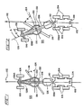
- Figs. 1 and 2 schematically illustrate a two-part articulated frame motorgrader 100 in plan view.
- the motorgrader 100 includes a rear drive unit 102 including rear drive wheels 104 and a front steering unit 106 including front steering wheels 108.
- the front steering unit 106 is connected to the rear drive unit 102 by a frame articulation joint 110 so that the steering unit 106 can be rotated relative to the drive unit 102 to assist the steering wheels 108 in steering the motorgrader 100 and to permit "crabbed" steering of the motorgrader 100 as shown in Fig. 2. While straight frame operation as shown in Fig.
- a blade 114 is supported upon the steering unit 106 by means of a draw bar/turntable arrangement commonly referred to as a "ring" or “circle” 116 so that the blade 114 can be rotated about a generally vertical axis collinear with the center of the circle 116.
- the control system of U. S. Patent No. 3,786,871, which is incorporated herein by reference, or an equivalent system is capable of maintaining a desired cross slope, i. e. the slope normal to the direction of travel of the motorgrader 100, for the cut being made by the motorgrader 100.
- a desired cross slope i. e. the slope normal to the direction of travel of the motorgrader 100
- a method and apparatus are provided to control the cross slope of the cut being made by the motorgrader 100 even when the motorgrader 100 is operated in a crabbed steering postion.
- the apparatus required for operation of the present invention includes input means comprising an input device 118, see Fig. 3, such as a keyboard or the like, for selecting a desired cross slope angle C.
- the input device 118 is typically mounted in the operator's cab (not shown) for the motorgrader 100.
- First angle sensor means comprising an angle sensor 120 senses the angle of rotation R of the blade 114 relative to the steering unit 106.
- the blade angle of rotation R is measured relative to a line 124 perpendicular to the axis 126 of the steering unit 106 so that a zero degree blade rotation angle corresponds to positioning the blade 114 perpendicular to the steering unit 106. Further, for proper operation of the present invention, the circle 116 must remain centered relative to the steering unit 106 and not be side-shifted.
- Second angle sensor means comprising an angle sensor 128A or 128B senses the angle of rotation A of the steering unit 106 relative to the drive unit 102.
- the angle sensor 128A is mounted at or near the articulation joint 110 interconnecting the steering unit 106 to the drive unit 102 so that the rotation angle A is directly sensed while the sensor 128B, which is mounted adjacent and coupled to the front steering wheels 108, senses the rotation angle A indirectly, see Fig. 2.
- the sensor 128B is mounted generally between the front steering wheels 108 and coupled thereto for example by steering linkages 108A.
- the sensor 128B could be positioned directly adjacent to one of the front steering wheels 108 to more directly sense the rotation angle A, if desired.
- the angle sensors 120, 128A and 128B may comprise, among other devices, an angle encoder commercially available from BEI Motion Systems Company of Goletta, California for example.
- First slope sensor means comprising a slope sensor 130 senses the blade slope angle B of the blade 114 relative to horizontal 132, see Figs. 3 and 4. As shown, the slope sensor 130 is mounted on the ring 116; however, it can be mounted on the blade 114 or other blade supporting structure as preferred for a given application.
- Second slope sensor means comprising a slope sensor 134 mounted on the rear drive unit 102 senses the direction of travel slope angle L of the motorgrader 100.
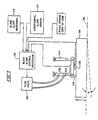
- cross slope control means comprising a blade slope control processor 136 in the illustrated embodiment is connected and responsive to the input device 118, to the angle sensors 120 and 128A or 128B, and to the first and second slope sensors 130 and 134 to control the blade slope angle B to maintain the desired cross slope angle C even when the motorgrader 100 is operated in a crabbed steering orientation as shown in Fig. 2.
- the first and second slope sensors 130 and 134 can comprise, among other available devices, fluid filed vials which form electrolytic potentiometers for monitoring the blade slope angle and the travel slope angle, respectively.
- the rotation angle A of the steering unit 106 relative to the drive unit 102 and the angle of rotation R of the blade 114 are not measured in the horizontal plane unless the blade slope angle B and the direction of travel slope angle L are both equal to zero. Since, the blade slope angle B and/or the direction of travel slope angle L are oftentimes not equal to zero, the rotation angles A and R thus include a slight error as compared to the angles A and R measured in the horizontal plane. While the errors could be corrected or compensated for in the present invention, the effects of the errors are neglible and therefore are ignored and will not be referred to further herein.
- a blade cross slope control system operable in accordance with the present invention for the grader blade 114 of the motorgrader 100 is shown in schematic block diagram form from a rear view of the grader blade 114.
- the elevation of the ring 116 and hence the elevation of the blade 114 is controlled by a pair of hydraulic cylinders 138 and 140 which are well known and hence only shown schematically in the block diagram of Fig. 3.
- the blade slope control processor 136 controls the cylinder 138 via a flow valve 142 with the cylinder 140 being controlled by an operator of the motorgrader 100 or an elevation positioning device (not shown), such as a laser control system or a string line control system, which is well known in the art and hence not described herein.
- FIG. 4 is a line drawing illustrating motorgrader movement and the relative positioning of components of a motorgrader operating in an articulated frame orientation or a crabbed steering mode.
- the following angular orientations are monitored or controlled by the slope control processor 136: B - the required blade slope angle of the blade 114 relative to horizontal; A - the angle of rotation of the steering unit 106 relative to the drive unit 102; R - the angle of rotation of the blade 114 relative to the steering unit 106; L - the direction of travel slope angle of the motorgrader 100; and, C - the desired cross slope angle as selected by the operator using the blade slope reference 118.
- Equation (a) is utilized by the blade slope control processor 136 to determine the blade slope angle B required to maintain the desired cross slope for a cut being performed by the motorgrader 100.
- the method for controlling the cross slope angle of a surface being worked by the motorgrader 100 comprises the steps of: selecting a desired cross slope angle C; sensing the angle of rotation R of the blade 114 relative to the steering unit 106; sensing the angle of rotation A of the steering unit 106 relative to the drive unit 102; sensing the blade slope angle B of the blade 114 relative to horizontal 132; sensing the direction of travel slope L of the motor grader 100; and controlling the blade slope angle B as a function of the desired cross slope angle C, the blade rotation angle R, the steering unit rotation angle A, and the motorgrader direction of travel slope angle L to maintain the desired cross slope C when the motorgrader 100 is operated in a crabbed steering position.
- the step of sensing the angle of rotation R of the steering unit 106 relative to the drive unit 102 may comprise the step of installing an angle sensor 128A at an articulation joint 110 interconnecting the steering unit 106 to the drive unit 102 or the step of installing an angle sensor 128B adjacent and coupled to the front steering wheels 108, as preferred for a given application.
Abstract
Description
- The present invention relates generally to a motorgrader having a two-part articulated frame defined by a rear drive unit and a front steering unit which can be rotated or pivoted relative to the drive unit and, more particularly, to an improved method and apparatus for controlling the cross slope angle cut by such a motorgrader while the motorgrader is being operated with the steering unit in a pivoted position relative to the drive unit.
- It is important to be able to grade surfaces during the construction of roadbeds, runways, parking lots and the like so that the grade and cross slope closely approximate the finished surface. In this way, the pavement is of a uniform thickness and strength. Highly skilled motorgrader operators can perform grading operations manually to produce acceptable grades and cross slopes. However, due to time pressures and the limited number of highly skilled operators, automatic control systems have been developed to assist operators and reduce the time and skill required to obtain acceptable grading.
- One such system permits a motorgrader operator to preset the slope of the blade and maintain that slope by servo valves or the like activated by a blade slope sensor. The blade slope sensor is mounted on the blade or a blade supporting structure. While these systems may be made to accurately reflect the blade slope relative to horizontal, they do not always reflect the true cross slope of the cut being made by the motorgrader, i. e. the slope normal to the direction of travel of the motorgrader. For example, errors occur when the blade is not positioned perpendicular to the direction of travel which is normally the case during operation when dirt is to be moved to one side or the other of the motorgrader.
- To overcome these problems, a motorgrader control system was developed to account for the angular positioning of the blade relative to the direction of travel of the motorgrader and also the inclination or slope assumed by the motorgrader. An example of such a control system is disclosed in U. S. Patent No. 3,786,871 and is a great improvement over the previously available slope preset system. Unfortunately, the disclosed system is not effective for all operating modes of motorgraders.
- Most modern motorgraders have a two-part articulated frame defined by a rear drive unit and a front steering unit which can be rotated or pivoted relative to the drive unit. Oftentimes it is required or desireable to operate a motorgrader with the front steering unit articulated at an angle relative to the rear drive unit, for example to position the drive unit on firm ground. When a motorgrader is operated in an articulated position and travelling in the direction defined by and in-line with the rear drive unit, the operating position is referred to as a "crabbed" steering position due to the movement of the motorgrader in an indirect or diagonal manner as a crab moves. For crabbed steering, the disclosed control system is ineffective .
- Accordingly, there is a need for an improved method and apparatus for operating a motorgrader having a two-part articulated frame to maintain a desired cross slope when the motorgrader is operated in a crabbed steering position.
- This need is met by the method and apparatus of the present invention for controlling the cross slope angle cut by the blade of an articulated frame motorgrader wherein the articulation angle of the motorgrader frame is sensed and used in the calculation of the blade slope angle required to maintain a selected cross slope angle. The blade slope is then controlled so that the sensed blade slope angle is substantially equal to the calculated blade slope angle to maintain the desired cross slope even when the motorgrader is operated in a crabbed steering position. The articulation angle of the motorgrader may be sensed directly at a frame articulation joint or remotely at the steering wheels of the motorgrader.
- In accordance with one aspect of the present invention, apparatus is provided for controlling the cross slope angle of a surface being worked by a motorgrader having a two-part articulated frame defined by a rear drive unit including rear drive wheels and a front steering unit which can be rotated relative to the drive unit and including front steering wheels. A blade is supported upon the steering unit for rotation about a generally vertical axis with the blade being mounted for adjustment of the elevations of its ends to define a blade slope angle relative to horizontal. The apparatus comprises input means for selecting a desired cross slope angle, first angle sensor means for sensing the angle of rotation of the blade relative to the steering unit, and second angle sensor means for sensing the angle of rotation of the steering unit relative to the drive unit. First slope sensor means sense the blade slope angle of the blade relative to horizontal and second slope sensor means sense the direction of travel slope angle of the motorgrader. Cross slope control means is connected to the input means, to the first and second angle sensor means, and to the first and second slope sensor means for controlling the blade slope angle to maintain the desired cross slope when the motorgrader is operated in a crabbed steering position.
- The second angle sensor means may be mounted at an articulation joint interconnecting the steering unit to the drive unit of the motorgrader or adjacent and coupled to the front steering wheels of the motorgrader, as preferred for a given application. The blade slope angle required to maintain the desired cross slope may be calculated by the cross slope control means using the equation: tan B = (sin (A+R))(tan L) + (cos (A+R))(tan C) where B is the required blade slope angle of the blade relative to horizontal; A is the angle of rotation of the steering unit relative to the drive unit; R is the angle of rotation of the blade relative to the steering unit; L is the direction of travel slope angle of the motorgrader; and C is the desired cross slope angle. The cross slope control means then controls the blade slope so that the sensed blade slope angle is substantially equal to the calculated blade slope angle to maintain the desired cross slope when the motorgrader is operated in a crabbed steering position.
- In accordance with another aspect of the present invention, a method is provided for controlling the cross slope angle of a surface being worked by a motorgrader having a two-part articulated frame defined by a rear drive unit including rear drive wheels and a front steering unit which can be rotated relative to the drive unit and including front steering wheels. A blade is supported upon the steering unit for rotation about a generally vertical axis with the blade being mounted for adjustment of the elevations of its ends to define a blade slope angle relative to horizontal. The method for controlling the cross slope angle of a surface being worked by the motorgrader comprises the steps of: selecting a desired cross slope angle; sensing the angle of rotation of the blade relative to the steering unit; sensing the angle of rotation of the steering unit relative to the drive unit; sensing the blade slope angle of the blade relative to horizontal; sensing the direction of travel slope of the motor grader; and controlling the blade slope angle as a function of the desired cross slope angle, the blade rotation angle, the steering unit rotation angle, and the motorgrader direction of travel slope angle to maintain the desired cross slope when the motorgrader is operated in a crabbed steering position.
- The step of controlling the blade slope angle as a function of the desired cross slope angle, the blade rotation angle, the steering unit rotation angle, and the motorgrader direction of travel slope angle may comprise the steps of: calculating a blade slope angle required for a desired cross slope using the equation: tan B = (sin (A+R))(tan L) + (cos (A+R))(tan C) where B is the required blade slope angle of the blade relative to horizontal; A is the angle of rotation of the steering unit relative to the drive unit; R is the angle of rotation of the blade relative to the steering unit; L is the direction of travel slope angle of the motorgrader; and, C is the desired cross slope angle, and controlling the blade slope so that the sensed blade slope angle is substantially equal to the calculated blade slope angle to maintain the desired cross slope when the motorgrader is operated in a crabbed steering position. The step of sensing the angle of rotation of the steering unit relative to the drive unit may comprise the step of installing an angle sensor at an articulation joint interconnecting the steering unit to the drive unit or the step of installing an angle sensor adjacent and coupled to the front steering wheels, as preferred for a given application.
- It is thus an object of the present invention to provide an improved method and apparatus for controlling the cross slope angle cut by the blade of an articulated frame motorgrader which is effective while the motorgrader is operated in a crabbed steering position; to provide an improved method and apparatus for controlling the cross slope angle cut by the blade of an articulated frame motorgrader by sensing the articulation angle of the motorgrader frame, using the sensed articulation angle to calculate the blade slope angle required to maintain a selected cross slope angle and controlling the blade slope so that the sensed blade slope angle is substantially equal to the calculated blade slope angle; and, to provide an improved method and apparatus for controlling the cross slope angle cut by the blade of an articulated frame motorgrader by sensing the articulation angle of the motorgrader frame at or near an articulation joint or the front steering wheels which also reflect the articulation angle, using the sensed articulation angle to calculate the blade slope angle required to maintain a selected cross slope angle, and controlling the blade slope so that the sensed blade slope angle is substantially equal to the calculated blade slope angle.
- Other objects and advantages of the invention will be apparent from the following description, the accompanying drawings and the appended claims.
- In order that the invention may be more readily understood, reference will now be made to the accompanying drawings, in which:
- Figs. 1 and 2 are schematic plan views of articulated frame motorgraders illustrating straight frame operation and articulated frame operation, respectively;
- Fig. 3 is a schematic block diagram showing the application of the present invention for cross slope control in a motorgrader; and
- Fig. 4 is a line drawing illustrating motorgrader movement and relative orientations of components of a motorgrader for articulated frame, crabbed steering operation.
- Reference is now made to the drawing figures wherein Figs. 1 and 2 schematically illustrate a two-part articulated
frame motorgrader 100 in plan view. Themotorgrader 100 includes arear drive unit 102 includingrear drive wheels 104 and afront steering unit 106 includingfront steering wheels 108. Thefront steering unit 106 is connected to therear drive unit 102 by aframe articulation joint 110 so that thesteering unit 106 can be rotated relative to thedrive unit 102 to assist thesteering wheels 108 in steering themotorgrader 100 and to permit "crabbed" steering of themotorgrader 100 as shown in Fig. 2. While straight frame operation as shown in Fig. 1 is used much of the time, it is often desireable to operate themotorgrader 100 with thesteering unit 106 rotated at a selectable angle A relative to thedrive unit 102, but traveling in adirection 112 defined by and in-line with thedrive unit 102, which is referred to as crabbed steering. - A
blade 114 is supported upon thesteering unit 106 by means of a draw bar/turntable arrangement commonly referred to as a "ring" or "circle" 116 so that theblade 114 can be rotated about a generally vertical axis collinear with the center of thecircle 116. When themotorgrader 100 is operated in the straight frame orientation of Fig. 1, the control system of U. S. Patent No. 3,786,871, which is incorporated herein by reference, or an equivalent system is capable of maintaining a desired cross slope, i. e. the slope normal to the direction of travel of themotorgrader 100, for the cut being made by themotorgrader 100. Unfortunately, when themotorgrader 100 is operated in the articulated frame orientation of Fig. 2 or crabbed steering mode, such control systems are ineffective and an operator must again resort to manual control of the grading operation. - In accordance with the present invention, a method and apparatus are provided to control the cross slope of the cut being made by the
motorgrader 100 even when themotorgrader 100 is operated in a crabbed steering postion. The apparatus required for operation of the present invention includes input means comprising aninput device 118, see Fig. 3, such as a keyboard or the like, for selecting a desired cross slope angle C. Theinput device 118 is typically mounted in the operator's cab (not shown) for themotorgrader 100. First angle sensor means comprising anangle sensor 120 senses the angle of rotation R of theblade 114 relative to thesteering unit 106. As shown in the drawing figures the blade angle of rotation R is measured relative to aline 124 perpendicular to theaxis 126 of thesteering unit 106 so that a zero degree blade rotation angle corresponds to positioning theblade 114 perpendicular to thesteering unit 106. Further, for proper operation of the present invention, thecircle 116 must remain centered relative to thesteering unit 106 and not be side-shifted. - Second angle sensor means comprising an
angle sensor steering unit 106 relative to thedrive unit 102. Theangle sensor 128A is mounted at or near thearticulation joint 110 interconnecting thesteering unit 106 to thedrive unit 102 so that the rotation angle A is directly sensed while thesensor 128B, which is mounted adjacent and coupled to thefront steering wheels 108, senses the rotation angle A indirectly, see Fig. 2. As shown in Figs. 1 and 2, thesensor 128B is mounted generally between thefront steering wheels 108 and coupled thereto for example bysteering linkages 108A. Of course, thesensor 128B could be positioned directly adjacent to one of thefront steering wheels 108 to more directly sense the rotation angle A, if desired. Theangle sensors - First slope sensor means comprising a
slope sensor 130 senses the blade slope angle B of theblade 114 relative to horizontal 132, see Figs. 3 and 4. As shown, theslope sensor 130 is mounted on thering 116; however, it can be mounted on theblade 114 or other blade supporting structure as preferred for a given application. Second slope sensor means comprising aslope sensor 134 mounted on therear drive unit 102 senses the direction of travel slope angle L of themotorgrader 100. Finally, cross slope control means comprising a bladeslope control processor 136 in the illustrated embodiment is connected and responsive to theinput device 118, to theangle sensors second slope sensors motorgrader 100 is operated in a crabbed steering orientation as shown in Fig. 2. The first andsecond slope sensors - It is noted that the rotation angle A of the
steering unit 106 relative to thedrive unit 102 and the angle of rotation R of theblade 114 are not measured in the horizontal plane unless the blade slope angle B and the direction of travel slope angle L are both equal to zero. Since, the blade slope angle B and/or the direction of travel slope angle L are oftentimes not equal to zero, the rotation angles A and R thus include a slight error as compared to the angles A and R measured in the horizontal plane. While the errors could be corrected or compensated for in the present invention, the effects of the errors are neglible and therefore are ignored and will not be referred to further herein. - In Fig. 3, a blade cross slope control system operable in accordance with the present invention for the
grader blade 114 of themotorgrader 100 is shown in schematic block diagram form from a rear view of thegrader blade 114. The elevation of thering 116 and hence the elevation of theblade 114 is controlled by a pair ofhydraulic cylinders slope control processor 136 controls thecylinder 138 via aflow valve 142 with thecylinder 140 being controlled by an operator of themotorgrader 100 or an elevation positioning device (not shown), such as a laser control system or a string line control system, which is well known in the art and hence not described herein. It should be apparent that other earthworking tools in addition to a grader blade can be mounted in a variety of ways such that the blade or other tool is supported by a pair of hydraulic cylinders, such as thecylinders - An equation will now be developed for the operation of the blade
slope control processor 136 of Fig. 3 with reference to Fig. 4 which is a line drawing illustrating motorgrader movement and the relative positioning of components of a motorgrader operating in an articulated frame orientation or a crabbed steering mode. The following angular orientations are monitored or controlled by the slope control processor 136: B - the required blade slope angle of theblade 114 relative to horizontal; A - the angle of rotation of thesteering unit 106 relative to thedrive unit 102; R - the angle of rotation of theblade 114 relative to thesteering unit 106; L - the direction of travel slope angle of themotorgrader 100; and, C - the desired cross slope angle as selected by the operator using theblade slope reference 118. The line segment designations are relative and utilized only to derive equation (a) as should be apparent.
tan B = blade slope angle (rise/run) = j/h
tan L = travel slope angle (rise/run) = (j-c)/(m+f)
tan C = cross slope = c/a
h = SQRT((m+f)2 + a2)
j = (m+f)tan L + c
tan B = ((m+f)tan L + c)/SQRT((m+f)2 + a2)
tan B = atan(A + R)(tan L) + a(tan C)/SQRT ((atan(A + R))2 + a2)
tan B = tan(A + R)(tan L) + tan C/SQRT (tan2(A+R) + 1)
cos (A + R) = 1/SQRT (tan2(A + R) + 1)
tan B = (cos (A + R))(tan(A + R))(tan L) + (cos(A + R))(tan C)
(a) tan B = (sin (A + R))(tan L) + (cos (A + R))(tan C)
where B is the required blade slope angle of the blade relative to horizontal; A is the angle of rotation of the steering unit relative to the drive unit; R is the angle of rotation of the blade relative to the steering unit; L is the direction of travel slope angle of the motorgrader; and C is the desired cross slope angle. Equation (a) is utilized by the bladeslope control processor 136 to determine the blade slope angle B required to maintain the desired cross slope for a cut being performed by themotorgrader 100. The cross slope control means or bladeslope control processor 136 then controls the blade slope via theflow valve 142 and thecylinder 138 so that the sensed blade slope angle B is maintained substantially equal to the calculated blade slope angle B to maintain the desired cross slope angle C even when themotorgrader 100 is operated in a crabbed steering position as shown in Fig. 2. It is noted that the bladeslope control processor 136 also functions properly to maintain the cross slope angle C when themotorgrader 100 is operated in a stratight frame mode since for such operation A = 0 and it can be seen that the equation for B is still accurate. - While the method of operating the disclosed apparatus should be apparent from the foregoing description, a brief description will now be provided for the sake of clarity. The method for controlling the cross slope angle of a surface being worked by the
motorgrader 100 comprises the steps of: selecting a desired cross slope angle C; sensing the angle of rotation R of theblade 114 relative to thesteering unit 106; sensing the angle of rotation A of thesteering unit 106 relative to thedrive unit 102; sensing the blade slope angle B of theblade 114 relative to horizontal 132; sensing the direction of travel slope L of themotor grader 100; and controlling the blade slope angle B as a function of the desired cross slope angle C, the blade rotation angle R, the steering unit rotation angle A, and the motorgrader direction of travel slope angle L to maintain the desired cross slope C when themotorgrader 100 is operated in a crabbed steering position. - The step of controlling the blade slope angle as a function of the desired cross slope angle C, the blade rotation angle R, the steering unit rotation angle A, and the
motorgrader 100 direction of travel slope angle L may comprise the steps of: calculating a blade slope angle B required for a desired cross slope C using the equation: tan B = (sin (A+R))(tan L) + (cos (A+R))(tan C) where B is the required blade slope angle of theblade 114 relative to horizontal 132; A is the angle of rotation of thesteering unit 106 relative to thedrive unit 102; R is the angle of rotation of theblade 114 relative to thesteering unit 106; L is the direction of travel slope angle of themotorgrader 100; and, C is the desired cross slope angle, and controlling the blade slope so that the sensed blade slope angle B is substantially equal to the calculated blade slope angle B to maintain the desired cross slope C when themotorgrader 100 is operated in a crabbed steering position. - The step of sensing the angle of rotation R of the
steering unit 106 relative to thedrive unit 102 may comprise the step of installing anangle sensor 128A at an articulation joint 110 interconnecting thesteering unit 106 to thedrive unit 102 or the step of installing anangle sensor 128B adjacent and coupled to thefront steering wheels 108, as preferred for a given application. - Having thus described the method and apparatus for controlling motorgrader cross slope cut of the present invention in detail and by reference to preferred embodiments thereof, it will be apparent that modifications and variations are possible without departing from the scope of the invention as defined in the appended claims.
Claims (8)
input means (118) for selecting a desired cross slope angle (C);
first angle sensor means (120) for sensing the angle of rotation of the blade (114) relative to the steering unit (106);
second angle sensor means (128A, 128B) for sensing the angle of rotation of said steering unit (106) relative to the drive unit (102);
first slope sensor means (130) for sensing the blade slope angle (B) of said blade (114) relative to horizontal (132);
second slope sensor means (134) for sensing the direction of travel slope angle (L) of said motorgrader (100); and
cross slope control means (136) connected to said input means (118), to said first and second angle sensor means (114, 128A, 128B), and to said first and second slope sensor means (130, 134) for controlling said blade slope angle (B) to maintain said desired cross slope when said motorgrader (100) is operated in a crabbed steering position.
tan B = (sin (A+R))(tan L) + (cos (A+R))(tan C)
where B is the required blade slope angle of said blade (114) relative to horizontal (132); A is the angle of rotation of said steering unit (106) relative to said drive unit (102); R is the angle of rotation of said blade (114) relative to said steering unit (106); L is the direction of travel slope angle of said motorgrader (100); and C is the desired cross slope angle, and said cross slope control means (136) controls said blade slope so that the sensed blade slope angle (B) is substantially equal to the calculated blade slope angle to maintain said desired cross slope when said motorgrader (100) is operated in a crabbed steering position.
selecting a desired cross slope angle (C);
sensing the angle of rotation (R) of the blade (114) relative to the steering unit (106);
sensing the angle of rotation (A) of said steering unit (106) relative to the drive unit (102);
sensing the blade slope angle (B) of said blade (114) relative to horizontal (132);
sensing the direction of travel slope (L) of said motorgrader (100); and
controlling said blade slope angle (B) as a function of the desired cross slope angle (C), the blade rotation angle (R), the steering unit rotation angle (A), and the motorgrader direction of travel slope angle (L) to maintain said desired cross slope when said motorgrader (100) is operated in a crabbed steering position.
tan B = (sin (A+R))(tan L) + (cos (A+R))(tan C)
where B is the required blade slope angle of said blade (114) relative to horizontal (132); A is the angle of rotation of said steering unit (106) relative to said drive unit (102); R is the angle of rotation of said blade (114) relative to said steering unit (106); L is the direction of travel slope angle of said motorgrader (100); and, C is the desired cross slope angle, and controlling the blade slope so that the sensed blade slope angle (B) is substantially equal to the calculated blade slope angle (B) to maintain said desired cross slope when said motorgrader (100) is operated in a crabbed steering position.
Applications Claiming Priority (2)
| Application Number | Priority Date | Filing Date | Title |
|---|---|---|---|
| US07/372,909 US4926948A (en) | 1989-06-28 | 1989-06-28 | Method and apparatus for controlling motorgrader cross slope cut |
| US372909 | 1989-06-28 |
Publications (2)
| Publication Number | Publication Date |
|---|---|
| EP0405725A2 true EP0405725A2 (en) | 1991-01-02 |
| EP0405725A3 EP0405725A3 (en) | 1991-11-27 |
Family
ID=23470136
Family Applications (1)
| Application Number | Title | Priority Date | Filing Date |
|---|---|---|---|
| EP19900304714 Withdrawn EP0405725A3 (en) | 1989-06-28 | 1990-05-01 | Method and apparatus for controlling motorgrader cross slope cut |
Country Status (5)
| Country | Link |
|---|---|
| US (1) | US4926948A (en) |
| EP (1) | EP0405725A3 (en) |
| JP (1) | JPH0339526A (en) |
| AU (1) | AU5472790A (en) |
| CA (1) | CA2015607A1 (en) |
Cited By (3)
| Publication number | Priority date | Publication date | Assignee | Title |
|---|---|---|---|---|
| US6108076A (en) * | 1998-12-21 | 2000-08-22 | Trimble Navigation Limited | Method and apparatus for accurately positioning a tool on a mobile machine using on-board laser and positioning system |
| US6253160B1 (en) | 1999-01-15 | 2001-06-26 | Trimble Navigation Ltd. | Method and apparatus for calibrating a tool positioning mechanism on a mobile machine |
| US10620004B2 (en) | 2017-01-20 | 2020-04-14 | Caterpillar Inc. | Surveying system and method using mobile work machine |
Families Citing this family (24)
| Publication number | Priority date | Publication date | Assignee | Title |
|---|---|---|---|---|
| US5078215A (en) * | 1990-05-29 | 1992-01-07 | Spectra-Physics Laserplane, Inc. | Method and apparatus for controlling the slope of a blade on a motorgrader |
| US5107932A (en) * | 1991-03-01 | 1992-04-28 | Spectra-Physics Laserplane, Inc. | Method and apparatus for controlling the blade of a motorgrader |
| JP3305118B2 (en) * | 1994-06-23 | 2002-07-22 | 三菱重工業株式会社 | Blade rotation angle detection method |
| US6152237A (en) * | 1998-12-11 | 2000-11-28 | Caterpillar Inc. | Method for automatically controlling the articulation angle of a motor grader |
| US6112145A (en) * | 1999-01-26 | 2000-08-29 | Spectra Precision, Inc. | Method and apparatus for controlling the spatial orientation of the blade on an earthmoving machine |
| US6275758B1 (en) * | 1999-06-29 | 2001-08-14 | Caterpillar Inc. | Method and apparatus for determining a cross slope of a surface |
| US7588088B2 (en) * | 2006-06-13 | 2009-09-15 | Catgerpillar Trimble Control Technologies, Llc | Motor grader and control system therefore |
| US7730644B2 (en) * | 2007-03-15 | 2010-06-08 | 1708828 Ontario Inc. | Snowplow with pivoting sideblades |
| US7810260B2 (en) * | 2007-12-21 | 2010-10-12 | Caterpillar Trimble Control Technologies Llc | Control system for tool coupling |
| US20100129152A1 (en) * | 2008-11-25 | 2010-05-27 | Trimble Navigation Limited | Method of covering an area with a layer of compressible material |
| US8985233B2 (en) | 2010-12-22 | 2015-03-24 | Caterpillar Inc. | System and method for controlling a rotation angle of a motor grader blade |
| US8794867B2 (en) | 2011-05-26 | 2014-08-05 | Trimble Navigation Limited | Asphalt milling machine control and method |
| US8548691B2 (en) * | 2011-10-06 | 2013-10-01 | Komatsu Ltd. | Blade control system, construction machine and blade control method |
| US9103098B2 (en) * | 2012-08-07 | 2015-08-11 | Caterpillar Inc. | Auto crab operation for motor grader |
| US8948981B2 (en) | 2012-12-20 | 2015-02-03 | Caterpillar Inc. | System and method for optimizing a cut location |
| US9014924B2 (en) | 2012-12-20 | 2015-04-21 | Caterpillar Inc. | System and method for estimating material characteristics |
| US9228315B2 (en) | 2012-12-20 | 2016-01-05 | Caterpillar Inc. | System and method for modifying a path for a machine |
| US9014922B2 (en) | 2012-12-20 | 2015-04-21 | Caterpillar Inc. | System and method for optimizing a cut location |
| TWI513993B (en) | 2013-03-26 | 2015-12-21 | Ind Tech Res Inst | 3-axis magnetic field sensor, fabrication method of magnetic sensing structure and magnetic field sensing circuit |
| US20140326471A1 (en) * | 2013-05-03 | 2014-11-06 | Caterpillar Inc. | Motor Grader Cross Slope Control With Articulation Compensation |
| US9428884B2 (en) * | 2014-03-17 | 2016-08-30 | Caterpillar Inc. | Articulation covering complete range of steering angles in automatic articulation feature |
| US9469967B2 (en) | 2014-09-12 | 2016-10-18 | Caterpillar Inc. | System and method for controlling the operation of a machine |
| WO2018179962A1 (en) * | 2017-03-30 | 2018-10-04 | 株式会社小松製作所 | Control system for work vehicle, method for setting trajectory of work machine, and work vehicle |
| JP2023179888A (en) * | 2022-06-08 | 2023-12-20 | 株式会社小松製作所 | Work machine, method for controlling work machine, and system |
Citations (2)
| Publication number | Priority date | Publication date | Assignee | Title |
|---|---|---|---|---|
| US3786871A (en) * | 1971-07-26 | 1974-01-22 | Grad Line | Grader control |
| US4431060A (en) * | 1981-04-15 | 1984-02-14 | Caterpillar Tractor Co. | Earth working machine and blade condition control system therefor |
Family Cites Families (16)
| Publication number | Priority date | Publication date | Assignee | Title |
|---|---|---|---|---|
| US2754499A (en) * | 1954-07-06 | 1956-07-10 | Raymond C Jost | Steering indicator |
| US2886299A (en) * | 1956-04-30 | 1959-05-12 | Union Carbide Corp | Bore mining apparatus having means to measure the angle between units thereof |
| US3250547A (en) * | 1965-02-16 | 1966-05-10 | Clark R Myers | Hydraulic control system for trailer trucks |
| US3791452A (en) * | 1971-03-17 | 1974-02-12 | Grad Line | Control system for road grader |
| US3833928A (en) * | 1973-01-08 | 1974-09-03 | S Gavit | Vehicle-trailer angular position sensor and indicator |
| CA1012760A (en) * | 1973-10-23 | 1977-06-28 | Honeywell Inc. | Slope control system |
| US3947839A (en) * | 1975-01-31 | 1976-03-30 | Frank Zigmant | Trailer angular direction sensor and indicator |
| US4008466A (en) * | 1975-11-07 | 1977-02-15 | Smith William V | Device for indicating angular position and depth of a towed vehicle |
| US4122390A (en) * | 1976-10-28 | 1978-10-24 | Gerhard Kollitz | Apparatus for sensing and indicating the angular relationship between a towing and a towed vehicle |
| US4213503A (en) * | 1977-01-17 | 1980-07-22 | Honeywell Inc. | Slope control system |
| EP0067606A1 (en) * | 1981-06-11 | 1982-12-22 | GKN Group Services Limited | Steering of vehicles |
| JPS58173232A (en) * | 1982-04-02 | 1983-10-12 | Komatsu Ltd | Automatic controller for motor grader |
| JPS59102023A (en) * | 1982-12-01 | 1984-06-12 | Komatsu Ltd | Automatic controller for motor glader |
| US4545439A (en) * | 1983-07-01 | 1985-10-08 | Sellett Andrew J | Apparatus for determining the true cross slope of a blade |
| US4696486A (en) * | 1986-01-21 | 1987-09-29 | Deere & Company | Rear steer angle indicator for articulating vehicle |
| DE3610666C2 (en) * | 1986-03-29 | 1993-10-14 | Orenstein & Koppel Ag | Bulldozer |
-
1989
- 1989-06-28 US US07/372,909 patent/US4926948A/en not_active Expired - Lifetime
-
1990
- 1990-04-27 CA CA002015607A patent/CA2015607A1/en not_active Abandoned
- 1990-05-01 EP EP19900304714 patent/EP0405725A3/en not_active Withdrawn
- 1990-05-07 AU AU54727/90A patent/AU5472790A/en not_active Abandoned
- 1990-05-17 JP JP2128085A patent/JPH0339526A/en active Pending
Patent Citations (2)
| Publication number | Priority date | Publication date | Assignee | Title |
|---|---|---|---|---|
| US3786871A (en) * | 1971-07-26 | 1974-01-22 | Grad Line | Grader control |
| US4431060A (en) * | 1981-04-15 | 1984-02-14 | Caterpillar Tractor Co. | Earth working machine and blade condition control system therefor |
Cited By (3)
| Publication number | Priority date | Publication date | Assignee | Title |
|---|---|---|---|---|
| US6108076A (en) * | 1998-12-21 | 2000-08-22 | Trimble Navigation Limited | Method and apparatus for accurately positioning a tool on a mobile machine using on-board laser and positioning system |
| US6253160B1 (en) | 1999-01-15 | 2001-06-26 | Trimble Navigation Ltd. | Method and apparatus for calibrating a tool positioning mechanism on a mobile machine |
| US10620004B2 (en) | 2017-01-20 | 2020-04-14 | Caterpillar Inc. | Surveying system and method using mobile work machine |
Also Published As
| Publication number | Publication date |
|---|---|
| US4926948A (en) | 1990-05-22 |
| AU5472790A (en) | 1991-01-03 |
| CA2015607A1 (en) | 1990-12-28 |
| JPH0339526A (en) | 1991-02-20 |
| EP0405725A3 (en) | 1991-11-27 |
Similar Documents
| Publication | Publication Date | Title |
|---|---|---|
| EP0405725A2 (en) | Method and apparatus for controlling motorgrader cross slope cut | |
| US5107932A (en) | Method and apparatus for controlling the blade of a motorgrader | |
| US6389345B2 (en) | Method and apparatus for determining a cross slope of a surface | |
| US6269885B1 (en) | Blade height control system for a motorized grader | |
| US8141650B2 (en) | Automatic depth correction based on blade pitch | |
| EP0731221A1 (en) | Linear excavating control device for a hydraulic power shovel | |
| CN110966979B (en) | Sensor for motor grader | |
| EP0735202A1 (en) | Hydraulically operated machine, control therefor and method of control thereof | |
| CN108779616B (en) | Control method of motor grader, motor grader and operation management system of motor grader | |
| US6209232B1 (en) | Construction machine with function of measuring finishing accuracy of floor face smoothed thereby | |
| EP0397534B1 (en) | Screed slope controller for a paver | |
| US6530721B2 (en) | Method for control system setup | |
| US20220112684A1 (en) | Grader and slope scraping control method and device thereof | |
| CN111441406B (en) | Bird's eye view calibration for slope control | |
| US4545439A (en) | Apparatus for determining the true cross slope of a blade | |
| US4085805A (en) | Earth working machine with elevation control for tool thereof | |
| US20020127058A1 (en) | Control system and method for controlling a screed head | |
| JPS6337210B2 (en) | ||
| JPH0657782A (en) | Automatic blade controlling device for bulldozer | |
| JP2673599B2 (en) | Blade position control device for tracked vehicle | |
| JP2907684B2 (en) | Backhoe | |
| US10508409B2 (en) | Machine with a boom assembly and connection member | |
| JP3389303B2 (en) | Linear excavation control device of hydraulic excavator | |
| JPH0588347B2 (en) | ||
| WO2022245556A1 (en) | Blade position system |
Legal Events
| Date | Code | Title | Description |
|---|---|---|---|
| PUAI | Public reference made under article 153(3) epc to a published international application that has entered the european phase |
Free format text: ORIGINAL CODE: 0009012 |
|
| AK | Designated contracting states |
Kind code of ref document: A2 Designated state(s): DE FR GB NL SE |
|
| 17P | Request for examination filed |
Effective date: 19901220 |
|
| PUAL | Search report despatched |
Free format text: ORIGINAL CODE: 0009013 |
|
| RAP1 | Party data changed (applicant data changed or rights of an application transferred) |
Owner name: SPECTRA-PHYSICS LASERPLANE, INC. |
|
| AK | Designated contracting states |
Kind code of ref document: A3 Designated state(s): DE FR GB NL SE |
|
| STAA | Information on the status of an ep patent application or granted ep patent |
Free format text: STATUS: THE APPLICATION HAS BEEN WITHDRAWN |
|
| 18W | Application withdrawn |
Withdrawal date: 19930613 |