EP0405394A2 - Subscriber equipment for transmitting temporarily stored data to a paging receiver fitted with an acoustical and/or optical output device - Google Patents
Subscriber equipment for transmitting temporarily stored data to a paging receiver fitted with an acoustical and/or optical output device Download PDFInfo
- Publication number
- EP0405394A2 EP0405394A2 EP90112030A EP90112030A EP0405394A2 EP 0405394 A2 EP0405394 A2 EP 0405394A2 EP 90112030 A EP90112030 A EP 90112030A EP 90112030 A EP90112030 A EP 90112030A EP 0405394 A2 EP0405394 A2 EP 0405394A2
- Authority
- EP
- European Patent Office
- Prior art keywords
- subscriber
- subscriber device
- paging
- microprocessor
- call
- Prior art date
- Legal status (The legal status is an assumption and is not a legal conclusion. Google has not performed a legal analysis and makes no representation as to the accuracy of the status listed.)
- Granted
Links
Images

Classifications
-
- H—ELECTRICITY
- H04—ELECTRIC COMMUNICATION TECHNIQUE
- H04W—WIRELESS COMMUNICATION NETWORKS
- H04W88/00—Devices specially adapted for wireless communication networks, e.g. terminals, base stations or access point devices
- H04W88/18—Service support devices; Network management devices
- H04W88/185—Selective call encoders for paging networks, e.g. paging centre devices
-
- H—ELECTRICITY
- H04—ELECTRIC COMMUNICATION TECHNIQUE
- H04M—TELEPHONIC COMMUNICATION
- H04M1/00—Substation equipment, e.g. for use by subscribers
- H04M1/64—Automatic arrangements for answering calls; Automatic arrangements for recording messages for absent subscribers; Arrangements for recording conversations
- H04M1/65—Recording arrangements for recording a message from the calling party
- H04M1/658—Means for redirecting recorded messages to other extensions or equipment
Definitions
- the invention relates to a subscriber device according to the preamble of patent claim 1.
- the automatic dialer With the answering machine the message of the caller is recorded, then the automatic dialer is activated and the owner of the answering machine is automatically called via the European paging service or via the telecommunications network. For this purpose, the automatic dialer initiates a connection based on one or more previously stored phone numbers and when the called subscriber reports, the subscriber is asked (announcement text) to bring the answering machine owner to the phone.
- the message from the caller recorded by the answering machine can then be queried remotely by the owner of the answering machine via the telecommunications network using the code transmitter carried along. The call charges are not borne by the called party, but by the owner of the answering machine.
- the pager can be reached via a maximum of four numbers.
- code signals are formed which are fed to the VHF transmitters connected to the paging center for call transmission.
- the transmitted code signals are received and decoded by the pager. If the code set in the decoder matches the code received, an acoustic and an optical signal are resolved. The meaning of the code signals must be agreed between the pager and the calling party.
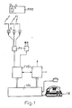
- a paging service referred to as a city call and shown in FIG. 1 is known, in which brief information is shown as digits or texts on the display D of the paging receiver FRE. These messages can be entered via the telephone set, telex, teletex or Btx terminals.
- City calls can transmit information in three call classes: Tone-only for tone pagers FRE, which can receive four agreed signals in accordance with the European paging service; Numeric for FRE numeric pagers to receive up to fifteen digits or special characters and Alphanumeric for FRE alphanumeric pagers to receive text (strings of digits and letters) up to eighty characters.
- City-Ruf is broadcast in regional zones (so-called call zones), with the coverage area covering approximately the entire catchment area of a large city.
- the paging network consists of the paging centers FVSt, the paging concentrators FK, the transmitters S and the paging receivers FRE.
- the paging exchange FVSt manages the subscriber data and controls the transmitters S via which a call is to be broadcast. Access from the public telecommunications networks to the paging network is possible with the same access code and depends only on the call class and the respective input device for the city call information.
- the end devices installed at the subscriber for the various postal services serve as input devices. For a numerical and text input from a simple telephone connection, special additional devices, for example, acoustically connectable DTMF transmitters, are required, since the FREF numeric paging receiver Require multi-frequency dialing (DTMF). If alphanumeric information is to be entered from a personal computer or home computer, it must be connected to an acoustic coupler or modem.
- DTMF FREF numeric paging receiver Require multi-frequency dialing
- a paging radio system for nationwide call networks in which not only voice announcements but also 10-digit numbers can be transmitted.
- a so-called adaptation transmission is provided in the paging center, which stores the dialing information of up to eighteen digits of the calling subscriber and also enables the calling subscriber to communicate with the call processor.
- a coupling of the adaptation transmission to a voice bus is provided for a time-limited voice message to the pager, a speech path being switched through from the caller's microphone to the pager's loudspeaker for a short time.
- Firefighters - calls can also be triggered by contacts.
- Answering machine and / or radio paging receiver can improve the accessibility of a called but absent subscriber. Due to the conception of the answering machine and the paging services, a fast message transmission is possible in the Subscriber device, especially answering machine, cached messages not possible.
- the invention is based on the object of designing a subscriber device in such a way that rapid transmission of temporarily stored messages to a radio paging receiver with an optical and / or acoustic output device is made possible.
- the subscriber device has the advantage that the calling subscriber can leave numeric, alphanumeric and spoken messages which are temporarily stored in the buffer of the subscriber device and are automatically transmitted to a pager with an optical and / or acoustic output device after the connection has been triggered. Another advantage is that the calling subscriber can transmit a message to a pager even if he does not know the paging subscriber number. If the subscriber device is designed in the form of an answering machine with message recording, it is not necessary for the calling subscriber with a view to a rapid transmission of his Message to reach the owner of the answering machine who is on the move via the paging service. Since the calling subscriber can leave his message, there are no two-way charges that are otherwise required, but the second call charge is borne by the owner of the answering machine.
- the new additional function of the subscriber device eliminates the need to call the owner of the answering machine while on the move. For the owner of the answering machine, the otherwise necessary call fee for the remote-controlled query of a message recorded by the answering machine of the caller is thus eliminated.
- the temporarily stored brief information can be shown as numbers or texts on the display of the pager.
- the radio call receiver also has an acoustic output device, voice announcements can also be transmitted in addition to this display of brief information on the display. Since modern answering machines are usually DTMF-capable and have facilities for forwarding calls via the European paging service, only the additional buffer is required as additional equipment.
- the embodiment of the subscriber device according to claim 2 has the advantage that modern comfort telephones with a DTMF-capable keyboard can be used to enter the message to be transmitted to the pager.
- the embodiment of the subscriber device according to claim 3 has the advantage that no additional device for entering the characters, i.e. Numbers or letters, is required.
- a paging arrangement is known from DE-OS 35 19 972, in which an arrangement for speech recognition is arranged in the paging center.
- This arrangement for speech recognition which is arranged centrally in the paging, performs a signal conversion of the numerical information spoken by the telephone subscriber into signals suitable for transmission via the paging transmitter.
- the acoustic control makes it possible for the calling subscriber to ensure that, for example, the correct telephone subscriber number for the pager is transmitted. If the subscriber device is voice-controlled and contains these devices for digital speech processing, the additional equipment expenditure to be provided for this is very low.
- the embodiment of the subscriber device according to claim 7 enables both remote monitoring of the subscriber device itself and remote monitoring of devices connected to the subscriber device.
- the radio paging receiver also has an acoustic output device
- acoustic room monitoring can also be carried out to supplement the function of alarm systems.
- Fig. 1 shows the structure of the City-Ruf paging service in the Federal Republic.
- the city call can also be used by the participants across borders, for example the paging service Alphapage in France, Teledrine in Italy and Europage in Great Britain. To do this, the City Ruf subscriber must log into an international European call zone. Due to the signal conversion in the subscriber device TE according to the invention, it is not necessary for the calling subscriber to enter his message using a special input device for paging information.
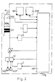
- the subscriber device TE shown in FIG. 2 is connected to the telecommunications network via the main connecting line AL.
- a microprocessor MP is arranged in the subscriber device TE and is connected to a number switch pulse contact NSI, an NSA contact NSA and a changeover switch S1. With the number switch pulse contact NSI pulse series are generated, the NSA contact is used to switch off the speech circuit during the dialing and with the switch S1 there is a switch to different message sources.
- the microprocessor MP is connected to a memory SP with dialing information (eg telephone numbers).
- the microprocessor MP takes over the function of an automatic dialing device and can also carry out a switching function.
- the microprocessor MP controls the exchange of switching information between the subscriber device TE and the control devices of the switching centers VSt or FVSt of the telecommunications network.
- the dialing information is generated in the subscriber device TE either with the number switch pulse contact NSI or with a generator G operating according to the multi-frequency code selection method.
- the subscriber device TE can, however, be used in all communication networks for switched connections, for example the answering machine can also be an integral part of a cordless telephone set, as is known from the magazine "JEI, June 89, p. 98 ff".
- a call signal arrives via the main connection line AL in the subscriber device TE, this is recognized by a call receiving circuit and a control signal for the microprocessor MP is triggered, which connects the call to the subscriber manufactures.
- the announcement text contained in the announcement memory ASP is read out and transmitted to the calling subscriber via the main connection line AL.
- the calling subscriber can either leave a spoken message, which is temporarily stored in the AZS recording memory for remote inquiry, or he gives with a telephone set that can generate signals using the multi-frequency code dialing method or with an acoustically coupled input device (code transmitter for generating DTMF characters) numeric messages for the radio paging receiver FRE.
- This numerical message can be, for example, the subscriber's telephone number.
- the digits are buffered in the buffer ZSP and the calling subscriber receives the final announcement.
- the microprocessor MP initiates a connection setup to the radio paging receiver FRE using the dialing information stored in the memory SP.
- the information in the buffer ZSP ie the sequence of digits in the case described, is read out and displayed on the optical output device D of the radio paging receiver FRE.
- the microprocessor MP reads out, for example when an alarm contact is actuated, the correspondingly entered message contained in the intermediate memory ZSP for transmission to the radio paging receiver FRE.
- the subscriber device TE contains a hybrid circuit GS with a transformer, but also electronic hybrid circuits with automatic line impedance adjustment and / or a line length-dependent gain control can also be used. Furthermore, a switchable amplifier V is connected to the microprocessor Mp, which ensures good voice quality, for example, during each phase of the message transmission. Furthermore, a receiver E for signals according to the DTMF method (double-tone multi-frequency method) is arranged in the subscriber device TE and is connected to the microprocessor MP. Modern answering machines generally contain the receiver E and the generator G. The receiver E is used to decode the code words required for remote access. With the generator G, the dial signals are generated. In the subscriber device TE according to the invention, the receiver E and the Generator G in addition to the signal conversion during the intermediate storage and transmission of the messages.
- DTMF method double-tone multi-frequency method
- the embodiment shown in FIG. 2 relates to the transmission of messages in the form of digits.
- a corresponding signal conversion is required in the subscriber device TE, with either telex, teletex or Btx terminals having to be installed as an input device for the calling subscriber, or a computer with an acoustic coupler or modem is.
- the speech signals supplied via the main connection line AL are fed to a speech analyzer SA in the subscriber device TE.
- a device SU for signal conversion of the recognized, spoken character is connected to the speech analyzer SA and the intermediate memory ZSP.
- the voice input can be carried out not only by the calling subscriber, but also by the owner of the subscriber device TE via a microphone M provided for telephony.
- a speech synthesis device SY is arranged in the subscriber device TE.
- the speech synthesis device SY is connected to the speech analyzer SA.
- a hearing device LA provided for telephony can be connected to the speech synthesis device SY as the speech output device LA.
Abstract
Description
Die Erfindung betrifft eine Teilnehmereinrichtung nach dem Oberbegriff des Patentanspruchs 1.The invention relates to a subscriber device according to the preamble of
Es ist bekannt, ankommende Anrufe bei einem personell nicht besetzten Teilnehmeranschluß durch einen automatisch arbeitenden Anrufbeantworter (private Zusatzeinrichtung) entgegennehmen zu lassen. Zur Durchführung dieses Vorgangs muß lediglich eine Schalteinrichtung betätigt werden, die eine Umschaltung der Hauptanschlußleitung vom Fernsprechapparat auf den automatischen Anrufbeantworter bzw. Auskunftgeber vornimmt.It is known to have an automatically working answering machine (private additional device) answer incoming calls when the subscriber line is not busy. To carry out this process, only a switching device has to be actuated which switches the main connection line from the telephone set to the automatic answering machine or information provider.
Weiterhin sind auch private Zusatzeinrichtungen bekannt, bei denen automatische Anrufbeantworter oder Auskunftgeber mit automatischen Wählhilfen und Wahlwiederholer (Wählautomaten) kombiniert sind, wie dies beispielsweise in der DE-OS 36 08 238 bzw. der inhaltsgleichen DE-OS 36 08 239 beschrieben ist. Die Leistungsmerkmale des daraus bekannten Telefoncomputers sind u.a.: "Nachrichtenaufzeichnung, Fernabfrage und Rufweiterleitung". Rufweiterleitung bedeutet im Zusammenhang mit privaten Zusatzeinrichtungen stets (vgl. beispielsweise Zeitschrift: "Orgadata", 1/84, Seiten 20-21; Zeitschrift: "net Nachrichten Elektronik + Telematik" 38 (1984), Heft 3, Seiten 110-114; Zeitschrift: "Funkschau" 20/1986, Seiten 36-40; Zeitschrift: "DM", 4/89, Seiten 90-94 und DE-OS 36 08 238) folgende Verfahrensabfolge:Furthermore, private additional devices are also known in which automatic answering machines or information providers are combined with automatic dialing aids and redialers (automatic dialers), as is described, for example, in DE-OS 36 08 238 and DE-OS 36 08 239 with the same content. The performance features of the telephone computer known from it include: "Message recording, remote inquiry and call forwarding". Call forwarding means in Connection with private additional facilities always (see, for example, magazine: "Orgadata", 1/84, pages 20-21; magazine: "net Nachrichten Elektronik + Telematik" 38 (1984), number 3, pages 110-114; magazine: "Funkschau "20/1986, pages 36-40; magazine:" DM ", 4/89, pages 90-94 and DE-OS 36 08 238) the following sequence of procedures:
Mit dem Anrufbeantworter wird die Nachricht des Anrufers aufgezeichnet, danach wird der Wählautomat aktiviert und der Besitzer des Anrufbeantworters wird automatisch über den europäischen Funkrufdienst oder über das Fernmeldenetz gerufen. Hierzu leitet der Wählautomat einen Verbindungsaufbau anhand einer oder mehrerer vorher gespeicherter Rufnummern ein und beim Melden des angerufenen Teilnehmers wird dieser gebeten (Ansagetext), den Besitzer des Anrufbeantworters an den Apparat zu holen. Die vom Anrufbeantworter aufgezeichnete Nachricht des Anrufers kann dann vom Besitzer des Anrufbeantworters über das Fernmeldenetz mit dem mitgeführten Codesender ferngesteuert abgefragt werden. Die Gesprächsgebühren gehen dabei nicht zu Lasten des Angerufenen, sondern zu Lasten des Besitzers des Anrufbeantworters.With the answering machine the message of the caller is recorded, then the automatic dialer is activated and the owner of the answering machine is automatically called via the European paging service or via the telecommunications network. For this purpose, the automatic dialer initiates a connection based on one or more previously stored phone numbers and when the called subscriber reports, the subscriber is asked (announcement text) to bring the answering machine owner to the phone. The message from the caller recorded by the answering machine can then be queried remotely by the owner of the answering machine via the telecommunications network using the code transmitter carried along. The call charges are not borne by the called party, but by the owner of the answering machine.
Mit einer solchen Verfahrensabfolge kann zwar weitgehend sichergestellt werden, daß der gerufene, aber abwesende Teilnehmer schnell auf einen Anruf reagieren kann. Um eine Fernabfrage der aufgezeichneten Nachricht durchführen zu können, muß er in der Regel einen Codesender mit sich führen. Die Fernabfrage kann auch durch den Besitzer des Anrufbeantworters mit Sprechen eines Codes aktiviert werden. Dieses Verfahren hat sich jedoch in der Praxis als sehr unzuverlässig erwiesen.Such a sequence of procedures can largely ensure that the called but absent subscriber can react quickly to a call. Around to be able to carry out a remote query of the recorded message, he must usually carry a code transmitter with him. Remote access can also be activated by the owner of the answering machine by speaking a code. However, this method has proven to be very unreliable in practice.
Beim europäischen Funkrufdienst ist der Funkrufempfänger über maximal vier Rufnummern erreichbar. In der Funkrufzentrale werden Codesignale gebildet, die den mit der Funkrufzentrale verbundenen UKW-Sendern zur Rufaussendung zugeführt werden. Die ausgesendeten Codesignale werden vom Funkrufempfänger empfangen und decodiert. Bei Übereinstimmung zwischen den im Decoder eingestellten Code mit dem empfangenen Code werden ein akustisches und ein optisches Signal aufgelöst. Die Bedeutung der Codesignale muß zwischen dem Funkrufteilnehmer und dem anrufenden Teilnehmer abgesprochen sein.With the European paging service, the pager can be reached via a maximum of four numbers. In the paging center, code signals are formed which are fed to the VHF transmitters connected to the paging center for call transmission. The transmitted code signals are received and decoded by the pager. If the code set in the decoder matches the code received, an acoustic and an optical signal are resolved. The meaning of the code signals must be agreed between the pager and the calling party.
Weiterhin ist ein als City-Ruf bezeichneter und in Fig. 1 dargestellter Funkrufdienst bekannt, bei dem kurze Informationen als Ziffern oder Texte auf dem Display D des Funkrufempfängers FRE dargestellt werden. Diese Nachrichten können über den Fernsprechapparat, Telex-, Teletex- oder Btx-Endgeräte eingegeben werden. Die Informationsübermittlung ist beim City-Ruf in drei Rufklassen möglich: Nur-Ton für Ton-Funkrufempfänger FRE, die entsprechend wie beim europäischen Funkrufdienst vier verabredete Signale empfangen können; Numeric für Numeric-Funkrufempfänger FRE zum Empfang von bis zu fünfzehn Ziffern oder Sonderzeichen und Alphanumeric für Alphanumeric-Funkrufempfänger FRE zum Empfangen von Text (Ziffern- und Buchstabenfolgen) bis zu achzig Zeichen.Furthermore, a paging service referred to as a city call and shown in FIG. 1 is known, in which brief information is shown as digits or texts on the display D of the paging receiver FRE. These messages can be entered via the telephone set, telex, teletex or Btx terminals. City calls can transmit information in three call classes: Tone-only for tone pagers FRE, which can receive four agreed signals in accordance with the European paging service; Numeric for FRE numeric pagers to receive up to fifteen digits or special characters and Alphanumeric for FRE alphanumeric pagers to receive text (strings of digits and letters) up to eighty characters.
City-Ruf wird in regionalen Zonen (sog. Rufzonen) ausgestrahlt, wobei das Versorgungsgebiet in etwa den gesamten Einzugsbereich einer großen Stadt abdeckt.City-Ruf is broadcast in regional zones (so-called call zones), with the coverage area covering approximately the entire catchment area of a large city.
Das Funkrufnetz besteht aus den Funkrufvermittlungsstellen FVSt, den Funkrufkonzentratoren FK, den Sendern S und den Funkrufempfängern FRE. Die Funkrufvermittlungsstelle FVSt verwaltet die Teilnehmerdaten und steuert die Sender S, über welche ein Ruf ausgestrahlt werden soll. Der Zugang von den öffentlichen Telekommunikationsnetzen zum Funkrufnetz ist unter gleicher Zugangskennzahl möglich und hängt nur von der Rufklasse und dem jeweiligen Eingabegerät für die City-Ruf-Informationen ab. Als Eingabegeräte dienen die beim Teilnehmer installierten Endgeräte für die verschiedenen Postdienste. Für eine Ziffern- und Texteingabe von einem einfachen Telefonanschluß aus sind besondere Zusatzgeräte, z.B akustisch ankoppelbare MFV-Geber, erforderlich, da Numeric-Funkrufempfänger FRE das Mehrfrequenz-Wählverfahren (MFV) erfordern. Soll von einem Personal-Computer oder Home-Computer eine alphanumerische Information eingegeben werden, so ist dieser mit einem Akustikkoppler oder Modem zu verbinden.The paging network consists of the paging centers FVSt, the paging concentrators FK, the transmitters S and the paging receivers FRE. The paging exchange FVSt manages the subscriber data and controls the transmitters S via which a call is to be broadcast. Access from the public telecommunications networks to the paging network is possible with the same access code and depends only on the call class and the respective input device for the city call information. The end devices installed at the subscriber for the various postal services serve as input devices. For a numerical and text input from a simple telephone connection, special additional devices, for example, acoustically connectable DTMF transmitters, are required, since the FREF numeric paging receiver Require multi-frequency dialing (DTMF). If alphanumeric information is to be entered from a personal computer or home computer, it must be connected to an acoustic coupler or modem.
Weiterhin ist aus Zeitschrift: "net", 37 (1983), Heft 2, Seiten 48 bis 53, eine Personenruf-Funkanlage für landesweite Rufnetze bekannt, bei der außer Sprachdurchsagen auch bis 10-stellige Ziffern übertragen werden können. Hierzu ist in der Funkrufzentrale unter anderem eine sog. Anpassungsübertragung vorgesehen, welche die bis zu achtzehn Ziffern umfassende Wählinformation des rufenden Teilnehmers speichert und auch den Dialog des rufenden Teilnehmers mit dem Rufprozessor ermöglicht. Weiterhin ist eine Ankopplung der Anpassungsübertragung an eine Sprachsammelschiene für eine zeitlich begrenzte Sprachmitteilung an den Funkrufempfänger vorgesehen, wobei für kurze Zeit ein Sprechweg vom Mikrophon des Anrufers zum Lautsprecher des Funkrufempfängers durchgeschaltet wird. Für Spezialanwendungen - z.B. Feuerwehr - können Rufe auch durch Kontakte ausgelöst werden.Furthermore, from magazine: "net", 37 (1983), number 2, pages 48 to 53, a paging radio system for nationwide call networks is known, in which not only voice announcements but also 10-digit numbers can be transmitted. For this purpose, a so-called adaptation transmission is provided in the paging center, which stores the dialing information of up to eighteen digits of the calling subscriber and also enables the calling subscriber to communicate with the call processor. Furthermore, a coupling of the adaptation transmission to a voice bus is provided for a time-limited voice message to the pager, a speech path being switched through from the caller's microphone to the pager's loudspeaker for a short time. For special applications - e.g. Firefighters - calls can also be triggered by contacts.
Durch Anrufbeantworter und/oder Funkrufempfänger kann die Erreichbarkeit eines gerufenen, aber abwesenden Teilnehmers verbessert werden. Bedingt durch die Konzeption der Anrufbeantworter und der Funkrufdienste ist eine schnelle Nachrichtenübermittlung von in der Teilnehmereinrichtung, insbesondere Anrufbeantworter, zwischengespeicherten Nachrichten nicht möglich.Answering machine and / or radio paging receiver can improve the accessibility of a called but absent subscriber. Due to the conception of the answering machine and the paging services, a fast message transmission is possible in the Subscriber device, especially answering machine, cached messages not possible.
Der Erfindung liegt die Aufgabe zugrunde, eine Teilnehmereinrichtung derart auszugestalten, daß eine rasche Übermittlung zwischengespeicherter Nachrichten zu einem Funkrufempfänger mit optischer und/oder akustischer Ausgabeeinrichtung ermöglicht wird.The invention is based on the object of designing a subscriber device in such a way that rapid transmission of temporarily stored messages to a radio paging receiver with an optical and / or acoustic output device is made possible.
Diese Aufgabe wird bei einer gattungsgemäßen Teilnehmereinrichtung durch die kennzeichnenden Merkmale des Patentanspruchs 1 gelöst.This object is achieved in a generic subscriber device by the characterizing features of
Die erfindungsgemäße Teilnehmereinrichtung weist den Vorteil auf, daß der anrufende Teilnehmer numerische, alphanumerische und gesprochene Nachrichten hinterlassen kann, welche im Zwischenspeicher der Teilnehmereinrichtung zwischengespeichert und nach dem Auslösen der Verbindung automatisch zu einem Funkrufempfänger mit optischer und/oder akustischer Ausgabeeinrichtung übermittelt werden. Weiterhin ist von Vorteil, daß der rufende Teilnehmer auch dann eine Nachricht zu einem Funkrufempfänger übermitteln kann, wenn er nicht die Funkrufteilnehmernummer kennt. Ist die Teilnehmereinrichtung in Form eines Anrufbeantworters mit Nachrichtenaufzeichnung ausgestaltet, so ist es für den anrufenden Teilnehmer nicht erforderlich, im Hinblick auf eine rasche Übermittlung seiner Nachricht, den Besitzer des Anrufbeantworters, welcher unterwegs ist, über den Funkrufdienst zu erreichen. Da der anrufende Teilnehmer seine Nachricht hinterlassen kann, fallen somit keine sonst erforderlichen zweimaligen Gebühren an, sondern die zweite Gesprächsgebühr geht zu Lasten des Besitzers des Anrufbeantworters.The subscriber device according to the invention has the advantage that the calling subscriber can leave numeric, alphanumeric and spoken messages which are temporarily stored in the buffer of the subscriber device and are automatically transmitted to a pager with an optical and / or acoustic output device after the connection has been triggered. Another advantage is that the calling subscriber can transmit a message to a pager even if he does not know the paging subscriber number. If the subscriber device is designed in the form of an answering machine with message recording, it is not necessary for the calling subscriber with a view to a rapid transmission of his Message to reach the owner of the answering machine who is on the move via the paging service. Since the calling subscriber can leave his message, there are no two-way charges that are otherwise required, but the second call charge is borne by the owner of the answering machine.
Durch die neue Zusatzfunktion der Teilnehmereinrichtung, insbesondere des Anrufbeantworters, erübrigt sich ein Anruf des Besitzers des Anrufbeantworters von unterwegs aus. Für den Besitzer des Anrufbeantworters entfällt somit die sonst erforderliche Gesprächsgebühr für die ferngesteuerte Abfrage einer vom Anrufbeantworter aufgezeichneten Nachricht des Anrufers. Je nach Ausstattung des Funkrufempfängers kann auf dem Display des Funkrufempfängers die zwischengespeicherte kurze Information als Ziffern oder Texte dargestellt werden. Weist der Funkruf empfänger auch eine akustische Ausgabeeinrichtung auf, so können neben dieser Darstellung von kurzen Informationen auf dem Display auch Sprachdurchsagen übermittelt werden. Da moderne Anrufbeantworter in der Regel MFV-fähig sind und Einrichtungen zur Rufweiterleitung über den europäischen Funkrufdienst aufweisen, ist als zusätzlicher Geräteaufwand lediglich der zusätzliche Zwischenspeicher erforderlich.The new additional function of the subscriber device, in particular the answering machine, eliminates the need to call the owner of the answering machine while on the move. For the owner of the answering machine, the otherwise necessary call fee for the remote-controlled query of a message recorded by the answering machine of the caller is thus eliminated. Depending on the equipment of the pager, the temporarily stored brief information can be shown as numbers or texts on the display of the pager. If the radio call receiver also has an acoustic output device, voice announcements can also be transmitted in addition to this display of brief information on the display. Since modern answering machines are usually DTMF-capable and have facilities for forwarding calls via the European paging service, only the additional buffer is required as additional equipment.
Die Ausführungsform der Teilnehmereinrichtung gemäß Patentanspruch 2 weist den Vorteil auf, daß moderne Komfortfernsprechapparate mit einer MFV-fähige Tastatur zur Eingabe der zum Funkrufempfänger zu übermittelnden Nachricht benutzt werden können.The embodiment of the subscriber device according to claim 2 has the advantage that modern comfort telephones with a DTMF-capable keyboard can be used to enter the message to be transmitted to the pager.
Die Ausführungsform der Teilnehmereinrichtung gemäß Patentanspruch 3 weist den Vorteil auf, daß keine Zusatzeinrichtung zür Eingabe der Zeichen, d.h. Ziffern oder Buchstaben, erforderlich ist. Um eine zusätzliche numerische Information ohne Zusatz-Eingabegeräte auf der Teilnehmerseite über das Fernsprechnetz zur Funkrufzentrale zu übertragen, ist aus der DE-OS 35 19 972 eine Funkrufanordnung bekannt, bei der in der Funkrufzentrale eine Anordnung zur Spracherkennung angeordnet ist. Diese in der Funkruf zentrale angeordnete Anordnung zur Spracherkennung führt eine Signalumformung der vom Fernsprechteilnehmer gesprochenen numerischen Information in zur Aussendung über die Funkrufsender geeignete Signale durch.The embodiment of the subscriber device according to claim 3 has the advantage that no additional device for entering the characters, i.e. Numbers or letters, is required. In order to transmit additional numerical information without additional input devices on the subscriber side via the telephone network to the paging center, a paging arrangement is known from DE-OS 35 19 972, in which an arrangement for speech recognition is arranged in the paging center. This arrangement for speech recognition, which is arranged centrally in the paging, performs a signal conversion of the numerical information spoken by the telephone subscriber into signals suitable for transmission via the paging transmitter.
Bei der Ausführungsform gemäß Patentanspruch 5 erfolgt eine akustische Bestätigung der eingegebenen bzw. erkannten, gesprochenen Zeichen. Durch die akustische Kontrolle wird es dem anrufenden Teilnehmer ermöglicht sicherzustellen, daß beispielsweise die richtige Fernsprechteilnehmerrufnummer zum Funkrufempfänger übertragen wird. Ist die Teilnehmereinrichtung sprachgesteuert und enthält diese Einrichtungen zur digitalen Sprachverarbeitung, so ist der hierfür vorzusehende zusätzliche Geräteaufwand sehr gering.In the embodiment according to claim 5 there is an acoustic confirmation of the entered or recognized spoken characters. The acoustic control makes it possible for the calling subscriber to ensure that, for example, the correct telephone subscriber number for the pager is transmitted. If the subscriber device is voice-controlled and contains these devices for digital speech processing, the additional equipment expenditure to be provided for this is very low.
Die Ausführungsform der Teilnehmereinrichtung gemäß Patentanspruch 7 ermöglicht sowohl eine Fernüberwachung der Teilnehmereinrichtung selbst, als auch eine Fernüberwachung von mit der Teilnehmereinrichtung in Verbindung stehender Geräte. Für den Fall, daß der Funkrufempfänger auch eine akustische Ausgabeeinrichtung aufweist, kann auch eine akustische Raumüberwachung zur Ergänzung der Funktion von Alarmanlagen vorgenommen werden.The embodiment of the subscriber device according to
Die Erfindung wird im folgenden anhand in der Zeichnung dargestellter Ausführungsformen näher beschrieben und erläutert.The invention is described and explained in more detail below with reference to the embodiments shown in the drawing.
Es zeigt:
- Fig. 1 die Netzstruktur eines Funkrufdienstes,
- Fig. 2 eine erste Ausführungsform und
- Fig. 3 eine zweite Ausführungsform der erfindungsgemäßen Teilnehmereinrichtung.
- 1 shows the network structure of a paging service,
- Fig. 2 shows a first embodiment and
- Fig. 3 shows a second embodiment of the subscriber device according to the invention.
Fig. 1 zeigt die Struktur des Funkrufdienstes City-Ruf in der Bundesrepublik. Der City-Ruf kann von den Teilnehmern auch grenzüberschreitend genutzt werden, beispielsweise kann der Funkrufdienst Alphapage in Frankreich, Teledrine in Italien sowie Europage in Großbritannien genutzt werden. Hierzu muß sich der City-Ruf-Teilnehmer in eine internationale europäische Rufzone einbuchen. Durch die Signalumsetzung in der erfindungsgemäßen Teilnehmereinrichtung TE ist für den anrufenden Teilnehmer es nicht erforderlich, seine Nachricht mit einem speziellen Eingabegerät für Funkrufinformationen einzugeben.Fig. 1 shows the structure of the City-Ruf paging service in the Federal Republic. The city call can also be used by the participants across borders, for example the paging service Alphapage in France, Teledrine in Italy and Europage in Great Britain. To do this, the City Ruf subscriber must log into an international European call zone. Due to the signal conversion in the subscriber device TE according to the invention, it is not necessary for the calling subscriber to enter his message using a special input device for paging information.
Die in Fig. 2 dargestellte Teilnehmereinrichtung TE steht über die Hauptanschlußleitung AL mit dem Fernmeldenetz in Verbindung. In der Teilnehmereinrichtung TE ist ein Mikroprozessor MP angeordnet, welcher mit einem Nummernschalter-Impulskontakt NSI, einem NSA-Kontakt NSA sowie einem Umschalter S1 verbunden ist. Mit dem Nummernschalter-Impulskontakt NSI werden Impulsserien erzeugt, der NSA-Kontakt dient zur Abschaltung der Sprechschaltung während der Wahl und mit dem Umschalter S1 erfolgt eine Umschaltung auf verschiedene Nachrichtenquellen.The subscriber device TE shown in FIG. 2 is connected to the telecommunications network via the main connecting line AL. A microprocessor MP is arranged in the subscriber device TE and is connected to a number switch pulse contact NSI, an NSA contact NSA and a changeover switch S1. With the number switch pulse contact NSI pulse series are generated, the NSA contact is used to switch off the speech circuit during the dialing and with the switch S1 there is a switch to different message sources.
Weiterhin ist der Mikroprozessor MP mit einem Speicher SP mit Wählinformationen (z.B. Rufnummern) verbunden. Der Mikroprozessor MP übernimmt die Funktion eines Wählautomaten und kann auch eine Vermittlungsfunktion ausführen. Hierbei steuert der Mikroprozessor MP den Austausch vermittlungstechnischer Informationen zwischen der Teilnehmereinrichtung TE und den Steuereinrichtungen der Vermittlungsstellen VSt bzw. FVSt des Fernmeldenetzes. Die Erzeugung der Wählinformation erfolgt in der Teilnehmereinrichtung TE entweder mit dem Nummernschalter-Impulskontakt NSI oder mit einem nach dem Mehrfrequenz-Codewahl-Verfahren arbeitenden Generator G.Furthermore, the microprocessor MP is connected to a memory SP with dialing information (eg telephone numbers). The microprocessor MP takes over the function of an automatic dialing device and can also carry out a switching function. Here, the microprocessor MP controls the exchange of switching information between the subscriber device TE and the control devices of the switching centers VSt or FVSt of the telecommunications network. The dialing information is generated in the subscriber device TE either with the number switch pulse contact NSI or with a generator G operating according to the multi-frequency code selection method.
Bei der in der Fig. 2 dargestellten Ausführungsform wird von der Anwendung bei privaten Zusatzeinrichtungen, insbesondere bei einem Anrufbeantworter, ausgegangen. Die erfindungsgemäße Teilnehmereinrichtung TE kann jedoch in allen Nachrichtennetzen für vermittelte Verbindungen eingesetzt werden, beispielsweise kann auch der Anrufbeantworter integraler Bestandteil eines schnurlosen Telefonapparats sein, wie dies aus der Zeitschrift "JEI, June 89, S. 98 ff" bekannt ist.In the embodiment shown in FIG. 2, use with private additional devices, in particular with an answering machine, is assumed. The subscriber device TE according to the invention can, however, be used in all communication networks for switched connections, for example the answering machine can also be an integral part of a cordless telephone set, as is known from the magazine "JEI, June 89, p. 98 ff".
Die Funktionsweise der erfindungsgemäßen Teilnehmereinrichtung TE wird im folgenden näher beschreiben und erläutert.The functioning of the subscriber device TE according to the invention is described and explained in more detail below.
Kommt über die Hauptanschlußleitung AL in der Teilnehmereinrichtung TE ein Rufsignal an, so wird dieses von einem Rufempfangskreis erkannt und ein Steuersignal für den Mikroprozessor MP ausgelöst, welcher die Verbindung zu anrufenden Teilnehmer herstellt. Gesteuert durch den Mikroprozessor MP wird der im Ansagespeicher ASP enthaltene Ansagetext ausgelesen und zum anrufenden Teilnehmer über die Hauptanschlußleitung AL übermittelt. Der anruf ende Teilnehmer kann entweder eine gesprochene Nachricht hinterlassen, welche im Aufzeichnungsspeicher AZS zur Fernabfrage zwischengespeichert wird oder er gibt mit einem Fernsprechapparat, welcher Signale nach dem Mehrfrequenz-Codewahl-Verfahren erzeugen kann oder mit einem akustisch angekoppelten Eingabegerät (Code-Sender zur Erzeugung von MFV- Zeichen) numerische Nachrichten für den Funkrufempfänger FRE ein. Diese numerische Nachricht kann z.B. die Fernsprechteilnehmerrufnummer des Fernsprechteilnehmers sein. Im Zwischenspeicher ZSP werden die Ziffern zwischengespeichert und der anrufende Teilnehmer erhält die Schlußansage. Nach dem Auslösen der Verbindung leitet der Mikroprozessor MP anhand der im Speicher SP gespeicherten Wählinformation einen Verbindungsaufbau zum Funkrufempfänger FRE ein. Ist die Verbindung hergestellt, so wird die im Zwischenspeicher ZSP befindliche Information, d.h. im geschilderten Fall die Ziffernfolge, ausgelesen und an der optischen Ausgabeeinrichtung D des Funkrufempfängers FRE angezeigt.If a call signal arrives via the main connection line AL in the subscriber device TE, this is recognized by a call receiving circuit and a control signal for the microprocessor MP is triggered, which connects the call to the subscriber manufactures. Controlled by the microprocessor MP, the announcement text contained in the announcement memory ASP is read out and transmitted to the calling subscriber via the main connection line AL. The calling subscriber can either leave a spoken message, which is temporarily stored in the AZS recording memory for remote inquiry, or he gives with a telephone set that can generate signals using the multi-frequency code dialing method or with an acoustically coupled input device (code transmitter for generating DTMF characters) numeric messages for the radio paging receiver FRE. This numerical message can be, for example, the subscriber's telephone number. The digits are buffered in the buffer ZSP and the calling subscriber receives the final announcement. After the connection has been released, the microprocessor MP initiates a connection setup to the radio paging receiver FRE using the dialing information stored in the memory SP. Once the connection has been established, the information in the buffer ZSP, ie the sequence of digits in the case described, is read out and displayed on the optical output device D of the radio paging receiver FRE.
Weiterhin besteht die Möglichkeit, daß vom Besitzer der Teilnehmereinrichtung TE mit einer Tastatur T eingegebene Zeichen dem Zwischenspeicher ZSP zugeführt werden. Wird beispielsweise eine Fernüberwachung von an die Teilnehmereinrichtung TE angeschlossenen Geräten vorgenommen, so liest der Mikroprozessor MP, z.B. bei Betätigung eines Alarmkontakts, die entsprechend eingegebene und im Zwischenspeicher ZSP enthaltene Nachricht zur Übermittlung zum Funkrufempfänger FRE aus.Furthermore, there is the possibility that characters entered by the owner of the subscriber device TE with a keyboard T are fed to the buffer store ZSP will. If, for example, remote monitoring of devices connected to the subscriber device TE is carried out, the microprocessor MP reads out, for example when an alarm contact is actuated, the correspondingly entered message contained in the intermediate memory ZSP for transmission to the radio paging receiver FRE.
Bei der in Fig. 2 dargestellten Ausführungsform enthält die Teilnehmereinrichtung TE eine Gabelschaltung GS mit Übertrager, ebenso können jedoch auch elektronische Gabelschaltungen mit automatischer Leitungsimpedanz-Anpassung und/oder einer leitungslängenabhängigen Verstärkungsregelung eingesetzt werden. Weiterhin ist mit dem Mikroprozessor Mp ein umschaltbarer Verstärker V verbunden, wodurch während jeder Phase der Nachrichtenübertragung, z.B. eine gute Sprachqualität, sichergestellt ist. Weiterhin ist in der Teilnehmereinrichtung TE ein Empfänger E für Signale nach dem DTMF-Verfahren (Doppelton-Mehrfrequenz-Verfahren) angeordnet, welcher mit dem Mikroprozessor MP verbunden ist. Moderne Anrufbeantworter enthalten in der Regel ohnehin den Empfänger E und den Generator G. Dabei dient der Empfänger E zur Decodierung der für die Fernabfrage erforderlichen Codeworte. Mit dem Generator G werden die Wählsignale erzeugt. Bei der erfindungsgemäßen Teilnehmereinrichtung TE dienen der Empfänger E und der Generator G zusätzlich zur Signalumsetzung bei der Zwischenspeicherung und Übermittlung der Nachrichten.In the embodiment shown in FIG. 2, the subscriber device TE contains a hybrid circuit GS with a transformer, but also electronic hybrid circuits with automatic line impedance adjustment and / or a line length-dependent gain control can also be used. Furthermore, a switchable amplifier V is connected to the microprocessor Mp, which ensures good voice quality, for example, during each phase of the message transmission. Furthermore, a receiver E for signals according to the DTMF method (double-tone multi-frequency method) is arranged in the subscriber device TE and is connected to the microprocessor MP. Modern answering machines generally contain the receiver E and the generator G. The receiver E is used to decode the code words required for remote access. With the generator G, the dial signals are generated. In the subscriber device TE according to the invention, the receiver E and the Generator G in addition to the signal conversion during the intermediate storage and transmission of the messages.
Die in der Fig. 2 dargestellte Ausführungsform betrifft die Übermittlung von Nachrichten in Form von Ziffern. Für den Fall, daß auch kurze Textinformationen übertragen werden sollen, ist eine entsprechende Signalumsetzung in der Teilnehmereinrichtung TE erforderlich, wobei als Eingabegerät hierfür beim anrufenden Teilnehmer entweder Telex-, Teletex- oder Btx-Endgeräte installiert sein müssen oder ein Computer mit Akustikkoppler oder Modem angeordnet ist.The embodiment shown in FIG. 2 relates to the transmission of messages in the form of digits. In the event that short text information is also to be transmitted, a corresponding signal conversion is required in the subscriber device TE, with either telex, teletex or Btx terminals having to be installed as an input device for the calling subscriber, or a computer with an acoustic coupler or modem is.
Bei der in Fig. 3 dargestellten zweiten Ausführungsform sind solche besonderen Eingabegeräte bei den Teilnehmern nicht erforderlich. Die über die Hauptanschlußleitung AL zugeführten Sprachsignale werden in der Teilnehmereinrichtung TE einem Sprachanalysator SA zugeführt. Mit dem Sprachanalysator SA und dem Zwischenspeicher ZSP ist eine Einrichtung SU zur Signalumformung des erkannten, gesprochenen Zeichens verbunden. Die Spracheingabe kann bei dieser Ausführungsform nicht nur vom anrufenden Teilnehmer, sondern auch vom Besitzer der Teilnehmereinrichtung TE über ein zum Fernsprechen vorgesehenes Mikrophon M vorgenommen werden.In the second embodiment shown in FIG. 3, such special input devices are not required for the participants. The speech signals supplied via the main connection line AL are fed to a speech analyzer SA in the subscriber device TE. A device SU for signal conversion of the recognized, spoken character is connected to the speech analyzer SA and the intermediate memory ZSP. In this embodiment, the voice input can be carried out not only by the calling subscriber, but also by the owner of the subscriber device TE via a microphone M provided for telephony.
Um die erkannten, gesprochenen, Zeichen akustisch zu bestätigen, ist in der Teilnehmereinrichtung TE eine Sprachsyntheseeinrichtung SY angeordnet. Bei einer in der Zeichnung nicht dargestellten Ausführungsform ist die Sprachsyntheseeinrichtung SY mit den Sprachanalysator SA verbunden. Zur akustischen Kontrolle für den Besitzer der Teilnehmereinrichtung TE kann als Sprachausgabeeinrichtung LA eine zum Fernsprechen vorgesehene Höreinrichtung LA an die Sprachsyntheseeinrichtung SY angeschaltet werden.To acoustically recognize the recognized, spoken, signs confirm, a speech synthesis device SY is arranged in the subscriber device TE. In an embodiment not shown in the drawing, the speech synthesis device SY is connected to the speech analyzer SA. For acoustic control for the owner of the subscriber device TE, a hearing device LA provided for telephony can be connected to the speech synthesis device SY as the speech output device LA.
Claims (7)
Applications Claiming Priority (2)
| Application Number | Priority Date | Filing Date | Title |
|---|---|---|---|
| DE3920982A DE3920982A1 (en) | 1989-06-27 | 1989-06-27 | SUBSCRIBER DEVICE FOR TRANSMITTING STORED MESSAGES TO A RADIO RECEIVER WITH OPTICAL AND / OR ACOUSTIC OUTPUT DEVICE |
| DE3920982 | 1989-06-27 |
Publications (3)
| Publication Number | Publication Date |
|---|---|
| EP0405394A2 true EP0405394A2 (en) | 1991-01-02 |
| EP0405394A3 EP0405394A3 (en) | 1992-09-02 |
| EP0405394B1 EP0405394B1 (en) | 1996-05-01 |
Family
ID=6383657
Family Applications (1)
| Application Number | Title | Priority Date | Filing Date |
|---|---|---|---|
| EP90112030A Expired - Lifetime EP0405394B1 (en) | 1989-06-27 | 1990-06-25 | Subscriber equipment for transmitting temporarily stored data to a paging receiver fitted with an acoustical and/or optical output device |
Country Status (5)
| Country | Link |
|---|---|
| EP (1) | EP0405394B1 (en) |
| JP (1) | JPH03131159A (en) |
| AT (1) | ATE137628T1 (en) |
| DE (2) | DE3920982A1 (en) |
| ES (1) | ES2086332T3 (en) |
Cited By (2)
| Publication number | Priority date | Publication date | Assignee | Title |
|---|---|---|---|---|
| EP0695074A3 (en) * | 1994-07-29 | 1997-03-19 | Hong Seop Hwang | Apparatus for plural automatic pagings and method therefor |
| DE102005012877A1 (en) * | 2005-03-19 | 2006-09-21 | Deutsche Telekom Ag | Data communication method for use over telecommunication network, involves transmitting input data by telecommunication connection over network to called subscriber during input mode of calling subscriber |
Families Citing this family (4)
| Publication number | Priority date | Publication date | Assignee | Title |
|---|---|---|---|---|
| DE4019009C2 (en) * | 1990-06-13 | 1993-12-02 | Grundig Emv | Multifunctional radio that can be switched over to different operating modes |
| DE4323871B4 (en) * | 1993-07-16 | 2007-03-22 | Deutsche Telekom Ag | Method and device for forwarding an answering machine received messages |
| DE19527792B4 (en) * | 1995-07-19 | 2006-05-04 | Funkwerk Köpenick GmbH | Call forwarding to secondary call receiver |
| DE19640483A1 (en) * | 1996-09-30 | 1998-04-16 | Gottfried Auer | Remote controllable subscriber unit |
Citations (6)
| Publication number | Priority date | Publication date | Assignee | Title |
|---|---|---|---|---|
| US4072824A (en) * | 1976-04-26 | 1978-02-07 | Gimix, Inc. | Automatic dialer for paging system or the like |
| EP0041195A1 (en) * | 1980-05-30 | 1981-12-09 | General Electric Company | Improved paging arrangement |
| US4600809A (en) * | 1983-11-30 | 1986-07-15 | Kabushiki Kaisha Toshiba | Telephone systems |
| GB2173071A (en) * | 1985-03-19 | 1986-10-01 | Hashimoto Corp | Telephone answering system with paging function |
| EP0330856A2 (en) * | 1988-03-04 | 1989-09-06 | Motorola, Inc. | Telephone answering machine in paging systems with automatic number indentification based message operations |
| US4961216A (en) * | 1988-12-30 | 1990-10-02 | Baehr G Geoffrey | Telephone answering and paging system |
-
1989
- 1989-06-27 DE DE3920982A patent/DE3920982A1/en not_active Withdrawn
-
1990
- 1990-06-25 EP EP90112030A patent/EP0405394B1/en not_active Expired - Lifetime
- 1990-06-25 DE DE59010306T patent/DE59010306D1/en not_active Expired - Lifetime
- 1990-06-25 AT AT90112030T patent/ATE137628T1/en not_active IP Right Cessation
- 1990-06-25 ES ES90112030T patent/ES2086332T3/en not_active Expired - Lifetime
- 1990-06-26 JP JP2165856A patent/JPH03131159A/en active Pending
Patent Citations (6)
| Publication number | Priority date | Publication date | Assignee | Title |
|---|---|---|---|---|
| US4072824A (en) * | 1976-04-26 | 1978-02-07 | Gimix, Inc. | Automatic dialer for paging system or the like |
| EP0041195A1 (en) * | 1980-05-30 | 1981-12-09 | General Electric Company | Improved paging arrangement |
| US4600809A (en) * | 1983-11-30 | 1986-07-15 | Kabushiki Kaisha Toshiba | Telephone systems |
| GB2173071A (en) * | 1985-03-19 | 1986-10-01 | Hashimoto Corp | Telephone answering system with paging function |
| EP0330856A2 (en) * | 1988-03-04 | 1989-09-06 | Motorola, Inc. | Telephone answering machine in paging systems with automatic number indentification based message operations |
| US4961216A (en) * | 1988-12-30 | 1990-10-02 | Baehr G Geoffrey | Telephone answering and paging system |
Cited By (3)
| Publication number | Priority date | Publication date | Assignee | Title |
|---|---|---|---|---|
| EP0695074A3 (en) * | 1994-07-29 | 1997-03-19 | Hong Seop Hwang | Apparatus for plural automatic pagings and method therefor |
| DE102005012877A1 (en) * | 2005-03-19 | 2006-09-21 | Deutsche Telekom Ag | Data communication method for use over telecommunication network, involves transmitting input data by telecommunication connection over network to called subscriber during input mode of calling subscriber |
| DE102005012877B4 (en) * | 2005-03-19 | 2015-03-19 | Deutsche Telekom Ag | Method for data transmission via a telecommunication network from a terminal of a first telecommunication subscriber to a terminal of a second telecommunication subscriber |
Also Published As
| Publication number | Publication date |
|---|---|
| DE59010306D1 (en) | 1996-06-05 |
| ATE137628T1 (en) | 1996-05-15 |
| ES2086332T3 (en) | 1996-07-01 |
| DE3920982A1 (en) | 1991-01-03 |
| EP0405394B1 (en) | 1996-05-01 |
| EP0405394A3 (en) | 1992-09-02 |
| JPH03131159A (en) | 1991-06-04 |
Similar Documents
| Publication | Publication Date | Title |
|---|---|---|
| DE4041273C1 (en) | ||
| EP0461572B1 (en) | Multifunctional radio apparatus switching between different operation modes | |
| EP0440063B1 (en) | Broadband pabx | |
| DE69831536T2 (en) | Method for controlling a telecommunication service and a terminal | |
| EP0168039B1 (en) | Circuit arrangement for connecting a voice-controlled auxiliary device assigned to a telephone set to a telephone line | |
| EP0032982B1 (en) | Domestic installation for information transmission and application of the installation as interphone system or for activating an alarm | |
| EP0405394B1 (en) | Subscriber equipment for transmitting temporarily stored data to a paging receiver fitted with an acoustical and/or optical output device | |
| EP0443189A2 (en) | Data transmission system with a subscriber equipment for forwarding call signals or data to a radio receiver | |
| DE2943866A1 (en) | TELEPHONE PARTNER STATION | |
| DE3911915A1 (en) | Microprocessor-controlled telephone call redirection device - uses selection information held in memory to re-direct call from incoming line to outgoing line | |
| DE3347047A1 (en) | TELEPHONE DEVICE WITH A SUBSCRIBER DEVICE FOR INQUIRING INFORMATION, ENTERING ANSWERS AND GENERATING MESSAGES DIGITALLY CODED ART | |
| EP0431539B1 (en) | Subscriber equipment for transmitting temporarily stored information via established connection of a communication network | |
| EP0431540B1 (en) | Subscriber equipment with a control device for switching the dialling method | |
| DE3920721A1 (en) | Telephone terminal operation with data indication - involves initialising by transmission of specific dial signal to exchange | |
| DE3328059C2 (en) | Method for the selection on the receiving side of data or voice connections running via an exchange of a telecommunications or telephone system | |
| DE19640483A1 (en) | Remote controllable subscriber unit | |
| EP0891072B1 (en) | Method for signalling services in telephone networks with analog subscriber connections | |
| DE19703460C2 (en) | Procedure for forwarding phone numbers via an ISDN exchange | |
| DE2432945C2 (en) | Portable radio telephone | |
| DE3234093A1 (en) | Method for selection at the receiving end of data transmitted via an exchange of a telecommunication or telephone system | |
| AT393340B (en) | CIRCUIT ARRANGEMENT FOR TRANSMITTING DIALING INFORMATION BETWEEN SUBSCRIBER TERMINALS AND A CENTRAL UNIT IN TELEPHONE SYSTEMS, ESPECIALLY SUBSCRIBE SYSTEMS | |
| DE4415428A1 (en) | Telecommunication facility | |
| DE4016629C2 (en) | Service telephone unit | |
| DE4024708A1 (en) | Telephone subscriber's appts. connector without exchange line - uses interface coupled to transmission-reception stage of radio telephone for linkage | |
| DE19751170A1 (en) | Method for selecting a subscriber in a telecommunications network |
Legal Events
| Date | Code | Title | Description |
|---|---|---|---|
| PUAI | Public reference made under article 153(3) epc to a published international application that has entered the european phase |
Free format text: ORIGINAL CODE: 0009012 |
|
| AK | Designated contracting states |
Kind code of ref document: A2 Designated state(s): AT BE CH DE DK ES FR GB IT LI SE |
|
| PUAL | Search report despatched |
Free format text: ORIGINAL CODE: 0009013 |
|
| AK | Designated contracting states |
Kind code of ref document: A3 Designated state(s): AT BE CH DE DK ES FR GB IT LI SE |
|
| 17P | Request for examination filed |
Effective date: 19930310 |
|
| 17Q | First examination report despatched |
Effective date: 19941223 |
|
| RAP1 | Party data changed (applicant data changed or rights of an application transferred) |
Owner name: GRUNDIG E.M.V. ELEKTRO-MECHANISCHE VERSUCHSANSTALT |
|
| GRAH | Despatch of communication of intention to grant a patent |
Free format text: ORIGINAL CODE: EPIDOS IGRA |
|
| GRAA | (expected) grant |
Free format text: ORIGINAL CODE: 0009210 |
|
| AK | Designated contracting states |
Kind code of ref document: B1 Designated state(s): AT BE CH DE DK ES FR GB IT LI SE |
|
| PG25 | Lapsed in a contracting state [announced via postgrant information from national office to epo] |
Ref country code: BE Effective date: 19960501 Ref country code: DK Effective date: 19960501 |
|
| REF | Corresponds to: |
Ref document number: 137628 Country of ref document: AT Date of ref document: 19960515 Kind code of ref document: T |
|
| REF | Corresponds to: |
Ref document number: 59010306 Country of ref document: DE Date of ref document: 19960605 |
|
| REG | Reference to a national code |
Ref country code: CH Ref legal event code: NV Representative=s name: BOVARD AG PATENTANWAELTE |
|
| REG | Reference to a national code |
Ref country code: ES Ref legal event code: FG2A Ref document number: 2086332 Country of ref document: ES Kind code of ref document: T3 |
|
| GBT | Gb: translation of ep patent filed (gb section 77(6)(a)/1977) |
Effective date: 19960603 |
|
| ET | Fr: translation filed | ||
| ITF | It: translation for a ep patent filed |
Owner name: STUDIO JAUMANN |
|
| PLBE | No opposition filed within time limit |
Free format text: ORIGINAL CODE: 0009261 |
|
| STAA | Information on the status of an ep patent application or granted ep patent |
Free format text: STATUS: NO OPPOSITION FILED WITHIN TIME LIMIT |
|
| 26N | No opposition filed | ||
| REG | Reference to a national code |
Ref country code: CH Ref legal event code: PFA Free format text: GRUNDIG E.M.V. ELEKTRO-MECHANISCHE VERSUCHSANSTALT MAX GRUNDIG GMBH & CO. KG TRANSFER- GRUNDIG AG |
|
| REG | Reference to a national code |
Ref country code: FR Ref legal event code: TP |
|
| REG | Reference to a national code |
Ref country code: ES Ref legal event code: PC2A |
|
| REG | Reference to a national code |
Ref country code: GB Ref legal event code: 746 Effective date: 20000525 |
|
| REG | Reference to a national code |
Ref country code: FR Ref legal event code: D6 |
|
| REG | Reference to a national code |
Ref country code: GB Ref legal event code: IF02 |
|
| REG | Reference to a national code |
Ref country code: CH Ref legal event code: PUE Owner name: GRUNDIG MULTIMEDIA B.V. Free format text: GRUNDIG AG#KURGARTENSTRASSE 37#D-90762 FUERTH (DE) -TRANSFER TO- GRUNDIG MULTIMEDIA B.V.#DE BOELELAAN 7 OFF. I 2 HG#1083HJ AMSTERDAM (NL) |
|
| REG | Reference to a national code |
Ref country code: GB Ref legal event code: 732E |
|
| REG | Reference to a national code |
Ref country code: FR Ref legal event code: TP |
|
| PGFP | Annual fee paid to national office [announced via postgrant information from national office to epo] |
Ref country code: ES Payment date: 20090625 Year of fee payment: 20 |
|
| PGFP | Annual fee paid to national office [announced via postgrant information from national office to epo] |
Ref country code: AT Payment date: 20090616 Year of fee payment: 20 Ref country code: IT Payment date: 20090619 Year of fee payment: 20 |
|
| PGFP | Annual fee paid to national office [announced via postgrant information from national office to epo] |
Ref country code: CH Payment date: 20090623 Year of fee payment: 20 |
|
| PGFP | Annual fee paid to national office [announced via postgrant information from national office to epo] |
Ref country code: SE Payment date: 20090713 Year of fee payment: 20 Ref country code: DE Payment date: 20090625 Year of fee payment: 20 Ref country code: GB Payment date: 20090624 Year of fee payment: 20 |
|
| REG | Reference to a national code |
Ref country code: CH Ref legal event code: PL |
|
| REG | Reference to a national code |
Ref country code: GB Ref legal event code: PE20 Expiry date: 20100624 |
|
| EUG | Se: european patent has lapsed | ||
| REG | Reference to a national code |
Ref country code: ES Ref legal event code: FD2A Effective date: 20100626 |
|
| PG25 | Lapsed in a contracting state [announced via postgrant information from national office to epo] |
Ref country code: ES Free format text: LAPSE BECAUSE OF EXPIRATION OF PROTECTION Effective date: 20100626 |
|
| PG25 | Lapsed in a contracting state [announced via postgrant information from national office to epo] |
Ref country code: GB Free format text: LAPSE BECAUSE OF EXPIRATION OF PROTECTION Effective date: 20100624 |
|
| PG25 | Lapsed in a contracting state [announced via postgrant information from national office to epo] |
Ref country code: DE Free format text: LAPSE BECAUSE OF EXPIRATION OF PROTECTION Effective date: 20100625 |
|
| PGFP | Annual fee paid to national office [announced via postgrant information from national office to epo] |
Ref country code: FR Payment date: 20090619 Year of fee payment: 20 |