EP0404968A1 - Laser beam emitting probe and method of manufacturing same - Google Patents
Laser beam emitting probe and method of manufacturing same Download PDFInfo
- Publication number
- EP0404968A1 EP0404968A1 EP90901900A EP90901900A EP0404968A1 EP 0404968 A1 EP0404968 A1 EP 0404968A1 EP 90901900 A EP90901900 A EP 90901900A EP 90901900 A EP90901900 A EP 90901900A EP 0404968 A1 EP0404968 A1 EP 0404968A1
- Authority
- EP
- European Patent Office
- Prior art keywords
- laser light
- probe
- end portion
- fore end
- transmissible
- Prior art date
- Legal status (The legal status is an assumption and is not a legal conclusion. Google has not performed a legal analysis and makes no representation as to the accuracy of the status listed.)
- Granted
Links
Images


Classifications
-
- A—HUMAN NECESSITIES
- A61—MEDICAL OR VETERINARY SCIENCE; HYGIENE
- A61B—DIAGNOSIS; SURGERY; IDENTIFICATION
- A61B18/00—Surgical instruments, devices or methods for transferring non-mechanical forms of energy to or from the body
- A61B18/18—Surgical instruments, devices or methods for transferring non-mechanical forms of energy to or from the body by applying electromagnetic radiation, e.g. microwaves
- A61B18/20—Surgical instruments, devices or methods for transferring non-mechanical forms of energy to or from the body by applying electromagnetic radiation, e.g. microwaves using laser
- A61B18/22—Surgical instruments, devices or methods for transferring non-mechanical forms of energy to or from the body by applying electromagnetic radiation, e.g. microwaves using laser the beam being directed along or through a flexible conduit, e.g. an optical fibre; Couplings or hand-pieces therefor
-
- A—HUMAN NECESSITIES
- A61—MEDICAL OR VETERINARY SCIENCE; HYGIENE
- A61B—DIAGNOSIS; SURGERY; IDENTIFICATION
- A61B18/00—Surgical instruments, devices or methods for transferring non-mechanical forms of energy to or from the body
-
- A—HUMAN NECESSITIES
- A61—MEDICAL OR VETERINARY SCIENCE; HYGIENE
- A61B—DIAGNOSIS; SURGERY; IDENTIFICATION
- A61B18/00—Surgical instruments, devices or methods for transferring non-mechanical forms of energy to or from the body
- A61B18/18—Surgical instruments, devices or methods for transferring non-mechanical forms of energy to or from the body by applying electromagnetic radiation, e.g. microwaves
- A61B18/20—Surgical instruments, devices or methods for transferring non-mechanical forms of energy to or from the body by applying electromagnetic radiation, e.g. microwaves using laser
- A61B2018/2005—Surgical instruments, devices or methods for transferring non-mechanical forms of energy to or from the body by applying electromagnetic radiation, e.g. microwaves using laser with beam delivery through an interstitially insertable device, e.g. needle
-
- A—HUMAN NECESSITIES
- A61—MEDICAL OR VETERINARY SCIENCE; HYGIENE
- A61B—DIAGNOSIS; SURGERY; IDENTIFICATION
- A61B18/00—Surgical instruments, devices or methods for transferring non-mechanical forms of energy to or from the body
- A61B18/18—Surgical instruments, devices or methods for transferring non-mechanical forms of energy to or from the body by applying electromagnetic radiation, e.g. microwaves
- A61B18/20—Surgical instruments, devices or methods for transferring non-mechanical forms of energy to or from the body by applying electromagnetic radiation, e.g. microwaves using laser
- A61B18/22—Surgical instruments, devices or methods for transferring non-mechanical forms of energy to or from the body by applying electromagnetic radiation, e.g. microwaves using laser the beam being directed along or through a flexible conduit, e.g. an optical fibre; Couplings or hand-pieces therefor
- A61B2018/2255—Optical elements at the distal end of probe tips
- A61B2018/2261—Optical elements at the distal end of probe tips with scattering, diffusion or dispersion of light
Definitions
- This invention relates to a laser light emitting probe to permit an incision, vaporization of living tissues of an animal such as a human body, a thermal therapy and the like, and the producing method of the laser light emitting probe.
- laser light is transmitted into an optical fiber, whose fore end portion locates adjacent to treated living tissues.
- the laser light fed out from the optical fiber is fed into an emitting probe, which is brought into or out of contact with the living tissues.
- the laser light is emitted from the surface of the probe to be irradiated against the living tissues.
- the probe should be brought into contact with the living tissues (hereafter "living tissue” is sometimes expressed by "tissue” only).
- This probe is made of sapphire, quartz and the like. Usually, it has a smooth surface and is not provided with a surface layer. Further, it has a fore end portion of a uniformly ' tapered conical shape.
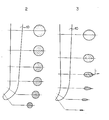
- laser light L goes through an optical fiber 51 and is fed into the probe 50, which is of long and narrow conical shape with a round fore end portion and whose outer surface is smooth.
- the laser light L passing through the probe 50 is reflected and refracted on an inner surface of the probe 50 to reach its tip end. Finally the laser light L is emitted only from the tip end concentratedly.
- a power density and its distribution diagram of laser light irradiation are shown as contour lines H and a curve Pd in Fig. 11 respectively. Accordingly, it is obvious that the laser light L is concentratedly emitted from the tip end of the probe 50. Therefore, while the thickness (depth) T1 of a coagulation layer C is increased, the laser light L is not irradiated effectively against tissues along the side of the probe, then the effect of an incision and hemostasis there is reduced.
- the inventor found that by forming a rough surface on a probe, the effective area of laser light irradiation can be extended, because laser light is refracted on the rough surface to be emitted in many directions.
- the inventor had done a lot of researches on these defects to find following things.
- the effect of an incision at a side part of an incised portion is enlarged by forming a rough surface on a probe and a surface layer having laser light scattering particles on the rough surface of the probe. Because, a scattering effect is enlarged by means of the light scattering particles in the surface layer as well as the rough surface of the probe.
- a broad area of the laser light irradiation can be obtained, while a depth T2 of a coagulation layer is reduced. Accordingly, the effect of the incision at the side part of the incised tissue is enlarged.
- the first defect relates to hemostasis. Since the power level of the laser light irradiation from the tip end is higher than that from the side of the probe, the coagulation layer in the tissues at the side part of the probe is not so deep. Therefore, the effect of the hemostasis directed by the depth of the coagulation is known to be reduced at the side part. If there is a blood vessel bv adjacent to the thin coagulation at the side part of the probe, there is a fear of bleeding there.
- the second defect relates to the process of the incision.
- the tissues are incised by the tip end of the probe. Therefore, it is comparatively easy for the probe to move on the surface of the tissues.
- a laser light emitting probe comprises longitudinally a base end on which laser light is impinged, a body through which the laser light is penetrated and a fore end portion from whose external surface the laser light is emitted, and the above mentioned fore end portion is covered with a light scattering surface and bends at a certain angle on a longitudinal cross section.
- a surface layer which contains laser light absorbing particles and laser light scattering particles having a larger refractive index than that of the material of the probe, is formed on the surface of at least from the bending part to the tip end of the bending fore end portion.
- a producing method of the laser light emitting probe comprises the steps of;
- the laser light can be irradiated with a broad effective area. Because, when the laser light is penetrated through the probe, the laser light is scattered at the surface of the probe. Therefore, the power level of the laser light emitted from the tip end of the probe is reduced while the power level of the laser light from the side surface of the probe is increased. Further, since the probe has the fore end portion, which bends at a certain angle on a longitudinal section, the power density distribution of the laser light is concentrated at the externally swelled side part of the bending fore end portion than at the inner side part thereof where there is a curvature center of bending.
- the laser light having a high power level is irradiated from the side surface of the probe against the tissues as shown in the power density distribution diagram of laser light irradiation of Fig. 4. Therefore, vaporization of the tissues, which are to be incised by the side of the probe, is accelerated, thus, the tissues can be incised easily. Further, as the depth of a coagulation layer caused by the incision is increased, even hemorrhagic tissue can be incised easily without much bleeding.
- a surface layer 5 can be formed on the surface of the transmissible member 1.
- the surface layer 5 contains light scattering particles 2, which are made of sapphire and the like and which have a larger refractive index than that of the transmissible member 1.
- the laser light L impinges on the light scattering particle 2 to be partially reflected on the surface of the light scattering particle 2, or to be partially penetrated into and emitted from the particle 2 with refraction. Therefore, the laser light L is emitted in various directions from the entire surface layer 5.
- the area of laser light irradiation can be extended to be larger than the area of laser light irradiation in case of forming the light scattering surface only by roughening.
- the surface layer 5 preferably contains laser light absorbing particles 3 made of carbon and the like.
- the greater part of the energy of the laser light L is converted to heat energy He by means of the laser light absorbing particles 3, and the tissues are heated by the heat energy He from the surface layer 5.
- the tissues can be incised with the laser light, which has low power level and which is penetrated into the transmissible member 1. Accordingly, when the tissues are incised, the transmissible member 1 can be moved rapidly. Further, the required energy of the laser light penetrating into the transmissible member 1 is low. As a result, the surgery can be carried out in short time, further with a cheap and small scaled laser light generator.
- the surface of the transmissible member 1 is roughened, then the above mentioned surface layer is formed on the rough surface to give a large effect of laser light scattering.
- the surface layer for example, if a dispersion containing the above mentioned laser light absorbing particles and the light scattering particles is coated on the surface of the transmissible member, after the vaporization of a dispersion medium, the contact of the probe having the surface layer with the tissue or other substances causes a damage to the surface layer. Because the both kinds of particles are attached to the surface of the transmissible member only by physical adsorptive power.
- the binder is preferably made of light transmissible material 4 such as quartz and the like to ensure the emission of the laser light from the surface layer 5.
- the laser light transmissible particles which have a melting point same as or lower than that of the transmissible member 1, are used as the transmissible material 4 and they are dispersed together with the absorbing particles and the light scattering particles in a proper liquid such as water.
- the transmissible member 1 painted with this dispersion is baked at a temperature which is higher than a melting point of the transmissible particle and within a limit as the transmissible member can keep its shape.
- the transmissible particles melt to form the surface layer of high mechanical strength together with the laser light absorbing particles and the light scattering particles. Therefore, the damages to the surface layer can be reduced because of its high strength.
- Fig. 1 is a longitudinal sectional view of a structure of a probe and a holding member therefor relating to the present invention
- Figs. 2 and 3 are schematic enlarged front views and enlarged sectional views of the important parts of laser light emitting probes relating to the present invention
- Fig. 4 is a schematic illustration showing an embodiment of a laser light emitting probe for a laser scalpel and a power density distribution diagram of laser light irradiation in this embodiment
- Figs. 5 and 6 are enlarged sectional views of surface layers
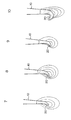
- Figs. 7, 8, 9 and 10 are power density distribution diagrams of laser light irradiation, where the fore end portion of each probe is bending at an each angle
- Fig. 1 is a longitudinal sectional view of a structure of a probe and a holding member therefor relating to the present invention
- Figs. 2 and 3 are schematic enlarged front views and enlarged sectional views of the important parts of laser light emitting probes relating to the present invention
- FIG. 11 is a schematic illustration showing a power density distribution diagram of laser light irradiation with a conventional probe
- Fig. 12 is a schematic illustration showing a power density distribution diagram of laser light irradiation with another conventional probe for comparing
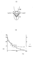
- Fig. 13 is a schematic illustration explaining an experiment
- Fig. 14 is a graph showing the result of the experiment of Fig. 13.
- Fig. 5 is an enlarged sectional view of a surface layer 5 formed on a probe 10, whose structure is shown in Fig. 1 as an embodiment.
- the surface layer 5 containing laser light scattering particles 2 and laser light absorbing particles 3 is formed with a laser light transmissible material 4 as a binder made from melted laser light transmissible particles as described before.
- FIG. 1 An example of the structure of the probe 10 and a holding member therefor is shown in Fig. 1.
- This probe 10 comprises a conically tapered inserting portion 30, a main holding portion 31, a flange 32 formed between them, and a bending fore end portion 20.
- the main holding portion 31 of the probe 10 is fitted in a cylindrical female connector 33 and fixed integrally thereto by caulking the mating portions 33a, by using a ceramic type adhesive between the mating surfaces or by the combination of these both means.
- the female connector 33 has, on the internal side surface thereof a female screw 34, which is adapted to mate removably with a male screw 36 of a male connector 35.
- the female connector 33 has holes 38 which facilitates the passage of cooling water W inside and outside thereof.
- the holes 38 are disposed adjacent to the top of a light receiving base 37 of the probe 10, for example, oppositely on a circumference of the female connector 33 although only one of them is shown in Fig. 1.
- the male connector 35 is pressed to be fitted into the end portion of a flexible tube jacket 39 fabricated of, for example, Teflon (the trademark for polytetrafluoroethylene).
- Teflon the trademark for polytetrafluoroethylene
- a laser light transmitting optical fiber 11 attached by an optical fiber 12 is inserted in the tube jacket 39 and the male connector 35. There is a gap 42 between the optical fiber 11 and the tube jacket 39 for passage of the cooling water.
- the stepped portion 40 has, for example, two slits 40a formed oppositely on a circumference of the stepped portion 40 for the cooling water W.
- the cooling water W is passed through the slits 40a and a passage 41 provided between the inner surface of the fore end portion of the male connector 35 and the outer surface of the transmitting optical fiber 11.
- a laser light emitting apparatus of this type described above is equipped in an endoscope and some other suitable holders while the female connector 33 is connected to mate with the male connector 35.
- the female connector 33 attached by the probe 10 is equipped directly in some suitable holders which already built in the transmitting optical fiber 11.
- a pulse laser light such as YAG and the like introduced through the optical fiber 12 is fed into the probe 10 from the light receiving base 37, therefore, is emitted mainly from all over the outer surface of the bending fore end portion 20.
- the cooling water W is fed through the gap 42, the slit 40a, the gap 41 to cool the probe 10, further, discharged through the opening 38 to flow out on the surface of tissues and then cool the tissues.
- the transmissible member of this invention is preferably fabricated from a natural or artificial ceramic material such as diamond, sapphire, quartz and the like due to their heat resistance.
- the light scattering particles relating to the present invention having a larger refractive index for the laser light than that of the transmissible member are of a natural or artificial material such as diamond, sapphire, quartz (a melting point is preferably high), single crystal zirconium oxide (Zr0 2 ), high melting point glass, ' transmissible and heat resistant synthetic resin, laser light reflective metal such as gold or aluminium, and a particle which is laser light reflective or non-reflective metal particle coated with laser reflective metal such as gold, aluminum and the like by means of the surface treatment such as plating.
- a natural or artificial material such as diamond, sapphire, quartz (a melting point is preferably high), single crystal zirconium oxide (Zr0 2 ), high melting point glass, ' transmissible and heat resistant synthetic resin, laser light reflective metal such as gold or aluminium, and a particle which is laser light reflective or non-reflective metal particle coated with laser reflective metal such as gold, aluminum and the like by means of the surface treatment such as plating.
- the laser transmissible material is preferably made of transmissible particle which can make a film when it melts, and more preferably has heat resistance, for example, a natural or artificial, sapphire, quartz, glass, transmissible and heat resistant synthetic resin and the like.
- a suitable transmissible material is selected from these materials in consideration of the relation to the material of the transmissible member.
- the laser light absorbing particle is made of carbon, graphite, iron oxide, manganese dioxide and the any other materials which can absorb the laser light to generate heat energy.
- a content of each particle in the surface layer(wt%) and each average particle size is preferably within ranges as shown in a following table. More preferable content and particle size are put in parentheses.
- the thickness of the surface layer is preferably 10 ⁇ m - 5mm, more preferably 30pm - lmm. If the surface layer having a desired thickness can not be formed by one cycle of the method, this cycle should be repeated until the surface having the desired thickness can be obtained.
- the surface layer is formed by following methods;
- the above mentioned three kinds of particles are dispersed in a dispersion medium, then it is heated to a temperature which is higher than the melting point of the transmissible particles, and the transmissible member is dipped in the dispersion.
- the dispersion dispersing the three kinds of particles can be painted to the transmissible member.
- this painting method facilitates the operation, because what should be done in this method is that only a part, which is desired to be covered with the surface layer, of the transmissible member, or preferably only a part, which is desired to be the bending fore end portion, is dipped in the dispersion and pulled up therefrom. Therefore this method is practical and rational.
- suitable liquid for example, water, alcohol or mixture of them can be used. Further sugar or starch is added to increase the viscosity of the dispersion medium.
- the present invention by forming the surface layer 5 on the surface of the transmissible member 1, the area of the laser light irradiation on the tissues is extended, because, the laser light is emitted widely in many directions from the surface layer 5 as shown in Fig. 4 and as described above.
- the inventor performed an experiment as follows, using a probe, whose fore end portion is not bending but straight as shown in Fig. 13;
- the contents of the light scattering particle, that of the transmissible particle, and that of the laser light absorbing particle will be referred as (A), (B) and (C) respectively.
- the inventor investigated each change of following two parameters against (C) under fixed condition of (A) : (B) 2 : 1.
- One investigated parameter is a laser light power level, with which an incision to a pig's liver can be started.
- Another parameter is a depth T of a coagulation layer Y below a carbonized layer X of treated tissues. Then, from the result in Fig. 14, following things are known.
- the incision can be started with the laser light having a low power level, then, it is possible for the probe to be moved quickly.
- the effect of hemostasis can be known by the depth d of the coagulation. Therefore, since the depth d is decreased, the hemostasis of the treated tissues is turned out to be reduced.
- the probe with high percentage of (C) in the surface layer can be used effectively for the incision to the tissues which bear the damage to some extent such as skin, fat layer and the like.
- the probe with low percentage of (C) can be used efficiently for an incision of the tissues, for which the hemostasis is regarded to be important.
- tissues are, for example, liver, heart and the like.
- the power level of the output from the laser light generator must be raised and the probe must be moved slowly.
- Equation (1) means that heat generation is progressed as (C) is increased. Accordingly, the incision is carried out by mainly vaporization. Therefore, since most of the incident laser energy is spent for the heating, the laser light can not penetrate so deeply into the tissues. As a result, the depth of the coagulation layer is reduced.
- Equation (2) means that the penetration of the laser light into the tissues is progressed as (C) is decreased. Therefore, the tissue absorbing laser light is heated, thus, the coagulation is made in the tissues.
- a suitable probe can be selected in accordance with a medical purpose, thereby a suitable treatment can be carried out easily.
- the probe must be covered with the light scattered surface, the surface layer is not necessary. That is to say, the probe may have only the rough surface as the scattering surface.
- the probe in the present invention must have the fore end portion, which bends at a certain angle on a longitudinal section.
- the meaning of "bending” includes the operation of making an angle straightly as well as the operation of making a curve.
- the power density distribution of the laser light irradiation varies with the change of a bending angle as shown in Figs. 7, 8, 9 and 10.
- the bending angle 6 shown in Fig. 1 is made by crossing the center line of a straight portion of the probe and a normal line. This normal line is perpendicular to the tangent line touching the externally swelled surface of the bending part of the fore end portion on the longitudinal section.
- the angle 8 is preferably larger than the critical angle of the material of the probe (the transmissible member) to the air to give a sufficient effect of the laser light scattering from the side surface of the probe.
- the bending fore end portion is preferably tapered.
- the laser light emitted from the circumference of the probe is substantially uniform.
- the externally swelled side of the bending fore end portion is tapered towards an external side (to the right or lower right on Fig. 3)
- the laser light emission toward the external side is increased.
- the incision is, thereby, carried out much easily.
- the probe which is sharp-edged towards the external side facilitates a mechanical incision as well as the incision with the laser light irradiation. As a result, the effect of the incision is significantly enlarged.
- a conically tapered probe is heated to a temperature higher than a softening temperature of the probe.
- the probe shows the above mentioned characteristics more clearly.
- the shape of the base portion of the probe in the present invention is not limited to the cylindrical shape in Figs. 1 and 4. It may be other shapes such as tapered cone, prism and the like.
- the probe of the present invention which is brought into contact with the living tissues, can be applied suitably for the incision, the vaporization and the coagulation of the living tissues, the thermal therapy and the like.
Abstract
Description
- This invention relates to a laser light emitting probe to permit an incision, vaporization of living tissues of an animal such as a human body, a thermal therapy and the like, and the producing method of the laser light emitting probe.
- In these days, medical treatments such as incisions of living tissues of animal organisms by irradiation with laser light are conspicuous due to its ability of hemostasis.
- It had been the conventional method that the laser light was irradiated from the fore end of an optical fiber which is brought out of contact with the living tissues. But this method causes severe damage to the fore end of the optical fiber. Therefore, a method which has been utilized lately is as follows;
- First, laser light is transmitted into an optical fiber, whose fore end portion locates adjacent to treated living tissues. Next, the laser light fed out from the optical fiber is fed into an emitting probe, which is brought into or out of contact with the living tissues. Then, the laser light is emitted from the surface of the probe to be irradiated against the living tissues. In this case, the probe should be brought into contact with the living tissues (hereafter "living tissue" is sometimes expressed by "tissue" only).
- On a medical treatment, if a probe is brought into contact with living tissues, there is an advantage that laser light can be irradiated against a precise position with small power loss comparing with a case, in which the probe is brought out of contact with the living tissues.
- Therefore, the inventor developed many kinds of contact probes which are utilized for various purposes. One embodiment is shown in Fig. 11. This probe is made of sapphire, quartz and the like. Usually, it has a smooth surface and is not provided with a surface layer. Further, it has a fore end portion of a uniformly ' tapered conical shape.
- Referring to Fig. 11, laser light L goes through an
optical fiber 51 and is fed into theprobe 50, which is of long and narrow conical shape with a round fore end portion and whose outer surface is smooth. The laser light L passing through theprobe 50 is reflected and refracted on an inner surface of theprobe 50 to reach its tip end. Finally the laser light L is emitted only from the tip end concentratedly. - In this case, a power density and its distribution diagram of laser light irradiation are shown as contour lines H and a curve Pd in Fig. 11 respectively. Accordingly, it is obvious that the laser light L is concentratedly emitted from the tip end of the
probe 50. Therefore, while the thickness (depth) T1 of a coagulation layer C is increased, the laser light L is not irradiated effectively against tissues along the side of the probe, then the effect of an incision and hemostasis there is reduced. - As a result, in case of the incision of hemorrhagic tissues such as liver and the like, the probe must be repeated to move along the same incision line little by little. Therefore, the surgery requires much labour and must be done carefully.
- Under these circumstances, the inventor found that by forming a rough surface on a probe, the effective area of laser light irradiation can be extended, because laser light is refracted on the rough surface to be emitted in many directions.
- Although it is possible to extend the effective area of the laser light irradiation by means of the above mentioned method, its effect is not sufficient. In order to compensate the low effect of an incision for tissues along the side of the probe, an output power ' level from a laser light generator should be enlarged. Further, the laser light having a high power level causes a severe damage to the tissues. Therefore, this probe is not applicable for the incision of hemorrhagic internal organs.
- The inventor had done a lot of researches on these defects to find following things.
- The effect of an incision at a side part of an incised portion is enlarged by forming a rough surface on a probe and a surface layer having laser light scattering particles on the rough surface of the probe. Because, a scattering effect is enlarged by means of the light scattering particles in the surface layer as well as the rough surface of the probe.
- Referring to Fig.12, by the
probe 50A having thesurface layer 50a, a broad area of the laser light irradiation can be obtained, while a depth T2 of a coagulation layer is reduced. Accordingly, the effect of the incision at the side part of the incised tissue is enlarged. - However, there are still some defects with the probe. The first defect relates to hemostasis. Since the power level of the laser light irradiation from the tip end is higher than that from the side of the probe, the coagulation layer in the tissues at the side part of the probe is not so deep. Therefore, the effect of the hemostasis directed by the depth of the coagulation is known to be reduced at the side part. If there is a blood vessel bv adjacent to the thin coagulation at the side part of the probe, there is a fear of bleeding there.
- The second defect relates to the process of the incision. When the probe starts to move along an incision line, the tissues are incised by the tip end of the probe. Therefore, it is comparatively easy for the probe to move on the surface of the tissues. However, there remains a difficulty of a probe-movement in the tissues at the side part of the probe. In other words, it is easy to start to incise, however, it is difficult to continue to incise along the incision line and since the probe moves too easily on the surface of the tissues, it is also difficult to know an incised depth in the tissues.
- On the other hand, such consideration for the hemostasis must not be taken for the incision of less hemorrhagic tissues such as skin, fat layer and the like. However, in order to compensate the reduced effect of the incision at the side part of the incised tissues, the laser light having a high power level is required. This causes a damage to the tissues. Further, this necessitates a high power and expensive laser light generator. If the power level remains a low level, the probe must be moved slowly, thus, it takes a long time to carry out a surgery with this probe.
- Therefore, it is a main object of the present invention to provide a laser light emitting probe permitting following things;
- laser light irradiation with a broad effective area;
- an effective incision by vaporization;
- an effective hemostasis at a side part of incised tissues;
- an incision for less-hemorrhagic tissues with a low power level of laser light irradiation; and
- an incision by quick and easy probe-movement for hemorrhagic tissues and also for the less-hemorrhagic tissues,
- and to provide a producing method of the above mentioned laser light emitting probe.
- According to the present invention, a laser light emitting probe comprises longitudinally a base end on which laser light is impinged, a body through which the laser light is penetrated and a fore end portion from whose external surface the laser light is emitted, and the above mentioned fore end portion is covered with a light scattering surface and bends at a certain angle on a longitudinal cross section.
- In the preferable embodiment of the present invention, a surface layer, which contains laser light absorbing particles and laser light scattering particles having a larger refractive index than that of the material of the probe, is formed on the surface of at least from the bending part to the tip end of the bending fore end portion.
- Further, according to the present invention, a producing method of the laser light emitting probe is provided. This method comprises the steps of;
- tapering a laser light transmissible member at least at its fore end portion;
- bending the fore end portion of the tapered transmissible member at a certain angle on a longitudinal cross section;
- making contact the bending transmissible member with a dispersion containing at least laser light absorbing particles, laser light scattering particles having a larger refractive index than that of the material of the transmissible member and laser light transmissible particles which have a melting point same as or lower than that of the transmissible member, and
- baking the contacted transmissible member with the dispersion ' at a temperature which is higher than the melting point of the laser light transmissible particles and within a limit as the transmissible member can keep its shape.
- According to the present invention, by forming a laser light scattering surface on the fore end portion of the probe, the laser light can be irradiated with a broad effective area. Because, when the laser light is penetrated through the probe, the laser light is scattered at the surface of the probe. Therefore, the power level of the laser light emitted from the tip end of the probe is reduced while the power level of the laser light from the side surface of the probe is increased. Further, since the probe has the fore end portion, which bends at a certain angle on a longitudinal section, the power density distribution of the laser light is concentrated at the externally swelled side part of the bending fore end portion than at the inner side part thereof where there is a curvature center of bending. Simultaneously, the laser light having a high power level is irradiated from the side surface of the probe against the tissues as shown in the power density distribution diagram of laser light irradiation of Fig. 4. Therefore, vaporization of the tissues, which are to be incised by the side of the probe, is accelerated, thus, the tissues can be incised easily. Further, as the depth of a coagulation layer caused by the incision is increased, even hemorrhagic tissue can be incised easily without much bleeding.
- As shown in Fig.5, in stead of forming a light scattering surface on a laser light
transmissible member 1 only by roughening, asurface layer 5 can be formed on the surface of thetransmissible member 1. In this case, thesurface layer 5 containslight scattering particles 2, which are made of sapphire and the like and which have a larger refractive index than that of thetransmissible member 1. When laser light L emitted from thetransmissible member 1 passes through thesurface layer 5, the laser light L impinges on thelight scattering particle 2 to be partially reflected on the surface of thelight scattering particle 2, or to be partially penetrated into and emitted from theparticle 2 with refraction. Therefore, the laser light L is emitted in various directions from theentire surface layer 5. As a result, by forming thesurface layer 5, the area of laser light irradiation can be extended to be larger than the area of laser light irradiation in case of forming the light scattering surface only by roughening. - Further, the
surface layer 5 preferably contains laserlight absorbing particles 3 made of carbon and the like. In this case, when the laser light L is impinged on the laserlight absorbing particles 3, the greater part of the energy of the laser light L is converted to heat energy He by means of the laserlight absorbing particles 3, and the tissues are heated by the heat energy He from thesurface layer 5. - Therefore, as the vaporization of the tissues is accelerated, the tissues can be incised with the laser light, which has low power level and which is penetrated into the
transmissible member 1. Accordingly, when the tissues are incised, thetransmissible member 1 can be moved rapidly. Further, the required energy of the laser light penetrating into thetransmissible member 1 is low. As a result, the surgery can be carried out in short time, further with a cheap and small scaled laser light generator. - Preferably, the surface of the
transmissible member 1 is roughened, then the above mentioned surface layer is formed on the rough surface to give a large effect of laser light scattering. - On the other hand, referring to the surface layer, for example, 'if a dispersion containing the above mentioned laser light absorbing particles and the light scattering particles is coated on the surface of the transmissible member, after the vaporization of a dispersion medium, the contact of the probe having the surface layer with the tissue or other substances causes a damage to the surface layer. Because the both kinds of particles are attached to the surface of the transmissible member only by physical adsorptive power.
- Therefore, by a binder which sticks the laser light absorbing particles and the light scattering particles to the surface of the transmissible member, adhesion of the surface layer to the transmissible member is enlarged.
- In this case, the binder is preferably made of light
transmissible material 4 such as quartz and the like to ensure the emission of the laser light from thesurface layer 5. The laser light transmissible particles, which have a melting point same as or lower than that of thetransmissible member 1, are used as thetransmissible material 4 and they are dispersed together with the absorbing particles and the light scattering particles in a proper liquid such as water. Then, thetransmissible member 1 painted with this dispersion is baked at a temperature which is higher than a melting point of the transmissible particle and within a limit as the transmissible member can keep its shape. As a result, the transmissible particles melt to form the surface layer of high mechanical strength together with the laser light absorbing particles and the light scattering particles. Therefore, the damages to the surface layer can be reduced because of its high strength. - Fig. 1 is a longitudinal sectional view of a structure of a probe and a holding member therefor relating to the present invention; Figs. 2 and 3 are schematic enlarged front views and enlarged sectional views of the important parts of laser light emitting probes relating to the present invention; Fig. 4 is a schematic illustration showing an embodiment of a laser light emitting probe for a laser scalpel and a power density distribution diagram of laser light irradiation in this embodiment; Figs. 5 and 6 are enlarged sectional views of surface layers; Figs. 7, 8, 9 and 10 are power density distribution diagrams of laser light irradiation, where the fore end portion of each probe is bending at an each angle; Fig. 11 is a schematic illustration showing a power density distribution diagram of laser light irradiation with a conventional probe; Fig. 12 is a schematic illustration showing a power density distribution diagram of laser light irradiation with another conventional probe for comparing; Fig. 13 is a schematic illustration explaining an experiment; Fig. 14 is a graph showing the result of the experiment of Fig. 13.
- Now, the present invention is described more particularly.
- Fig. 5 is an enlarged sectional view of a
surface layer 5 formed on aprobe 10, whose structure is shown in Fig. 1 as an embodiment. On thetransmissible member 1, thesurface layer 5 containing laserlight scattering particles 2 and laserlight absorbing particles 3 is formed with a laser lighttransmissible material 4 as a binder made from melted laser light transmissible particles as described before. - In this case, by forming a rough surface la on the
transmissible member 1, as shown in Fig. 6, a scattering effect of laser light irradiation is enlarged. - An example of the structure of the
probe 10 and a holding member therefor is shown in Fig. 1. Thisprobe 10 comprises a conically tapered insertingportion 30, a main holdingportion 31, aflange 32 formed between them, and a bendingfore end portion 20. Themain holding portion 31 of theprobe 10 is fitted in a cylindricalfemale connector 33 and fixed integrally thereto by caulking themating portions 33a, by using a ceramic type adhesive between the mating surfaces or by the combination of these both means. Thefemale connector 33 has, on the internal side surface thereof afemale screw 34, which is adapted to mate removably with amale screw 36 of amale connector 35. Thefemale connector 33 hasholes 38 which facilitates the passage of cooling water W inside and outside thereof. Theholes 38 are disposed adjacent to the top of alight receiving base 37 of theprobe 10, for example, oppositely on a circumference of thefemale connector 33 although only one of them is shown in Fig. 1. Then, themale connector 35 is pressed to be fitted into the end portion of aflexible tube jacket 39 fabricated of, for example, Teflon (the trademark for polytetrafluoroethylene). For this press fitting, themale connector 35 has steppedportions 40 at its base portion, and is firmly held so as not to be disengaged from thetube jacket 39. - A laser light transmitting
optical fiber 11 attached by anoptical fiber 12 is inserted in thetube jacket 39 and themale connector 35. There is agap 42 between theoptical fiber 11 and thetube jacket 39 for passage of the cooling water. Although the end portion of the transmittingoptical fiber 11 is closely fitted in themale connector 35 at its steppedportion 40, the steppedportion 40 has, for example, twoslits 40a formed oppositely on a circumference of the steppedportion 40 for the cooling water W. The cooling water W is passed through theslits 40a and apassage 41 provided between the inner surface of the fore end portion of themale connector 35 and the outer surface of the transmittingoptical fiber 11. - A laser light emitting apparatus of this type described above is equipped in an endoscope and some other suitable holders while the
female connector 33 is connected to mate with themale connector 35. Alternatively, thefemale connector 33 attached by theprobe 10 is equipped directly in some suitable holders which already built in the transmittingoptical fiber 11. - In this way, a pulse laser light such as YAG and the like introduced through the
optical fiber 12 is fed into theprobe 10 from thelight receiving base 37, therefore, is emitted mainly from all over the outer surface of the bendingfore end portion 20. At the same time, the cooling water W is fed through thegap 42, theslit 40a, thegap 41 to cool theprobe 10, further, discharged through theopening 38 to flow out on the surface of tissues and then cool the tissues. - The transmissible member of this invention is preferably fabricated from a natural or artificial ceramic material such as diamond, sapphire, quartz and the like due to their heat resistance.
- The light scattering particles relating to the present invention, having a larger refractive index for the laser light than that of the transmissible member are of a natural or artificial material such as diamond, sapphire, quartz (a melting point is preferably high), single crystal zirconium oxide (Zr02), high melting point glass, ' transmissible and heat resistant synthetic resin, laser light reflective metal such as gold or aluminium, and a particle which is laser light reflective or non-reflective metal particle coated with laser reflective metal such as gold, aluminum and the like by means of the surface treatment such as plating.
- The laser transmissible material is preferably made of transmissible particle which can make a film when it melts, and more preferably has heat resistance, for example, a natural or artificial, sapphire, quartz, glass, transmissible and heat resistant synthetic resin and the like. A suitable transmissible material is selected from these materials in consideration of the relation to the material of the transmissible member.
- The laser light absorbing particle is made of carbon, graphite, iron oxide, manganese dioxide and the any other materials which can absorb the laser light to generate heat energy.
- A content of each particle in the surface layer(wt%) and each average particle size is preferably within ranges as shown in a following table. More preferable content and particle size are put in parentheses.

- The thickness of the surface layer is preferably 10µm - 5mm, more preferably 30pm - lmm. If the surface layer having a desired thickness can not be formed by one cycle of the method, this cycle should be repeated until the surface having the desired thickness can be obtained. The surface layer is formed by following methods;
- The above mentioned three kinds of particles are dispersed in a dispersion medium, then it is heated to a temperature which is higher than the melting point of the transmissible particles, and the transmissible member is dipped in the dispersion.
- Alternatively the above mentioned three kinds of particles are melted to be sprayed to the transmissible member simultaneously.
- Further, other suitable methods for forming the surface layer can be used.
- By the above described first method, the dispersion dispersing the three kinds of particles can be painted to the transmissible member. Moreover, this painting method facilitates the operation, because what should be done in this method is that only a part, which is desired to be covered with the surface layer, of the transmissible member, or preferably only a part, which is desired to be the bending fore end portion, is dipped in the dispersion and pulled up therefrom. Therefore this method is practical and rational.
- As the dispersion medium, suitable liquid for example, water, alcohol or mixture of them can be used. Further sugar or starch is added to increase the viscosity of the dispersion medium.
- As described before, according to the present invention, by forming the
surface layer 5 on the surface of thetransmissible member 1, the area of the laser light irradiation on the tissues is extended, because, the laser light is emitted widely in many directions from thesurface layer 5 as shown in Fig. 4 and as described above. - On the other hand, the inventor performed an experiment as follows, using a probe, whose fore end portion is not bending but straight as shown in Fig. 13;
- In a following section, the contents of the light scattering particle, that of the transmissible particle, and that of the laser light absorbing particle will be referred as (A), (B) and (C) respectively. The inventor investigated each change of following two parameters against (C) under fixed condition of (A) : (B) = 2 : 1. One investigated parameter is a laser light power level, with which an incision to a pig's liver can be started. Another parameter is a depth T of a coagulation layer Y below a carbonized layer X of treated tissues. Then, from the result in Fig. 14, following things are known.
- When the percentage of (C) is high, the incision can be started with the laser light having a low power level, then, it is possible for the probe to be moved quickly. The effect of hemostasis can be known by the depth d of the coagulation. Therefore, since the depth d is decreased, the hemostasis of the treated tissues is turned out to be reduced. Finally, the probe with high percentage of (C) in the surface layer can be used effectively for the incision to the tissues which bear the damage to some extent such as skin, fat layer and the like.
- On the other hand, the probe with low percentage of (C) can be used efficiently for an incision of the tissues, for which the hemostasis is regarded to be important. Such tissues are, for example, liver, heart and the like. In this case, it is clear that the power level of the output from the laser light generator must be raised and the probe must be moved slowly.
- Referring to this experiment and the like, the inventor introduced these two equations, (1) and (2).


- Equation (1) means that heat generation is progressed as (C) is increased. Accordingly, the incision is carried out by mainly vaporization. Therefore, since most of the incident laser energy is spent for the heating, the laser light can not penetrate so deeply into the tissues. As a result, the depth of the coagulation layer is reduced.
- Equation (2) means that the penetration of the laser light into the tissues is progressed as (C) is decreased. Therefore, the tissue absorbing laser light is heated, thus, the coagulation is made in the tissues.
- Accordingly, if some kinds of probes, which differs in only percentage of (C) in the surface layers, are prepared in advance, a suitable probe can be selected in accordance with a medical purpose, thereby a suitable treatment can be carried out easily.
- In the present invention, although the probe must be covered with the light scattered surface, the surface layer is not necessary. That is to say, the probe may have only the rough surface as the scattering surface.
- However, the probe in the present invention must have the fore end portion, which bends at a certain angle on a longitudinal section. In this case, the meaning of "bending" includes the operation of making an angle straightly as well as the operation of making a curve.
- The power density distribution of the laser light irradiation varies with the change of a bending angle as shown in Figs. 7, 8, 9 and 10. When the bending angle is increased, the rate of the power level of laser light emission from the side surface of the probe is increased. In the present invention, the bending angle 6 shown in Fig. 1 is made by crossing the center line of a straight portion of the probe and a normal line. This normal line is perpendicular to the tangent line touching the externally swelled surface of the bending part of the fore end portion on the longitudinal section. The
angle 8 is preferably larger than the critical angle of the material of the probe (the transmissible member) to the air to give a sufficient effect of the laser light scattering from the side surface of the probe. - When the thickness of the bending fore end portion is uniform, the laser light emitted from the tip end is increased while that from the side surface of the probe is decreased. Therefore, the bending fore end portion is preferably tapered.
- If the cross section of the probe is circle as shown in Fig. 2, the laser light emitted from the circumference of the probe is substantially uniform. However, as shown in Fig. 3, if the externally swelled side of the bending fore end portion is tapered towards an external side (to the right or lower right on Fig. 3), the laser light emission toward the external side is increased. This is obvious from the illustration of a laser light course in Fig. 3. The incision is, thereby, carried out much easily. Moreover, the probe which is sharp-edged towards the external side facilitates a mechanical incision as well as the incision with the laser light irradiation. As a result, the effect of the incision is significantly enlarged.
- Now, an example of producing method for this probe is explained;
- First, a conically tapered probe is heated to a temperature higher than a softening temperature of the probe.
- Next, only the part of the fore end portion of the probe is bent at a certain angle on a longitudinal section.
- Finally, a part of an externally swelled side of the bending fore end portion is pressed from both before and back outer surfaces of the fore end portion so that the above mentioned probe can be formed.
- If the surface layer is formed on the surface of the probe having the bending fore end portion, the probe shows the above mentioned characteristics more clearly.
- The shape of the base portion of the probe in the present invention is not limited to the cylindrical shape in Figs. 1 and 4. It may be other shapes such as tapered cone, prism and the like.
- It is apparent from the foregoing explanation that the probe of the present invention, which is brought into contact with the living tissues, can be applied suitably for the incision, the vaporization and the coagulation of the living tissues, the thermal therapy and the like.
Claims (8)
Applications Claiming Priority (3)
| Application Number | Priority Date | Filing Date | Title |
|---|---|---|---|
| JP18273/89 | 1989-01-17 | ||
| JP1008273A JP2681073B2 (en) | 1989-01-17 | 1989-01-17 | Laser light emitting probe and manufacturing method thereof |
| PCT/JP1990/000040 WO1990007910A1 (en) | 1989-01-17 | 1990-01-17 | Laser beam emitting probe and method of manufacturing same |
Publications (3)
| Publication Number | Publication Date |
|---|---|
| EP0404968A1 true EP0404968A1 (en) | 1991-01-02 |
| EP0404968A4 EP0404968A4 (en) | 1991-06-19 |
| EP0404968B1 EP0404968B1 (en) | 1994-11-30 |
Family
ID=11688565
Family Applications (1)
| Application Number | Title | Priority Date | Filing Date |
|---|---|---|---|
| EP90901900A Expired - Lifetime EP0404968B1 (en) | 1989-01-17 | 1990-01-17 | Laser beam emitting probe and method of manufacturing same |
Country Status (11)
| Country | Link |
|---|---|
| US (1) | US5139495A (en) |
| EP (1) | EP0404968B1 (en) |
| JP (1) | JP2681073B2 (en) |
| KR (1) | KR910700027A (en) |
| CN (1) | CN1044218A (en) |
| AT (1) | ATE114440T1 (en) |
| AU (1) | AU4949190A (en) |
| CA (1) | CA2025351A1 (en) |
| DE (1) | DE69014438T2 (en) |
| WO (1) | WO1990007910A1 (en) |
| ZA (1) | ZA90288B (en) |
Cited By (6)
| Publication number | Priority date | Publication date | Assignee | Title |
|---|---|---|---|---|
| EP0441974A1 (en) * | 1989-09-05 | 1991-08-21 | S.L.T. Japan Co, Ltd. | Device for irradiating laser beams |
| WO1999059483A1 (en) * | 1998-05-18 | 1999-11-25 | Dornier Medtech Holding International Gmbh | Laser instrument |
| US7503701B2 (en) | 2005-04-18 | 2009-03-17 | Dornier Medtech Laser Gmbh | Systems and methods for cleaning an optical fibre |
| WO2011161126A1 (en) | 2010-06-21 | 2011-12-29 | Clinical Laserthermia Systems Ab | A system for providing insertable probes |
| US8114068B2 (en) | 2006-10-17 | 2012-02-14 | Dornier Medtech Laser Gmbh | Light guide |
| US9149334B2 (en) | 2008-04-25 | 2015-10-06 | Dornier Medtech Laser Gmbh | Light-based method for the endovascular treatment of pathologically altered blood vessels |
Families Citing this family (73)
| Publication number | Priority date | Publication date | Assignee | Title |
|---|---|---|---|---|
| JP3148216B2 (en) * | 1990-01-22 | 2001-03-19 | 株式会社エス・エル・ティ・ジャパン | Treatment equipment by laser beam irradiation |
| EP0680283B1 (en) * | 1992-04-24 | 1998-05-13 | Surgical Laser Technologies | Thermally-resistant medical probe |
| DE69229128T2 (en) * | 1992-04-24 | 2000-02-24 | Surgical Laser Tech | MEDICAL DEVICE |
| US5342355A (en) * | 1992-10-19 | 1994-08-30 | Laser Centers Of America | Energy delivering cap element for end of optic fiber conveying laser energy |
| JP2704601B2 (en) * | 1993-04-12 | 1998-01-26 | セイコーインスツルメンツ株式会社 | Scanning near-field atomic force microscope, probe used in the microscope, and method of manufacturing the probe |
| JPH07163578A (en) * | 1993-04-29 | 1995-06-27 | S L T Japan:Kk | Irradiation device for laser beam |
| IL105956A (en) * | 1993-06-08 | 1996-10-16 | Univ Ramot | Laser beam waveguide and laser beam delivery system including same |
| US5416878A (en) * | 1993-07-29 | 1995-05-16 | Endeavor Surgical Products, Inc. | Surgical methods and apparatus using a bent-tip side-firing laser fiber |
| US5599342A (en) * | 1995-01-27 | 1997-02-04 | Candela Laser Corporation | Method for treating pigmentation abnormalities using pulsed laser radiation with an elongated cross-section and apparatus for providing same |
| AU718841B2 (en) * | 1995-10-31 | 2000-04-20 | Indigo Medical, Incorporated | Light-diffusing device for an optical fiber, methods of producing and using same, and apparatus for diffusing light from an optical fiber |
| US5879346A (en) * | 1995-12-18 | 1999-03-09 | Esc Medical Systems, Ltd. | Hair removal by selective photothermolysis with an alexandrite laser |
| GB2308307A (en) * | 1995-12-18 | 1997-06-25 | Laser Ind Ltd | Depilating laser |
| DE19636265B4 (en) * | 1996-09-06 | 2007-09-20 | Kaltenbach & Voigt Gmbh | laser instrument |
| US5810801A (en) * | 1997-02-05 | 1998-09-22 | Candela Corporation | Method and apparatus for treating wrinkles in skin using radiation |
| US6200134B1 (en) | 1998-01-20 | 2001-03-13 | Kerr Corporation | Apparatus and method for curing materials with radiation |
| US6208788B1 (en) * | 1998-07-29 | 2001-03-27 | Ultradent Products, Inc. | Apparatus and methods for concentrating light through fiber optic funnels coupled to dental light guides |
| US6126655A (en) | 1998-08-11 | 2000-10-03 | The General Hospital Corporation | Apparatus and method for selective laser-induced heating of biological tissue |
| US6396613B1 (en) * | 1998-12-22 | 2002-05-28 | General Electric Company | Optical high speed communications for a computed tomography x-ray machine |
| US6974319B2 (en) * | 1999-09-24 | 2005-12-13 | Cao Group, Inc. | Curing light |
| US6780010B2 (en) | 1999-09-24 | 2004-08-24 | Cao Group, Inc. | Curing light |
| US6926524B2 (en) * | 1999-09-24 | 2005-08-09 | Cao Group, Inc. | Curing light |
| US6929472B2 (en) | 1999-09-24 | 2005-08-16 | Cao Group, Inc. | Curing light |
| US6719558B2 (en) | 1999-09-24 | 2004-04-13 | Densen Cao | Curing light |
| US6988891B2 (en) * | 1999-09-24 | 2006-01-24 | Cao Group, Inc. | Curing light |
| US7066732B2 (en) * | 1999-09-24 | 2006-06-27 | Cao Group, Inc. | Method for curing light-curable materials |
| US6719559B2 (en) | 1999-09-24 | 2004-04-13 | Densen Cao | Curing light |
| US6981867B2 (en) | 1999-09-24 | 2006-01-03 | Cao Group, Inc. | Curing light |
| US7077648B2 (en) * | 1999-09-24 | 2006-07-18 | Cao Group, Inc. | Curing light |
| US6755649B2 (en) | 1999-09-24 | 2004-06-29 | Cao Group, Inc. | Curing light |
| US6953340B2 (en) * | 1999-09-24 | 2005-10-11 | Cao Group, Inc. | Light for use in activating light-activated materials, the light having a detachable light module containing a heat sink and a semiconductor chip |
| US6824294B2 (en) * | 1999-09-24 | 2004-11-30 | Cao Group, Inc. | Light for use in activating light-activated materials, the light having a plurality of chips mounted in a gross well of a heat sink, and a dome covering the chips |
| US6979193B2 (en) | 1999-09-24 | 2005-12-27 | Cao Group, Inc. | Curing light |
| US6971875B2 (en) | 1999-09-24 | 2005-12-06 | Cao Group, Inc. | Dental curing light |
| US6910886B2 (en) | 1999-09-24 | 2005-06-28 | Cao Group, Inc. | Curing light |
| US6988890B2 (en) | 1999-09-24 | 2006-01-24 | Cao Group, Inc. | Curing light |
| US6755648B2 (en) | 1999-09-24 | 2004-06-29 | Cao Group, Inc. | Curing light |
| US6971876B2 (en) | 1999-09-24 | 2005-12-06 | Cao Group, Inc. | Curing light |
| US7294364B2 (en) * | 1999-09-24 | 2007-11-13 | Cao Group, Inc. | Method for curing composite materials |
| US6932600B2 (en) * | 1999-09-24 | 2005-08-23 | Cao Group, Inc. | Curing light |
| US6464693B1 (en) * | 2000-03-06 | 2002-10-15 | Plc Medical Systems, Inc. | Myocardial revascularization |
| US7108504B2 (en) | 2001-07-10 | 2006-09-19 | Cao Group, Inc. | Light for use in activating light-activated materials, the light having insulators and an air jacket |
| US6799967B2 (en) | 2001-07-10 | 2004-10-05 | Cao Group, Inc. | Light for use in activating light-activated materials, the light having a plurality of light emitting single chip arrays |
| US7106523B2 (en) | 2002-01-11 | 2006-09-12 | Ultradent Products, Inc. | Optical lens used to focus led light |
| US6940659B2 (en) | 2002-01-11 | 2005-09-06 | Ultradent Products, Inc. | Cone-shaped lens having increased forward light intensity and kits incorporating such lenses |
| US6702576B2 (en) | 2002-02-22 | 2004-03-09 | Ultradent Products, Inc. | Light-curing device with detachably interconnecting light applicator |
| DE10245140B4 (en) * | 2002-09-27 | 2005-10-20 | Dornier Medtech Laser Gmbh | Intelligent therapy fiber |
| US20040101802A1 (en) * | 2002-11-21 | 2004-05-27 | Scott Robert R. | Wide bandwidth led curing light |
| US6890175B2 (en) * | 2002-12-18 | 2005-05-10 | Ultradent Products, Inc. | Cooling system for hand-held curing light |
| US6994546B2 (en) * | 2002-12-18 | 2006-02-07 | Ultradent Products, Inc. | Light curing device with detachable power supply |
| US20070020578A1 (en) * | 2005-07-19 | 2007-01-25 | Scott Robert R | Dental curing light having a short wavelength LED and a fluorescing lens for converting wavelength light to curing wavelengths and related method |
| US20040214131A1 (en) * | 2003-04-25 | 2004-10-28 | Ultradent Products, Inc., | Spot curing lens used to spot cure a dental appliance adhesive and systems and methods employing such lenses |
| US7192276B2 (en) | 2003-08-20 | 2007-03-20 | Ultradent Products, Inc. | Dental curing light adapted to emit light at a desired angle |
| US7144250B2 (en) | 2003-12-17 | 2006-12-05 | Ultradent Products, Inc. | Rechargeable dental curing light |
| US7195482B2 (en) | 2003-12-30 | 2007-03-27 | Ultradent Products, Inc. | Dental curing device having a heat sink for dissipating heat |
| US7074040B2 (en) | 2004-03-30 | 2006-07-11 | Ultradent Products, Inc. | Ball lens for use with a dental curing light |
| DE102005038611B4 (en) | 2004-08-16 | 2023-01-12 | Iridex Corp. | Directional probe treatment device for treatment of an eye |
| US7056116B2 (en) | 2004-10-26 | 2006-06-06 | Ultradent Products, Inc. | Heat sink for dental curing light comprising a plurality of different materials |
| US8277495B2 (en) | 2005-01-13 | 2012-10-02 | Candela Corporation | Method and apparatus for treating a diseased nail |
| WO2006076759A1 (en) * | 2005-01-21 | 2006-07-27 | Optiscan Pty Ltd | Fibre bundle for contact endomicroscopy |
| EP2796168B1 (en) | 2005-09-28 | 2017-09-06 | Candela Corporation | Treating cellulite |
| US20070128577A1 (en) * | 2005-12-05 | 2007-06-07 | Ultradent Products, Inc. | Dental curing lights including a capacitor power source |
| US7891362B2 (en) | 2005-12-23 | 2011-02-22 | Candela Corporation | Methods for treating pigmentary and vascular abnormalities in a dermal region |
| US8246611B2 (en) | 2006-06-14 | 2012-08-21 | Candela Corporation | Treatment of skin by spatial modulation of thermal heating |
| US9066777B2 (en) | 2009-04-02 | 2015-06-30 | Kerr Corporation | Curing light device |
| US9072572B2 (en) | 2009-04-02 | 2015-07-07 | Kerr Corporation | Dental light device |
| JP5059074B2 (en) | 2009-09-18 | 2012-10-24 | 株式会社モリタ製作所 | Dental laser irradiation tip |
| US8939766B2 (en) * | 2010-04-19 | 2015-01-27 | Alan Wong | Dental tools for photo-curing of dental fillings |
| US20120290047A1 (en) * | 2011-05-11 | 2012-11-15 | John Hendy | System and method for delivering laser energy to the body |
| US9763692B2 (en) | 2012-09-14 | 2017-09-19 | The Spectranetics Corporation | Tissue slitting methods and systems |
| WO2014058220A2 (en) * | 2012-10-08 | 2014-04-17 | (주)루트로닉 | Laser surgical instrument for spine surgery and method thereof |
| US10039932B2 (en) * | 2012-11-20 | 2018-08-07 | Biolase, Inc. | Eyelid treatment device |
| US10835279B2 (en) | 2013-03-14 | 2020-11-17 | Spectranetics Llc | Distal end supported tissue slitting apparatus |
| EP3117250A4 (en) * | 2014-03-14 | 2017-10-04 | AFL Telecommunications LLC | Method for making bent tip fibers |
Citations (4)
| Publication number | Priority date | Publication date | Assignee | Title |
|---|---|---|---|---|
| US4273127A (en) * | 1978-10-12 | 1981-06-16 | Research Corporation | Method for cutting and coagulating tissue |
| WO1985005262A1 (en) * | 1984-05-22 | 1985-12-05 | Surgical Laser Technologies Ohio, Inc. | Medical and surgical laser probe i |
| JPS6360412A (en) * | 1986-09-01 | 1988-03-16 | Nippon Telegr & Teleph Corp <Ntt> | Method for making light incident upon side of optical fiber and method for photodetecting light radiated from side of optical fiber |
| EP0408757A1 (en) * | 1988-12-12 | 1991-01-23 | S.L.T. Japan Co, Ltd. | Laser beam transmitting member and method of manufacturing the same |
Family Cites Families (20)
| Publication number | Priority date | Publication date | Assignee | Title |
|---|---|---|---|---|
| US2056990A (en) * | 1934-10-13 | 1936-10-13 | Cleon W Symonds | Ultraviolet ray instrument |
| US2186143A (en) * | 1939-03-09 | 1940-01-09 | Edwin A Neugass | Illuminator |
| US3834391A (en) * | 1973-01-19 | 1974-09-10 | Block Carol Ltd | Method and apparatus for photoepilation |
| GB1485908A (en) * | 1974-05-21 | 1977-09-14 | Nath G | Apparatus for applying light radiation |
| US4126136A (en) * | 1976-02-09 | 1978-11-21 | Research Corporation | Photocoagulating scalpel system |
| US4693244A (en) * | 1984-05-22 | 1987-09-15 | Surgical Laser Technologies, Inc. | Medical and surgical laser probe I |
| JPH0741082B2 (en) * | 1984-09-14 | 1995-05-10 | オリンパス光学工業株式会社 | Laser probe |
| US4848339A (en) * | 1984-09-17 | 1989-07-18 | Xintec Corporation | Laser heated intravascular cautery cap assembly |
| US4994060A (en) * | 1984-09-17 | 1991-02-19 | Xintec Corporation | Laser heated cautery cap with transparent substrate |
| US4799479A (en) * | 1984-10-24 | 1989-01-24 | The Beth Israel Hospital Association | Method and apparatus for angioplasty |
| US4693556A (en) * | 1985-06-04 | 1987-09-15 | Laser Therapeutics, Inc. | Apparatus for producing a spherical pattern of light and method of manufacture |
| JPS62161382A (en) * | 1986-01-13 | 1987-07-17 | 森 敬 | Light irradiating remedy cloth |
| JPH039687Y2 (en) * | 1986-04-01 | 1991-03-11 | ||
| US4736743A (en) * | 1986-05-12 | 1988-04-12 | Surgical Laser Technology, Inc. | Vaporization contact laser probe |
| US4860743A (en) * | 1986-10-27 | 1989-08-29 | University Of Florida | Laser method and apparatus for the recanalization of vessels and the treatment of other cardiac conditions |
| JPS63130060A (en) * | 1986-11-21 | 1988-06-02 | 星野 雅彦 | Production of laser knife |
| JPH0712363B2 (en) * | 1987-02-16 | 1995-02-15 | 株式会社モリタ製作所 | Special laser chip |
| JPS63216579A (en) * | 1987-03-05 | 1988-09-08 | 大工園 則雄 | Laser beam irradiation apparatus for hyperthermia |
| JP2753578B2 (en) * | 1987-06-22 | 1998-05-20 | サージカル・レーザー・テクノロジーズ・インコーポレーテット | Medical laser probe |
| US4878492A (en) * | 1987-10-08 | 1989-11-07 | C. R. Bard, Inc. | Laser balloon catheter |
-
1989
- 1989-01-17 JP JP1008273A patent/JP2681073B2/en not_active Expired - Fee Related
-
1990
- 1990-01-12 US US07/464,113 patent/US5139495A/en not_active Expired - Fee Related
- 1990-01-16 ZA ZA90288A patent/ZA90288B/en unknown
- 1990-01-17 EP EP90901900A patent/EP0404968B1/en not_active Expired - Lifetime
- 1990-01-17 KR KR1019900702050A patent/KR910700027A/en not_active Application Discontinuation
- 1990-01-17 AT AT90901900T patent/ATE114440T1/en not_active IP Right Cessation
- 1990-01-17 AU AU49491/90A patent/AU4949190A/en not_active Abandoned
- 1990-01-17 DE DE69014438T patent/DE69014438T2/en not_active Expired - Fee Related
- 1990-01-17 WO PCT/JP1990/000040 patent/WO1990007910A1/en active IP Right Grant
- 1990-01-17 CN CN90100247A patent/CN1044218A/en active Pending
- 1990-01-17 CA CA002025351A patent/CA2025351A1/en not_active Abandoned
Patent Citations (4)
| Publication number | Priority date | Publication date | Assignee | Title |
|---|---|---|---|---|
| US4273127A (en) * | 1978-10-12 | 1981-06-16 | Research Corporation | Method for cutting and coagulating tissue |
| WO1985005262A1 (en) * | 1984-05-22 | 1985-12-05 | Surgical Laser Technologies Ohio, Inc. | Medical and surgical laser probe i |
| JPS6360412A (en) * | 1986-09-01 | 1988-03-16 | Nippon Telegr & Teleph Corp <Ntt> | Method for making light incident upon side of optical fiber and method for photodetecting light radiated from side of optical fiber |
| EP0408757A1 (en) * | 1988-12-12 | 1991-01-23 | S.L.T. Japan Co, Ltd. | Laser beam transmitting member and method of manufacturing the same |
Non-Patent Citations (2)
| Title |
|---|
| PATENT ABSTRACTS OF JAPAN, vol. 12, no. 280 (P-739)[3127], 2nd August 1988; & JP-A-63 60 412 (NIPPON TELEGR. & TELEPH. CORP.) 16-03-1988 * |
| See also references of WO9007910A1 * |
Cited By (9)
| Publication number | Priority date | Publication date | Assignee | Title |
|---|---|---|---|---|
| EP0441974A1 (en) * | 1989-09-05 | 1991-08-21 | S.L.T. Japan Co, Ltd. | Device for irradiating laser beams |
| EP0441974B1 (en) * | 1989-09-05 | 1995-05-24 | S.L.T. Japan Co, Ltd. | Device for irradiating laser beams |
| WO1999059483A1 (en) * | 1998-05-18 | 1999-11-25 | Dornier Medtech Holding International Gmbh | Laser instrument |
| US6699239B1 (en) | 1998-05-18 | 2004-03-02 | Dornier Medtech Systems Gmbh | Laser instrument |
| US7503701B2 (en) | 2005-04-18 | 2009-03-17 | Dornier Medtech Laser Gmbh | Systems and methods for cleaning an optical fibre |
| US8114068B2 (en) | 2006-10-17 | 2012-02-14 | Dornier Medtech Laser Gmbh | Light guide |
| US9149334B2 (en) | 2008-04-25 | 2015-10-06 | Dornier Medtech Laser Gmbh | Light-based method for the endovascular treatment of pathologically altered blood vessels |
| US9168098B2 (en) | 2008-04-25 | 2015-10-27 | Dornier Medtech Laser Gmbh | Light-based method for the endovascular treatment of pathologically altered blood vessels |
| WO2011161126A1 (en) | 2010-06-21 | 2011-12-29 | Clinical Laserthermia Systems Ab | A system for providing insertable probes |
Also Published As
| Publication number | Publication date |
|---|---|
| EP0404968A4 (en) | 1991-06-19 |
| DE69014438D1 (en) | 1995-01-12 |
| KR910700027A (en) | 1991-03-13 |
| WO1990007910A1 (en) | 1990-07-26 |
| EP0404968B1 (en) | 1994-11-30 |
| ATE114440T1 (en) | 1994-12-15 |
| CA2025351A1 (en) | 1990-07-18 |
| CN1044218A (en) | 1990-08-01 |
| ZA90288B (en) | 1990-10-31 |
| DE69014438T2 (en) | 1995-05-24 |
| JPH02189142A (en) | 1990-07-25 |
| US5139495A (en) | 1992-08-18 |
| JP2681073B2 (en) | 1997-11-19 |
| AU4949190A (en) | 1990-08-13 |
Similar Documents
| Publication | Publication Date | Title |
|---|---|---|
| EP0404968A1 (en) | Laser beam emitting probe and method of manufacturing same | |
| EP0433464B1 (en) | Laser guide probe | |
| EP0422233B1 (en) | Laser beam emitter | |
| CA2049013C (en) | Laser light irradiation apparatus for medical treatment | |
| US4693244A (en) | Medical and surgical laser probe I | |
| US5290280A (en) | Laser light irradiation apparatus | |
| US6942657B2 (en) | Intralumenal contact sensor | |
| EP0408757A1 (en) | Laser beam transmitting member and method of manufacturing the same | |
| WO2001013812A1 (en) | Maneuverable optical fiber device for cardiac photoablation | |
| JPS61502169A (en) | Medical and surgical laser probes | |
| EP0424272A2 (en) | Laser light irradiation apparatus | |
| JPH0747082A (en) | Laser probe for operation | |
| JPS62194869A (en) | Fiber probe | |
| Verdaasdonck et al. | Optical characteristics of sapphire laser scalpels analysed by ray-tracing |
Legal Events
| Date | Code | Title | Description |
|---|---|---|---|
| PUAI | Public reference made under article 153(3) epc to a published international application that has entered the european phase |
Free format text: ORIGINAL CODE: 0009012 |
|
| AK | Designated contracting states |
Kind code of ref document: A1 Designated state(s): AT CH DE ES FR GB IT LI NL SE |
|
| 17P | Request for examination filed |
Effective date: 19901228 |
|
| A4 | Supplementary search report drawn up and despatched |
Effective date: 19910426 |
|
| AK | Designated contracting states |
Kind code of ref document: A4 Designated state(s): AT CH DE ES FR GB IT LI NL SE |
|
| 17Q | First examination report despatched |
Effective date: 19930630 |
|
| GRAA | (expected) grant |
Free format text: ORIGINAL CODE: 0009210 |
|
| AK | Designated contracting states |
Kind code of ref document: B1 Designated state(s): AT CH DE ES FR GB IT LI NL SE |
|
| PG25 | Lapsed in a contracting state [announced via postgrant information from national office to epo] |
Ref country code: NL Effective date: 19941130 Ref country code: ES Free format text: THE PATENT HAS BEEN ANNULLED BY A DECISION OF A NATIONAL AUTHORITY Effective date: 19941130 |
|
| REF | Corresponds to: |
Ref document number: 114440 Country of ref document: AT Date of ref document: 19941215 Kind code of ref document: T |
|
| REF | Corresponds to: |
Ref document number: 69014438 Country of ref document: DE Date of ref document: 19950112 |
|
| ITF | It: translation for a ep patent filed |
Owner name: STUDIO TORTA SOCIETA' SEMPLICE |
|
| ET | Fr: translation filed | ||
| PG25 | Lapsed in a contracting state [announced via postgrant information from national office to epo] |
Ref country code: SE Effective date: 19950228 |
|
| NLV1 | Nl: lapsed or annulled due to failure to fulfill the requirements of art. 29p and 29m of the patents act | ||
| PLBE | No opposition filed within time limit |
Free format text: ORIGINAL CODE: 0009261 |
|
| STAA | Information on the status of an ep patent application or granted ep patent |
Free format text: STATUS: NO OPPOSITION FILED WITHIN TIME LIMIT |
|
| 26N | No opposition filed | ||
| PGFP | Annual fee paid to national office [announced via postgrant information from national office to epo] |
Ref country code: FR Payment date: 19951220 Year of fee payment: 7 |
|
| PGFP | Annual fee paid to national office [announced via postgrant information from national office to epo] |
Ref country code: AT Payment date: 19951225 Year of fee payment: 7 |
|
| PGFP | Annual fee paid to national office [announced via postgrant information from national office to epo] |
Ref country code: GB Payment date: 19960112 Year of fee payment: 7 |
|
| PGFP | Annual fee paid to national office [announced via postgrant information from national office to epo] |
Ref country code: DE Payment date: 19960120 Year of fee payment: 7 |
|
| PGFP | Annual fee paid to national office [announced via postgrant information from national office to epo] |
Ref country code: CH Payment date: 19960126 Year of fee payment: 7 |
|
| PG25 | Lapsed in a contracting state [announced via postgrant information from national office to epo] |
Ref country code: GB Effective date: 19970117 Ref country code: AT Effective date: 19970117 |
|
| PG25 | Lapsed in a contracting state [announced via postgrant information from national office to epo] |
Ref country code: LI Effective date: 19970131 Ref country code: CH Effective date: 19970131 |
|
| GBPC | Gb: european patent ceased through non-payment of renewal fee |
Effective date: 19970117 |
|
| REG | Reference to a national code |
Ref country code: CH Ref legal event code: PL |
|
| PG25 | Lapsed in a contracting state [announced via postgrant information from national office to epo] |
Ref country code: FR Effective date: 19970930 |
|
| PG25 | Lapsed in a contracting state [announced via postgrant information from national office to epo] |
Ref country code: DE Effective date: 19971001 |
|
| REG | Reference to a national code |
Ref country code: FR Ref legal event code: ST |
|
| PG25 | Lapsed in a contracting state [announced via postgrant information from national office to epo] |
Ref country code: IT Free format text: LAPSE BECAUSE OF NON-PAYMENT OF DUE FEES Effective date: 20050117 |