EP0400770A2 - Measuring the strength of a material within a moving web - Google Patents
Measuring the strength of a material within a moving web Download PDFInfo
- Publication number
- EP0400770A2 EP0400770A2 EP90300436A EP90300436A EP0400770A2 EP 0400770 A2 EP0400770 A2 EP 0400770A2 EP 90300436 A EP90300436 A EP 90300436A EP 90300436 A EP90300436 A EP 90300436A EP 0400770 A2 EP0400770 A2 EP 0400770A2
- Authority
- EP
- European Patent Office
- Prior art keywords
- ultrasonic wave
- strength
- web
- light beam
- laser
- Prior art date
- Legal status (The legal status is an assumption and is not a legal conclusion. Google has not performed a legal analysis and makes no representation as to the accuracy of the status listed.)
- Granted
Links
Images

Classifications
-
- G—PHYSICS
- G01—MEASURING; TESTING
- G01N—INVESTIGATING OR ANALYSING MATERIALS BY DETERMINING THEIR CHEMICAL OR PHYSICAL PROPERTIES
- G01N29/00—Investigating or analysing materials by the use of ultrasonic, sonic or infrasonic waves; Visualisation of the interior of objects by transmitting ultrasonic or sonic waves through the object
- G01N29/34—Generating the ultrasonic, sonic or infrasonic waves, e.g. electronic circuits specially adapted therefor
- G01N29/341—Generating the ultrasonic, sonic or infrasonic waves, e.g. electronic circuits specially adapted therefor with time characteristics
- G01N29/343—Generating the ultrasonic, sonic or infrasonic waves, e.g. electronic circuits specially adapted therefor with time characteristics pulse waves, e.g. particular sequence of pulses, bursts
-
- G—PHYSICS
- G01—MEASURING; TESTING
- G01N—INVESTIGATING OR ANALYSING MATERIALS BY DETERMINING THEIR CHEMICAL OR PHYSICAL PROPERTIES
- G01N29/00—Investigating or analysing materials by the use of ultrasonic, sonic or infrasonic waves; Visualisation of the interior of objects by transmitting ultrasonic or sonic waves through the object
- G01N29/04—Analysing solids
- G01N29/07—Analysing solids by measuring propagation velocity or propagation time of acoustic waves
-
- G—PHYSICS
- G01—MEASURING; TESTING
- G01N—INVESTIGATING OR ANALYSING MATERIALS BY DETERMINING THEIR CHEMICAL OR PHYSICAL PROPERTIES
- G01N29/00—Investigating or analysing materials by the use of ultrasonic, sonic or infrasonic waves; Visualisation of the interior of objects by transmitting ultrasonic or sonic waves through the object
- G01N29/22—Details, e.g. general constructional or apparatus details
- G01N29/24—Probes
- G01N29/2418—Probes using optoacoustic interaction with the material, e.g. laser radiation, photoacoustics
-
- G—PHYSICS
- G01—MEASURING; TESTING
- G01N—INVESTIGATING OR ANALYSING MATERIALS BY DETERMINING THEIR CHEMICAL OR PHYSICAL PROPERTIES
- G01N29/00—Investigating or analysing materials by the use of ultrasonic, sonic or infrasonic waves; Visualisation of the interior of objects by transmitting ultrasonic or sonic waves through the object
- G01N29/34—Generating the ultrasonic, sonic or infrasonic waves, e.g. electronic circuits specially adapted therefor
- G01N29/341—Generating the ultrasonic, sonic or infrasonic waves, e.g. electronic circuits specially adapted therefor with time characteristics
- G01N29/345—Generating the ultrasonic, sonic or infrasonic waves, e.g. electronic circuits specially adapted therefor with time characteristics continuous waves
-
- G—PHYSICS
- G01—MEASURING; TESTING
- G01N—INVESTIGATING OR ANALYSING MATERIALS BY DETERMINING THEIR CHEMICAL OR PHYSICAL PROPERTIES
- G01N33/00—Investigating or analysing materials by specific methods not covered by groups G01N1/00 - G01N31/00
- G01N33/36—Textiles
- G01N33/367—Fabric or woven textiles
-
- G—PHYSICS
- G01—MEASURING; TESTING
- G01N—INVESTIGATING OR ANALYSING MATERIALS BY DETERMINING THEIR CHEMICAL OR PHYSICAL PROPERTIES
- G01N2291/00—Indexing codes associated with group G01N29/00
- G01N2291/02—Indexing codes associated with the analysed material
- G01N2291/023—Solids
- G01N2291/0237—Thin materials, e.g. paper, membranes, thin films
Definitions
- This invention relates to measuring the strength of material within a web.
- Photoacoustic interaction has been used to induce ultrasonic waves into a continuous, fast moving web of paper.
- US Patent No. US-A-674 332 Patent No. US-A-674 332 (Pace et al) discloses the use of a nitrogen laser to illuminate paper with high power ultraviolet pulses. A portion of this optical energy is converted into heat, creating an acoustic wave from the resulting thermal expansion.
- a contacting, ultrasonic sensor or a microphone positioned on the opposite side of the paper receives the acoustic wave and provides an indication of the speed of sound through the paper, which can be utilised to determine the strength of the paper in its direction of movement.
- a system for a system for measuring the strength of material within a web without contacting the web comprising a first light beam source arranged such that a light beam therefrom contacts the material and induces an ultrasonic wave therein, detecting means for detecting said ultrasonic wave at a predetermined distance from a point of inducement of said ultrasonic wave within the material, means for determining the velocity of said ultrasonic wave within the material, means for determining the density of the material, and means for determining the strength of the material based on the velocity of said ultrasonic wave within the material and the density of the material.
- a method of measuring the strength of material within a web comprising the steps of: directing a light beam towards the material to cause an ultrasonic wave to be induced therein; determining the presence of said ultrasonic wave within the material at a location a predetermined distance away from a point where said ultrasonic wave was induced; determining the velocity of said ultrasonic wave within the material; and combining the velocity of said ultrasonic wave with the density of the material to determine the strength of the material.
- Preferred embodiments of the invention described hereinbelow solve or at least alleviate the above-mentioned problems associated with the prior art by providing an on-line system that measures the strength of material within a web without contacting same.
- the foregoing is accomplished by utilising two spaced-apart laser sources having beams which intercept the web of material whose strength is being measured. The distance between the points of impingement on the web of the beams from the laser sources is known.
- the first laser source generates localised spot heating which creates thermal expansion in the web of material. This thermal expansion creates an ultrasonic wave which propagates through the web in a radial direction. The wave causes the beam from the second laser source to be reflected by the material and the reflected beam is intercepted by a light sensor.
- the velocity of the ultrasonic wave within the material can be determined.
- the velocity of the ultrasonic wave is then combined with a measurement of the density of the material to determine the strength of the material.
- Figure 1 is a schematic diagram of a strength measuring system embodying the invention that includes a first laser source 10 directed towards a web 12 of material whose strength is to be measured, a second laser source 14 similarly directed towards the web 12, and a light sensor 16 located adjacent the second laser source 14 and positioned so that its focal point is coincident with the point of impingement of the beam from the second laser source 14 on the web 12.
- the distance "d" between the points of impingement of the beams from the laser sources 10 and 14 on the web 12 is known.
- the present system utilises an ultrasonic wave pattern induced into the moving web 12 of material by pulses produced by the first laser source 10, which generates localised spot heating.
- Such localised spot heating creates thermal expansion in the material whose strength is being measured.
- This expansion perturbation creates a wave which propagates through the web 12 of material in a radial direction, giving an elliptical wavefront 18, due to anisotropy of the wave velocity with the direction of web movement.
- Measurement of wave velocity in a particular direction can be utilised to determine the strength of the material in that direction.
- the light sensor 16 measures the wavefront 18 by viewing the crests and valleys of the ultrasonic wave as it passes thereunder.
- Separate viewing laser and light detection systems may be used for the cross-travel direction and the width-travel direction, or a single system may be scanned to read both directions.
- the time of arrival of the sensed pulse is compared with the time of impingement of the beam from the first laser source 10 into the web 12 of material, and the difference in time is utilised to calculate the speed of sound within the material.
- the foregoing speed of sound is then used in conjunction with the density of the material to determine the strength of the material being tested.
- the foregoing system operates at the speed of light and, as such, any time delays are inconsequential.
- the first laser source 10 is a CO2 laser having an output power of approximately 5.5 watts and is typically pulsed at a rate of 10 pulses per second, producing a pulse having a width of approximately 100 microseconds or less.
- the second laser source 14 is a HeNe laser which has an output power of approximately 2 milliwatts and which is operated continuously.
- the light sensor 16 can be a silicon photodetector producing an output in the millivolt range.
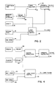
- FIG. 2 is a schematic diagram of a control circuit 30 of the measuring system.
- the control circuit 30 includes a laser pulser control 32 which regulates the operation of the first laser source 10.
- a first timing pulse is transmitted by the laser pulser control 32 to a timing analyser 34.
- the light sensor 16 intercepts the light emanating from the second laser source 14 and reflected by the material, and transmits a pulse to a preamplifier (preamp) level detector 36 which, in turn, transmits a second timing pulse to the timing analyser 34.
- preamp preamplifier
- An output of the preamp level detector 36 is connected to an input to the laser pulser control 32 and causes the pulser control 32 to increase or decrease the magnitude of the pulses produced by first laser source 10 so that the ultrasonic pulses detected by the light sensor 16 will be of sufficient magnitude for detection purposes.
- the timing analyser 34 determines the elapsed time ⁇ t between the transmission of the first timing pulse by the laser pulser control 32 and the receipt of the second timing pulse from the preamp level detector 36.
- the elapsed time ⁇ t and the known distance d between the points of impingement on the web 12 of the beams emanating from the laser sources 10 and 14 are then combined in a strength calculation device 40 with a measurement of material density provided by a density measuring device 38 to determine the velocity v of the ultrasonic wave within the material whose strength is being measured.
- An appropriate density measuring device 38 is disclosed in US Patent No. US-A-3 586 601 entitled “Basis Weight Control System for a Paper Making Machine. "The strength calculating device 40, which can be a microprocessor, determines the strength of the material since material strength is proportional to k1v2, where v is the speed of sound in the material.
- a maximum laser level control 42 and a web speed control 44 are provided as inputs to the laser pulser control 32.
- the maximum laser level control 42 ensures that the first laser source 10 causes no damage to the material whose strength is being measured and a web speed signal from the web speed control 44 allows the laser level to increase as the web speed increases.
- FIG 3 An alternative embodiment of the invention is shown in Figure 3.
- two sensing arrangements are employed.
- some of the elements of Figure 3 are the same as those shown in Figure 1 and are designated by the same reference numerals, further discussion of same will not be undertaken.
- the main advantage of this embodiment is that the use of two sensing arrangements permits correlation of the received wave shapes using digital correlation or digital signal processing techniques so as to improve the accuracy of the resulting strength measurement and to allow for less precision and repeatability in the shape of the generated ultrasonic wave.
- Figure 4 illustrates a control circuit utilised by the embodiment illustrated in Figure 3.
- a digital correlator 46 which, as previously indicated, correlates the wave shapes received by the light sensors 16 and utilises digital correlation or digital signal processing techniques to determine the time required for the ultrasonic wave shape to traverse the web of material. Since two light sensors are utilised in the embodiment shown in Figures 3 and 4, it is possible to use less precise and less expensive pulse sources to induce the waves in the moving web 12 of material.
Abstract
Description
- This invention relates to measuring the strength of material within a web.
- A major quality consideration for the production of sheet materials, such as paper, is strength. Until recently, all strength measurements with respect to such sheet materials were made by off-line laboratory measurements. Recently, on-line measurements have been introduced using contacting gauging techniques that rely on the relationship between Young's Modulus and the speed of sound according to the equation:
Y = k₁.s²
where k₁ is a function of the density of the material and s is the speed of sound within the material. - Methods proposed by Baum and Habeger, as set forth in US Patent No. US-A-4 291 577, and others, rely on rotating wheels which contact a moving web of paper or other material whose strength is being measured. The wheels contain piezoelectric or magnetostrictive transducers in their outer peripheries to create a localised contraction and expansion in the moving web of material. This contraction and expansion creates a sonic wave that travels radially from the spot of creation. Measuring the speed of sound within the material, which is the reciprocal of the transit time between two points of known separation, is used in conjunction with the density of the material to provide a measurement of the strength of the material. This approach has some inherent disadvantages, among which are that the required commutation and mechanical contact produce a signal that contains a significant amount of noise, the rotating wheels are prone to fail, mechanical structures are inevitably more costly and have more parts than electronic devices, the direct contact of the wheels with the material limits the measurement of strength to a single direction (either across the web or along the web), and mechanical methods with slippage and commutation are inherently less accurate than non-mechanical methods.
- Photoacoustic interaction has been used to induce ultrasonic waves into a continuous, fast moving web of paper. US Patent No. US-A-674 332 (Pace et al) discloses the use of a nitrogen laser to illuminate paper with high power ultraviolet pulses. A portion of this optical energy is converted into heat, creating an acoustic wave from the resulting thermal expansion. A contacting, ultrasonic sensor or a microphone positioned on the opposite side of the paper receives the acoustic wave and provides an indication of the speed of sound through the paper, which can be utilised to determine the strength of the paper in its direction of movement.
- Another application of a laser to generate acoustic waves in paper is disclosed in US Patent No. US-A-4 622 853 (Leugers). The apparatus disclosed in this document utilises a Neodymium/Yttrium-Aluminium-Garnet (Nd/YAG) laser with a frequency doubler to illuminate a spot on a moving web of paper. An ultrasonic wave in the paper is detected by an ultrasonic transducer in contact with the paper.
- Because of the disadvantages that are inherent in a measuring system that requires contact with the material whose strength is being measured, it has become desirable to develop an on-line measuring system that does not require such contact.
- According to one aspect of the invention there is provided a system for a system for measuring the strength of material within a web without contacting the web, the system comprising a first light beam source arranged such that a light beam therefrom contacts the material and induces an ultrasonic wave therein, detecting means for detecting said ultrasonic wave at a predetermined distance from a point of inducement of said ultrasonic wave within the material, means for determining the velocity of said ultrasonic wave within the material, means for determining the density of the material, and means for determining the strength of the material based on the velocity of said ultrasonic wave within the material and the density of the material.
- According to another aspect of the invention there is provided a method of measuring the strength of material within a web, the method comprising the steps of:
directing a light beam towards the material to cause an ultrasonic wave to be induced therein;
determining the presence of said ultrasonic wave within the material at a location a predetermined distance away from a point where said ultrasonic wave was induced;
determining the velocity of said ultrasonic wave within the material; and
combining the velocity of said ultrasonic wave with the density of the material to determine the strength of the material. - Preferred embodiments of the invention described hereinbelow solve or at least alleviate the above-mentioned problems associated with the prior art by providing an on-line system that measures the strength of material within a web without contacting same. The foregoing is accomplished by utilising two spaced-apart laser sources having beams which intercept the web of material whose strength is being measured. The distance between the points of impingement on the web of the beams from the laser sources is known. The first laser source generates localised spot heating which creates thermal expansion in the web of material. This thermal expansion creates an ultrasonic wave which propagates through the web in a radial direction. The wave causes the beam from the second laser source to be reflected by the material and the reflected beam is intercepted by a light sensor. By calculating the elapsed time between the transmission of the first beam into the material and the receipt of the second beam by the light sensor, the velocity of the ultrasonic wave within the material can be determined. The velocity of the ultrasonic wave is then combined with a measurement of the density of the material to determine the strength of the material.
- The invention will now be further described, by way of illustrative and non-limiting example, with reference to the accompanying drawings, in which similar references designate similar items throughout, and in which:
- Figure 1 is a schematic diagram of a strength measuring system embodying the invention;
- Figure 2 is a schematic diagram of a control circuit utilised by the measuring system shown in Figure 1;
- Figure 3 is a schematic diagram of an alternative strength measuring system embodying the invention which utilises two light sensors; and
- Figure 4 is a schematic diagram of a control circuit utilised by the measuring system shown in Figure 3.
- Figure 1 is a schematic diagram of a strength measuring system embodying the invention that includes a
first laser source 10 directed towards aweb 12 of material whose strength is to be measured, asecond laser source 14 similarly directed towards theweb 12, and alight sensor 16 located adjacent thesecond laser source 14 and positioned so that its focal point is coincident with the point of impingement of the beam from thesecond laser source 14 on theweb 12. The distance "d" between the points of impingement of the beams from thelaser sources web 12 is known. - The present system utilises an ultrasonic wave pattern induced into the moving
web 12 of material by pulses produced by thefirst laser source 10, which generates localised spot heating. Such localised spot heating creates thermal expansion in the material whose strength is being measured. This expansion perturbation creates a wave which propagates through theweb 12 of material in a radial direction, giving anelliptical wavefront 18, due to anisotropy of the wave velocity with the direction of web movement. Measurement of wave velocity in a particular direction can be utilised to determine the strength of the material in that direction. - The
light sensor 16 measures thewavefront 18 by viewing the crests and valleys of the ultrasonic wave as it passes thereunder. Separate viewing laser and light detection systems may be used for the cross-travel direction and the width-travel direction, or a single system may be scanned to read both directions. The time of arrival of the sensed pulse is compared with the time of impingement of the beam from thefirst laser source 10 into theweb 12 of material, and the difference in time is utilised to calculate the speed of sound within the material. The foregoing speed of sound is then used in conjunction with the density of the material to determine the strength of the material being tested. The foregoing system operates at the speed of light and, as such, any time delays are inconsequential. - The
first laser source 10 is a CO₂ laser having an output power of approximately 5.5 watts and is typically pulsed at a rate of 10 pulses per second, producing a pulse having a width of approximately 100 microseconds or less. Thesecond laser source 14 is a HeNe laser which has an output power of approximately 2 milliwatts and which is operated continuously. Thelight sensor 16 can be a silicon photodetector producing an output in the millivolt range. - Figure 2 is a schematic diagram of a
control circuit 30 of the measuring system. Thecontrol circuit 30 includes alaser pulser control 32 which regulates the operation of thefirst laser source 10. Each time thefirst laser source 10 is pulsed, a first timing pulse is transmitted by thelaser pulser control 32 to atiming analyser 34. After the resulting ultrasonic wave caused by the pulse produced by thefirst laser source 10 has propagated through the material whose strength is being measured, thelight sensor 16 intercepts the light emanating from thesecond laser source 14 and reflected by the material, and transmits a pulse to a preamplifier (preamp)level detector 36 which, in turn, transmits a second timing pulse to thetiming analyser 34. An output of thepreamp level detector 36 is connected to an input to thelaser pulser control 32 and causes thepulser control 32 to increase or decrease the magnitude of the pulses produced byfirst laser source 10 so that the ultrasonic pulses detected by thelight sensor 16 will be of sufficient magnitude for detection purposes. Thetiming analyser 34 determines the elapsed time Δt between the transmission of the first timing pulse by thelaser pulser control 32 and the receipt of the second timing pulse from thepreamp level detector 36. The elapsed time Δt and the known distance d between the points of impingement on theweb 12 of the beams emanating from thelaser sources strength calculation device 40 with a measurement of material density provided by adensity measuring device 38 to determine the velocity v of the ultrasonic wave within the material whose strength is being measured. An appropriatedensity measuring device 38 is disclosed in US Patent No. US-A-3 586 601 entitled "Basis Weight Control System for a Paper Making Machine. "Thestrength calculating device 40, which can be a microprocessor, determines the strength of the material since material strength is proportional to k₁v², where v is the speed of sound in the material. - A maximum
laser level control 42 and aweb speed control 44 are provided as inputs to thelaser pulser control 32. The maximumlaser level control 42 ensures that thefirst laser source 10 causes no damage to the material whose strength is being measured and a web speed signal from theweb speed control 44 allows the laser level to increase as the web speed increases. - An alternative embodiment of the invention is shown in Figure 3. In Figure 3, two sensing arrangements are employed. Inasmuch as some of the elements of Figure 3 are the same as those shown in Figure 1 and are designated by the same reference numerals, further discussion of same will not be undertaken. The main advantage of this embodiment is that the use of two sensing arrangements permits correlation of the received wave shapes using digital correlation or digital signal processing techniques so as to improve the accuracy of the resulting strength measurement and to allow for less precision and repeatability in the shape of the generated ultrasonic wave.
- Figure 4 illustrates a control circuit utilised by the embodiment illustrated in Figure 3. Here again, those elements which are similar to elements shown in Figure 2 are designated by the same reference numerals and will not be discussed. The primary difference between the schematic diagram shown in Figure 4 and that shown in Figure 2 is the use of a
digital correlator 46 which, as previously indicated, correlates the wave shapes received by thelight sensors 16 and utilises digital correlation or digital signal processing techniques to determine the time required for the ultrasonic wave shape to traverse the web of material. Since two light sensors are utilised in the embodiment shown in Figures 3 and 4, it is possible to use less precise and less expensive pulse sources to induce the waves in the movingweb 12 of material. - Each of the above-described embodiments of the invention provides the following advantages:
- 1) the measuring system is on-line and does not contact the web of material;
- 2) the system has omnidirectional measurement capability;
- 3) material strength can be determined across the entire web of material;
- 4) the system is adaptable to rough or hot material surfaces;
- 5) the system can utilise digital signal processing techniques; and
- 6) power levels are variable in order to optimise operation of the system without causing damage to the web of material.
Claims (7)
directing (10) a light beam towards the material to cause an ultrasonic wave to be induced therein;
determining the presence of said ultrasonic wave within the material at a location a predetermined distance (d) away from a point where said ultrasonic wave was induced;
determining (34) the velocity of said ultrasonic wave within the material; and
combining (40) the velocity of said ultrasonic wave with the density of the material to determine the strength of the material.
Applications Claiming Priority (2)
| Application Number | Priority Date | Filing Date | Title |
|---|---|---|---|
| US07/359,536 US5025665A (en) | 1989-06-01 | 1989-06-01 | Non-contacting on-line paper strength measuring system |
| US359536 | 1989-06-01 |
Publications (3)
| Publication Number | Publication Date |
|---|---|
| EP0400770A2 true EP0400770A2 (en) | 1990-12-05 |
| EP0400770A3 EP0400770A3 (en) | 1991-04-17 |
| EP0400770B1 EP0400770B1 (en) | 1994-11-02 |
Family
ID=23414251
Family Applications (1)
| Application Number | Title | Priority Date | Filing Date |
|---|---|---|---|
| EP90300436A Expired - Lifetime EP0400770B1 (en) | 1989-06-01 | 1990-01-16 | Measuring the strength of a material within a moving web |
Country Status (8)
| Country | Link |
|---|---|
| US (1) | US5025665A (en) |
| EP (1) | EP0400770B1 (en) |
| JP (1) | JPH0643945B2 (en) |
| AU (1) | AU628574B2 (en) |
| CA (1) | CA2011912A1 (en) |
| DE (1) | DE69013757T2 (en) |
| DK (1) | DK134690A (en) |
| NO (1) | NO900047L (en) |
Cited By (3)
| Publication number | Priority date | Publication date | Assignee | Title |
|---|---|---|---|---|
| FR2746932A1 (en) * | 1996-04-01 | 1997-10-03 | Gen Electric | METHOD AND SYSTEM FOR FORMING IMAGES OF AN OBJECT USING ULTRASOUND AND LASER |
| WO1999049309A2 (en) * | 1998-03-26 | 1999-09-30 | British Nuclear Fuels Plc | Improvements in and relating to inspection |
| US6668654B2 (en) | 2001-08-15 | 2003-12-30 | Lockheed Martin Corporation | Method and apparatus for generating specific frequency response for ultrasound testing |
Families Citing this family (22)
| Publication number | Priority date | Publication date | Assignee | Title |
|---|---|---|---|---|
| US5361638A (en) * | 1990-03-30 | 1994-11-08 | Stfi | Arrangement for measuring mechanical properties of a foil material through use of an excitation unit that includes a laser |
| SE504576C2 (en) * | 1994-10-06 | 1997-03-10 | Lorentzen & Wettre Ab | Device for measuring ultrasound the elastic properties of a moving web of paper |
| SE504575C2 (en) * | 1994-10-06 | 1997-03-10 | Lorentzen & Wettre Ab | Device for ultrasonic measurement of elastic properties of a moving web of paper |
| US5804727A (en) * | 1995-09-01 | 1998-09-08 | Sandia Corporation | Measurement of physical characteristics of materials by ultrasonic methods |
| US5778724A (en) * | 1995-09-07 | 1998-07-14 | Minnesota Mining & Mfg | Method and device for monitoring web bagginess |
| US5640244A (en) * | 1995-11-02 | 1997-06-17 | Abb Industrial Systems, Inc. | Method and apparatus for on-line determination of fiber orientation and anisotropy in a non-woven web |
| US5678447A (en) * | 1996-04-17 | 1997-10-21 | Eastman Kodak Company | On-line web planarity measurement apparatus and method |
| US5814730A (en) * | 1996-06-10 | 1998-09-29 | Institute Of Paper Science And Technology And Georgia Institute Of Technology | Material characteristic testing method and apparatus using interferometry to detect ultrasonic signals in a web |
| US6356846B1 (en) * | 1998-10-13 | 2002-03-12 | Institute Of Paper Science And Technology, Inc. | System and method of reducing motion-induced noise in the optical detection of an ultrasound signal in a moving body of material |
| WO2000026628A1 (en) * | 1998-11-04 | 2000-05-11 | National Research Council Of Canada | Laser-ultrasonic measurement of elastic properties of a thin sheet and of tension applied thereon |
| US6628408B1 (en) * | 1999-04-15 | 2003-09-30 | Kimberly-Clark Worldwide, Inc. | Amplitude measurement for an ultrasonic horn |
| JP2003057027A (en) * | 2001-08-10 | 2003-02-26 | Ebara Corp | Measuring instrument |
| US6813941B2 (en) | 2001-12-20 | 2004-11-09 | Kimberly-Clark Worldwide, Inc. | Method to measure tension in a moving web and to control properties of the web |
| US6795191B2 (en) * | 2002-01-04 | 2004-09-21 | Freescale Semiconductor, Inc. | Ultrasonically assisted optical media sensor system |
| DE102007015365A1 (en) * | 2007-03-28 | 2008-10-02 | Man Roland Druckmaschinen Ag | Method for determining the degree of cure or degree of dryness of printing ink and varnish layers in printing presses |
| DE102007030566A1 (en) * | 2007-03-28 | 2008-10-02 | Man Roland Druckmaschinen Ag | Non-destructive testing of curing or drying of paints and varnishes |
| JP5358335B2 (en) | 2009-07-28 | 2013-12-04 | トヨタ自動車株式会社 | Inspection device |
| US8728276B2 (en) * | 2010-05-20 | 2014-05-20 | Honeywell International Inc. | Apparatus and method for controlling curling potential of paper, paperboard, or other product during manufacture |
| DE102011006391A1 (en) * | 2011-03-30 | 2012-10-04 | Siemens Aktiengesellschaft | Method and device for detecting parameters of a continuous or circulating material web in a material processing machine |
| CN102564895B (en) * | 2012-01-04 | 2013-07-03 | 燕山大学 | Liquid density on-line monitoring system based on ultrasonic diffraction grating |
| EP3491333B1 (en) | 2016-07-28 | 2022-03-30 | Renishaw PLC | Non-contact probe and method of operation |
| US10365252B2 (en) * | 2017-02-13 | 2019-07-30 | Eric M. STROHM | Method and apparatus for sensing a sample |
Citations (2)
| Publication number | Priority date | Publication date | Assignee | Title |
|---|---|---|---|---|
| US4622853A (en) * | 1985-08-23 | 1986-11-18 | Union Camp Corporation | Laser induced acoustic generation for sonic modulus |
| US4674332A (en) * | 1986-02-20 | 1987-06-23 | Union Camp Corporation | Laser induced acoustic generation for sonic modulus |
Family Cites Families (3)
| Publication number | Priority date | Publication date | Assignee | Title |
|---|---|---|---|---|
| US3952583A (en) * | 1975-01-02 | 1976-04-27 | The United States Of America As Represented By The Secretary Of The Army | Apparatus and method for the remote detection of vibrations of diffuse surfaces |
| US4291577A (en) * | 1979-12-03 | 1981-09-29 | The Institute Of Paper Chemistry | On line ultrasonic velocity gauge |
| FI79410C (en) * | 1986-06-09 | 1989-12-11 | Stroemberg Oy Ab | FOERFARANDE OCH ANORDNING FOER KONTAKTLOES MAETNING AV SPAENNINGEN HOS EN PLAN FOLIE OCH ISYNNERHET EN PAPPERSBANA. |
-
1989
- 1989-06-01 US US07/359,536 patent/US5025665A/en not_active Expired - Fee Related
-
1990
- 1990-01-05 NO NO90900047A patent/NO900047L/en unknown
- 1990-01-16 EP EP90300436A patent/EP0400770B1/en not_active Expired - Lifetime
- 1990-01-16 DE DE69013757T patent/DE69013757T2/en not_active Expired - Fee Related
- 1990-03-09 CA CA002011912A patent/CA2011912A1/en not_active Abandoned
- 1990-05-29 AU AU56062/90A patent/AU628574B2/en not_active Ceased
- 1990-05-31 JP JP2140141A patent/JPH0643945B2/en not_active Expired - Lifetime
- 1990-05-31 DK DK134690A patent/DK134690A/en not_active Application Discontinuation
Patent Citations (2)
| Publication number | Priority date | Publication date | Assignee | Title |
|---|---|---|---|---|
| US4622853A (en) * | 1985-08-23 | 1986-11-18 | Union Camp Corporation | Laser induced acoustic generation for sonic modulus |
| US4674332A (en) * | 1986-02-20 | 1987-06-23 | Union Camp Corporation | Laser induced acoustic generation for sonic modulus |
Non-Patent Citations (2)
| Title |
|---|
| IEEE, ULTRASONICS SYMPOSIUM vol. 1, 1986, pages 515-526; P. CIELO et al.: "Laser generation of convergent acoustic waves and applications to materials evaluation" * |
| MESURES. REGULATION AUTOMATISME vol. 49, no. 8, May 1984, pages 73-77, Paris, F; "CND: des ultrasons sans contact" * |
Cited By (4)
| Publication number | Priority date | Publication date | Assignee | Title |
|---|---|---|---|---|
| FR2746932A1 (en) * | 1996-04-01 | 1997-10-03 | Gen Electric | METHOD AND SYSTEM FOR FORMING IMAGES OF AN OBJECT USING ULTRASOUND AND LASER |
| WO1999049309A2 (en) * | 1998-03-26 | 1999-09-30 | British Nuclear Fuels Plc | Improvements in and relating to inspection |
| WO1999049309A3 (en) * | 1998-03-26 | 1999-11-11 | British Nuclear Fuels Plc | Improvements in and relating to inspection |
| US6668654B2 (en) | 2001-08-15 | 2003-12-30 | Lockheed Martin Corporation | Method and apparatus for generating specific frequency response for ultrasound testing |
Also Published As
| Publication number | Publication date |
|---|---|
| NO900047L (en) | 1990-12-03 |
| US5025665A (en) | 1991-06-25 |
| EP0400770B1 (en) | 1994-11-02 |
| DE69013757D1 (en) | 1994-12-08 |
| DK134690A (en) | 1990-12-02 |
| JPH03162645A (en) | 1991-07-12 |
| DK134690D0 (en) | 1990-05-31 |
| EP0400770A3 (en) | 1991-04-17 |
| AU5606290A (en) | 1990-12-06 |
| DE69013757T2 (en) | 1995-03-09 |
| NO900047D0 (en) | 1990-01-05 |
| JPH0643945B2 (en) | 1994-06-08 |
| AU628574B2 (en) | 1992-09-17 |
| CA2011912A1 (en) | 1990-12-01 |
Similar Documents
| Publication | Publication Date | Title |
|---|---|---|
| EP0400770A2 (en) | Measuring the strength of a material within a moving web | |
| EP0083979B1 (en) | Interferometric contact-free method for testing workpieces using ultrasonic wave vibrations | |
| US6837109B2 (en) | Material thickness measurement method and apparatus | |
| US6543288B1 (en) | Laser-ultrasonic measurement of elastic properties of a thin sheet and of tension applied thereon | |
| Osumi et al. | Imaging slit in metal plate using aerial ultrasound source scanning and nonlinear harmonic method | |
| US5361638A (en) | Arrangement for measuring mechanical properties of a foil material through use of an excitation unit that includes a laser | |
| JP2001194137A (en) | Non-contact measuring method and apparatus for material thickness | |
| JP2002213936A (en) | Method and device for non-contact measurement of thickness of material | |
| KR100496826B1 (en) | Apparatus and method of noncontact measurement of crystal grain size | |
| JPS6247549A (en) | Non-destructive testing method and device of physical property of workpiece absorbing beam without physical contact | |
| US6445457B1 (en) | Laser detection of material thickness | |
| US6496268B1 (en) | Laser-based glass thickness measurement system and method | |
| JPS5831872B2 (en) | Non-contact ultrasonic flaw detection method | |
| EP0028540B1 (en) | Method and apparatus for non-contact acoustic measurement of physical properties of continuously moving metal strip | |
| EP0479979B1 (en) | Arrangement for measuring mechanical properties of a foil material | |
| JPH07253414A (en) | Method and apparatus for ultrasonic flaw detection | |
| JPS5658658A (en) | Measuring method of grain size of steel material using pulse laser light | |
| KR20020011662A (en) | Method of Detecting Internal Cracks of Steel Products using Laser-Ultrasonic | |
| WO2002103347A2 (en) | Grain-size measurement | |
| SU859812A2 (en) | Ultrasonic method of measuring thickness | |
| Dewhurst et al. | A study of Lamb wave interaction with defects in sheet materials using a differential fibre-optic beam deflection technique | |
| JPH0658348B2 (en) | Ultrasonic vibration mode determination device | |
| RU2006855C1 (en) | Method of testing articles using acoustic emission | |
| HUANG | Laser-based ultrasonics by dual-probe interferometer detection and narrow-band ultrasound generation(Ph. D. Thesis) | |
| KR100322031B1 (en) | Method and device for detecting flaw by using acoustic wave |
Legal Events
| Date | Code | Title | Description |
|---|---|---|---|
| PUAI | Public reference made under article 153(3) epc to a published international application that has entered the european phase |
Free format text: ORIGINAL CODE: 0009012 |
|
| AK | Designated contracting states |
Kind code of ref document: A2 Designated state(s): BE DE FR GB IT SE |
|
| RAP1 | Party data changed (applicant data changed or rights of an application transferred) |
Owner name: INTERNATIONAL CONTROL AUTOMATION FINANCE S.A. |
|
| PUAL | Search report despatched |
Free format text: ORIGINAL CODE: 0009013 |
|
| AK | Designated contracting states |
Kind code of ref document: A3 Designated state(s): BE DE FR GB IT SE |
|
| 17P | Request for examination filed |
Effective date: 19910809 |
|
| 17Q | First examination report despatched |
Effective date: 19930317 |
|
| GRAA | (expected) grant |
Free format text: ORIGINAL CODE: 0009210 |
|
| AK | Designated contracting states |
Kind code of ref document: B1 Designated state(s): BE DE FR GB IT SE |
|
| REF | Corresponds to: |
Ref document number: 69013757 Country of ref document: DE Date of ref document: 19941208 |
|
| ET | Fr: translation filed | ||
| ITF | It: translation for a ep patent filed |
Owner name: MARIETTI E GISLON S.R.L. |
|
| PG25 | Lapsed in a contracting state [announced via postgrant information from national office to epo] |
Ref country code: SE Effective date: 19950202 |
|
| PLBE | No opposition filed within time limit |
Free format text: ORIGINAL CODE: 0009261 |
|
| STAA | Information on the status of an ep patent application or granted ep patent |
Free format text: STATUS: NO OPPOSITION FILED WITHIN TIME LIMIT |
|
| 26N | No opposition filed | ||
| PGFP | Annual fee paid to national office [announced via postgrant information from national office to epo] |
Ref country code: GB Payment date: 19951228 Year of fee payment: 7 |
|
| PGFP | Annual fee paid to national office [announced via postgrant information from national office to epo] |
Ref country code: BE Payment date: 19951229 Year of fee payment: 7 |
|
| PGFP | Annual fee paid to national office [announced via postgrant information from national office to epo] |
Ref country code: FR Payment date: 19961220 Year of fee payment: 8 |
|
| PGFP | Annual fee paid to national office [announced via postgrant information from national office to epo] |
Ref country code: DE Payment date: 19961223 Year of fee payment: 8 |
|
| PG25 | Lapsed in a contracting state [announced via postgrant information from national office to epo] |
Ref country code: GB Effective date: 19970116 |
|
| PG25 | Lapsed in a contracting state [announced via postgrant information from national office to epo] |
Ref country code: BE Effective date: 19970131 |
|
| BERE | Be: lapsed |
Owner name: S.A. INTERNATIONAL CONTROL AUTOMATION FINANCE Effective date: 19970131 |
|
| GBPC | Gb: european patent ceased through non-payment of renewal fee |
Effective date: 19970116 |
|
| PG25 | Lapsed in a contracting state [announced via postgrant information from national office to epo] |
Ref country code: FR Free format text: THE PATENT HAS BEEN ANNULLED BY A DECISION OF A NATIONAL AUTHORITY Effective date: 19980131 |
|
| PG25 | Lapsed in a contracting state [announced via postgrant information from national office to epo] |
Ref country code: DE Free format text: LAPSE BECAUSE OF NON-PAYMENT OF DUE FEES Effective date: 19981001 |
|
| REG | Reference to a national code |
Ref country code: FR Ref legal event code: ST |
|
| PG25 | Lapsed in a contracting state [announced via postgrant information from national office to epo] |
Ref country code: IT Free format text: LAPSE BECAUSE OF NON-PAYMENT OF DUE FEES;WARNING: LAPSES OF ITALIAN PATENTS WITH EFFECTIVE DATE BEFORE 2007 MAY HAVE OCCURRED AT ANY TIME BEFORE 2007. THE CORRECT EFFECTIVE DATE MAY BE DIFFERENT FROM THE ONE RECORDED. Effective date: 20050116 |