EP0400628A1 - Self-sealing valve for implantable device - Google Patents
Self-sealing valve for implantable device Download PDFInfo
- Publication number
- EP0400628A1 EP0400628A1 EP90110302A EP90110302A EP0400628A1 EP 0400628 A1 EP0400628 A1 EP 0400628A1 EP 90110302 A EP90110302 A EP 90110302A EP 90110302 A EP90110302 A EP 90110302A EP 0400628 A1 EP0400628 A1 EP 0400628A1
- Authority
- EP
- European Patent Office
- Prior art keywords
- fill tube
- valve
- channel
- gel
- main body
- Prior art date
- Legal status (The legal status is an assumption and is not a legal conclusion. Google has not performed a legal analysis and makes no representation as to the accuracy of the status listed.)
- Granted
Links
Images


Classifications
-
- A—HUMAN NECESSITIES
- A61—MEDICAL OR VETERINARY SCIENCE; HYGIENE
- A61F—FILTERS IMPLANTABLE INTO BLOOD VESSELS; PROSTHESES; DEVICES PROVIDING PATENCY TO, OR PREVENTING COLLAPSING OF, TUBULAR STRUCTURES OF THE BODY, e.g. STENTS; ORTHOPAEDIC, NURSING OR CONTRACEPTIVE DEVICES; FOMENTATION; TREATMENT OR PROTECTION OF EYES OR EARS; BANDAGES, DRESSINGS OR ABSORBENT PADS; FIRST-AID KITS
- A61F2/00—Filters implantable into blood vessels; Prostheses, i.e. artificial substitutes or replacements for parts of the body; Appliances for connecting them with the body; Devices providing patency to, or preventing collapsing of, tubular structures of the body, e.g. stents
- A61F2/02—Prostheses implantable into the body
- A61F2/12—Mammary prostheses and implants
-
- A—HUMAN NECESSITIES
- A61—MEDICAL OR VETERINARY SCIENCE; HYGIENE
- A61F—FILTERS IMPLANTABLE INTO BLOOD VESSELS; PROSTHESES; DEVICES PROVIDING PATENCY TO, OR PREVENTING COLLAPSING OF, TUBULAR STRUCTURES OF THE BODY, e.g. STENTS; ORTHOPAEDIC, NURSING OR CONTRACEPTIVE DEVICES; FOMENTATION; TREATMENT OR PROTECTION OF EYES OR EARS; BANDAGES, DRESSINGS OR ABSORBENT PADS; FIRST-AID KITS
- A61F2250/00—Special features of prostheses classified in groups A61F2/00 - A61F2/26 or A61F2/82 or A61F9/00 or A61F11/00 or subgroups thereof
- A61F2250/0003—Special features of prostheses classified in groups A61F2/00 - A61F2/26 or A61F2/82 or A61F9/00 or A61F11/00 or subgroups thereof having an inflatable pocket filled with fluid, e.g. liquid or gas
-
- Y—GENERAL TAGGING OF NEW TECHNOLOGICAL DEVELOPMENTS; GENERAL TAGGING OF CROSS-SECTIONAL TECHNOLOGIES SPANNING OVER SEVERAL SECTIONS OF THE IPC; TECHNICAL SUBJECTS COVERED BY FORMER USPC CROSS-REFERENCE ART COLLECTIONS [XRACs] AND DIGESTS
- Y10—TECHNICAL SUBJECTS COVERED BY FORMER USPC
- Y10T—TECHNICAL SUBJECTS COVERED BY FORMER US CLASSIFICATION
- Y10T137/00—Fluid handling
- Y10T137/3584—Inflatable article [e.g., tire filling chuck and/or stem]
Definitions
- the present invention relates to self-sealing valves, and in particular, it relates to self-sealing valves for use in implantable devices.
- Implantable devices that are used both as a skin expander and a breast prosthesis have become increasingly popular. Initially, this type of expander/prosthesis is implanted in a deflated state in a pocket surgically made in the breast area.
- the device includes an inflatable chamber, and a subcutaneously implanted injection site which is connected to the inflatable chamber through a fill tube.
- the fill tube is connected to the inflatable chamber by a valve which has the ability to seal once the fill tube is pulled.
- the fill tube is pulled out of the valve and is removed from its subcutaneous location along with the injection site. Upon removal the valve must seal and the expander now acts as a prosthesis.
- the key to such a device functioning properly is the ability of the valve to seal once the fill tube is removed, such that there is absolutely no leakage.
- a practical aspect of implantation of such devices is that from the time the device is manufactured to the time that the fill tube is pulled from the valve may be two years or more. It has been found that stresses are placed in the valve material which surrounds the fill tube to an extent that such material does not relax back to its original (closed) position and therefore does not provide an absolute seal once the fill tube is removed.
- valve One type of valve that has been used is made of two sheets of silicone elastomer bonded together along edge portions to form a passage between the bonded edge portions.
- a fill tube is typically inserted within the passage. If the fill tube is in the passage for any length of time, the silicone rubber around the passage area is stressed, resulting in the valve not sealing adequately once the fill tube is removed. The passage becomes somewhat “set” over time and cannot return to its original position once the fill tube has been removed.
- the valve in the Fogerty et al patent has a passage portion which is flanked on opposing sides by first and second portions of elastomeric material.
- the passage portion is in a stretched state relative to the first and second portions so that the passage portion curls along the passage when the fill tube is removed.
- the Boone patent describes an implantable mammary prosthesis including an inflatable shell and a filling stem. At the point of introduction of the stem into the shell, the stem passes through a capsule of sealing gel. After implantation and inflation, the stem is withdrawn either wholly or partially and gel in the capsule seals the stem outlet against leakage of the inflating fluid.
- valves which are constructed of two sheets of silicone elastomer bonded together along two edges to form a passage. None of the valves illustrated in the immediately below-listed patents are constructed to avoid the passage being permanently deformed due to the stress caused by the fill tube being present in the passage over a long period of time: Inventor Patent No. Hyans U.S. 4,459,318 Bejarano U.S. 4,263,682 Cox, Jr. U.S. 4,178,643 Koneke et al U.S. 3,852,833 McGhan et al U.S. 3,852,832 Valliancourt et al U.S. 3,565,078 Krueger U.S. 2,697,229
- the present invention includes a valve having a main body portion with a channel for receiving a fill tube.
- the main body portion includes first and second elastomeric layers which define the channel for receiving the fill tube and wherein one portion of an elastomeric layer is restrained while a portion of a second elastomeric layer is unrestrained such that the main body portion flexes in the area of the unrestrained second elastomeric layer to an extent that the channel is occluded.
- the present invention also includes a valve having a gel chamber in which the main body portion is disposed.
- the main body portion has a free end which is occluded with gel once the fill tube is withdrawn from the fill tube channel.
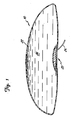
- a skin expander/mammary prosthesis generally indicated at 10 incorporating the valve 20 of the present invention is illustrated in Figure 1.
- the prosthesis 10 includes an outer shell 22 defining an inflation chamber 24.
- a fill tube 26 extends through the valve 20 into the chamber 24 providing access for fluid to flow into or out of the chamber 24. Fluid is provided through a subcutaneous injection site (not shown) connected to the fill tube.
- a single chamber expander/prosthesis is illustrated, it is understood that the valve of the present invention can be used in multiple chambered prostheses. For example, in a double-chambered mammary prosthesis, two valves would be used, a first valve providing access through the inner shell and a second valve providing access through the outer shell.
- a common fill tube can extend through each of the valves, such as is described in the Bell et al U.S. Patent 4,662,883, or a separate fill tube can extend through each of the valves.
- the general construction of the valve 20 is best illustrated by reference to Figures 2 and 3.
- the valve 20 includes a gel filled chamber 28.
- a fill tube channel member 30 is disposed within the chamber 28.
- the channel member 30 includes an unevenly stressed portion 32 and a free end portion 34.
- the gel chamber 28 is preferably constructed of an outer circular sheet 36 of vulcanized silicone elastomer joined to an inner circular sheet 37 of vulcanized silicone elastomer using a ring 40 of unvulcanized silicone elastomer to bond sheets 36 and 37 together for forming the chamber 28.
- the channel member 30, through which the fill tube passes, is constructed by bonding two sheets of silicone elastomer to form the channel member 30. Prior to bonding the sheets of silicone elastomer, a removable teflon ribbon is placed between the two sheets to form a fill tube channel 38 into which the fill tube is positioned. Once the two sheets of silicone elastomer are bonded to form the channel member 30 and the channel 38, the teflon ribbon is removed.
- the valve further includes a fill tube entry member 39 having a fill tube passage opening 41.
- the member 39 attaches channel member 30 to the sheet 36 and provides an access opening into the fill tube passage.
- the channel member 30 is stretched as indicated by arrows 35 in Figure 4.
- an unstretched sheet 42 of silicone elastomer is attached to one side of the channel member 30 over the channel 38 and first and second pieces 44 and 46 of unstretched silicone elastomer are attached on the opposite side of the channel 38 from the sheet 42.
- the unstretched sheet 42 of silicone elastomer is positioned over a selected section of the fill tube channel 38.
- the pieces 44 and 46 are spaced apart and also overlie the channel 38 on an opposite side from the sheet 42.
- the spacing of the pieces 44 and 46 define the boundaries of the unevenly stressed portion 32, that is, the portion of the sheet 42 which is not opposed by either pieces 44 or 46. It will be appreciated that bonding pieces 44 and 46 overlying the fill tube channel 38 in opposing relationship to the piece 42 while the fill tube channel 38 is in a stretched condition will result in an unevenly stressed state in portion 32.
- the layer of elastomer in portion 32 will relax and contract since that portion is not being restrained in a stretched position.
- the piece 42 and the pieces 44 and 46 when bonded to the stretched channel member 30 restrain the channel member surrounding the channel from relaxing.
- the portion 32 between the pieces 44 and 46 which is not so restrained will relax and contract when the channel member 30 is released or when the-fill tube is withdrawn.
- the portion 32 due to the uneven stresses, flexes such that the fill tube channel 38 folds over on itself, as illustrated in Figure 5.
- the folding over of the fill tube channel causes the two layers of silicone in the portion 32 to come in contact with each other along their inner surfaces, that is the surfaces forming the channel wall resulting in a closure of the channel.
- the gel in the chamber 28 provides an additional seal.
- the gel is a partially cross-linked, unfilled, silicone elastomer that is conventionally used in the construction of mammary prostheses.
- the gel provides both a static and a dynamic sealing mechanism.
- the dynamic mechanism includes the inclusion of cohesive gel into the fill tube channel when the fill tube is pulled from channel. As illustrated in Figures 2 and 3, an exposed portion 49 of the fill tube is in direct contact with the gel in the chamber 28. When the fill tube is pulled in the direction indicated by arrow 43, gel will be pulled into the fill tube channel resulting in occlusion of the channel by the gel.
- a further sealing mechanism 45 is provided by the valve of the present invention.
- the sealing mechanism 45 is located along the periphery of the valve and provides the opening through which the fill tube extends into the inflation chamber 24 of the prosthesis.
- the mechanism 45 includes a fill tube channel 47 defined by layers 48 and 50 of silicone elastomer that are bonded together in a conventional fashion. When the fill tube 26 is pulled, the fill tube channel 47 closes due to the elastomeric nature of silicone layers 48 and 50.
- the fill tube channel 47 becomes filled with gel and the gel acts as an additional barrier to keep fluid out from the gel chamber.
Abstract
Description
- The present invention relates to self-sealing valves, and in particular, it relates to self-sealing valves for use in implantable devices.
- In recent developments in inflatable prosthetic devices, it has been found desirable to progressively inflate the prosthetic device over a period of time. This has required the use of subcutaneous injection sites connected to the inflatable prosthetic device by a fill tube.
- Implantable devices that are used both as a skin expander and a breast prosthesis have become increasingly popular. Initially, this type of expander/prosthesis is implanted in a deflated state in a pocket surgically made in the breast area. The device includes an inflatable chamber, and a subcutaneously implanted injection site which is connected to the inflatable chamber through a fill tube. The fill tube is connected to the inflatable chamber by a valve which has the ability to seal once the fill tube is pulled.
- Once the expander/prosthesis is filled to a desired inflation level or the amount of skin expanded reaches a desired level, the fill tube is pulled out of the valve and is removed from its subcutaneous location along with the injection site. Upon removal the valve must seal and the expander now acts as a prosthesis. The key to such a device functioning properly is the ability of the valve to seal once the fill tube is removed, such that there is absolutely no leakage.
- The prior art valves that have been used in such prostheses, although providing a seal, do not provide an absolute seal since some leakage can occur. It will be appreciated that although the leakage rate is slight, and not noticeable over a short period of time, any decrease in fluid volume in the prosthesis over several years is unacceptable.
- A practical aspect of implantation of such devices is that from the time the device is manufactured to the time that the fill tube is pulled from the valve may be two years or more. It has been found that stresses are placed in the valve material which surrounds the fill tube to an extent that such material does not relax back to its original (closed) position and therefore does not provide an absolute seal once the fill tube is removed.
- One type of valve that has been used is made of two sheets of silicone elastomer bonded together along edge portions to form a passage between the bonded edge portions. A fill tube is typically inserted within the passage. If the fill tube is in the passage for any length of time, the silicone rubber around the passage area is stressed, resulting in the valve not sealing adequately once the fill tube is removed. The passage becomes somewhat "set" over time and cannot return to its original position once the fill tube has been removed.
- A curling self-sealing valve is described in Bell et al U.S. Patent 4,662,883 entitled "Self-sealing Valve for Fluid Fillable Device" that provides a seal by curling along the longitudinal axis of the fill tube passage.
- Another self-sealing valve for fluid fillable article is disclosed in the Fogerty et al U.S. Patent 4,775,379. The valve in the Fogerty et al patent has a passage portion which is flanked on opposing sides by first and second portions of elastomeric material. The passage portion is in a stretched state relative to the first and second portions so that the passage portion curls along the passage when the fill tube is removed.
- The Boone patent describes an implantable mammary prosthesis including an inflatable shell and a filling stem. At the point of introduction of the stem into the shell, the stem passes through a capsule of sealing gel. After implantation and inflation, the stem is withdrawn either wholly or partially and gel in the capsule seals the stem outlet against leakage of the inflating fluid.
- A number of other patents directed to prosthetic inflatable devices show valves which are constructed of two sheets of silicone elastomer bonded together along two edges to form a passage. None of the valves illustrated in the immediately below-listed patents are constructed to avoid the passage being permanently deformed due to the stress caused by the fill tube being present in the passage over a long period of time:
Inventor Patent No. Hyans U.S. 4,459,318 Bejarano U.S. 4,263,682 Cox, Jr. U.S. 4,178,643 Koneke et al U.S. 3,852,833 McGhan et al U.S. 3,852,832 Valliancourt et al U.S. 3,565,078 Krueger U.S. 2,697,229 - Other patents describe yet different valve arrangements in breast prosthesis:
Inventor Patent No. Cowen U.S. 4,433,440 Boone U.S. 3,600,718 Leo et al U.S. 2,516,129 - A number of other patents show inflatable devices other than prosthetic devices that include a variety of valving arrangements for the introduction of air. However, these valves in the immediately below-listed patents are also not designed for the retention of a fill tube for a long period of time.
Inventor Patent No. Kampa U.S. 3,584,671 Mirando U.S. 3,523,563 Mondano U.S. 3,410,300 Nicholls U.S. 3,204,959 Siedow U.S. 2,933,120 Blaszkowski et al U.S. 2,826,523 Orms U.S. 2,795,425 Andrews U.S. 2,700,980 Andrews U.S. 2,568,976 Riddell U.S. 2,142,414 Goldsmith et al U.S. 1,551,099 Gregory U.S. 1,008,641 Brookes U.S. 564,502 Ingram U.K. 9,698 Tomkins French 719,244 - The present invention includes a valve having a main body portion with a channel for receiving a fill tube. The main body portion includes first and second elastomeric layers which define the channel for receiving the fill tube and wherein one portion of an elastomeric layer is restrained while a portion of a second elastomeric layer is unrestrained such that the main body portion flexes in the area of the unrestrained second elastomeric layer to an extent that the channel is occluded.
- The present invention also includes a valve having a gel chamber in which the main body portion is disposed. The main body portion has a free end which is occluded with gel once the fill tube is withdrawn from the fill tube channel.
-
- Figure 1 is a cross sectional view of the valve of the present invention in an expander/prosthesis.
- Figure 2 is an exploded perspective view of the valve of the present invention.
- Figure 3 is a sectional view of the valve of the present invention with a fill tube disposed therein.
- Figure 4 is a perspective view of a portion of the valve of the present invention.
- Figure 5 is a sectional view of the valve of the present invention with the fill tube removed.
- A skin expander/mammary prosthesis generally indicated at 10 incorporating the
valve 20 of the present invention is illustrated in Figure 1. The prosthesis 10 includes anouter shell 22 defining aninflation chamber 24. Afill tube 26 extends through thevalve 20 into thechamber 24 providing access for fluid to flow into or out of thechamber 24. Fluid is provided through a subcutaneous injection site (not shown) connected to the fill tube. Although a single chamber expander/prosthesis is illustrated, it is understood that the valve of the present invention can be used in multiple chambered prostheses. For example, in a double-chambered mammary prosthesis, two valves would be used, a first valve providing access through the inner shell and a second valve providing access through the outer shell. A common fill tube can extend through each of the valves, such as is described in the Bell et al U.S. Patent 4,662,883, or a separate fill tube can extend through each of the valves. - The general construction of the
valve 20 is best illustrated by reference to Figures 2 and 3. Thevalve 20 includes a gel filledchamber 28. A filltube channel member 30 is disposed within thechamber 28. Thechannel member 30 includes an unevenly stressedportion 32 and afree end portion 34. - The
gel chamber 28 is preferably constructed of an outercircular sheet 36 of vulcanized silicone elastomer joined to an innercircular sheet 37 of vulcanized silicone elastomer using aring 40 of unvulcanized silicone elastomer tobond sheets chamber 28. - The
channel member 30, through which the fill tube passes, is constructed by bonding two sheets of silicone elastomer to form thechannel member 30. Prior to bonding the sheets of silicone elastomer, a removable teflon ribbon is placed between the two sheets to form afill tube channel 38 into which the fill tube is positioned. Once the two sheets of silicone elastomer are bonded to form thechannel member 30 and thechannel 38, the teflon ribbon is removed. - The valve further includes a fill
tube entry member 39 having a fill tube passage opening 41. Themember 39 attacheschannel member 30 to thesheet 36 and provides an access opening into the fill tube passage. - To form the unevenly stressed
portion 32, thechannel member 30 is stretched as indicated byarrows 35 in Figure 4. After thechannel member 30 is stretched, anunstretched sheet 42 of silicone elastomer is attached to one side of thechannel member 30 over thechannel 38 and first andsecond pieces 44 and 46 of unstretched silicone elastomer are attached on the opposite side of thechannel 38 from thesheet 42. - The
unstretched sheet 42 of silicone elastomer is positioned over a selected section of thefill tube channel 38. Thepieces 44 and 46 are spaced apart and also overlie thechannel 38 on an opposite side from thesheet 42. The spacing of thepieces 44 and 46 define the boundaries of the unevenly stressedportion 32, that is, the portion of thesheet 42 which is not opposed by eitherpieces 44 or 46. It will be appreciated thatbonding pieces 44 and 46 overlying thefill tube channel 38 in opposing relationship to thepiece 42 while thefill tube channel 38 is in a stretched condition will result in an unevenly stressed state inportion 32. The layer of elastomer inportion 32 will relax and contract since that portion is not being restrained in a stretched position. - The
piece 42 and thepieces 44 and 46 when bonded to the stretchedchannel member 30 restrain the channel member surrounding the channel from relaxing. Theportion 32 between thepieces 44 and 46 which is not so restrained will relax and contract when thechannel member 30 is released or when the-fill tube is withdrawn. Theportion 32, due to the uneven stresses, flexes such that thefill tube channel 38 folds over on itself, as illustrated in Figure 5. The folding over of the fill tube channel causes the two layers of silicone in theportion 32 to come in contact with each other along their inner surfaces, that is the surfaces forming the channel wall resulting in a closure of the channel. - Even when the fill tube has been disposed in the
fill tube channel 38 over a lengthy period of time, the folding action caused by the unevenly stressedportion 32 will flatten the fill tube channel. The gel in thechamber 28 provides an additional seal. The gel is a partially cross-linked, unfilled, silicone elastomer that is conventionally used in the construction of mammary prostheses. The gel provides both a static and a dynamic sealing mechanism. - In the static sealing mechanism, once the fill tube is removed from the fill tube channel, the opening of the
end portion 34 of the fill tube channel comes into direct contact with the gel. The presence of the gel acts as a further barrier to leakage. - The dynamic mechanism includes the inclusion of cohesive gel into the fill tube channel when the fill tube is pulled from channel. As illustrated in Figures 2 and 3, an exposed portion 49 of the fill tube is in direct contact with the gel in the
chamber 28. When the fill tube is pulled in the direction indicated byarrow 43, gel will be pulled into the fill tube channel resulting in occlusion of the channel by the gel. - A
further sealing mechanism 45 is provided by the valve of the present invention. Thesealing mechanism 45 is located along the periphery of the valve and provides the opening through which the fill tube extends into theinflation chamber 24 of the prosthesis. Themechanism 45 includes afill tube channel 47 defined bylayers fill tube 26 is pulled, thefill tube channel 47 closes due to the elastomeric nature of silicone layers 48 and 50. - In addition, the
fill tube channel 47 becomes filled with gel and the gel acts as an additional barrier to keep fluid out from the gel chamber. - Although the present invention has been described with reference to preferred embodiments, workers skilled in the art will recognize that changes may be made in form and detail without departing from the spirit and scope of the invention.
Claims (7)
a main body portion having a fill tube channel for receiving the fill tube, and the main body portion being constructed of at least first and second elastomeric layers and wherein the main body portion has an unevenly stressed section that includes a selected section of the channel and wherein the unevenly stressed section is stressed so that the selected section of the channel folds back occluding the channel, when the fill tube is removed from the channel.
a gel-filled chamber; and
wherein the main body portion is disposed in the gel-filled chamber.
a valve chamber having a gel therein; and
a valve member having a fill tube channel for receiving the fill tube and having a free end disposed within the gel such that when the fill tube is removed from the fill tube passage, the valve member flexes to flatten the fill tube passage and the gel occludes the fill tube passage providing a fluid seal.
Applications Claiming Priority (2)
| Application Number | Priority Date | Filing Date | Title |
|---|---|---|---|
| US359481 | 1989-05-31 | ||
| US07/359,481 US5019101A (en) | 1989-05-31 | 1989-05-31 | Self-sealing valve for implantable device |
Publications (2)
| Publication Number | Publication Date |
|---|---|
| EP0400628A1 true EP0400628A1 (en) | 1990-12-05 |
| EP0400628B1 EP0400628B1 (en) | 1994-07-06 |
Family
ID=23413981
Family Applications (1)
| Application Number | Title | Priority Date | Filing Date |
|---|---|---|---|
| EP90110302A Expired - Lifetime EP0400628B1 (en) | 1989-05-31 | 1990-05-30 | Self-sealing valve for implantable device |
Country Status (3)
| Country | Link |
|---|---|
| US (1) | US5019101A (en) |
| EP (1) | EP0400628B1 (en) |
| DE (1) | DE69010401T2 (en) |
Cited By (2)
| Publication number | Priority date | Publication date | Assignee | Title |
|---|---|---|---|---|
| WO2014089192A1 (en) * | 2012-12-05 | 2014-06-12 | Ethicon, Inc. | Valve assemblies for expandable implants and tissue expanders |
| WO2014089178A1 (en) * | 2012-12-06 | 2014-06-12 | Ethicon, Inc. | Valve assemblies for implantable prostheses and tissue expanders |
Families Citing this family (69)
| Publication number | Priority date | Publication date | Assignee | Title |
|---|---|---|---|---|
| GB9107864D0 (en) * | 1991-04-12 | 1991-05-29 | Raychem Sa Nv | Environmental sealing |
| US5964803A (en) * | 1993-07-27 | 1999-10-12 | Pmt Corporation | Enhanced surface implant and method of manufacture |
| US5456716A (en) * | 1993-08-25 | 1995-10-10 | Pmt Corporation | Elastomeric valve assembly |
| US5855606A (en) * | 1996-07-18 | 1999-01-05 | Board Of Trustees Of The University Of Arkansas | Breast prosthesis |
| US5700288A (en) * | 1996-07-18 | 1997-12-23 | The Board Of Trustees Of The University Of Arkansas | Breast prosthesis |
| US5935164A (en) * | 1997-02-25 | 1999-08-10 | Pmt Corporaton | Laminated prosthesis and method of manufacture |
| BR9915854A (en) * | 1998-12-01 | 2001-08-21 | Atropos Ltd | Sealed laparoscopic access device |
| ATE308277T1 (en) | 1998-12-01 | 2005-11-15 | Atropos Ltd | SURGICAL DEVICE FOR RETRACTION AND/OR CLOSING A PITCH |
| US7537564B2 (en) | 1998-12-01 | 2009-05-26 | Atropos Limited | Wound retractor device |
| US7559893B2 (en) | 1998-12-01 | 2009-07-14 | Atropos Limited | Wound retractor device |
| US6283998B1 (en) | 1999-05-13 | 2001-09-04 | Board Of Trustees Of The University Of Arkansas | Alloplastic vertebral disk replacement |
| US6315796B1 (en) | 1999-05-13 | 2001-11-13 | Board Of Trustees Of The University Of Arkansas | Flexible seamless memory tissue expanding implant |
| US7540839B2 (en) * | 1999-10-14 | 2009-06-02 | Atropos Limited | Wound retractor |
| CN1169493C (en) | 1999-10-14 | 2004-10-06 | 阿特波斯有限公司 | A wound retractor |
| CA2422782C (en) | 2000-10-19 | 2012-02-07 | Applied Medical Resources Corporation | Surgical access apparatus and method |
| US20050033246A1 (en) | 2002-05-14 | 2005-02-10 | Ahlberg Russell E. | Surgical device with tack-free gel and method of manufacture |
| WO2003015848A1 (en) | 2001-08-14 | 2003-02-27 | Applied Medical Resources Corporation | Access sealing apparatus and method |
| US6958037B2 (en) | 2001-10-20 | 2005-10-25 | Applied Medical Resources Corporation | Wound retraction apparatus and method |
| EP1534201B1 (en) | 2002-06-05 | 2011-05-25 | Applied Medical Resources Corporation | Wound retractor |
| US9271753B2 (en) | 2002-08-08 | 2016-03-01 | Atropos Limited | Surgical device |
| WO2004026153A1 (en) | 2002-09-19 | 2004-04-01 | Atropos Limited | A wound retractor system |
| US20050020884A1 (en) | 2003-02-25 | 2005-01-27 | Hart Charles C. | Surgical access system |
| US7163510B2 (en) | 2003-09-17 | 2007-01-16 | Applied Medical Resources Corporation | Surgical instrument access device |
| AU2006208981A1 (en) * | 2004-01-29 | 2006-08-03 | Jonathan Hamilton | A prosthesis and method of manufacturing a prosthesis |
| US20060058892A1 (en) * | 2004-09-16 | 2006-03-16 | Lesh Michael D | Valved tissue augmentation implant |
| US20060058891A1 (en) * | 2004-09-16 | 2006-03-16 | Lesh Michael D | Transformable tissue bulking device |
| US20060058890A1 (en) * | 2004-09-16 | 2006-03-16 | Lesh Michael D | Methods for soft tissue augmentation |
| US7641688B2 (en) * | 2004-09-16 | 2010-01-05 | Evera Medical, Inc. | Tissue augmentation device |
| US7244270B2 (en) * | 2004-09-16 | 2007-07-17 | Evera Medical | Systems and devices for soft tissue augmentation |
| WO2006034077A1 (en) * | 2004-09-16 | 2006-03-30 | Juva Medical, Inc. | Tissue augmentation device |
| AU2012201926B2 (en) * | 2004-09-21 | 2012-07-19 | Shalon Ventures, Inc. | Tissue Expansion Devices |
| AU2005293216A1 (en) | 2004-10-11 | 2006-04-20 | Atropos Limited | An instrument access device |
| WO2007010511A1 (en) | 2005-07-15 | 2007-01-25 | Atropos Limited | A wound retractor |
| AU2006304141B2 (en) | 2005-10-14 | 2012-07-05 | Applied Medical Resources Corporation | Gel cap for wound retractor |
| WO2008141291A1 (en) | 2007-05-11 | 2008-11-20 | Applied Medical Resources Corporation | Surgical retractor with gel pad |
| WO2008141302A1 (en) | 2007-05-11 | 2008-11-20 | Applied Medical Resources Corporation | Surgical retractor |
| US8657740B2 (en) * | 2007-06-05 | 2014-02-25 | Atropos Limited | Instrument access device |
| EP2152175B1 (en) | 2007-06-05 | 2015-10-28 | Atropos Limited | An instrument access device |
| SE531371C2 (en) * | 2007-08-03 | 2009-03-10 | Bengt Pettersson | Check valve and method for forming check valve system for attachment to containers for air or liquid |
| WO2009024955A1 (en) * | 2007-08-20 | 2009-02-26 | Atropos Limited | A hand and instrument access device |
| US8343047B2 (en) | 2008-01-22 | 2013-01-01 | Applied Medical Resources Corporation | Surgical instrument access device |
| US20090198329A1 (en) | 2008-02-01 | 2009-08-06 | Kesten Randy J | Breast implant with internal flow dampening |
| US20090198331A1 (en) * | 2008-02-01 | 2009-08-06 | Kesten Randy J | Implantable prosthesis with open cell flow regulation |
| EP2303189A1 (en) | 2008-04-28 | 2011-04-06 | Allergan, Inc. | Flush patch for elastomeric implant shell |
| US8377128B2 (en) | 2008-04-28 | 2013-02-19 | Allergan, Inc. | Flush patch for elastomeric implant shell |
| US8690943B2 (en) | 2008-08-20 | 2014-04-08 | Allergan, Inc. | Self-sealing shell for inflatable prostheses |
| ES2659871T3 (en) | 2008-10-13 | 2018-03-19 | Applied Medical Resources Corporation | Single track access system |
| US20100114311A1 (en) * | 2008-11-05 | 2010-05-06 | Hilton Becker | Multi-Lumen Breast Prothesis and Improved Valve Assembly Therefor |
| US8375955B2 (en) | 2009-02-06 | 2013-02-19 | Atropos Limited | Surgical procedure |
| WO2011033495A1 (en) | 2009-09-17 | 2011-03-24 | Atropos Limited | An instrument access device |
| CA2787458C (en) | 2010-02-05 | 2017-05-16 | Allergan, Inc. | Inflatable prostheses and methods of making same |
| US9289200B2 (en) | 2010-10-01 | 2016-03-22 | Applied Medical Resources Corporation | Natural orifice surgery system |
| US9289115B2 (en) | 2010-10-01 | 2016-03-22 | Applied Medical Resources Corporation | Natural orifice surgery system |
| JP6005143B2 (en) | 2011-05-10 | 2016-10-12 | アプライド メディカル リソーシーズ コーポレイション | Retractor |
| US9700404B2 (en) | 2013-03-14 | 2017-07-11 | Ethicon, Inc. | Tissue expander implant with self-sealing safety patch |
| JP2016512725A (en) | 2013-03-15 | 2016-05-09 | アプライド メディカル リソーシーズ コーポレイション | Mechanical gel surgical access instrument |
| ES2703184T3 (en) | 2014-07-18 | 2019-03-07 | Applied Med Resources | Method for manufacturing gels that have permanent tack-free coatings |
| ES2731049T3 (en) | 2014-08-15 | 2019-11-13 | Applied Med Resources | Natural hole surgery system |
| AU2015353660A1 (en) | 2014-11-25 | 2017-05-18 | Applied Medical Resources Corporation | Circumferential wound retraction with support and guidance structures |
| ES2937400T3 (en) | 2015-09-15 | 2023-03-28 | Applied Med Resources | Surgical Robotic Access System |
| JP6953402B2 (en) | 2015-10-07 | 2021-10-27 | アプライド メディカル リソーシーズ コーポレイション | Wound retractor with multi-segment outer ring |
| US10548712B2 (en) | 2016-02-29 | 2020-02-04 | Biosense Webster (Israel) Ltd. | Pressure changer for a breast implant |
| US20170348089A1 (en) * | 2016-06-07 | 2017-12-07 | Techno Investments, Llc | Adjustable breast implant with integral injection port |
| CA3036192A1 (en) | 2016-09-12 | 2018-03-15 | Applied Medical Resources Corporation | Surgical robotic access system for irregularly shaped robotic actuators and associated robotic surgical instruments |
| US10751165B2 (en) | 2017-12-12 | 2020-08-25 | Mentor Worldwide Llc | Adjustable implant |
| US10751163B2 (en) | 2017-09-01 | 2020-08-25 | Mentor Worldwide Llc | Adjustable implant |
| US10653517B2 (en) | 2017-11-08 | 2020-05-19 | Mentor Worldwide Llc | Adjustable implant |
| JP7153790B2 (en) | 2018-09-13 | 2022-10-14 | アラーガン、インコーポレイテッド | tissue stretcher |
| USD896383S1 (en) | 2018-09-13 | 2020-09-15 | Allergan, Inc. | Tissue expansion device |
Citations (3)
| Publication number | Priority date | Publication date | Assignee | Title |
|---|---|---|---|---|
| US3883902A (en) * | 1972-08-16 | 1975-05-20 | Medical Eng Corp | Variable volume prosthetic assembly |
| US4666447A (en) * | 1985-01-30 | 1987-05-19 | Mentor Corporation | Skin expansion device and method of making the same |
| US4842007A (en) * | 1988-09-08 | 1989-06-27 | Guard Associates, Inc. | Self-sealing valve for inflated bodies |
Family Cites Families (28)
| Publication number | Priority date | Publication date | Assignee | Title |
|---|---|---|---|---|
| US1551099A (en) * | 1925-08-25 | And irl ttjbbs | ||
| US564502A (en) * | 1896-07-21 | Warwick brookes | ||
| GB190209698A (en) * | 1902-04-26 | 1902-06-19 | Frederick William Ingram | An Improved Valve for Footballs, Pneumatic Tyres and other Purposes. |
| US1008641A (en) * | 1911-05-06 | 1911-11-14 | Thomas M Gregory | Toy balloon. |
| US2142414A (en) * | 1937-03-06 | 1939-01-03 | John T Riddell | Valve for inflated articles |
| US2568976A (en) * | 1948-10-30 | 1951-09-25 | Alvadore M Andrews | Flexible valve |
| US2516129A (en) * | 1948-11-24 | 1950-07-25 | Arnold G Leo | Breast protector |
| US2700980A (en) * | 1950-08-02 | 1955-02-01 | Goodrich Co B F | Flexible valve and the like |
| US2697229A (en) * | 1952-06-07 | 1954-12-21 | Sunland Latex Products Co | Inflatable article |
| US2795425A (en) * | 1953-09-29 | 1957-06-11 | Serugo Rubber Co | Inflatable objects with self-sealing valves |
| US2826523A (en) * | 1954-07-26 | 1958-03-11 | Blaszkowski Henry | Protective covering |
| US2933120A (en) * | 1958-03-19 | 1960-04-19 | Firestone Tire & Rubber Co | Rubber valve |
| US3204959A (en) * | 1961-03-16 | 1965-09-07 | Mettoy Co Ltd | Hollow inflatable article |
| US3410300A (en) * | 1966-10-14 | 1968-11-12 | Custom Materials Inc | Valve |
| US3523563A (en) * | 1967-09-26 | 1970-08-11 | Louis Mirando | Integrally formed self-sealing valve having additionally integral means to render valve airtight |
| US3584671A (en) * | 1969-03-24 | 1971-06-15 | Donald J Kampa | Self-sealing valve for inflatable object |
| US3565078A (en) * | 1969-04-25 | 1971-02-23 | Bard Inc C R | Quick disconnect catheter coupling |
| US3600718A (en) * | 1969-12-29 | 1971-08-24 | Dow Corning | Inflatable prosthesis |
| DE2224963C3 (en) * | 1972-05-23 | 1975-03-27 | Otto Thaemert, Textil Und Kunststoff Gmbh & Co Kg, 3006 Grossburgwedel | Breast prosthesis |
| US3852832A (en) * | 1972-10-24 | 1974-12-10 | Heyer Schulte Corp | Prosthesis with fixation means |
| US3919724A (en) * | 1974-06-07 | 1975-11-18 | Medical Eng Corp | Implantable prosthesis having a self-sealing valve |
| US4178643A (en) * | 1977-09-26 | 1979-12-18 | Cox James E Jr | Valve for inflatable prosthesis |
| US4263682A (en) * | 1978-09-01 | 1981-04-28 | Dow Corning Corporation | Self-sealing valve and fluid fillable article including such a valve |
| US4433440A (en) * | 1979-02-26 | 1984-02-28 | Cohen I Kelman | Prosthesis formed by inner and outer inflatable containers |
| US4459318A (en) * | 1981-11-09 | 1984-07-10 | American Hospital Supply Corporation | Method for forming a self-lubricating fill tube |
| US4662883A (en) * | 1985-07-17 | 1987-05-05 | Mentor Corporation | Self-sealing valve for fluid fillable device |
| US4775379A (en) * | 1986-12-30 | 1988-10-04 | Mentor Corporation | Self-sealing valve for fluid fillable article |
| US4930535A (en) * | 1987-05-14 | 1990-06-05 | Mcghan Medical Corporation | Folding leaf valve and method of making |
-
1989
- 1989-05-31 US US07/359,481 patent/US5019101A/en not_active Expired - Lifetime
-
1990
- 1990-05-30 DE DE69010401T patent/DE69010401T2/en not_active Expired - Lifetime
- 1990-05-30 EP EP90110302A patent/EP0400628B1/en not_active Expired - Lifetime
Patent Citations (3)
| Publication number | Priority date | Publication date | Assignee | Title |
|---|---|---|---|---|
| US3883902A (en) * | 1972-08-16 | 1975-05-20 | Medical Eng Corp | Variable volume prosthetic assembly |
| US4666447A (en) * | 1985-01-30 | 1987-05-19 | Mentor Corporation | Skin expansion device and method of making the same |
| US4842007A (en) * | 1988-09-08 | 1989-06-27 | Guard Associates, Inc. | Self-sealing valve for inflated bodies |
Cited By (4)
| Publication number | Priority date | Publication date | Assignee | Title |
|---|---|---|---|---|
| WO2014089192A1 (en) * | 2012-12-05 | 2014-06-12 | Ethicon, Inc. | Valve assemblies for expandable implants and tissue expanders |
| US8821574B2 (en) | 2012-12-05 | 2014-09-02 | Mentor Worldwide Llc | Valve assemblies for expandable implants and tissue expanders |
| WO2014089178A1 (en) * | 2012-12-06 | 2014-06-12 | Ethicon, Inc. | Valve assemblies for implantable prostheses and tissue expanders |
| US8870952B2 (en) | 2012-12-06 | 2014-10-28 | Ethicon, Inc. | Valve assemblies for implantable prostheses and tissue expanders |
Also Published As
| Publication number | Publication date |
|---|---|
| EP0400628B1 (en) | 1994-07-06 |
| DE69010401D1 (en) | 1994-08-11 |
| DE69010401T2 (en) | 1994-10-20 |
| US5019101A (en) | 1991-05-28 |
Similar Documents
| Publication | Publication Date | Title |
|---|---|---|
| EP0400628B1 (en) | Self-sealing valve for implantable device | |
| US4662883A (en) | Self-sealing valve for fluid fillable device | |
| EP2185110B1 (en) | Fluid filled seal for contacting the human body | |
| US5074878A (en) | Tissue expander and method | |
| EP0093507B1 (en) | Prosthetic occlusive device for an internal passageway | |
| US3854469A (en) | Epiurethral valve | |
| US4930535A (en) | Folding leaf valve and method of making | |
| US4217889A (en) | Flap development device and method of progressively increasing skin area | |
| US5144708A (en) | Check valve for fluid bladders | |
| EP0412703A1 (en) | Self-sealing tissue expander and method | |
| US4738657A (en) | Self-sealing injection reservoir | |
| US4178643A (en) | Valve for inflatable prosthesis | |
| EP0202815B1 (en) | Prosthetic sphincter devices | |
| US8821574B2 (en) | Valve assemblies for expandable implants and tissue expanders | |
| US5456716A (en) | Elastomeric valve assembly | |
| US20220175532A1 (en) | Inflatable penile prosthesis with valves for increasing flow efficiency | |
| US4775379A (en) | Self-sealing valve for fluid fillable article | |
| JP3722830B2 (en) | Artificial sphincter device | |
| CA1151042A (en) | Self-sealing injection button and method of making same | |
| EP2928411B1 (en) | Valve assemblies for implantable prostheses and tissue expanders | |
| CA1048883A (en) | Gas pressure cuff | |
| AU2018260957A1 (en) | Fluid filled seal for contacting the human body | |
| JPH03140155A (en) | Complementarily forming material | |
| KR200240820Y1 (en) | A valve of a prosthetic bag | |
| GB2293975A (en) | Self sealing pillow valve system |
Legal Events
| Date | Code | Title | Description |
|---|---|---|---|
| PUAI | Public reference made under article 153(3) epc to a published international application that has entered the european phase |
Free format text: ORIGINAL CODE: 0009012 |
|
| AK | Designated contracting states |
Kind code of ref document: A1 Designated state(s): BE DE FR GB IT LU NL |
|
| 17P | Request for examination filed |
Effective date: 19910515 |
|
| 17Q | First examination report despatched |
Effective date: 19921230 |
|
| GRAA | (expected) grant |
Free format text: ORIGINAL CODE: 0009210 |
|
| AK | Designated contracting states |
Kind code of ref document: B1 Designated state(s): BE DE FR GB IT LU NL |
|
| PG25 | Lapsed in a contracting state [announced via postgrant information from national office to epo] |
Ref country code: BE Effective date: 19940706 |
|
| REF | Corresponds to: |
Ref document number: 69010401 Country of ref document: DE Date of ref document: 19940811 |
|
| ITF | It: translation for a ep patent filed |
Owner name: STUDIO TORTA SOCIETA' SEMPLICE |
|
| ET | Fr: translation filed | ||
| PLBE | No opposition filed within time limit |
Free format text: ORIGINAL CODE: 0009261 |
|
| STAA | Information on the status of an ep patent application or granted ep patent |
Free format text: STATUS: NO OPPOSITION FILED WITHIN TIME LIMIT |
|
| PG25 | Lapsed in a contracting state [announced via postgrant information from national office to epo] |
Ref country code: LU Free format text: LAPSE BECAUSE OF NON-PAYMENT OF DUE FEES Effective date: 19950531 |
|
| 26N | No opposition filed | ||
| REG | Reference to a national code |
Ref country code: GB Ref legal event code: IF02 |
|
| PGFP | Annual fee paid to national office [announced via postgrant information from national office to epo] |
Ref country code: NL Payment date: 20090504 Year of fee payment: 20 |
|
| PGFP | Annual fee paid to national office [announced via postgrant information from national office to epo] |
Ref country code: DE Payment date: 20090529 Year of fee payment: 20 Ref country code: IT Payment date: 20090521 Year of fee payment: 20 Ref country code: FR Payment date: 20090515 Year of fee payment: 20 |
|
| PGFP | Annual fee paid to national office [announced via postgrant information from national office to epo] |
Ref country code: GB Payment date: 20090527 Year of fee payment: 20 |
|
| REG | Reference to a national code |
Ref country code: NL Ref legal event code: V4 Effective date: 20100530 |
|
| PG25 | Lapsed in a contracting state [announced via postgrant information from national office to epo] |
Ref country code: NL Free format text: LAPSE BECAUSE OF EXPIRATION OF PROTECTION Effective date: 20100530 |
|
| PG25 | Lapsed in a contracting state [announced via postgrant information from national office to epo] |
Ref country code: GB Free format text: LAPSE BECAUSE OF EXPIRATION OF PROTECTION Effective date: 20100529 |
|
| PG25 | Lapsed in a contracting state [announced via postgrant information from national office to epo] |
Ref country code: DE Free format text: LAPSE BECAUSE OF EXPIRATION OF PROTECTION Effective date: 20100530 |