EP0400624B1 - Distribution control apparatus - Google Patents
Distribution control apparatus Download PDFInfo
- Publication number
- EP0400624B1 EP0400624B1 EP90110293A EP90110293A EP0400624B1 EP 0400624 B1 EP0400624 B1 EP 0400624B1 EP 90110293 A EP90110293 A EP 90110293A EP 90110293 A EP90110293 A EP 90110293A EP 0400624 B1 EP0400624 B1 EP 0400624B1
- Authority
- EP
- European Patent Office
- Prior art keywords
- controller
- drive source
- drive
- program
- working
- Prior art date
- Legal status (The legal status is an assumption and is not a legal conclusion. Google has not performed a legal analysis and makes no representation as to the accuracy of the status listed.)
- Expired - Lifetime
Links
Images


Classifications
-
- B—PERFORMING OPERATIONS; TRANSPORTING
- B25—HAND TOOLS; PORTABLE POWER-DRIVEN TOOLS; MANIPULATORS
- B25J—MANIPULATORS; CHAMBERS PROVIDED WITH MANIPULATION DEVICES
- B25J9/00—Programme-controlled manipulators
- B25J9/16—Programme controls
- B25J9/1602—Programme controls characterised by the control system, structure, architecture
- B25J9/161—Hardware, e.g. neural networks, fuzzy logic, interfaces, processor
-
- G—PHYSICS
- G05—CONTROLLING; REGULATING
- G05B—CONTROL OR REGULATING SYSTEMS IN GENERAL; FUNCTIONAL ELEMENTS OF SUCH SYSTEMS; MONITORING OR TESTING ARRANGEMENTS FOR SUCH SYSTEMS OR ELEMENTS
- G05B19/00—Programme-control systems
- G05B19/02—Programme-control systems electric
- G05B19/18—Numerical control [NC], i.e. automatically operating machines, in particular machine tools, e.g. in a manufacturing environment, so as to execute positioning, movement or co-ordinated operations by means of programme data in numerical form
- G05B19/414—Structure of the control system, e.g. common controller or multiprocessor systems, interface to servo, programmable interface controller
- G05B19/4141—Structure of the control system, e.g. common controller or multiprocessor systems, interface to servo, programmable interface controller characterised by a controller or microprocessor per axis
-
- G—PHYSICS
- G05—CONTROLLING; REGULATING
- G05B—CONTROL OR REGULATING SYSTEMS IN GENERAL; FUNCTIONAL ELEMENTS OF SUCH SYSTEMS; MONITORING OR TESTING ARRANGEMENTS FOR SUCH SYSTEMS OR ELEMENTS
- G05B2219/00—Program-control systems
- G05B2219/30—Nc systems
- G05B2219/33—Director till display
- G05B2219/33228—Detection of line failure, breakage of transmission, failure of receiver
-
- G—PHYSICS
- G05—CONTROLLING; REGULATING
- G05B—CONTROL OR REGULATING SYSTEMS IN GENERAL; FUNCTIONAL ELEMENTS OF SUCH SYSTEMS; MONITORING OR TESTING ARRANGEMENTS FOR SUCH SYSTEMS OR ELEMENTS
- G05B2219/00—Program-control systems
- G05B2219/30—Nc systems
- G05B2219/33—Director till display
- G05B2219/33332—Each processor can execute all programs
-
- G—PHYSICS
- G05—CONTROLLING; REGULATING
- G05B—CONTROL OR REGULATING SYSTEMS IN GENERAL; FUNCTIONAL ELEMENTS OF SUCH SYSTEMS; MONITORING OR TESTING ARRANGEMENTS FOR SUCH SYSTEMS OR ELEMENTS
- G05B2219/00—Program-control systems
- G05B2219/30—Nc systems
- G05B2219/33—Director till display
- G05B2219/33339—Controller with lowest operation rate is selected as master
-
- G—PHYSICS
- G05—CONTROLLING; REGULATING
- G05B—CONTROL OR REGULATING SYSTEMS IN GENERAL; FUNCTIONAL ELEMENTS OF SUCH SYSTEMS; MONITORING OR TESTING ARRANGEMENTS FOR SUCH SYSTEMS OR ELEMENTS
- G05B2219/00—Program-control systems
- G05B2219/30—Nc systems
- G05B2219/34—Director, elements to supervisory
- G05B2219/34449—Fault tolerant control, task from one microprocessor can be done by other
-
- G—PHYSICS
- G05—CONTROLLING; REGULATING
- G05B—CONTROL OR REGULATING SYSTEMS IN GENERAL; FUNCTIONAL ELEMENTS OF SUCH SYSTEMS; MONITORING OR TESTING ARRANGEMENTS FOR SUCH SYSTEMS OR ELEMENTS
- G05B2219/00—Program-control systems
- G05B2219/30—Nc systems
- G05B2219/37—Measurements
- G05B2219/37261—Encoder and potentiometer to detect fault measurement
-
- G—PHYSICS
- G05—CONTROLLING; REGULATING
- G05B—CONTROL OR REGULATING SYSTEMS IN GENERAL; FUNCTIONAL ELEMENTS OF SUCH SYSTEMS; MONITORING OR TESTING ARRANGEMENTS FOR SUCH SYSTEMS OR ELEMENTS
- G05B2219/00—Program-control systems
- G05B2219/30—Nc systems
- G05B2219/37—Measurements
- G05B2219/37622—Detect collision, blocking, stall by change, lag in position
-
- G—PHYSICS
- G05—CONTROLLING; REGULATING
- G05B—CONTROL OR REGULATING SYSTEMS IN GENERAL; FUNCTIONAL ELEMENTS OF SUCH SYSTEMS; MONITORING OR TESTING ARRANGEMENTS FOR SUCH SYSTEMS OR ELEMENTS
- G05B2219/00—Program-control systems
- G05B2219/30—Nc systems
- G05B2219/40—Robotics, robotics mapping to robotics vision
- G05B2219/40232—Lock mechanical arm if servo, cpu error, other arms remain free
Definitions
- the present invention relates to a distribution control apparatus for controlling the motion of an articulated manipulator, wherein distribution controllers are provided at the respective joints of the articulated manipulator.
- the distribution control apparatus comprises a main CPU (Central Processing Unit), a motor control CPU, a communication control CPU, and an I/O (Input/Output) port control CPU.
- the motor control CPU, the communication control CPU and the I/O port control CPU are subordinate to the main CPU.
- the main CPU controls the overall operation of the articulated manipulator.
- the motor control CPU controls servomotors provided at the respective joints of the articulated manipulator. Namely, in the distribution control apparatus, the motor control, communication control, etc. are carried out distributively by corresponding CPUs.
- a program which is prepared on the basis of the operation of the articulated manipulator, is set in this distribution control apparatus.
- the program must be rewritten and reset.
- this distribution control apparatus cannot control the articulated manipulator.
- Prior art document EP-A-103 714 discloses a method for operating a computer controlled industrial machine in which a plurality of axes of motion are independently controlled.
- the method utilizes programmable data processors to enable the production of motion command signals to the servo drives of the machine. Coordinated motion of several axes is attained by programmably grouping axes into motion groups. Each motion group has an assigned master processor which coordinates the operation of all axis processors in that group.
- the axis processors can be re-assigned to any other motion group while a programmable motion is being performed.
- prior art document EP-A-291 966 describes a control method of a robot system and an apparatus for realizing the same.
- This robot system has a program module group within a central control unit for performing required program processing, and a plurality of peripheral control modules for controlling the associated portions of the robot.
- a communication module is provided to perform communication between the modules, and a queue buffer sequentially stores the present status information, a source module name, and the message.
- the communication module monitors transmission from the respective module, stores a message in the queue buffer, forms a transmit request list, sequentially receives the destination module name and the message in accordance with a reception procedure of the source module, and stores the source name module and the message in the queue buffer in accordance with the destination module.
- the communication module sequentially searches the message to be transmitted in a queue buffer, and checks the status of the destination modules. If the status of a destination module is set in an enabled state, the message is transmitted in accordance with a transmission procedure of the destination module. If not, the message is left in the queue buffer and will be transmitted in the next transmission cycle.
- the present invention provides a distribution control apparatus as specified in claim 1.
- an articulated manipulator 1 is mounted on a base 2.
- the manipulator 1 comprises a first arm 3, a second arm 4, a third arm 5, an fourth arm 6, and a hand 7.
- One end portion of the first arm 3 is secured to the base 2, and the other end portion of the first arm 3 is connected to the second arm 4 via a first joint 8.
- the second arm 4 is connected to the third arm 5 via a second joint 9.
- the third arm 5 is connected to the fourth arm 6 via a third joint 10.
- the fourth arm 6 is connected to the hand via a fourth joint 11.
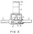
- Fig. 2 shows the structure of each of the first to fourth joints 8, 9, 10, and 11. Since the first to fourth joints 8 to 11 have the same structure, the structure of the first joint 8 is representatively described.
- the first joint 8 is provided with a servomotor 12.
- An electromagnetic lock 14 and decelerators 15 and 16 are mounted on a rotational shaft 13 of the servomotor 12.
- An encoder 17 is coupled to the rotation shaft of the servomotor 12.
- a potentiometer 17a is attached to the encoder 17.
- the second arm 4 is moved in accordance with the rotation of the servomotor 12.
- the third arm 5 is moved.
- the fourth arm 6 is moved when the servomotor attached to the fourth joint 11, the hand 7 is moved.
- fingers 18 are opened and closed.
- the visual sensor 19 is an industrial TV camera.
- the image pickup operation of the visual sensor 19 is controlled by a visual controller 20 or an outside-state recognition controller.
- the visual controller 20 changes the image pickup direction of the visual sensor 19 and keeps the manipulator 1 or an object 21 of the manipulator 1 within the visual field of the visual sensor 19.
- the visual controller 20 outputs image signals of the articulated manipulator 1 or the object 1, based on image processing.
- a display 24 for receiving/outputting data from/to the articulated manipulator 1.
- An input/output controller 25 controls data input/output between the manipulator 1 and the display 24.
- the first to fourth joints 8, 9, 10, and 11 of the articulated manipulator 1 have first to fourth motor controllers 26 to 29.
- the hand 7 has a hand motor controller 30.
- the first to fourth motor controllers 26 to 29 control the servomotors in the respective joints.
- the hand motor controller 30 controls the servomotors in the hand 7.
- the controllers 20 and 25 to 30 are mutually connected by a high-speed communication line 31.
- Fig. 3 shows the structure of the visual controller 20.
- a ROM 33, a RAM 34, an I/O port 35 and a frame memory 38 are connected to a CPU 31 over a bus 32.
- a motor drive circuit 36 is connected to the I/O port 35.
- the motor drive circuit 36 drives a motor 37 to change the image pickup direction of the visual sensor 19.
- An A/D converter circuit 39 is connected to the frame memory 38.
- the A/D converter circuit 39 receives an image signal S from the visual sensor 19.
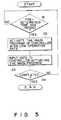
- the ROM 33 stores programs shown in Fig. 4. As is illustrated in Fig. 5, a main program activates a locus calculation program and an interpolation calculation program, and also activates a calculation process shift program at predetermined intervals.
- the locus calculation program is executed to calculate a locus of the articulated manipulator hand 7 from the current position to a target position, on the basis of points located at predetermined intervals.
- the interpolation calculation program is executed to calculate a variation of the angle of each joint of the articulated manipulator 1, between adjacent two of the points of the locus obtained by the locus calculation program.
- the calculation process shift program is executed to detect, at every operation cycle, the controller having the lowest operation rate, among the motor controllers 26 to 29, the hand motor controller 30, the visual controller 20, and the input/output controller 25.
- the controller found to have the lowest operation rate is authorized to perform the locus calculation and interpolation calculation and to detect the controller having the lowest operation rate in the next operation cycle.
- the visual controller 20 delivers an operation on/off signal F to the visual sensor 19 and changes the image pickup direction of the visual sensor 19.
- an image signal stored in the frame memory 38 is sent to the monitor of the display 24 through the high-speed communication line 31 and the input/output controller 25.
- Fig. 6 shows the structure of the input/output controller 25.
- a ROM 42, a RAM 43, an image memory 44 and an I/O 45 are connected to a CPU 49 over a bus 41. Data is input to and output from the display 24 through the I/O 45.
- the ROM 42 stores programs shown in Fig. 7. The main program, the locus calculation program, the interpolation program, and the calculation process shift program have been described above.
- an input/output program transmits image data stored in the image memory 44 to a monitor of the display 24, transmits each angle data to the display 24, and receives an instruction input from the keyboard of the display 24 and transmits the instruction to the controllers 20 and 25 to 30.
- Fig. 8 shows the structure of each motor controller, 26 to 29.
- a ROM 48, a RAM 49, and an I/O port 50 are connected to a CPU 46 over a bus 47.
- a motor drive circuit 51 a limit switch 52, and an electromagnetic lock drive circuit 53 are connected to the I/O port 50.
- the limit switch 52 limits the range of motion of each arm.
- the electromagnetic lock drive circuit 53 drives the electromagnetic lock 14 when it receives a lock command from the CPU 46 or a fault has occurred in the CPU 46.
- the ROM 48 stores programs shown in Fig. 9. The main program, the locus calculation program, the interpolation calculation program and the calculation process shift program have been described above.
- drive control signals representative of drive degree, drive speed and drive direction are generated, which are input to the servomotor 12 in the first joint 8 when the articulated manipulator 1 conveys the object 21.
- drive control signals representative of drive degree, drive speed and drive direction are generated, which are input to the servomotor in the second joint 9 when the articulated manipulator 1 conveys the object 21.
- drive control signals representative of drive degree, drive speed and drive direction are generated, which are input to the servomotor in the third joint 10 when the articulated manipulator 1 conveys the object 21.
- drive control signals representative of drive degree, drive speed and drive direction are generated, which are input to the servomotor in the fourth joint 11 when the articulated manipulator 1 conveys the object 21.
- a fault indication program is executed to output, when a fault occurs in the servomotor, a lock command to the electromagnetic lock 14 and tell the fault to the motor controllers associated with the other servomotors.
- signals representative of the drive degree, drive speed and drive direction, which compensate the function of the servomotor in which a fault occurred, are supplied to the servomotors which normally function.
- a controller fault countermeasure program when a fault occurred in other motor controller, an angle of the malfunctioning servomotor is detected, and signals representative of the drive degree, drive speed and drive direction, which compensate the function of the servomotor in which the fault occurred, are supplied to the servomotors which normally function.
- a drive degree change program is executed to change the drive degree for the servomotors driven by the motor controllers, in accordance with the type of the motors.
- the first to fourth motor controllers 26 to 29 have the same structure.
- Fig. 10 shows the structure of the hand motor controller 30.
- a ROM 56, a RAM 57, and an I/O port 58 are connected to a CPU 54 over a bus 55.
- a motor drive circuit 59 and a limit switch 60 are connected to the I/O port 58.
- the limit switch 60 limits the range of motion of the hand 7 and the fingers 18.
- the ROM 56 stores programs shown in Fig. 11. The main program, the locus calculation program, the interpolation program and the calculation process shift program have been described above.
- a hand control program controls servomotors 61 and 62 provided in the hand 7.
- the servomotor 61 is controlled so as to reduce to zero the departure of the direction of the hand 7 in relation to the position of the object 21.
- the servomotor 62 is controlled so as to open and close the fingers 18 and keep constant the hold force of the fingers 18 with which the object 21 is held.
- the hand motor controller 30 is initially set to activate the main program. Thus, the other controllers do not execute the main program.
- the CPU 31 in the visual controller 20 reads out the visual control program from the ROM 32 and executes this program.
- the CPU 31 starts the operation of the visual sensor 19.
- the visual sensor 19 takes an image of the object 21 and outputs a corresponding image signal.
- the image signal is converted to a digital signal by the A/D converter circuit 39 in the visual controller 20, and the digital signal is stored in the frame memory 38.
- the CPU 31 detects coordinates of an object (object 21 or hand 7 of manipulator 1) based on the digital image signal.
- the CPU 28 directs the visual field of the visual sensor 19 to the detected coordinates.
- the hand motor controller 30 executes the main program and the locus calculation program in parallel processing.
- the CPU 54 of the hand motor controller 30 executes the main program, the CPU 54 detects, after a predetermined time period (step a1 in Fig. 5), the controller 20, 25, 26, 27, 28, 29, or 30 having the lowest operation rate (step a2).
- the operation rate is found by the calculation process shift program.
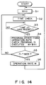
- the CPU 54 sets the operation rate W to zero (step b1 in Fig. 14) and then checks time (step b2). It is determined whether or not a time period ⁇ t has passed (step b3). As shown in Fig. 15, the CPU 54 starts a time check at a time t1 and, after the passing of time period ⁇ t, determines whether any program, other than the operation rate check program, has been executed. If the program, other than the operation rate check program, has been executed, "1" is added to the operation rate W.
- step b5 the CPU 54 determines whether the determination of the execution of other program than the operation rate check program has been done n-times, that is, whether a time period ⁇ tn has passed. If "YES" in step b5, the CPU 54 finds the operation rate W.
- Fig. 15 shows a time period Wa in which the operation rate check program is executed, and a time period Wb in which a program other than the operation rate check program is executed.
- the CPU 54 finds the operation rates of all controllers 20 and 25 to 30.
- the CPU 54 returns to the main program, and detects the controller with lowest operation rate among the controllers 20 and 25 to 30 (step a3). If the detected controller is the hand motor controller 30, the CPU 54 continues to execute the main program, the locus calculation program, and interpolation calculation program.
- the CPU 54 executes the main program and the locus calculation program in parallel.
- step k1 in Fig. 16 the CPU 54 receives target position data from the input/output recognition controller 25.
- step k2 the CPU 54 finds the current position of the hand 7.
- the current position of the hand 7 is calculated from the angles of the joints 8 to 11.
- step k3 the CPU 54 finds a locus of motion of the hand 7 on the basis of the target position and the current position of the hand 7.
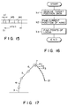
- the locus of motion is described by points P1, P2...set in predetermined time intervals.
- the CPU 54 executes the interpolation calculation program.
- step h1 in Fig. 18 the CPU 54 receives data of points P1, P2...of the locus of motion.
- step h2 the CPU 54 executes interpolation calculation to obtain data of joint angles (rotational angles of servomotors) between points P1 and P2, points P2 and P3, points P3 and P4....
- the CPU 54 sends the data of the joint angles sequentially to the first to fourth motor controllers 26 to 29.
- the first to fourth motor controllers 26 to 29 perform the following operations.
- the CPU 46 in the first motor controller 26 reads out the first motor control program from the ROM 48 and executes this program.
- step y1 in Fig. 19 the CPU 46 receives data of joint angles sequentially.
- step y2 the CPU 46 finds a deviation between the target position data and the angular position data of the servomotor, which is supplied from the encoder 17.
- step y3 the CPU 46 produces drive control signals representative of the drive degree, drive speed and drive direction for the servomotor 12, whereby the deviation is reduced to zero.
- the drive control signals are fed to the motor drive circuit 51.
- the servomotor 12 is driven on the basis of the drive degree, drive speed and drive direction represented by the drive control signals.
- the encoder 17 detects the rotational degree and rotational direction of the servomotor 12 and feeds the data representative of the rotational degree and rotational direction back to the first motor controller 26.
- the output from the encoder 17 is converted by the potentiometer 17a to a signal which is easily processed by the CPU.
- the CPU 46 produces drive control signals so that the deviation between the fed-back data of the rotational degree and rotational direction, on the one hand, and the set data of the rotational degree and rotational direction, on the other, can be reduced to zero.
- the second to fourth motor controllers 27 to 29 control the driving of the servomotors in the joints 9 and 10. In this way, the hand 7 is moved towards the object 21.
- the CPU 46 of the first motor controller 26 reads out the fault indication program from the ROM 48 in every predetermined cycle, and executes this program.
- step j1 in Fig. 20 the CPU 46 receives fed-back data from the encoder. If the fed-back data of drive degree and drive direction has changed, the CPU 46 determines that the servomotor 12 functions normally (step j2). If the fed-back data has not changed, the CPU 46 determines that the servomotor 12 malfunctions. In this case, the CPU 46 informs the controllers 20 and 25 to 30 of the fault of the servomotor 12 (step j5). In step j6, the CPU 46 operates the electromagnetic lock 14 to lock the motion of the first arm 3. At the same time the CPU 46 finds the lock angle of the second arm 4 with respect to the locked first arm 3. The lock angle is calculated from the data of drive degree and drive direction, fed back from the encoder 17.
- the CPU 54 of the hand motor controller 30 executes the main program, locus calculation program, interpolation calculation program and calculation process shift program.
- the CPU 54 executes the motor fault countermeasure program in every predetermined cycle.
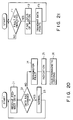
- step r1 in Fig. 21 when the CPU 54 is informed of the fault of the servomotor 12, the CPU 54 finds a locus of motion, along which the hand 7 will be moved to the target position by the operation of the second to fourth joints 9 to 11 (step r2).
- the locus of motion is described by points set at predetermined intervals. The locus of motion varies depending on the lock angle of the second arm 4.
- the CPU 54 sequentially transmits the data of each point to the second and fourth controllers 27 to 29.
- the second and fourth motor controllers 27 to 29 receive the data of each point sequentially. Based on the data of the points, the second and fourth motor controllers 27 to 29 calculate data of drive degree, drive speed and drive direction, whereby the hand 7 is moved to the target position. As a result, the hand 7 is moved towards the object 21 by the operation of the second to fourth joints.
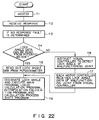
- the CPU in each of the motor controllers 26 to 29 executes the controller fault countermeasure program in every predetermined cycle. In step n1 in Fig. 22, the CPUs access each other. If the CPU of the motor controller 27, 28 or 29 does not receive a response to the access from the controller accessed, this CPU determines a fault in the accessed CPU or a line breakage of the high-speed communication line 31.
- the electromagnetic lock drive circuit 53 detects the fault of the CPU from the aspect of the hardware and drives the electromagnetic lock 14, thereby fixing the joint 9. Also, the fault of the CPU can be detected since it does not output a response to the access from the other CPUs.
- the CPUs of the first, third and fourth motor controllers 26, 28 and 29 determine whether lock angle data can be read out from the potentiometer 17a of the second joint. If the lock angle data can be read out, this data is read out from the encoder of the second joint (step n5).
- step n6 a command is input to the visual controller 20 to detect the lock angle of the second joint.
- the visual controller 20 detects the lock angle of the second joint, on the basis of the image signal and the joint angle data obtained from the first, third and fourth motor controllers 26, 28 and 29, and the visual controller 20 tells the detected lock angle to each motor controller.
- step n7 each motor controller receives the data of the lock angle of the second joint. Once the lock angle is received, the lock angle is fixed and the hand motor controller 30 resets the main program, locus calculation program, interpolation calculation program, and the calculation process shift program.
- the motor controllers 26 to 29 access each other in every predetermined cycle. Based on this access, each controller, 26 to 29, determines the line breakage of the high-speed communication line 31.
- the first controller 26 determines the breakage of the communication line 31 between the first and second motor controllers 26 and 27, the first controller 26 transfers data to the third motor controller 28 (step m3 in Fig. 23). The destination of the transferred data is set to the second motor controller 27. Once the third motor controller 28 receives the data, the data is supplied to the second motor controller 27 in accordance with the set destination of data.
- This invention is also applicable to a manipulator in a nuclear power plant, or to equipment situated in space or in a clean room.
Description
- The present invention relates to a distribution control apparatus for controlling the motion of an articulated manipulator, wherein distribution controllers are provided at the respective joints of the articulated manipulator.
- There is known a distribution control apparatus suitable for an articulated manipulator. The distribution control apparatus comprises a main CPU (Central Processing Unit), a motor control CPU, a communication control CPU, and an I/O (Input/Output) port control CPU. The motor control CPU, the communication control CPU and the I/O port control CPU are subordinate to the main CPU. The main CPU controls the overall operation of the articulated manipulator. The motor control CPU controls servomotors provided at the respective joints of the articulated manipulator. Namely, in the distribution control apparatus, the motor control, communication control, etc. are carried out distributively by corresponding CPUs.
- A program, which is prepared on the basis of the operation of the articulated manipulator, is set in this distribution control apparatus. When the structure of the articulated manipulator is modified, the program must be rewritten and reset.
- In addition, if any one of the CPUs malfunctions, this distribution control apparatus cannot control the articulated manipulator.
- Prior art document EP-A-103 714 discloses a method for operating a computer controlled industrial machine in which a plurality of axes of motion are independently controlled. The method utilizes programmable data processors to enable the production of motion command signals to the servo drives of the machine. Coordinated motion of several axes is attained by programmably grouping axes into motion groups. Each motion group has an assigned master processor which coordinates the operation of all axis processors in that group. The axis processors can be re-assigned to any other motion group while a programmable motion is being performed.
- Further, prior art document EP-A-291 966 describes a control method of a robot system and an apparatus for realizing the same. This robot system has a program module group within a central control unit for performing required program processing, and a plurality of peripheral control modules for controlling the associated portions of the robot. A communication module is provided to perform communication between the modules, and a queue buffer sequentially stores the present status information, a source module name, and the message. The communication module monitors transmission from the respective module, stores a message in the queue buffer, forms a transmit request list, sequentially receives the destination module name and the message in accordance with a reception procedure of the source module, and stores the source name module and the message in the queue buffer in accordance with the destination module. Subsequently, the communication module sequentially searches the message to be transmitted in a queue buffer, and checks the status of the destination modules. If the status of a destination module is set in an enabled state, the message is transmitted in accordance with a transmission procedure of the destination module. If not, the message is left in the queue buffer and will be transmitted in the next transmission cycle.
- It is an object of the present invention to provide a distribution control apparatus capable of efficiently controlling an object to be controlled. Another object of the invention is to provide a distribution control apparatus capable of efficiently controlling an object to be controlled, wherein there is no need to change programs even if the object is changed. Still another object of the invention is to provide a distribution control apparatus capable of continuing to control an object even if a fault occurs.
- To solve this object the present invention provides a distribution control apparatus as specified in
claim 1. - This invention can be more fully understood from the following detailed description when taken in conjunction with the accompanying drawings, in which:
- Fig. 1 shows a distribution control apparatus according to an embodiment of the present invention;
- Fig. 2 shows a structure of a joint;
- Fig. 3 shows a structure of a visual controller;
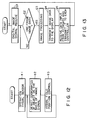
- Fig. 4 shows a ROM structure in the visual controller;
- Fig. 5 is a flowchart for explaining a main program;
- Fig. 6 shows a structure of a input/output controller;
- Fig. 7 shows a ROM structure in the input/output controller;
- Fig. 8 shows a structure of a motor controller;
- Fig. 9 shows a ROM structure in a motor controller;
- Fig. 10 shows a structure of a hand motor controller;
- Fig. 11 shows a ROM structure in the hand motor controller;
- Fig. 12 is a flowchart for explaining a visual control program;
- Fig. 13 is a flowchart for explaining an input/output control program;
- Fig. 14 is a flowchart for explaining a calculation process shift program;
- Fig. 15 is a diagram showing an operation rate calculation period;
- Fig. 16 is a flowchart for explaining a locus calculation program;
- Fig. 17 shows points in a locus of motion;
- Fig. 18 is a flowchart for explaining an interpolation calculation program;
- Fig. 19 is a flowchart for explaining a motor control program;
- Fig. 20 is a flowchart for explaining a fault alarm program;
- Fig. 21 is a flowchart for explaining a motor fault elimination program;
- Fig. 22 is a flowchart for explaining a controller fault elimination program; and
- Fig. 23 is a flowchart for explaining a line-breakage-time data transmission program.
- Embodiments of the present invention will now be described with reference to the accompanying drawings.
- Referring to Fig. 1, an articulated
manipulator 1 is mounted on a base 2. Themanipulator 1 comprises afirst arm 3, asecond arm 4, athird arm 5, anfourth arm 6, and ahand 7. One end portion of thefirst arm 3 is secured to the base 2, and the other end portion of thefirst arm 3 is connected to thesecond arm 4 via afirst joint 8. Thesecond arm 4 is connected to thethird arm 5 via asecond joint 9. Thethird arm 5 is connected to thefourth arm 6 via athird joint 10. Thefourth arm 6 is connected to the hand via a fourth joint 11. - Fig. 2 shows the structure of each of the first to
fourth joints fourth joints 8 to 11 have the same structure, the structure of thefirst joint 8 is representatively described. Thefirst joint 8 is provided with aservomotor 12. Anelectromagnetic lock 14 anddecelerators rotational shaft 13 of theservomotor 12. Anencoder 17 is coupled to the rotation shaft of theservomotor 12. A potentiometer 17a is attached to theencoder 17. Thus, thesecond arm 4 is moved in accordance with the rotation of theservomotor 12. When the servomotor attached to the second joint 9 having the same structure as that of the first joint 8 is rotated, thethird arm 5 is moved. When the servomotor attached to the third joint 10 is rotated, thefourth arm 6 is moved when the servomotor attached to the fourth joint 11, thehand 7 is moved. By the rotation of servomotors provided in thehand 7,fingers 18 are opened and closed. - A
visual sensor 19, which is an outside-state recognition sensor, is arranged above the articulatedmanipulator 1. Thevisual sensor 19 is an industrial TV camera. The image pickup operation of thevisual sensor 19 is controlled by avisual controller 20 or an outside-state recognition controller. Thevisual controller 20 changes the image pickup direction of thevisual sensor 19 and keeps themanipulator 1 or anobject 21 of themanipulator 1 within the visual field of thevisual sensor 19. Thevisual controller 20 outputs image signals of the articulatedmanipulator 1 or theobject 1, based on image processing. - Further, there is provided a
display 24 for receiving/outputting data from/to the articulatedmanipulator 1. An input/output controller 25 controls data input/output between themanipulator 1 and thedisplay 24. - The first to
fourth joints manipulator 1 have first tofourth motor controllers 26 to 29. Thehand 7 has ahand motor controller 30. The first tofourth motor controllers 26 to 29 control the servomotors in the respective joints. Thehand motor controller 30 controls the servomotors in thehand 7. - The
controllers speed communication line 31. - The structures of the
controllers - Fig. 3 shows the structure of the
visual controller 20. AROM 33, aRAM 34, an I/O port 35 and aframe memory 38 are connected to aCPU 31 over abus 32. Amotor drive circuit 36 is connected to the I/O port 35. Themotor drive circuit 36 drives amotor 37 to change the image pickup direction of thevisual sensor 19. An A/D converter circuit 39 is connected to theframe memory 38. The A/D converter circuit 39 receives an image signal S from thevisual sensor 19. TheROM 33 stores programs shown in Fig. 4. As is illustrated in Fig. 5, a main program activates a locus calculation program and an interpolation calculation program, and also activates a calculation process shift program at predetermined intervals. - The locus calculation program is executed to calculate a locus of the articulated
manipulator hand 7 from the current position to a target position, on the basis of points located at predetermined intervals. - The interpolation calculation program is executed to calculate a variation of the angle of each joint of the articulated
manipulator 1, between adjacent two of the points of the locus obtained by the locus calculation program. - The calculation process shift program is executed to detect, at every operation cycle, the controller having the lowest operation rate, among the
motor controllers 26 to 29, thehand motor controller 30, thevisual controller 20, and the input/output controller 25. The controller found to have the lowest operation rate is authorized to perform the locus calculation and interpolation calculation and to detect the controller having the lowest operation rate in the next operation cycle. When the visual control program is executed, thevisual controller 20 delivers an operation on/off signal F to thevisual sensor 19 and changes the image pickup direction of thevisual sensor 19. In addition, when the visual control program is executed, an image signal stored in theframe memory 38 is sent to the monitor of thedisplay 24 through the high-speed communication line 31 and the input/output controller 25. - Fig. 6 shows the structure of the input/
output controller 25. AROM 42, aRAM 43, animage memory 44 and an I/O 45 are connected to aCPU 49 over abus 41. Data is input to and output from thedisplay 24 through the I/O 45. TheROM 42 stores programs shown in Fig. 7. The main program, the locus calculation program, the interpolation program, and the calculation process shift program have been described above. As is shown in Fig. 13, an input/output program transmits image data stored in theimage memory 44 to a monitor of thedisplay 24, transmits each angle data to thedisplay 24, and receives an instruction input from the keyboard of thedisplay 24 and transmits the instruction to thecontrollers - Fig. 8 shows the structure of each motor controller, 26 to 29. A
ROM 48, aRAM 49, and an I/O port 50 are connected to aCPU 46 over abus 47. A motor drive circuit 51 alimit switch 52, and an electromagneticlock drive circuit 53 are connected to the I/O port 50. Thelimit switch 52 limits the range of motion of each arm. The electromagneticlock drive circuit 53 drives theelectromagnetic lock 14 when it receives a lock command from theCPU 46 or a fault has occurred in theCPU 46. TheROM 48 stores programs shown in Fig. 9. The main program, the locus calculation program, the interpolation calculation program and the calculation process shift program have been described above. - Based on a first motor control program, drive control signals representative of drive degree, drive speed and drive direction are generated, which are input to the
servomotor 12 in the first joint 8 when the articulatedmanipulator 1 conveys theobject 21. - Based on a second motor control program, drive control signals representative of drive degree, drive speed and drive direction are generated, which are input to the servomotor in the second joint 9 when the articulated
manipulator 1 conveys theobject 21. - Based on a third motor control program, drive control signals representative of drive degree, drive speed and drive direction are generated, which are input to the servomotor in the third joint 10 when the articulated
manipulator 1 conveys theobject 21. - Based on a fourth motor control program, drive control signals representative of drive degree, drive speed and drive direction are generated, which are input to the servomotor in the fourth joint 11 when the articulated
manipulator 1 conveys theobject 21. - A fault indication program is executed to output, when a fault occurs in the servomotor, a lock command to the
electromagnetic lock 14 and tell the fault to the motor controllers associated with the other servomotors. - According to a motor fault countermeasure program, signals representative of the drive degree, drive speed and drive direction, which compensate the function of the servomotor in which a fault occurred, are supplied to the servomotors which normally function.
- According to a controller fault countermeasure program, when a fault occurred in other motor controller, an angle of the malfunctioning servomotor is detected, and signals representative of the drive degree, drive speed and drive direction, which compensate the function of the servomotor in which the fault occurred, are supplied to the servomotors which normally function.
- According to a line-breakage-time data transmission program, when the high-
speed communication line 31 is broken, data is transmitted through any one of the motor controllers. - A drive degree change program is executed to change the drive degree for the servomotors driven by the motor controllers, in accordance with the type of the motors.
- As has been described above, the first to
fourth motor controllers 26 to 29 have the same structure. - Fig. 10 shows the structure of the
hand motor controller 30. AROM 56, aRAM 57, and an I/O port 58 are connected to aCPU 54 over abus 55. Amotor drive circuit 59 and alimit switch 60 are connected to the I/O port 58. Thelimit switch 60 limits the range of motion of thehand 7 and thefingers 18. TheROM 56 stores programs shown in Fig. 11. The main program, the locus calculation program, the interpolation program and the calculation process shift program have been described above. - A hand control program controls
servomotors hand 7. Theservomotor 61 is controlled so as to reduce to zero the departure of the direction of thehand 7 in relation to the position of theobject 21. Theservomotor 62 is controlled so as to open and close thefingers 18 and keep constant the hold force of thefingers 18 with which theobject 21 is held. - The operation of the apparatus having the above structure will now be described.
- The
hand motor controller 30 is initially set to activate the main program. Thus, the other controllers do not execute the main program. - The
CPU 31 in thevisual controller 20 reads out the visual control program from theROM 32 and executes this program. In step e1 in Fig. 12, theCPU 31 starts the operation of thevisual sensor 19. Thevisual sensor 19 takes an image of theobject 21 and outputs a corresponding image signal. The image signal is converted to a digital signal by the A/D converter circuit 39 in thevisual controller 20, and the digital signal is stored in theframe memory 38. In step e2, theCPU 31 detects coordinates of an object (object 21 orhand 7 of manipulator 1) based on the digital image signal. In the subsequent step e3, theCPU 28 directs the visual field of thevisual sensor 19 to the detected coordinates. - The
hand motor controller 30 executes the main program and the locus calculation program in parallel processing. When theCPU 54 of thehand motor controller 30 executes the main program, theCPU 54 detects, after a predetermined time period (step a1 in Fig. 5), thecontroller - The operation rate is found by the calculation process shift program. The
CPU 54 sets the operation rate W to zero (step b1 in Fig. 14) and then checks time (step b2). It is determined whether or not a time period Δ t has passed (step b3). As shown in Fig. 15, theCPU 54 starts a time check at a time t1 and, after the passing of time period Δ t, determines whether any program, other than the operation rate check program, has been executed. If the program, other than the operation rate check program, has been executed, "1" is added to the operation rate W. In the subsequent step b5, theCPU 54 determines whether the determination of the execution of other program than the operation rate check program has been done n-times, that is, whether a time period Δ tn has passed. If "YES" in step b5, theCPU 54 finds the operation rate W. Fig. 15 shows a time period Wa in which the operation rate check program is executed, and a time period Wb in which a program other than the operation rate check program is executed. TheCPU 54 finds the operation rates of allcontrollers - The
CPU 54 returns to the main program, and detects the controller with lowest operation rate among thecontrollers hand motor controller 30, theCPU 54 continues to execute the main program, the locus calculation program, and interpolation calculation program. - The
CPU 54 executes the main program and the locus calculation program in parallel. - In step k1 in Fig. 16, the
CPU 54 receives target position data from the input/output recognition controller 25. In step k2, theCPU 54 finds the current position of thehand 7. The current position of thehand 7 is calculated from the angles of thejoints 8 to 11. In step k3, theCPU 54 finds a locus of motion of thehand 7 on the basis of the target position and the current position of thehand 7. As is shown in Fig. 17, the locus of motion is described by points P1, P2...set in predetermined time intervals. In addition, theCPU 54 executes the interpolation calculation program. In step h1 in Fig. 18, theCPU 54 receives data of points P1, P2...of the locus of motion. In step h2, theCPU 54 executes interpolation calculation to obtain data of joint angles (rotational angles of servomotors) between points P1 and P2, points P2 and P3, points P3 and P4.... TheCPU 54 sends the data of the joint angles sequentially to the first tofourth motor controllers 26 to 29. - The first to
fourth motor controllers 26 to 29 perform the following operations. TheCPU 46 in thefirst motor controller 26 reads out the first motor control program from theROM 48 and executes this program. In step y1 in Fig. 19, theCPU 46 receives data of joint angles sequentially. In step y2, theCPU 46 finds a deviation between the target position data and the angular position data of the servomotor, which is supplied from theencoder 17. In step y3, theCPU 46 produces drive control signals representative of the drive degree, drive speed and drive direction for theservomotor 12, whereby the deviation is reduced to zero. The drive control signals are fed to themotor drive circuit 51. Thus, theservomotor 12 is driven on the basis of the drive degree, drive speed and drive direction represented by the drive control signals. As has been described above, theencoder 17 detects the rotational degree and rotational direction of theservomotor 12 and feeds the data representative of the rotational degree and rotational direction back to thefirst motor controller 26. The output from theencoder 17 is converted by the potentiometer 17a to a signal which is easily processed by the CPU. Once again, theCPU 46 produces drive control signals so that the deviation between the fed-back data of the rotational degree and rotational direction, on the one hand, and the set data of the rotational degree and rotational direction, on the other, can be reduced to zero. - In like manner, the second to
fourth motor controllers 27 to 29 control the driving of the servomotors in thejoints hand 7 is moved towards theobject 21. - The operation, when a fault has occurred, will now be described.
- Suppose that a fault has occurred in the
servomotor 12 in thefirst joint 8. TheCPU 46 of thefirst motor controller 26 reads out the fault indication program from theROM 48 in every predetermined cycle, and executes this program. In step j1 in Fig. 20, theCPU 46 receives fed-back data from the encoder. If the fed-back data of drive degree and drive direction has changed, theCPU 46 determines that theservomotor 12 functions normally (step j2). If the fed-back data has not changed, theCPU 46 determines that theservomotor 12 malfunctions. In this case, theCPU 46 informs thecontrollers CPU 46 operates theelectromagnetic lock 14 to lock the motion of thefirst arm 3. At the same time theCPU 46 finds the lock angle of thesecond arm 4 with respect to the lockedfirst arm 3. The lock angle is calculated from the data of drive degree and drive direction, fed back from theencoder 17. - As has been described above, the
CPU 54 of thehand motor controller 30 executes the main program, locus calculation program, interpolation calculation program and calculation process shift program. TheCPU 54 executes the motor fault countermeasure program in every predetermined cycle. In step r1 in Fig. 21, when theCPU 54 is informed of the fault of theservomotor 12, theCPU 54 finds a locus of motion, along which thehand 7 will be moved to the target position by the operation of the second tofourth joints 9 to 11 (step r2). As shown in Fig. 17, the locus of motion is described by points set at predetermined intervals. The locus of motion varies depending on the lock angle of thesecond arm 4. In step r3, theCPU 54 sequentially transmits the data of each point to the second andfourth controllers 27 to 29. Thus, the second andfourth motor controllers 27 to 29 receive the data of each point sequentially. Based on the data of the points, the second andfourth motor controllers 27 to 29 calculate data of drive degree, drive speed and drive direction, whereby thehand 7 is moved to the target position. As a result, thehand 7 is moved towards theobject 21 by the operation of the second to fourth joints. - Suppose that a fault has occurred in the
second motor controller 27. - The CPU in each of the
motor controllers 26 to 29 executes the controller fault countermeasure program in every predetermined cycle. In step n1 in Fig. 22, the CPUs access each other. If the CPU of themotor controller speed communication line 31. - When a fault has occurred in the CPU, the electromagnetic
lock drive circuit 53 detects the fault of the CPU from the aspect of the hardware and drives theelectromagnetic lock 14, thereby fixing thejoint 9. Also, the fault of the CPU can be detected since it does not output a response to the access from the other CPUs. When the fault of thesecond motor controller 27 is detected, the CPUs of the first, third andfourth motor controllers second motor controller 27 malfunctions so seriously that the lock angle data cannot be read out from the encoder of the second joint, a command is input to thevisual controller 20 to detect the lock angle of the second joint (step n6). Thevisual controller 20 detects the lock angle of the second joint, on the basis of the image signal and the joint angle data obtained from the first, third andfourth motor controllers visual controller 20 tells the detected lock angle to each motor controller. In step n7, each motor controller receives the data of the lock angle of the second joint. Once the lock angle is received, the lock angle is fixed and thehand motor controller 30 resets the main program, locus calculation program, interpolation calculation program, and the calculation process shift program. - A description will now be given of the case where the high-
speed communication line 31 been broken between the first andsecond motor controllers - As has been described above, the
motor controllers 26 to 29 access each other in every predetermined cycle. Based on this access, each controller, 26 to 29, determines the line breakage of the high-speed communication line 31. When thefirst motor controller 26 determines the breakage of thecommunication line 31 between the first andsecond motor controllers first controller 26 transfers data to the third motor controller 28 (step m3 in Fig. 23). The destination of the transferred data is set to thesecond motor controller 27. Once thethird motor controller 28 receives the data, the data is supplied to thesecond motor controller 27 in accordance with the set destination of data. - This invention is also applicable to a manipulator in a nuclear power plant, or to equipment situated in space or in a clean room.
Claims (12)
- A distribution control apparatus comprising:
a plurality of drive source controllers (26 to 29), arranged at joints of an articulated manipulator, for controlling drive sources which are used to drive said joints; and
a working controller (30), provided at a distal end portion of the articulated manipulator, for controlling a working drive source provided for a working hand;
characterized in that each of said drive source controllers (26 to 29) and said working controller (30) includes:
locus calculation means for calculating a locus of motion of the working hand from the current position thereof to a target position by means of points set at predetermined intervals;
interpolation calculation means for calculating a variation in the angle of a corresponding joint between each adjacent pair of said points; and
calculation process shift means for detecting, in each predetermined period, which one of said drive source controllers (26 to 29) and said working controller (30) has the lowest operation rate during execution of a control operation, wherein the controller detected in one period is authorized to detect a controller having the lowest operation rate, in a subsequent period, among said drive source controllers (26 to 29) and said working controller (30); and the locus calculation means and the interpolation calculation means of the detected controller are operated. - The apparatus according to claim 1, characterized in that:
each of said drive source controllers includes fault detecting/malfunctioning part fixing means, fault countermeasure means, line-breakage-time data transmitting means and drive degree change means;
in the event that a malfunction occurs in one of said drive source controllers (26 to 29) or said drive sources, the fault detecting/malfunctioning part fixing means, associated with the malfunctioning drive source controller or drive source, informs another drive source controller of the occurrence of the malfunction, and makes one of said joints, controlled by the malfunctioning controller or drive source, immovable;
upon being informed from said another drive source controller about the occurrence of the malfunction, the fault countermeasure means of said another drive source controller supplies drive degree data, to compensate for the stoppage of the operation of the malfunctioning controller or drive source, to the drive source controlled by said another drive source controller;
in the event that a communication line connecting said drive source controllers is broken, said line-breakage-time data transmitting means transmits data through one of said drive source controllers; and
said drive degree change means changes the amount of control of a corresponding drive source in accordance with the type of the drive source. - The apparatus according to claim 1, characterized in that said drive sources are servomotors (12).
- The apparatus according to claim 1, characterized in that said drive sources are pulse motors.
- The apparatus according to claim 1, characterized in that said drive sources are actuators.
- The apparatus according to claim 1, characterized in that said working drive source is a servomotor.
- The apparatus according to claim 1, characterized in that said working drive source is a pulse motor.
- The apparatus according to claim 1, characterized in that said working drive source is an actuator.
- The apparatus according to claim 1, characterized in that said calculation process shift means determines a controller having the lowest operation rate on the basis of the ratio of the operation rate calculation time in said period to the time in which at least said locus calculation means and said interpolation calculation means are activated.
- The apparatus according to any one of claims 1 to 9, characterized by
an outside-state recognition sensor (19) for recognizing the outside-state of the articulated manipulator;
an outside-state recognition controller (20) for controlling the operation of the outside-state recognition sensor, and for transmitting data; and
an input/output controller (25) for controlling the input from the outside and the output to the outside. - The apparatus according to claim 10, characterized in that said outside-state recognition sensor is an industrial TV camera.
- The apparatus according to claim 10, characterized in that said outside-state recognition sensor is a solid image-pickup device.
Applications Claiming Priority (4)
| Application Number | Priority Date | Filing Date | Title |
|---|---|---|---|
| JP13885689A JPH033785A (en) | 1989-05-31 | 1989-05-31 | Robot controllor |
| JP138856/89 | 1989-05-31 | ||
| JP130898/90 | 1990-05-21 | ||
| JP13089890A JPH0424803A (en) | 1990-05-21 | 1990-05-21 | Parallel decentralized controller |
Publications (3)
| Publication Number | Publication Date |
|---|---|
| EP0400624A2 EP0400624A2 (en) | 1990-12-05 |
| EP0400624A3 EP0400624A3 (en) | 1991-05-15 |
| EP0400624B1 true EP0400624B1 (en) | 1994-10-26 |
Family
ID=26465892
Family Applications (1)
| Application Number | Title | Priority Date | Filing Date |
|---|---|---|---|
| EP90110293A Expired - Lifetime EP0400624B1 (en) | 1989-05-31 | 1990-05-30 | Distribution control apparatus |
Country Status (3)
| Country | Link |
|---|---|
| US (1) | US5055755A (en) |
| EP (1) | EP0400624B1 (en) |
| DE (1) | DE69013573T2 (en) |
Families Citing this family (36)
| Publication number | Priority date | Publication date | Assignee | Title |
|---|---|---|---|---|
| US5282418A (en) * | 1991-03-13 | 1994-02-01 | Tokyo Kikai Seisakusho, Ltd. | Roller changer |
| DE4202922A1 (en) * | 1992-02-01 | 1993-08-05 | Zeiss Carl Fa | MOTORIC TRIPOD |
| JP2769947B2 (en) * | 1992-05-15 | 1998-06-25 | 株式会社椿本チエイン | Manipulator position / posture control method |
| JP2599571B2 (en) * | 1994-05-11 | 1997-04-09 | ダイトロンテクノロジー株式会社 | Substrate transfer robot |
| US5963712A (en) * | 1996-07-08 | 1999-10-05 | Sony Corporation | Selectively configurable robot apparatus |
| US5757419A (en) * | 1996-12-02 | 1998-05-26 | Qureshi; Iqbal | Inspection method and apparatus for tanks and the like |
| DE19718284C2 (en) * | 1997-05-01 | 2001-09-27 | Kuka Roboter Gmbh | Method and device for monitoring a system with several functional units |
| US6751526B2 (en) * | 1997-08-22 | 2004-06-15 | Sony Corporation | Method for describing robot structure and part of robot |
| JP2000042971A (en) * | 1998-07-29 | 2000-02-15 | Janome Sewing Mach Co Ltd | Horizontal articulated robot |
| US6718533B1 (en) * | 1999-02-26 | 2004-04-06 | Real-Time Innovations, Inc. | Method for building a real-time control system with mode and logical rate |
| US6341246B1 (en) * | 1999-03-26 | 2002-01-22 | Kuka Development Laboratories, Inc. | Object oriented motion system |
| US7882253B2 (en) | 2001-04-05 | 2011-02-01 | Real-Time Innovations, Inc. | Real-time publish-subscribe system |
| JP3643867B2 (en) * | 2001-07-23 | 2005-04-27 | 独立行政法人情報通信研究機構 | Manipulator control method |
| WO2005053912A1 (en) * | 2003-12-01 | 2005-06-16 | Newsouth Innovations Pty Limited | A method for controlling a system formed from interdependent units |
| JP4735795B2 (en) * | 2003-12-26 | 2011-07-27 | 独立行政法人 宇宙航空研究開発機構 | Redundant manipulator control method |
| JP2006013448A (en) * | 2004-05-21 | 2006-01-12 | Matsushita Electric Ind Co Ltd | Line balance control method, line balance controller, and component mounting unit |
| JP4722558B2 (en) * | 2004-06-01 | 2011-07-13 | 株式会社小松製作所 | Die cushion device |
| US7533128B1 (en) | 2005-10-18 | 2009-05-12 | Real-Time Innovations, Inc. | Data distribution service and database management systems bridge |
| US8054752B2 (en) * | 2005-12-22 | 2011-11-08 | Intuitive Surgical Operations, Inc. | Synchronous data communication |
| EP1837131A1 (en) * | 2006-03-20 | 2007-09-26 | Abb Research Ltd. | Manipulator, for example an industrial robot, and drive device for a manipulator |
| EP1844909A1 (en) * | 2006-04-11 | 2007-10-17 | Abb Ab | Multi-input control of an industrial robot system |
| US8671135B1 (en) | 2006-04-24 | 2014-03-11 | Real-Time Innovations, Inc. | Flexible mechanism for implementing the middleware of a data distribution system over multiple transport networks |
| US7827559B1 (en) | 2006-04-24 | 2010-11-02 | Real-Time Innovations, Inc. | Framework for executing multiple threads and sharing resources in a multithreaded computer programming environment |
| US7783853B1 (en) | 2006-04-24 | 2010-08-24 | Real-Time Innovations, Inc. | Memory usage techniques in middleware of a real-time data distribution system |
| CN101089763B (en) * | 2006-06-15 | 2011-01-05 | 上海广茂达伙伴机器人有限公司 | Miniature servo control system based on field base and method |
| CN101219284A (en) * | 2007-01-08 | 2008-07-16 | 鸿富锦精密工业(深圳)有限公司 | Bionic device |
| US7675257B2 (en) * | 2007-03-09 | 2010-03-09 | Regal Beloit Corporation | Methods and systems for recording operating information of an electronically commutated motor |
| KR101305819B1 (en) * | 2012-01-04 | 2013-09-06 | 현대자동차주식회사 | Manipulating intention torque extracting method of wearable robot |
| CN102896631A (en) * | 2012-10-09 | 2013-01-30 | 温州大学 | Real-time/on-line azimuth adjustment device and method |
| JP6700669B2 (en) * | 2015-04-07 | 2020-05-27 | キヤノン株式会社 | Control method, robot device, program, recording medium, and article manufacturing method |
| CN106041935A (en) * | 2016-07-27 | 2016-10-26 | 重庆峰创科技有限公司 | High-reliability fault-tolerant control device for an industrial robot |
| GB201713277D0 (en) * | 2017-08-18 | 2017-10-04 | Rolls Royce Plc | Hyper-redundant manipulators |
| CN108247620A (en) * | 2018-01-22 | 2018-07-06 | 东莞市精联精密技术有限公司 | A kind of micron order commercial measurement quality inspection mechanical arm and its detection method |
| CN109909646B (en) * | 2019-02-02 | 2021-01-01 | 宁波吉利汽车研究开发有限公司 | Method and device for correcting working point of robot welding gun and electronic equipment |
| US11433534B2 (en) * | 2019-03-07 | 2022-09-06 | Abb Schweiz Ag | Robotic arm including edge computer and cabling arrangement facilitating flexible function advanced distal arm end tooling |
| EP4219092A1 (en) * | 2022-01-28 | 2023-08-02 | Kassow Robots ApS | Optimized safety architecture in a robot |
Citations (1)
| Publication number | Priority date | Publication date | Assignee | Title |
|---|---|---|---|---|
| EP0291966A1 (en) * | 1987-05-21 | 1988-11-23 | Kabushiki Kaisha Toshiba | Control method of a robot system and apparatus for realizing the same |
Family Cites Families (18)
| Publication number | Priority date | Publication date | Assignee | Title |
|---|---|---|---|---|
| FR2377251A1 (en) * | 1977-01-12 | 1978-08-11 | Line Sa | NC and cNC machine tool control system - with tool head movements resolved along three axes and head speeds reduced accordingly |
| US4221997A (en) * | 1978-12-18 | 1980-09-09 | Western Electric Company, Incorporated | Articulated robot arm and method of moving same |
| US4467436A (en) * | 1981-10-26 | 1984-08-21 | United States Robots, Inc. | Robot arm controller with common bus memory |
| JPS5927307A (en) * | 1982-08-04 | 1984-02-13 | Hitachi Ltd | Method and device for controlling path |
| US4514814A (en) * | 1982-09-07 | 1985-04-30 | General Electric Company | Multi-processor axis control |
| JPS59114609A (en) * | 1982-12-22 | 1984-07-02 | Hitachi Ltd | Method and device for controlling robot |
| JPS59218513A (en) * | 1983-05-26 | 1984-12-08 | Fanuc Ltd | Arc control method of industrial robot |
| US4547858A (en) * | 1983-06-13 | 1985-10-15 | Allied Corporation | Dynamic control for manipulator |
| US4617502A (en) * | 1983-06-30 | 1986-10-14 | Hitachi, Ltd. | Method and apparatus for controlling a robot hand along a predetermined path |
| JPS6085885A (en) * | 1983-10-17 | 1985-05-15 | 株式会社日立製作所 | Controller for multi-joint mechanism |
| JPS60193016A (en) * | 1984-03-14 | 1985-10-01 | Toyota Motor Corp | Robot device |
| DE3501968A1 (en) * | 1985-01-22 | 1986-07-24 | Siemens AG, 1000 Berlin und 8000 München | CONTROL DEVICE FOR A MULTI-AXIS MACHINE |
| US4663726A (en) * | 1985-04-15 | 1987-05-05 | General Electric Co. | Robot control utilizing cubic spline interpolation |
| JPS62232006A (en) * | 1986-04-02 | 1987-10-12 | Yokogawa Electric Corp | Robot system |
| JP2713899B2 (en) * | 1987-03-30 | 1998-02-16 | 株式会社日立製作所 | Robot equipment |
| JPH0820894B2 (en) * | 1987-07-01 | 1996-03-04 | 株式会社日立製作所 | Industrial robot operation control method |
| JP2719345B2 (en) * | 1988-03-30 | 1998-02-25 | 豊田工機株式会社 | Processing control device using force sensor |
| US4878002A (en) * | 1988-10-27 | 1989-10-31 | Advanced Engineering Systems, Operations & Products, Inc. | Multi-axis DSP-based parallel processing servo controller for machine tools and robots |
-
1990
- 1990-05-29 US US07/529,571 patent/US5055755A/en not_active Expired - Fee Related
- 1990-05-30 DE DE69013573T patent/DE69013573T2/en not_active Expired - Fee Related
- 1990-05-30 EP EP90110293A patent/EP0400624B1/en not_active Expired - Lifetime
Patent Citations (1)
| Publication number | Priority date | Publication date | Assignee | Title |
|---|---|---|---|---|
| EP0291966A1 (en) * | 1987-05-21 | 1988-11-23 | Kabushiki Kaisha Toshiba | Control method of a robot system and apparatus for realizing the same |
Also Published As
| Publication number | Publication date |
|---|---|
| DE69013573D1 (en) | 1994-12-01 |
| EP0400624A3 (en) | 1991-05-15 |
| DE69013573T2 (en) | 1995-03-16 |
| US5055755A (en) | 1991-10-08 |
| EP0400624A2 (en) | 1990-12-05 |
Similar Documents
| Publication | Publication Date | Title |
|---|---|---|
| EP0400624B1 (en) | Distribution control apparatus | |
| US4833624A (en) | Functioning-distributed robot control system | |
| US4621332A (en) | Method and apparatus for controlling a robot utilizing force, position, velocity, spring constant, mass coefficient, and viscosity coefficient | |
| US5834916A (en) | Industrial robot and its control unit | |
| US5047701A (en) | Manipulator | |
| JP5916716B2 (en) | Method for controlling an automated work cell | |
| US8761932B2 (en) | Automation equipment control system | |
| EP0260326B1 (en) | Robot controller | |
| EP0927612B1 (en) | Robot controller | |
| JP5847164B2 (en) | Method for controlling an automated work cell | |
| US4763055A (en) | Digital robot control having high performance servo control system | |
| Zielinski | The MRROC++ system | |
| KR20170100028A (en) | Manipulator system for the coordinated control of at least two manipulators | |
| EP0465661B1 (en) | Method and apparatus for controlling an articulated robot having redundancy | |
| US6711468B2 (en) | Control system for robots | |
| JPH0789293B2 (en) | Arm control device | |
| JP3269004B2 (en) | Robot controller | |
| EP0271590B1 (en) | Robot control apparatus | |
| EP0269373A2 (en) | Multiaxis robot control having protection system with energy and backup velocity monitoring | |
| Caccavale et al. | RePLiCS: An environment for open real-time control of a dual-arm industrial robotic cell based on RTAI-Linux | |
| Bejczy et al. | A synchronized computational architecture for generalized bilateral control of robot arms | |
| WO2021193905A1 (en) | Robot system control method | |
| Corke | High-performance visual servoing for robot end-point control | |
| JP3136172B2 (en) | Master-slave manipulator | |
| Marton | Distributed controller architecture for advanced robot control |
Legal Events
| Date | Code | Title | Description |
|---|---|---|---|
| PUAI | Public reference made under article 153(3) epc to a published international application that has entered the european phase |
Free format text: ORIGINAL CODE: 0009012 |
|
| 17P | Request for examination filed |
Effective date: 19900627 |
|
| AK | Designated contracting states |
Kind code of ref document: A2 Designated state(s): DE FR GB |
|
| PUAL | Search report despatched |
Free format text: ORIGINAL CODE: 0009013 |
|
| AK | Designated contracting states |
Kind code of ref document: A3 Designated state(s): DE FR GB |
|
| 17Q | First examination report despatched |
Effective date: 19930607 |
|
| GRAA | (expected) grant |
Free format text: ORIGINAL CODE: 0009210 |
|
| AK | Designated contracting states |
Kind code of ref document: B1 Designated state(s): DE FR GB |
|
| REF | Corresponds to: |
Ref document number: 69013573 Country of ref document: DE Date of ref document: 19941201 |
|
| ET | Fr: translation filed | ||
| PLBE | No opposition filed within time limit |
Free format text: ORIGINAL CODE: 0009261 |
|
| STAA | Information on the status of an ep patent application or granted ep patent |
Free format text: STATUS: NO OPPOSITION FILED WITHIN TIME LIMIT |
|
| 26N | No opposition filed | ||
| REG | Reference to a national code |
Ref country code: GB Ref legal event code: 746 Effective date: 19981012 |
|
| REG | Reference to a national code |
Ref country code: FR Ref legal event code: D6 |
|
| PGFP | Annual fee paid to national office [announced via postgrant information from national office to epo] |
Ref country code: FR Payment date: 20000510 Year of fee payment: 11 |
|
| PGFP | Annual fee paid to national office [announced via postgrant information from national office to epo] |
Ref country code: GB Payment date: 20000524 Year of fee payment: 11 |
|
| PGFP | Annual fee paid to national office [announced via postgrant information from national office to epo] |
Ref country code: DE Payment date: 20000529 Year of fee payment: 11 |
|
| PG25 | Lapsed in a contracting state [announced via postgrant information from national office to epo] |
Ref country code: GB Free format text: LAPSE BECAUSE OF NON-PAYMENT OF DUE FEES Effective date: 20010530 |
|
| GBPC | Gb: european patent ceased through non-payment of renewal fee |
Effective date: 20010530 |
|
| PG25 | Lapsed in a contracting state [announced via postgrant information from national office to epo] |
Ref country code: FR Free format text: LAPSE BECAUSE OF NON-PAYMENT OF DUE FEES Effective date: 20020131 |
|
| PG25 | Lapsed in a contracting state [announced via postgrant information from national office to epo] |
Ref country code: DE Free format text: LAPSE BECAUSE OF NON-PAYMENT OF DUE FEES Effective date: 20020301 |