EP0400482A2 - Microvalve - Google Patents
Microvalve Download PDFInfo
- Publication number
- EP0400482A2 EP0400482A2 EP90109887A EP90109887A EP0400482A2 EP 0400482 A2 EP0400482 A2 EP 0400482A2 EP 90109887 A EP90109887 A EP 90109887A EP 90109887 A EP90109887 A EP 90109887A EP 0400482 A2 EP0400482 A2 EP 0400482A2
- Authority
- EP
- European Patent Office
- Prior art keywords
- valve
- electrodes
- plate
- plates
- openings
- Prior art date
- Legal status (The legal status is an assumption and is not a legal conclusion. Google has not performed a legal analysis and makes no representation as to the accuracy of the status listed.)
- Granted
Links
- 239000004033 plastic Substances 0.000 claims description 18
- 229920003023 plastic Polymers 0.000 claims description 18
- 238000004519 manufacturing process Methods 0.000 claims description 15
- 238000006073 displacement reaction Methods 0.000 claims description 11
- 239000002184 metal Substances 0.000 claims description 11
- 229910052751 metal Inorganic materials 0.000 claims description 11
- 238000000034 method Methods 0.000 claims description 11
- 238000010137 moulding (plastic) Methods 0.000 claims description 6
- 238000001459 lithography Methods 0.000 claims description 5
- 239000002966 varnish Substances 0.000 claims description 3
- 239000012777 electrically insulating material Substances 0.000 claims 1
- 239000004922 lacquer Substances 0.000 claims 1
- 238000005498 polishing Methods 0.000 claims 1
- 239000003990 capacitor Substances 0.000 description 3
- 239000004020 conductor Substances 0.000 description 3
- 238000001015 X-ray lithography Methods 0.000 description 2
- 230000004913 activation Effects 0.000 description 2
- 238000005516 engineering process Methods 0.000 description 2
- 239000000463 material Substances 0.000 description 2
- 229920000642 polymer Polymers 0.000 description 2
- 230000006978 adaptation Effects 0.000 description 1
- 239000002131 composite material Substances 0.000 description 1
- 238000010586 diagram Methods 0.000 description 1
- 238000005323 electroforming Methods 0.000 description 1
- 150000002739 metals Chemical class 0.000 description 1
- 238000000926 separation method Methods 0.000 description 1
- 230000001360 synchronised effect Effects 0.000 description 1
- 230000005469 synchrotron radiation Effects 0.000 description 1
Images
Classifications
-
- F—MECHANICAL ENGINEERING; LIGHTING; HEATING; WEAPONS; BLASTING
- F16—ENGINEERING ELEMENTS AND UNITS; GENERAL MEASURES FOR PRODUCING AND MAINTAINING EFFECTIVE FUNCTIONING OF MACHINES OR INSTALLATIONS; THERMAL INSULATION IN GENERAL
- F16K—VALVES; TAPS; COCKS; ACTUATING-FLOATS; DEVICES FOR VENTING OR AERATING
- F16K31/00—Actuating devices; Operating means; Releasing devices
- F16K31/02—Actuating devices; Operating means; Releasing devices electric; magnetic
-
- B—PERFORMING OPERATIONS; TRANSPORTING
- B65—CONVEYING; PACKING; STORING; HANDLING THIN OR FILAMENTARY MATERIAL
- B65D—CONTAINERS FOR STORAGE OR TRANSPORT OF ARTICLES OR MATERIALS, e.g. BAGS, BARRELS, BOTTLES, BOXES, CANS, CARTONS, CRATES, DRUMS, JARS, TANKS, HOPPERS, FORWARDING CONTAINERS; ACCESSORIES, CLOSURES, OR FITTINGS THEREFOR; PACKAGING ELEMENTS; PACKAGES
- B65D90/00—Component parts, details or accessories for large containers
- B65D90/54—Gates or closures
- B65D90/58—Gates or closures having closure members sliding in the plane of the opening
- B65D90/587—Gates or closures having closure members sliding in the plane of the opening having a linear motion
-
- B—PERFORMING OPERATIONS; TRANSPORTING
- B65—CONVEYING; PACKING; STORING; HANDLING THIN OR FILAMENTARY MATERIAL
- B65D—CONTAINERS FOR STORAGE OR TRANSPORT OF ARTICLES OR MATERIALS, e.g. BAGS, BARRELS, BOTTLES, BOXES, CANS, CARTONS, CRATES, DRUMS, JARS, TANKS, HOPPERS, FORWARDING CONTAINERS; ACCESSORIES, CLOSURES, OR FITTINGS THEREFOR; PACKAGING ELEMENTS; PACKAGES
- B65D90/00—Component parts, details or accessories for large containers
- B65D90/54—Gates or closures
- B65D90/58—Gates or closures having closure members sliding in the plane of the opening
- B65D90/60—Gates or closures having closure members sliding in the plane of the opening and having one or more openings
-
- F—MECHANICAL ENGINEERING; LIGHTING; HEATING; WEAPONS; BLASTING
- F16—ENGINEERING ELEMENTS AND UNITS; GENERAL MEASURES FOR PRODUCING AND MAINTAINING EFFECTIVE FUNCTIONING OF MACHINES OR INSTALLATIONS; THERMAL INSULATION IN GENERAL
- F16K—VALVES; TAPS; COCKS; ACTUATING-FLOATS; DEVICES FOR VENTING OR AERATING
- F16K3/00—Gate valves or sliding valves, i.e. cut-off apparatus with closing members having a sliding movement along the seat for opening and closing
- F16K3/02—Gate valves or sliding valves, i.e. cut-off apparatus with closing members having a sliding movement along the seat for opening and closing with flat sealing faces; Packings therefor
- F16K3/0254—Gate valves or sliding valves, i.e. cut-off apparatus with closing members having a sliding movement along the seat for opening and closing with flat sealing faces; Packings therefor being operated by particular means
-
- F—MECHANICAL ENGINEERING; LIGHTING; HEATING; WEAPONS; BLASTING
- F16—ENGINEERING ELEMENTS AND UNITS; GENERAL MEASURES FOR PRODUCING AND MAINTAINING EFFECTIVE FUNCTIONING OF MACHINES OR INSTALLATIONS; THERMAL INSULATION IN GENERAL
- F16K—VALVES; TAPS; COCKS; ACTUATING-FLOATS; DEVICES FOR VENTING OR AERATING
- F16K99/00—Subject matter not provided for in other groups of this subclass
- F16K99/0001—Microvalves
- F16K99/0003—Constructional types of microvalves; Details of the cutting-off member
- F16K99/0011—Gate valves or sliding valves
-
- F—MECHANICAL ENGINEERING; LIGHTING; HEATING; WEAPONS; BLASTING
- F16—ENGINEERING ELEMENTS AND UNITS; GENERAL MEASURES FOR PRODUCING AND MAINTAINING EFFECTIVE FUNCTIONING OF MACHINES OR INSTALLATIONS; THERMAL INSULATION IN GENERAL
- F16K—VALVES; TAPS; COCKS; ACTUATING-FLOATS; DEVICES FOR VENTING OR AERATING
- F16K99/00—Subject matter not provided for in other groups of this subclass
- F16K99/0001—Microvalves
- F16K99/0034—Operating means specially adapted for microvalves
- F16K99/0042—Electric operating means therefor
- F16K99/0051—Electric operating means therefor using electrostatic means
-
- Y—GENERAL TAGGING OF NEW TECHNOLOGICAL DEVELOPMENTS; GENERAL TAGGING OF CROSS-SECTIONAL TECHNOLOGIES SPANNING OVER SEVERAL SECTIONS OF THE IPC; TECHNICAL SUBJECTS COVERED BY FORMER USPC CROSS-REFERENCE ART COLLECTIONS [XRACs] AND DIGESTS
- Y10—TECHNICAL SUBJECTS COVERED BY FORMER USPC
- Y10T—TECHNICAL SUBJECTS COVERED BY FORMER US CLASSIFICATION
- Y10T137/00—Fluid handling
- Y10T137/8593—Systems
- Y10T137/86493—Multi-way valve unit
- Y10T137/86718—Dividing into parallel flow paths with recombining
- Y10T137/86759—Reciprocating
Definitions
- the invention relates to a microvalve and a method for its production.
- valves which due to their small moving mass and short travel ranges have extremely short switching times, low wear and low power consumption of their actuators.
- Micro valves whose valve structures can have dimensions down to the micrometer range, are also characterized by a low internal and dead volume and the possibility of high-precision metering.
- microvalves are equipped with conventional electromagnetic actuators, there are limits to miniaturization, which are due to difficulties in the assembly of macroscopic components based on microtechnologically generated structures. Therefore microvalves have already been considered which are equipped with a piezoelectric or magnetostrictive actuator or a bimetallic actuator.
- the object of the invention is to provide a microvalve with low drive power, high controllable throughput, streamlined geometry and short switching times, which combines the advantages of efficient production and assembly in mass production technology, and to provide a method for producing such a microvalve.
- the microvalve according to the invention has an electrostatic drive.
- the electrostatic drive can be integrated with or in the valve plates.
- the electrodes are formed on the valve plates themselves, whereby they can be combined in various ways with the preferably slit-shaped valve openings.
- the valve plates preferably each have a plurality of slit-shaped valve openings.
- the actuating force that can be achieved by the electrostatic drive depends on the number of interacting electrodes and their length perpendicular to the direction of movement.
- the opposite electrodes form a capacitor of variable capacitance. In the preferred embodiments, as many electrode edges interacting as possible are therefore formed in an available total electrode area.
- the permissible control potentials, at which no flashover occurs between the electrodes, can be increased to values in the range of over 200 V by interposing an insulating layer, even if the electrodes are in sliding contact with one another via a very thin insulating layer, for example 1 ⁇ m thick.
- the insulating layer is preferably made of a material that ensures low sliding friction.
- the microvalve according to the invention is also characterized by a particularly small space requirement.
- One is in particular very flat design possible, since the valve plates can be made flat and, in addition to the valve plates, only a housing accommodating them is required, in which the flow channels for the medium to be controlled can be arranged such that the flow is not deflected.
- microvalve according to the invention is that the dimensioning of the drive can be selected independently of the valve openings, so that an adaptation to different requirements with regard to the media pressures and flow rates to be controlled is easily possible.
- the electrodes of each valve plate are divided into several groups which are offset from one another by an amount that is a fraction of the distance between adjacent electrodes in each Group is. Furthermore, the electrodes of the different groups are electrically insulated from one another, so that they can be activated by different activation potentials and can be activated at different times.
- this design prevents the valve plates from remaining in a dead center position when their strip-shaped electrodes are exactly opposite one another; on the other hand, by controlling the valve plates by means of suitable alternating rectangular potentials, it is possible to control the direction of movement and a step-wise switching in several switching stages, the desired number of switching steps being able to be achieved by means of several groups of separately controllable electrodes.
- X-ray depth lithography is a technique that is known from KfK News Volume 19 4/87, pp. 167-179 and is well suited for the production of a microvalve, because the finest structures with structural walls that are almost parallel to the direction of irradiation can be produced over sufficient layer thicknesses.
- Deep X-ray lithography is carried out with synchrotron radiation. First, a primary plastic mold is created, which is then galvanically filled with a metal. The resulting metal structure is then used as a mold insert for the production of secondary plastic molds that are used in mass production le of the primary plastic form. This procedure opens up the mass production of the finest microvalve structures, in particular for the microvalve described above.
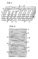
- the microvalve contains three valve plates: two mechanically connected, fixed valve plates 10, 12 and a movable valve plate 14 arranged between them
- Valve plates 10, 12 can also be referred to as “stator valve plates” and the valve plate 14 as “rotor valve plate”.
- valve plates 10, 12 and 14 are provided with three slit-shaped valve openings 16.
- the valve openings 16 extend in a straight line perpendicular to the direction of the relative displacement between the valve plates; this direction is illustrated in Fig. 1 by a double arrow. All valve openings 16 have the same width and the same distance from the respectively adjacent valve opening. The distance between adjacent valve openings 16 is slightly larger than the width of the valve openings.
- Fig. 1 the valve plates 10, 12 and 14 are shown in an intermediate position, in which the separating webs 18 located between the valve openings 16 of the valve plate 14 partially close the flow gap formed by the valve openings 16 of the valve plates 10, 12.
- the valve plate 14 is movable between an open position in which the valve openings of all valve plates are aligned with one another and a closed position in which the webs 18 of the valve plate 14 close the valve openings 16 of the valve plates 10, 12.
- the actuating forces for displacing the valve plate 14 are provided by an electrostatic drive.
- This electrostatic drive is integrated in the valve plates 10, 12, 14. It consists of strip-shaped electrodes which are arranged at least on the mutually facing surfaces of the valve plates 10, 12, 14 at equal distances from one another parallel to the valve openings 16 with a pitch which corresponds to the pitch of the valve openings 16.
- valve plates 10, 12 and 14 consist of a non-conductive plastic. Corresponding in the electrodes of the valve plates Galvanic metal is deposited in between.
- the electrodes are shown hatched in FIG. 1 and designated with the reference number 20 on one side of the valve openings 16 and 22 on the other side.
- the electrodes 20, 22 extend through the entire thickness of the valve plates 10, 12, 14. At their ends they are each electrically connected to one another by a conductor track 24.
- valve plates 10, 12, 14 are arranged at a small distance of at most a few ⁇ m from one another if particularly low friction losses are desired.
- at least one insulating layer is inserted between each two valve plates, which increases the dielectric strength, so that increased control potentials can be applied to the electrodes 20, 22. Insulating layers are available that have the desired high dielectric strength and dielectric constant as well as high wear resistance and low sliding friction on each other.
- the opposite electrodes 20 and 22 of the valve plates 10, 12, 14 each form a capacitor. Forces exist between the electrodes of each capacitor, the direction and size of which depend on the potentials applied to the electrodes.
- the strip-shaped electrodes 20, 22 of the valve plate 14 are offset relative to those of the valve plates 10, 12 in the direction of the relative displacement. If the same electrical control potential is now applied to the electrodes 20, 22 of the valve plates 10, 12 and an opposite electrical control potential is applied to the electrodes, the result is a counter-current between them overlying electrodes attraction forces with force components in the direction of the relative displacement and force components perpendicular to this direction.
- the forces oriented perpendicular to the direction of the relative displacement are equally large on both sides of the valve plate 14, but directed in opposite directions, so that they largely compensate for one another.
- the resulting forces act solely in the direction of the relative displacement and cause the valve plate 14 to move into the open position, in which all valve openings 16 are aligned with one another.
- valve plate 14 moves in the opposite direction into the closed position, in which the separating webs 18 block the passage of the valve openings 16.
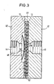
- Fig. 2 shows a complete valve plate in plan view. From Fig. 2 it can be seen that the area of the strip-shaped electrodes 20, 22 is a multiple of the area of the two valve openings 16. Since the actuating forces that can be generated are the sum of the forces generated by each individual electrode, the actuating force that is suitable for the respective requirements can be set via the number of electrodes, it being assumed that equally large control potentials are created in which a flashover between the electrodes certainly does not occur. It is also readily apparent that the actuating force generated is proportional to the length of the strip-shaped electrodes, so that a further variation possibility is to appropriately dimension the length of the strip-shaped electrodes.
- the ends of the strip-shaped electrodes 20, 22 are connected to a connecting frame 32 which surrounds the entire structure and which is on one side of the rectangular shape of the valve plate is continued via an extension 34 to an edge.
- Contact can be made at this edge, for example by means of a contact spring or a contact grinder.
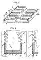
- Fig. 3 shows a complete microvalve with valve plates of the type shown in Figs. 1 and 2, which are received in a recess of a housing consisting of two parts 40, 42.
- the three valve plates are identified with the reference numerals 10, 12 and 14 analogously to FIG. 1.
- the respective number of valve openings and their geometric shape as well as the number and arrangement of electrodes can be adapted to the respective application of the valve, i.e. Throughput and pressure to be created, can be optimally adjusted.
- the two housing parts 40, 42 have flow channels 44, 46 which are in alignment with one another and which open out opposite the valve openings 16 into a recess 49 which is located in the part 42 and in which the valve plates 10, 12, 14 are received.
- the valve plates 10, 12, 14 are held against one another under slight prestress by a curved leaf spring 50, which is supported on the one hand on a wall of a recess 48 of the part 40 and on the other hand on the outer surface of the valve plate 10.
- the electrodes of the various valve plates 10, 12, 14 are contacted in the region of the lateral edges of these valve plates, designated 52.
- a rotor valve plate 60 is combined with a stator valve plate 62, which consists of a base plate 62A and an electrode plate 62B placed thereon. Recesses are formed in the electrode plate 62B, in which lateral projections 60A, 60B of the rotor valve plate 60 are slidably received.
- the projections 60A, 60B and the corresponding ones are on the surfaces opposite one another and parallel to the direction of displacement indicated by a double arrow Parts of the electrode plate 62B are provided with electrodes which are comb-shaped in plan view in accordance with FIG. 5.
- Each projection of the comb structure forms an electrode at its front end. The separation between adjacent electrodes is created by the space between adjacent projections of the comb structure.
- the electrode structures form on the one hand two groups, which are located mirror-symmetrically on both sides of the slit-shaped valve openings 16, and on the other hand a number of groups on each side of the valve openings. Furthermore, it can be seen that several sets of these valve openings are present in pairs in the longitudinal direction of the valve openings 16. Guide strips 64 are assigned to the runner valve plate 60, which keep the lateral edges at the free end of the extension 60A or 60B at a constant and well-defined distance from the opposite walls of the electrode plate 62B.
- the electrode plate 62B and the valve plate 60 consist of metal which has been galvanically embedded in the intermediate forms of a plastic mold. At least one insulating layer is preferably arranged between the electrode plate 62B and the valve plate 60, in a similar manner to the embodiment according to FIG. 1.
- the process according to the invention for the production of microvalves of the type described above makes use of the process steps X-ray depth lithography, electroforming and plastic molding, which are referred to collectively as the LIGA process and are described in detail in the KFK-Nachzin, volume 19 4/87, pages 167-179 .
- the LIGA process enables the production of high-precision microstructures from plastics, metals or structures from a metal / plastic composite.
- Valve plate blanks are arranged on an electrically conductive base plate, which have been provided with free or recessed areas by X-ray lithography or plastic molding, which correspond to the valve openings and the electrode structures.
- Valve openings are then sealed with a varnish, which is easily soluble compared to the plastic material of the valve plate blank, or with wax.
- the remaining free areas corresponding to the electrode structures are then galvanically filled with a metal.
- the surface of the valve plate blanks is polished.
- the valve openings are then exposed again.
- the polished surface is provided with an insulating layer. The valve plate thus finished can then be mounted in a housing together with the required further valve plates.
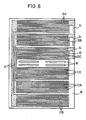
- the electrodes are arranged in three groups 20A / 22A, 20B / 22B, 20C / 22C, which are electrically separated from one another.
- the electrode groups 20A, 20B, 20C are arranged on one side of the valve openings 16, the electrode groups 22A, 22B, 22C on the other side of the valve openings. Electrodes of the same group are electrically connected to one another via conductor tracks 32.
- the conductor tracks are led over lugs 34 to the edge of the valve plate, where contact can be made, for example, with a contact spring or a contact grinder.
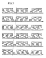
- the control of the individual electrode groups by means of suitable control potentials is explained in FIG. 7 using the example of an embodiment which is derived from that according to FIGS. 4 and 5.
- Fig. 7 three electrode groups of a fixed valve plate and the electrodes of a movable valve plate are shown in different control states. For reasons of illustration technology, only three electrodes are drawn per electrode group. The individual electrode groups are shifted from each other by 1/3 of the electrode division and can be individually applied with control potentials. The signs of the applied control potentials are indicated on the respective electrodes. The moving The valve plate with its electrodes is at a constant, positive potential. The control potential at the fixed electrode groups can be switched separately between positive and negative potential for each group. The first case shown in FIG. 7 corresponds to negative potential at the left fixed electrode group and positive potential at the other two groups.
- the movable valve plate tends to align itself with the fixed valve plate in such a way that the electrodes of the movable plate and the electrodes of the left-hand electrode group of the fixed valve plate face each other in alignment.
- this state is approximately reached.
- the electrodes of the movable and the electrodes of the left group of the fixed valve plate are aligned.
- the control potential on the left electrode group is now positive, instead a negative potential is applied on the right electrode group. This causes the movable valve plate to align with the electrodes of the right group and thus further movement to the left, as shown in case four.
- the rectangular valve plates have a size of 20 ⁇ 15 mm 2, for example, and there are 900 electrodes 14 mm long and 10 ⁇ m wide on each valve plate.
- a positioning force of 2.4 N can be generated in the embodiments with one electrode group and 0.8 N in embodiments with three electrode groups.
- the movable valve plate can be reset by an external return element, for example a return spring.
- the electrode groups of the fixed valve plate are each offset by 6.67 ⁇ m and are driven by phase-shifted square-wave voltages.
- valve openings and flow paths are assigned to one another in a suitable manner.
Abstract
Description
Die Erfindung betrifft ein Mikroventil und ein Verfahren zu seiner Herstellung.The invention relates to a microvalve and a method for its production.
Die Miniaturisierung von Ventilen hat zur Entwicklung von Mikroventilen geführt, die aufgrund ihrer geringen bewegten Masse und kleinen Stellwege extrem kurze Schaltzeiten, einen geringen Verschleiß und eine geringe Leistungsaufnahme ihres Antriebs aufweisen. Mikroventile, deren Ventilstrukturen Abmessungen bis herab in den Mikrometerbereich aufweisen können, zeichnen sich ferner durch geringes Innen- und Totvolumen und die Möglichkeit einer hochgenauen Dosierung aus.The miniaturization of valves has led to the development of microvalves, which due to their small moving mass and short travel ranges have extremely short switching times, low wear and low power consumption of their actuators. Micro valves, whose valve structures can have dimensions down to the micrometer range, are also characterized by a low internal and dead volume and the possibility of high-precision metering.
Solange derartige Mikroventile mit herkömmlichen elektromagnetischen Antrieben ausgestattet werden, sind der Miniaturisierung Grenzen gesetzt, die durch Schwierigkeiten bei der Montage makroskopischer Bauteile auf mikrotechnisch erzeugten Strukturen beruhen. Es wurden daher bereits Mikroventile in Betracht gezogen, die mit piezoelektrischem oder magnetostriktivem Antrieb oder Bimetallantrieb ausgestattet sind.As long as such microvalves are equipped with conventional electromagnetic actuators, there are limits to miniaturization, which are due to difficulties in the assembly of macroscopic components based on microtechnologically generated structures. Therefore microvalves have already been considered which are equipped with a piezoelectric or magnetostrictive actuator or a bimetallic actuator.
Auch bei diesen Antriebskonzepten bereitet jedoch die Montage des Antriebs mit den Ventilstrukturen erhebliche Schwierigkeiten, die der angestrebten kostengünstigen Massenfertigung im Wege stehen.Even with these drive concepts, however, the assembly of the drive with the valve structures presents considerable difficulties which stand in the way of the desired inexpensive mass production.
Aufgabe der Erfindung ist die Schaffung eines Mikroventils mit geringer Antriebsleistung, hohem steuerbarem Durchsatz, strömungsgünstiger Geometrie und kurzen Schaltzeiten, das die Vorzüge einer rationellen Herstellung und Montage in Massenfertigungstechnik vereinigt, sowie ein Verfahren zur Herstellung eines solchen Mikroventils anzugeben.The object of the invention is to provide a microvalve with low drive power, high controllable throughput, streamlined geometry and short switching times, which combines the advantages of efficient production and assembly in mass production technology, and to provide a method for producing such a microvalve.
Das erfindungsgemäße Mikroventil, durch welches diese Aufgabe gelöst wird, weist folgende Merkmale auf:
- a) mindestens zwei mit gestreckten Ventilöffnungen versehene Ventilplatten sind durch Verschieben relativ zueinander in parallelen Ebenen zwischen einer Öffnungsstellung, in der die Ventilöffnungen der Ventilplatten miteinander fluchten, und einer Schließstellung, in der die zwischen den Ventilöffnungen der einen Ventilplatte vorhandenen Stege den Ventilöffnungen der anderen Ventilplatte diese verschließend gegenüberliegen, beweglich;
- ( b) die Ventilplatten sind auf einander in geringem Abstand gegenüberliegenden Flächen mit Elektroden von gestreckter Form versehen;
- c) an die Elektroden sind elektrische Steuerpotentiale anlegbar;
- d) die Elektroden sind senkrecht zur Richtung der Relativverschiebung der Ventilplatten orientiert.
- a) at least two valve plates provided with elongated valve openings are displaceable relative to one another in parallel planes between an open position in which the valve openings of the valve plates are aligned with one another and a closed position in which the webs present between the valve openings of one valve plate and the valve openings of the other valve plate sealingly opposite, movable;
- (b) the valve plates are provided with electrodes of elongated shape on surfaces that are closely spaced from one another;
- c) electrical control potentials can be applied to the electrodes;
- d) the electrodes are oriented perpendicular to the direction of the relative displacement of the valve plates.
Das erfindungsgemäße Mikroventil verfügt über einen elektrostatischen Antrieb. Zur Verwirklichung eines solchen elektrostatischen Antriebs werden neben den Ventilplatten keine zusätzlichen bewegten Teile benötigt; vielmehr kann der elektrostatische Antrieb mit den oder in die Ventilplatten integriert werden. Die Elektroden werden auf den Ventilplatten selbst gebildet, wobei sie auf verschiedenste Weise mit den vorzugsweise schlitzförmigen Ventilöffnungen kombiniert werden können. Die Ventilplatten weisen vorzugsweise jeweils mehrere schlitzförmige Ventilöffnungen auf. Die durch den elektrostatischen Antrieb realisierbare Stellkraft ist von der Anzahl der miteinander zusammenwirkenden Elektroden und ihrer Länge senkrecht zur Bewegungsrichtung abhängig. Die einander gegenüberliegenden Elektroden bilden einen Kondensator von variabler Kapazität. Bei den bevorzugten Ausführungsformen sind daher in einer verfügbaren Gesamtelektrodenfläche möglichst viele miteinander zusammenwirkende Elektrodenkanten ausgebildet. Durch Anlegen entgegengesetzter Potentiale werden Anziehungskräfte erzeugt, die eine Komponente in Richtung der gewünschten Relativverschiebung zwischen den Ventilplatten aufweisen, solange die streifenförmigen Elektroden der beiden Ventilplatten einander nicht genau fluchtend gegenüberliegen. Die gleichzeitig erzeugten Querkomponenten der Anziehungskräfte können entweder durch geeignete reibungsarme Lagerung abgefangen oder aber durch Anordnung einer beweglichen Ventilplatte zwischen zwei ortsfesten Ventilplatten, deren Elektroden auf gleichem Potential liegen, kompensiert werden.The microvalve according to the invention has an electrostatic drive. In addition to the valve plates, none are used to implement such an electrostatic drive additional moving parts required; rather, the electrostatic drive can be integrated with or in the valve plates. The electrodes are formed on the valve plates themselves, whereby they can be combined in various ways with the preferably slit-shaped valve openings. The valve plates preferably each have a plurality of slit-shaped valve openings. The actuating force that can be achieved by the electrostatic drive depends on the number of interacting electrodes and their length perpendicular to the direction of movement. The opposite electrodes form a capacitor of variable capacitance. In the preferred embodiments, as many electrode edges interacting as possible are therefore formed in an available total electrode area. By applying opposite potentials, attractive forces are generated which have a component in the direction of the desired relative displacement between the valve plates, as long as the strip-shaped electrodes of the two valve plates are not exactly aligned with one another. The transverse components of the attractive forces generated at the same time can either be absorbed by suitable low-friction mounting or can be compensated for by arranging a movable valve plate between two stationary valve plates, the electrodes of which are at the same potential.
Die zulässigen Steuerpotentiale, bei denen noch keine Überschläge zwischen den Elektroden auftreten, können durch Zwischenfügung einer Isolierschicht auf Werte in den Bereich von über 200 V erhöht werden, auch wenn die Elektroden über eine sehr dünne Isolierschicht von beispielsweise 1 µm Dicke in Gleitkontakt miteinander stehen. Bei solchen Ausführungen wird die Isolierschicht vorzugsweise aus einem Material hergestellt, das eine niedrige Gleitreibung gewährleistet.The permissible control potentials, at which no flashover occurs between the electrodes, can be increased to values in the range of over 200 V by interposing an insulating layer, even if the electrodes are in sliding contact with one another via a very thin insulating layer, for example 1 µm thick. In such designs, the insulating layer is preferably made of a material that ensures low sliding friction.
Das erfindungsgemäße Mikroventil zeichnet sich auch durch besonders geringen Raumbedarf aus. Insbesondere ist eine sehr flache Bauweise möglich, da die Ventilplatten flach ausgebildet werden können und außer den Ventilplatten nur ein diese aufnehmendes Gehäuse benötigt wird, in dem die Strömungskanäle für das zu steuernde Medium so angeordnet werden können, daß die Strömung keine Umlenkung erfährt.The microvalve according to the invention is also characterized by a particularly small space requirement. One is in particular very flat design possible, since the valve plates can be made flat and, in addition to the valve plates, only a housing accommodating them is required, in which the flow channels for the medium to be controlled can be arranged such that the flow is not deflected.
Weiterhin ist bei dem erfindungsgemäßen Mikroventil von Vorteil, daß die Dimensionierung des Antriebs unabhängig von den Ventilöffnungen gewählt werden kann, so daß eine Anpassung an unterschiedliche Anforderungen hinsichtlich der zu steuernden Mediendrücke und Durchflußmengen leicht möglich ist.Another advantage of the microvalve according to the invention is that the dimensioning of the drive can be selected independently of the valve openings, so that an adaptation to different requirements with regard to the media pressures and flow rates to be controlled is easily possible.
Aufgrund der sehr kurzen Schaltzeiten des erfindungsgemäßen Mikroventils lassen sich sehr feine Dosierungen und auch sehr schnelle Regelkreise verwirklichen.Due to the very short switching times of the microvalve according to the invention, very fine doses and also very fast control loops can be realized.
Unter den in den Unteransprüchen angegebenen und in der nachfolgenden Beschreibung erläuterten Ausführungsformen des erfindungsgemäßen Mikroventils ist diejenige hervorzuheben, bei welcher die Elektroden jeder Ventilplatte auf mehrere Gruppen aufgeteilt sind, die gegeneinander um ein Maß versetzt sind, das einen Bruchteil des Abstandes zwischen benachbarten Elektroden in jeder Gruppe beträgt. Weiterhin sind die Elektroden der verschiedenen Gruppen elektrisch voneinander isoliert, so daß sie durch verschiedene Ansteuerpotentiale angesteuert werden sowie zu verschiedenen Zeitpunkten angesteuert werden können. Durch diese Ausbildung wird zum einen vermieden, daß die Ventilplatten, wenn ihre streifenförmigen Elektroden einander genau fluchtend gegenüberliegend, in einer Totpunktstellung verharren; zum anderen ist durch Ansteuerung der Ventilplatten mittels geeigneter wechselnder Rechteckpotentiale eine Steuerung der Bewegungsrichtung und eine schrittweise Schaltung in mehreren Schaltstufen möglich, wobei durch mehrere Gruppen von getrennt ansteuerbaren Elektroden die gewünschte Anzahl von Schaltschritten erreicht werden kann.Among the embodiments of the microvalve according to the invention specified in the subclaims and explained in the following description, one should be emphasized in which the electrodes of each valve plate are divided into several groups which are offset from one another by an amount that is a fraction of the distance between adjacent electrodes in each Group is. Furthermore, the electrodes of the different groups are electrically insulated from one another, so that they can be activated by different activation potentials and can be activated at different times. On the one hand, this design prevents the valve plates from remaining in a dead center position when their strip-shaped electrodes are exactly opposite one another; on the other hand, by controlling the valve plates by means of suitable alternating rectangular potentials, it is possible to control the direction of movement and a step-wise switching in several switching stages, the desired number of switching steps being able to be achieved by means of several groups of separately controllable electrodes.
Weiterhin wird durch die Erfindung ein Verfahren zur Herstellung eines Mikroventils zur Verfügung gestellt, insbesondere eines Mikroventils der oben beschriebenen Art, welches durch folgende Verfahrensschritte gekennzeichnet ist:
- a) Die Ventiplatten aus Kunststoff mit den freien Bereichen für die Ventilöffnungen und für die Elektroden werden mit den Methoden der Röntgentiefenlithographie oder der Kunststoffabformung auf einer elektrisch leitfähigen Grundplatte hergestellt;
- b) die Ventilöffnungen werden durch einen gegenüber dem Kunststoff der Ventilplatten leicht löslichen Lack oder Wachs versiegelt;
- c) freie Bereiche der Ventilplatte werden zur Bildung der Elektroden galvanisch mit einem Metall aufgefüllt;
- d) die Oberfläche der Ventilplatten wird poliert, die Ventilöffnungen werden wieder freigelegt, und die polierte Oberfläche der Ventilplatten wird mit einer Isolierschicht versehen;
- e) abschließend werden die Ventilplatten von der Grundplatte gelöst und in einem Gehäuse montiert.
- a) The valve plates made of plastic with the free areas for the valve openings and for the electrodes are manufactured using the methods of X-ray depth lithography or plastic molding on an electrically conductive base plate;
- b) the valve openings are sealed with a varnish or wax that is easily soluble compared to the plastic of the valve plates;
- c) free areas of the valve plate are galvanically filled with a metal to form the electrodes;
- d) the surface of the valve plates is polished, the valve openings are exposed again, and the polished surface of the valve plates is provided with an insulating layer;
- e) finally, the valve plates are detached from the base plate and mounted in a housing.
Die Röntgentiefenlithographie ist eine Technik, die aus den KfK-Nachrichten Jahrgang 19 4/87, S. 167-179 bekannt ist und sich zur Herstellung eines Mikroventils gut eignet, weil feinste Strukturen mit zur Bestrahlungsrichtung nahezu parallelen Strukturwandungen über ausreichende Schichtdicken hergestellt werden können. Die Röntgentiefenlithographie wird mit Synchrotronstrahlung ausgeführt. Zunächst wird eine primäre Kunststofform erzeugt, die dann galvanisch mit einem Metall aufgefüllt wird. Die entstandene Metallstruktur wird dann als Formeinsatz für die Herstellung sekundärer Kunststofformen benutzt, die bei der Massenfertigung an die Stel le der primären Kunststofform treten. Diese Verfahrensweise eröffnet die Massenherstellung feinster Mikroventilstrukturen, insbesondere für das oben beschriebene Mikroventil.X-ray depth lithography is a technique that is known from KfK News Volume 19 4/87, pp. 167-179 and is well suited for the production of a microvalve, because the finest structures with structural walls that are almost parallel to the direction of irradiation can be produced over sufficient layer thicknesses. Deep X-ray lithography is carried out with synchrotron radiation. First, a primary plastic mold is created, which is then galvanically filled with a metal. The resulting metal structure is then used as a mold insert for the production of secondary plastic molds that are used in mass production le of the primary plastic form. This procedure opens up the mass production of the finest microvalve structures, in particular for the microvalve described above.
Weitere Merkmale und Vorteile der Erfindung ergeben sich aus der folgenden Beschreibung mehrerer Ausführungsformen und aus der Zeichnung, auf die Bezug genommen wird. In der Zeichnung zeigen:
- Fig. 1 eine schematische Teil-Perspektivansicht von drei Ventilplatten einer ersten Ausführungsform des Mikroventils;
- Fig. 2 eine Draufsicht auf eine der Ventilplatten der in Fig. 1 gezeigten Ausführungsform des Mikroventils;
- Fig. 3 eine schematische Schnittansicht eines Mikroventils mit Gehäuse;
- Fig. 4 eine schematische Teil-Perspektivansicht von zwei Ventilplatten einer weiteren Ausführungsform des Mikroventils;
- Fig. 5 eine vergrößerte Teil-Draufsicht auf die in Fig. 4 gezeigten Ventilplatten;
- Fig. 6 eine Draufsicht einer Ventilplatte nach einer Weiterbildung der Ausführungsform nach Fig. 2; und
- Fig. 7 ein Diagramm, welches die Ansteuerung eines Mikroventils durch wechselnde Steuerpotentiale veranschaulicht.
- Figure 1 is a schematic partial perspective view of three valve plates of a first embodiment of the microvalve.
- FIG. 2 shows a plan view of one of the valve plates of the embodiment of the microvalve shown in FIG. 1;
- 3 shows a schematic sectional view of a microvalve with housing;
- 4 shows a schematic partial perspective view of two valve plates of a further embodiment of the microvalve;
- Fig. 5 is an enlarged partial plan view of the valve plates shown in Fig. 4;
- 6 shows a plan view of a valve plate according to a development of the embodiment according to FIG. 2; and
- Fig. 7 is a diagram illustrating the control of a micro valve by changing control potentials.
Bei der in Fig. 1 gezeigten Ausführungsform enthält das Mikroventil drei Ventilplatten: zwei mechanisch miteinander verbundene, feststehende Ventilplatten 10, 12 und eine zwischen diesen angeordnete, bewegliche Ventilplatte 14. Die Ventilplatten 10, 12 können auch als "Stator-Ventilplatten" und die Ventilplatte 14 als "Läufer-Ventilplatte" bezeichnet werden.In the embodiment shown in FIG. 1, the microvalve contains three valve plates: two mechanically connected, fixed
Die Ventilplatten 10, 12 und 14 sind mit drei schlitzförmigen Ventilöffnungen 16 versehen. Die Ventilöffnungen 16 erstrecken sich geradlinig senkrecht zur Richtung der Relativverschiebung zwischen den Ventilplatten; diese Richtung ist in Fig. 1 durch einen Doppelpfeil veranschaulicht. Alle Ventilöffnungen 16 weisen dieselbe Breite und denselben Abstand von der jeweils benachbarten Ventilöffnung auf. Der Abstand zwischen benachbarten Ventilöffnungen 16 ist etwas größer als die Breite der Ventilöffnungen. In Fig. 1 sind die Ventilplatten 10, 12 und 14 in einer Zwischenstellung gezeigt, bei welcher die zwischen den Ventilöffnungen 16 der Ventilplatte 14 befindlichen Trennstege 18 den durch die Ventilöffnungen 16 der Ventilplatten 10, 12 gebildeten Strömungsspalt teilweise verschließen. Die Ventilplatte 14 ist zwischen einer Öffnungsstellung, in welcher die Ventilöffnungen aller Ventilplatten miteinander fluchten, und einer Schließstellung, in welcher die Stege 18 der Ventilplatte 14 die Ventilöffnungen 16 der Ventilplatten 10, 12 verschließen, beweglich.The
Die Stellkräfte zur Verschiebung der Ventilplatte 14 werden durch einen elektrostatischen Antrieb bereitgestellt. Dieser elektrostatische Antrieb ist in die Ventilplatten 10, 12, 14 integriert. Er besteht aus streifenförmigen Elektroden, die zumindest auf den einander zugewandten Flächen der Ventilplatten 10, 12, 14 in gleichen Abständen voneinander parallel zu den Ventilöffnungen 16 mit einem Teilungsabstand angeordnet sind, der dem Teilungsabstand der Ventilöffnungen 16 entspricht.The actuating forces for displacing the
Bei der in Fig. 1 gezeigten Ausführungsform bestehen die Ventilplatten 10, 12 und 14 aus einem nichtleitenden Kunststoff. In den Elektroden der Ventilplatten entsprechenden Zwischenräumen ist galvanisch Metall abgeschieden. Die Elektroden sind in Fig. 1 schraffiert dargestellt und mit der Bezugszahl 20 auf der einen Seite der Ventilöffnungen 16 bzw. 22 auf der anderen Seite bezeichnet. Die Elektroden 20, 22 erstrecken sich durch die gesamte Dikke der Ventilplatten 10, 12, 14 hindurch. An ihren Enden sind sie jeweils durch eine Leiterbahn 24 elektrisch miteinander verbunden.In the embodiment shown in Fig. 1, the
Die Ventilplatten 10, 12, 14 werden, wenn besonders geringe Reibungsverluste angestrebt werden, in geringem Abstand von höchstens einigen µm voneinander angeordnet. Bevorzugt werden jedoch Ausführungen, bei denen jeweils zwischen zwei Ventilplatten wenigstens eine Isolierschicht eingefügt ist, welche die elektrische Durchschlagsfestigkeit erhöht, so daß an die Elektroden 20, 22 erhöhte Steuerpotentiale angelegt werden können. Es sind Isolierschichten verfügbar, die sowohl die angestrebte hohe Durchschlagsfestigkeit und Dielektrizitätskonstante als auch eine hohe Verschleißfestigkeit und niedrige Gleitreibung aufeinander aufweisen.The
Es wird nun die Wirkungsweise der in Fig. 1 dargestellten Ausführungsform beschrieben.The operation of the embodiment shown in Fig. 1 will now be described.
Die einander gegenüberliegenden Elektroden 20 bzw. 22 der Ventilplatten 10, 12, 14 bilden jeweils einen Kondensator. Zwischen den Elektroden jedes Kondensators sind Kräfte vorhanden, deren Richtung und Größe von den an die Elektroden angelegten Potentialen abhängt.The
Bei der in Fig. 1 gezeigten Zwischenstellung der Ventilplatte l4 bezüglich der Ventilplatten 10, 12 sind die streifenförmigen Elektroden 20, 22 der Ventilplatte 14 gegenüber denen der Ventilplatten 10, 12 in Richtung der Relativverschiebung versetzt. Werden nun an die Elektroden 20, 22 der Ventilplatten 10, 12 gleiche und an die Elektroden der Ventilplatte 14 ein entgegengesetztes elektrisches Steuerpotential angelegt, so entstehen zwischen den jeweils einander gegen überliegenden Elektroden Anziehungskräfte mit Kraftkomponenten in Richtung der Relativverschiebung und Kraftkomponenten senkrecht zu dieser Richtung. Die senkrecht zur Richtung der Relativverschiebung orientierten Kräfte sind beiderseits der Ventilplatte 14 gleich groß, aber entgegengesetzt gerichtet, so daß sie einander weitgehend kompensieren. Die resultierenden Kräfte wirken allein in Richtung der Relativverschiebung und bewirken eine Bewegung der Ventilplatte 14 in die Öffnungsstellung, in welcher alle Ventilöffnungen 16 miteinander fluchten.In the intermediate position of the
Unter der Wirkung einer beispielsweise durch eine Feder erzeugten Rückstellkraft F erfolgt die Bewegung der Ventilplatte 14 in entgegengesetzter Richtung bis in die Schließstellung, in welcher die Trennstege 18 den Durchgang der Ventilöffnungen 16 versperren.Under the action of a restoring force F generated, for example, by a spring, the
Fig. 2 zeigt eine vollständige Ventilplatte in Draufsicht. Aus Fig. 2 ist ersichtlich, daß der Flächeninhalt der streifenförmigen Elektroden 20, 22 ein Vielfaches des Flächeninhalts der beiden Ventilöffnungen 16 beträgt. Da die erzeugbaren Stellkräfte die Summe der durch jede einzelne Elektrode erzeugten Kräfte ist, kann die für die jeweiligen Anforderungen geeignete Stellkraft über die Anzahl von Elektroden eingestellt werden, wobei davon ausgegangen wird, daß gleich große Steuerpotentiale angelegt werden, bei denen ein Überschlag zwischen den Elektroden mit Sicherheit nicht auftritt. Es ist ferner ohne weiteres ersichtlich, daß die erzeugte Stellkraft proportional zur Länge der streifenförmigen Elektroden ist, so daß eine weitere Variationsmöglichkeit darin besteht, die Länge der streifenförmigen Elektroden geeignet zu bemessen.Fig. 2 shows a complete valve plate in plan view. From Fig. 2 it can be seen that the area of the strip-shaped
Bei der in Fig. 2 gezeigten Ausbildung einer Ventilplatte 30 sind die Enden der streifenförmigen Elektroden 20, 22 an einen die gesamte Struktur umgebenden Verbindungsrahmen 32 angeschlossen, der an einer Seite der Rechteckform der Ventil platte über einen Ansatz 34 bis zu einer Kante fortgesetzt ist. An dieser Kante kann eine Kontaktierung erfolgen, beispielsweise mittels einer Kontaktfeder oder eines Kontaktschleifers.In the embodiment of a
Fig. 3 zeigt ein vollständiges Mikroventil mit Ventilplatten der in den Fig. 1 und 2 gezeigten Art, die in einer Ausnehmung eines aus zwei Teilen 40, 42 bestehenden Gehäuses aufgenommen sind. Die drei Ventilplatten sind analog zu Fig. 1 mit den Bezugszahlen 10, 12 und 14 bezeichnet. Die jeweilige Anzahl von Ventilöffnungen und ihre geometrische Gestalt sowie die Anzahl und Anordnung von Elektroden können an den jeweiligen Anwendungsfall des Ventils, d.h. Durchsatz und zu schaffender Druck, optimal angepaßt werden.Fig. 3 shows a complete microvalve with valve plates of the type shown in Figs. 1 and 2, which are received in a recess of a housing consisting of two
Die beiden Gehäuseteile 40, 42 weisen miteinander fluchtende Strömungskanäle 44, 46 auf, welche gegenüber den Ventilöffnungen 16 in eine Aussparung 49 einmünden, die sich in dem Teil 42 befindet und in welcher die Ventilplatten 10, 12, 14 aufgenommen sind. Durch eine gewölbte Blattfeder 50, die sich einerseits an einer Wandung einer Aussparung 48 des Teils 40 und andererseits an der äußeren Fläche der Ventilplatte 10 abstützt, werden die Ventilplatten 10, 12, 14 unter leichter Vorspannung in Anlage aneinander gehalten. Die Kontaktierung der Elektroden der verschiedenen Ventilplatten 10, 12, 14 erfolgt in dem mit 52 bezeichneten Bereich der seitlichen Kanten dieser Ventilplatten.The two
Bei der in Fig. 4 gezeigten Ausführungsform ist eine Läufer-Ventilplatte 60 mit einer Stator-Ventilplatte 62 kombiniert, die aus einer Grundplatte 62A und einer darauf aufgesetzten Elektrodenplatte 62B besteht. ln der Elektrodenplatte 62B sind Aussparungen gebildet, in welchen seitliche Ansätze 60A, 60B der Läufer-Ventilplatte 60 verschiebbar aufgenommen sind. An den einander gegenüberliegenden und zur durch einen Doppelpfeil gekennzeichneten Verschiebungsrichtung parallelen Flächen sind die Ansätze 60A, 60B und die entsprechenden Teile der Elektrodenplatte 62B mit Elektroden versehen, die in Draufsicht entsprechend der Fig. 5 kammförmig sind. Jeder Vorsprung der Kammstruktur bildet an seinem Stirnende eine Elektrode. Die Trennung zwischen benachbarten Elektroden wird durch den Freiraum zwischen benachbarten Vorsprüngen der Kammstruktur hergestellt. Die Elektrodenstrukturen bilden zum einen zwei Gruppen, die spiegelsymmetrisch beiderseits der schlitzförmigen Ventilöffnungen 16 gelegen sind, und andererseits eine Anzahl von Gruppen auf jeder Seite der Ventilöffnungen. Weiterhin ist ersichtlich, daß in Längsrichtung der Ventilöffnungen 16 mehrere Sätze dieser Ventilöffnungen paarweise vorhanden sind. Der Läufer-Ventilplatte 60 sind Führungsstreifen 64 zugeordnet, welche die seitlichen Kanten am freien Ende des Fortsatzes 60A bzw. 60B in einem konstanten und wohldefinierten Abstand von den gegenüberliegenden Wandungen der Elektrodenplatte 62B halten.In the embodiment shown in FIG. 4, a
Die Elektrodenplatte 62B und die Ventilplatte 60 bestehen aus Metall, das galvanisch in den Zwischenformen einer Kunststofform eingelagert wurde. Zwischen Elektrodenplatte 62B und Ventilplatte 60 wird vorzugsweise wenigstens eine Isolierschicht angeordnet, in ähnlicher Weise wie bei der Ausführungsform nach Fig. 1.The
Das erfindungsgemäße Verfahren zur Herstellung von Mikroventilen der oben beschriebenen Art macht von den Verfahrensschritten Röntgentiefenlithographie, Galvanoformung und Kunststoffabformung Gebrauch, die zusammen als LIGA-Verfahren bezeichnet werden und in den KFK-Nachrichten, Jahrgang 19 4/87, Seite 167-179 genau beschrieben sind. Das LIGA-Verfahren erlaubt die Herstellung hochpräziser Mikrostrukturen aus Kunststoffen, Metallen oder Strukturen aus einem Metall/Kunststoff-Verbund. Auf einer elektrisch leitfähigen Grundplatte werden Ventilplattenrohlinge angeordnet, die durch Röntgenstrahllithographie oder Kunststoffabformung mit freien bzw. ausgesparten Bereichen versehen wurden, die den Ventilöffnungen und den Elektrodenstrukturen entsprechen. Die Ventilöffnungen werden dann mittels eines Lackes, der im Vergleich zum Kunststoffmaterial des Ventilplattenrohlings leicht löslich ist, oder mittels Wachs versiegelt. Die verbleibenden, den Elektrodenstrukturen entsprechenden freien Bereiche werden dann galvanisch mit einem Metall aufgefüllt. Im nächsten Schritt wird die Oberfläche der Ventilplattenrohlinge poliert. Daraufhin werden die Ventilöffnungen wieder freigelegt. Schließlich wird die polierte Oberfläche mit einer Isolierschicht versehen. Die so fertiggestellte Ventilplatte kann dann mit den erforderlichen weiteren Ventilplatten in einem Gehäuse montiert werden.The process according to the invention for the production of microvalves of the type described above makes use of the process steps X-ray depth lithography, electroforming and plastic molding, which are referred to collectively as the LIGA process and are described in detail in the KFK-Nachrichten, volume 19 4/87, pages 167-179 . The LIGA process enables the production of high-precision microstructures from plastics, metals or structures from a metal / plastic composite. Valve plate blanks are arranged on an electrically conductive base plate, which have been provided with free or recessed areas by X-ray lithography or plastic molding, which correspond to the valve openings and the electrode structures. The Valve openings are then sealed with a varnish, which is easily soluble compared to the plastic material of the valve plate blank, or with wax. The remaining free areas corresponding to the electrode structures are then galvanically filled with a metal. In the next step, the surface of the valve plate blanks is polished. The valve openings are then exposed again. Finally, the polished surface is provided with an insulating layer. The valve plate thus finished can then be mounted in a housing together with the required further valve plates.
Bei der in Fig. 6 gezeigten Ausführung einer feststehenden Ventilplatte 30 eines Mikroventils sind die Elektroden in drei elektrisch voneinander getrennten Gruppen 20A/22A, 20B/22B, 20C/22C angeordnet. Die Elektrodengruppen 20A, 20B, 20C sind auf einer Seite der Ventilöffnungen 16, die Elektrodengruppen 22A, 22B, 22C auf der anderen Seite der Ventilöffnungen angeordnet. Elektroden der gleichen Gruppe sind über Leiterbahnen 32 elektrisch miteinander verbunden. Die Leiterbahnen sind über Ansätze 34 bis an die Kante der Ventilplatte geführt, wo eine Kontaktierung beispielsweise mit einer Kontaktfeder oder einem Kontaktschleifer erfolgen kann. Die Ansteuerung der einzelnen Elektrodengruppen mittels geeigneter Steuerpotentiale ist in Fig. 7 am Beispiel einer Ausführungsform erläutert, die von der nach den Fig. 4 und 5 abgeleitet ist.In the embodiment of a fixed
In Fig. 7 sind drei Elektrodengruppen einer feststehenden Ventilplatte und die Elektroden einer beweglichen Ventilplatte in verschiedenen Ansteuerungszuständen dargestellt. Aus darstellungstechnischen Gründen sind pro Elektrodengruppe nur drei Elektroden gezeichnet. Die einzelnen Elektrodengruppen sind gegeneinander um jeweils 1/3 der Elektrodenteilung verschoben und können einzeln mit Steuerpotentialen beaufschlagt werden. Die Vorzeichen der angelegten Steuerpotentiale sind an den jeweiligen Elektroden angegeben. Die beweg liche Ventilplatte liegt mit ihren Elektroden auf konstantem, positivem Potential. Das Steuerpotential an den feststehenden Elektrodengruppen kann getrennt für jede Gruppe zwischen positivem und negativem Potential umgeschaltet werden. Der erste in Fig. 7 gezeigte Fall entspricht negativem Potential an der linken feststehenden Elektrodengruppe und positivem Potential an den beiden anderen Gruppen. Aufgrund elektrostatischer Anziehungskräfte ist die bewegliche Ventilplatte bestrebt, sich so gegenüber der feststehenden Ventilplatte auszurichten, daß die Elektroden der beweglichen Platte und die Elektroden der linken Elektrodengruppe der festen Ventilplatte sich fluchtend gegenüberliegen. Bei dem zweiten in Fig. 7 gezeigten Fall ist dieser Zustand annähernd erreicht. Bei dem dritten gezeigten Fall liegen die Elektroden der beweglichen und die Elektroden der linken Gruppe der festen Ventilplatte fluchtend gegenüber. Das Steuerpotential an der linken Elektrodengruppe wird nun positiv, statt dessen wird an der rechten Elektrodengruppe ein negatives Potential angelegt. Dies bewirkt eine Ausrichtung der beweglichen Ventilplatte nach den Elektroden der rechten Gruppe und somit die weitere Bewegung nach links, wie es in Fall vier gezeigt ist. Im Fall fünf ist die fluchtende Ausrichtung zwischen den Elektroden der rechten Gruppe und den Elektroden der beweglichen Ventilplatte erreicht, und an der rechten Gruppe wird positives Potential angelegt. Eine weitere Verschiebung kann nun durch Anlegen von negativem Potential an die mittlere Elektrodengruppe erzielt werden. Dies ist in Fall fünf und sechs dargestellt. Nach Beendigung dieser Bewegung ist der in Fall eins dargestellte Ausgangszustand wieder erreicht. Damit wurde die bewegliche Ventilplatte um eine vol1e Elektrodenteilung nach links verschoben. Soll die bewegliche Ventilplatte weiterbewegt werden, können die im Fall eins bis sechs gezeigten Schritte wiederholt werden. Um die bewegliche Ventilplatte nach rechts zu verschieben, muß die Reihenfolge der Ansteuerung der Elektroden der feststehenden Ventilplatte geändert werden. Bei einer Ansteuerung in der Reihenfolge links-Mitte-rechts erfolgt die Verschiebung der Ventilplatte nach rechts.In Fig. 7 three electrode groups of a fixed valve plate and the electrodes of a movable valve plate are shown in different control states. For reasons of illustration technology, only three electrodes are drawn per electrode group. The individual electrode groups are shifted from each other by 1/3 of the electrode division and can be individually applied with control potentials. The signs of the applied control potentials are indicated on the respective electrodes. The moving The valve plate with its electrodes is at a constant, positive potential. The control potential at the fixed electrode groups can be switched separately between positive and negative potential for each group. The first case shown in FIG. 7 corresponds to negative potential at the left fixed electrode group and positive potential at the other two groups. Due to electrostatic attractive forces, the movable valve plate tends to align itself with the fixed valve plate in such a way that the electrodes of the movable plate and the electrodes of the left-hand electrode group of the fixed valve plate face each other in alignment. In the second case shown in FIG. 7, this state is approximately reached. In the third case shown, the electrodes of the movable and the electrodes of the left group of the fixed valve plate are aligned. The control potential on the left electrode group is now positive, instead a negative potential is applied on the right electrode group. This causes the movable valve plate to align with the electrodes of the right group and thus further movement to the left, as shown in case four. In case five, the alignment between the electrodes of the right group and the electrodes of the movable valve plate is achieved, and positive potential is applied to the right group. A further shift can now be achieved by applying negative potential to the middle electrode group. This is shown in cases five and six. After this movement has ended, the initial state shown in case one is reached again. This moved the movable valve plate to the left by a full electrode pitch. If the movable valve plate is to be moved further, the steps shown in cases one to six can be repeated. In order to move the movable valve plate to the right, the order of activation of the electrodes of the fixed valve plate must be changed. When activated in the Sequence left-center-right, the valve plate is shifted to the right.
Bei praktischen Ausführungsformen eines Mikroventils nach den Fig. 1 bis 3 und 6 haben die rechteckigen Ventilplatten beispielsweise eine Größe von 20·15 mm², und auf jeder Ventilplatte befinden sich 900 Elektroden von 14 mm Länge und 10 µm Breite. Bei Ansteuerung mit einer Spannung von 220 V kann eine Stellkraft von 2,4 N bei den Ausführungsformen mit einer Elektrodengruppe und 0,8 N bei Ausführungsformen mit drei Elektrodengruppen erzeugt werden. Bei den Ausführungsformen nach den Fig. 1 bis 3 kann die Rückstellung der beweglichen Ventilplatte durch ein äußeres Rückstellelement, beispielsweise eine Rückstellfeder, erfolgen. Bei Ausführungsformen mit mehreren Elektrodengruppen sind die Elektrodengruppen der festen Ventilplatte um jeweils 6,67 µm gegeneinander versetzt und werden von phasenverschobenen Rechteckspannungen angesteuert. Durch Anordnung und Ausbildung der Elektroden in Kombination mit der Ansteuerung wird ein Verharren in einer Totpunktlage vermieden und erreicht, daß die Laufrichtung wie bei einem Dreiphasen-Synchronmotor bestimmt werden kann.In practical embodiments of a microvalve according to FIGS. 1 to 3 and 6, the rectangular valve plates have a size of 20 × 15 mm 2, for example, and there are 900
Während es sich bei den beschriebenen Ausführungsformen um Einwegventile handelt, ist ohne weiteres ersichtlich, daß auch Mehrwegventile unter Anwendung der erfindungsgemäßen Prinzipien verwirklicht werden können, indem die Ventilöffnungen und Strömungswege einander in der geeigneten Weise zugeordnet werden.While the described embodiments are one-way valves, it is readily apparent that multi-way valves can also be realized using the principles according to the invention, in that the valve openings and flow paths are assigned to one another in a suitable manner.
Claims (19)
Applications Claiming Priority (2)
| Application Number | Priority Date | Filing Date | Title |
|---|---|---|---|
| DE3917396A DE3917396A1 (en) | 1989-05-29 | 1989-05-29 | MICRO VALVE |
| DE3917396 | 1989-05-29 |
Publications (3)
| Publication Number | Publication Date |
|---|---|
| EP0400482A2 true EP0400482A2 (en) | 1990-12-05 |
| EP0400482A3 EP0400482A3 (en) | 1991-05-29 |
| EP0400482B1 EP0400482B1 (en) | 1994-11-23 |
Family
ID=6381575
Family Applications (1)
| Application Number | Title | Priority Date | Filing Date |
|---|---|---|---|
| EP90109887A Expired - Lifetime EP0400482B1 (en) | 1989-05-29 | 1990-05-23 | Microvalve |
Country Status (5)
| Country | Link |
|---|---|
| US (1) | US5054522A (en) |
| EP (1) | EP0400482B1 (en) |
| JP (1) | JPH0379878A (en) |
| DE (2) | DE3917396A1 (en) |
| DK (1) | DK0400482T3 (en) |
Cited By (5)
| Publication number | Priority date | Publication date | Assignee | Title |
|---|---|---|---|---|
| EP0810398A2 (en) * | 1996-05-30 | 1997-12-03 | Nass Magnet GmbH | Electric actuated gate valve |
| US6589229B1 (en) | 2000-07-31 | 2003-07-08 | Becton, Dickinson And Company | Wearable, self-contained drug infusion device |
| US6663078B1 (en) * | 1998-05-14 | 2003-12-16 | Festo Ag & Co. | Microvalve |
| DE10307313A1 (en) * | 2003-02-20 | 2004-09-09 | Otto Egelhof Gmbh & Co. Kg | spool valve |
| CN104676034A (en) * | 2013-11-28 | 2015-06-03 | 玛珂系统分析和开发有限公司 | Valve For Metering Media In The Micro-quantity Range |
Families Citing this family (79)
| Publication number | Priority date | Publication date | Assignee | Title |
|---|---|---|---|---|
| DE4041579A1 (en) * | 1990-12-22 | 1992-06-25 | Bosch Gmbh Robert | MICRO VALVE |
| US5400824A (en) * | 1991-01-21 | 1995-03-28 | Robert Bosch Gmbh | Microvalve |
| DE4101575A1 (en) * | 1991-01-21 | 1992-07-23 | Bosch Gmbh Robert | MICRO VALVE |
| US5230367A (en) * | 1991-10-31 | 1993-07-27 | Xemet, Incorporated | Quiet high pressure reducing valve |
| JP2532907Y2 (en) * | 1992-02-10 | 1997-04-16 | 動力炉・核燃料開発事業団 | Wide pulse nozzle |
| DE4222660C2 (en) * | 1992-07-10 | 1996-03-21 | Kernforschungsz Karlsruhe | Method of manufacturing a microvalve |
| US5412265A (en) * | 1993-04-05 | 1995-05-02 | Ford Motor Company | Planar micro-motor and method of fabrication |
| US5349986A (en) * | 1993-08-23 | 1994-09-27 | The United States Of America As Represented By The Secretary Of The Navy | Valve mechanism for an acoustic modulator |
| US6230501B1 (en) | 1994-04-14 | 2001-05-15 | Promxd Technology, Inc. | Ergonomic systems and methods providing intelligent adaptive surfaces and temperature control |
| US6533366B1 (en) | 1996-05-29 | 2003-03-18 | Kelsey-Hayes Company | Vehicle hydraulic braking systems incorporating micro-machined technology |
| US6019437A (en) * | 1996-05-29 | 2000-02-01 | Kelsey-Hayes Company | Vehicle hydraulic braking systems incorporating micro-machined technology |
| US5929542A (en) * | 1997-02-03 | 1999-07-27 | Honeywell Inc. | Micromechanical stepper motor |
| US5943223A (en) * | 1997-10-15 | 1999-08-24 | Reliance Electric Industrial Company | Electric switches for reducing on-state power loss |
| US6523560B1 (en) | 1998-09-03 | 2003-02-25 | General Electric Corporation | Microvalve with pressure equalization |
| ATE393319T1 (en) | 1998-09-03 | 2008-05-15 | Ge Novasensor Inc | PROPORTIONAL MICROMECHANICAL DEVICE |
| US7011378B2 (en) * | 1998-09-03 | 2006-03-14 | Ge Novasensor, Inc. | Proportional micromechanical valve |
| US6174136B1 (en) | 1998-10-13 | 2001-01-16 | Liquid Metronics Incorporated | Pump control and method of operating same |
| US6280147B1 (en) | 1998-10-13 | 2001-08-28 | Liquid Metronics Incorporated | Apparatus for adjusting the stroke length of a pump element |
| GB2346960A (en) * | 1999-02-16 | 2000-08-23 | Rover Group | An air flow control arrangement |
| US6540203B1 (en) | 1999-03-22 | 2003-04-01 | Kelsey-Hayes Company | Pilot operated microvalve device |
| US8709153B2 (en) | 1999-06-28 | 2014-04-29 | California Institute Of Technology | Microfludic protein crystallography techniques |
| US8550119B2 (en) * | 1999-06-28 | 2013-10-08 | California Institute Of Technology | Microfabricated elastomeric valve and pump systems |
| US6899137B2 (en) * | 1999-06-28 | 2005-05-31 | California Institute Of Technology | Microfabricated elastomeric valve and pump systems |
| US7144616B1 (en) | 1999-06-28 | 2006-12-05 | California Institute Of Technology | Microfabricated elastomeric valve and pump systems |
| US20080277007A1 (en) * | 1999-06-28 | 2008-11-13 | California Institute Of Technology | Microfabricated elastomeric valve and pump systems |
| US7601270B1 (en) * | 1999-06-28 | 2009-10-13 | California Institute Of Technology | Microfabricated elastomeric valve and pump systems |
| US8052792B2 (en) | 2001-04-06 | 2011-11-08 | California Institute Of Technology | Microfluidic protein crystallography techniques |
| US6962170B1 (en) | 1999-07-30 | 2005-11-08 | The Procter & Gamble Company | Microvalve for controlling fluid flow |
| US6887615B1 (en) * | 1999-07-30 | 2005-05-03 | The Procter & Gamble Company | Microvalve for controlling fluid flow |
| US6264432B1 (en) | 1999-09-01 | 2001-07-24 | Liquid Metronics Incorporated | Method and apparatus for controlling a pump |
| AU771667B2 (en) | 1999-11-02 | 2004-04-01 | Fisher & Paykel Appliances Limited | A gas valve |
| US6694998B1 (en) | 2000-03-22 | 2004-02-24 | Kelsey-Hayes Company | Micromachined structure usable in pressure regulating microvalve and proportional microvalve |
| US6845962B1 (en) * | 2000-03-22 | 2005-01-25 | Kelsey-Hayes Company | Thermally actuated microvalve device |
| US6494804B1 (en) | 2000-06-20 | 2002-12-17 | Kelsey-Hayes Company | Microvalve for electronically controlled transmission |
| US6505811B1 (en) | 2000-06-27 | 2003-01-14 | Kelsey-Hayes Company | High-pressure fluid control valve assembly having a microvalve device attached to fluid distributing substrate |
| US6581640B1 (en) | 2000-08-16 | 2003-06-24 | Kelsey-Hayes Company | Laminated manifold for microvalve |
| US6695970B2 (en) * | 2002-07-03 | 2004-02-24 | Ike W. Hornsby | Actuated bypass valve and method of using same for reducing swimming pool energy consumption |
| DE60214394T2 (en) * | 2001-07-31 | 2007-09-13 | Kelsey-Hayes Co., Livonia | MICROMECHANICAL STRUCTURE INSERTABLE IN A MICRO VALVE FOR PRESSURE CONTROL AND A PROPORTIONAL MICRO VALVE |
| US7674361B2 (en) | 2003-09-24 | 2010-03-09 | Microfabrica Inc. | Micro-turbines, roller bearings, bushings, and design of hollow closed structures and fabrication methods for creating such structures |
| US7498714B2 (en) * | 2003-09-24 | 2009-03-03 | Microfabrica Inc. | Multi-layer three-dimensional structures having features smaller than a minimum feature size associated with the formation of individual layers |
| US6877964B2 (en) * | 2002-11-06 | 2005-04-12 | The United States Of America As Represented By The Secretary Of The Air Force | Multifunction microfluidics device |
| JP2006526131A (en) | 2003-04-28 | 2006-11-16 | ナノマッスル・インコーポレイテッド | Flow control assembly with shape memory alloy actuator |
| KR20060041164A (en) * | 2003-05-02 | 2006-05-11 | 알프마이어 프레치지온 악티엔게젤샤프트 바우그룹펜 운트 지스템뢰중엔 | Gauge pointer with integrated shape memory alloy actuator |
| EP1664604B3 (en) | 2003-09-05 | 2020-09-23 | Alfmeier Präzision SE | A system, method and apparatus for reducing frictional forces and for compensating shape memory alloy-actuated valves and valve systems at high temperatures |
| KR20060109959A (en) * | 2003-11-24 | 2006-10-23 | 알루미나 마이크로 엘엘씨 | Microvalve device suitable for controlling a variable displacement compressor |
| US8011388B2 (en) * | 2003-11-24 | 2011-09-06 | Microstaq, INC | Thermally actuated microvalve with multiple fluid ports |
| KR20070012375A (en) * | 2004-02-27 | 2007-01-25 | 알루미나 마이크로 엘엘씨 | Hybrid micro/macro plate valve |
| CN1942222B (en) * | 2004-03-05 | 2011-08-31 | 麦克罗斯塔克公司 | Selective bonding for forming a microvalve |
| WO2005110053A2 (en) * | 2004-05-11 | 2005-11-24 | Ok Technologies, Llc | System for raising aquatic animals |
| WO2006012510A1 (en) | 2004-07-23 | 2006-02-02 | Afa Controls, Llc | Microvalve assemblies and related methods |
| US7156365B2 (en) * | 2004-07-27 | 2007-01-02 | Kelsey-Hayes Company | Method of controlling microvalve actuator |
| WO2006018043A2 (en) * | 2004-08-18 | 2006-02-23 | Agilent Technologies, Inc. | Valve slider for a microfluidic coupling device |
| JP2008527244A (en) * | 2005-01-14 | 2008-07-24 | アルーマナ、マイクロウ、エルエルシー | System and method for controlling a variable displacement compressor |
| US7913928B2 (en) | 2005-11-04 | 2011-03-29 | Alliant Techsystems Inc. | Adaptive structures, systems incorporating same and related methods |
| US7815868B1 (en) | 2006-02-28 | 2010-10-19 | Fluidigm Corporation | Microfluidic reaction apparatus for high throughput screening |
| US7717130B2 (en) * | 2006-05-17 | 2010-05-18 | Purdue Research Foundation | Fast-acting fluid control valve |
| WO2008076388A1 (en) | 2006-12-15 | 2008-06-26 | Microstaq, Inc. | Microvalve device |
| US20080173836A1 (en) * | 2007-01-22 | 2008-07-24 | Shy-Shiun Chern | Easy-control valve |
| CN101675280B (en) | 2007-03-30 | 2013-05-15 | 盾安美斯泰克公司(美国) | Pilot operated micro spool valve |
| CN101668973B (en) | 2007-03-31 | 2013-03-13 | 盾安美斯泰克公司(美国) | Pilot operated spool valve |
| US8496026B2 (en) * | 2007-12-11 | 2013-07-30 | Isentropic Limited | Valve |
| JP2011530683A (en) | 2008-08-09 | 2011-12-22 | マイクラスタック、インク | Improved microvalve device |
| US8113482B2 (en) * | 2008-08-12 | 2012-02-14 | DunAn Microstaq | Microvalve device with improved fluid routing |
| CN102308131B (en) | 2008-12-06 | 2014-01-08 | 盾安美斯泰克有限公司 | Fluid flow control assembly |
| WO2010117874A2 (en) | 2009-04-05 | 2010-10-14 | Microstaq, Inc. | Method and structure for optimizing heat exchanger performance |
| WO2011022267A2 (en) | 2009-08-17 | 2011-02-24 | Microstaq, Inc. | Micromachined device and control method |
| US9006844B2 (en) | 2010-01-28 | 2015-04-14 | Dunan Microstaq, Inc. | Process and structure for high temperature selective fusion bonding |
| CN102812538B (en) | 2010-01-28 | 2015-05-13 | 盾安美斯泰克股份有限公司 | Process for reconditioning semiconductor surface to facilitate bonding |
| US8996141B1 (en) | 2010-08-26 | 2015-03-31 | Dunan Microstaq, Inc. | Adaptive predictive functional controller |
| US9086166B2 (en) * | 2011-06-27 | 2015-07-21 | Fluid Automation Systems Sa | Shape memory alloy actuated valve assembly |
| DE102011109944B4 (en) | 2011-08-10 | 2018-10-25 | Bürkert Werke GmbH | Manufacturing process for microvalves |
| DE202011109511U1 (en) * | 2011-12-23 | 2012-02-02 | Bürkert Werke GmbH | Mass flowmeter or controller |
| US8925793B2 (en) | 2012-01-05 | 2015-01-06 | Dunan Microstaq, Inc. | Method for making a solder joint |
| US9140613B2 (en) | 2012-03-16 | 2015-09-22 | Zhejiang Dunan Hetian Metal Co., Ltd. | Superheat sensor |
| US9188375B2 (en) | 2013-12-04 | 2015-11-17 | Zhejiang Dunan Hetian Metal Co., Ltd. | Control element and check valve assembly |
| US10330212B2 (en) * | 2016-01-27 | 2019-06-25 | Regents Of The University Of Minnesota | Fluidic control valve with small displacement actuators |
| US11067187B2 (en) | 2016-01-27 | 2021-07-20 | Regents Of The University Of Minnesota | Fluidic control valve with small displacement actuators |
| CN106979379A (en) * | 2017-06-05 | 2017-07-25 | 成都华西流体控制科技有限公司 | A kind of orifice union and the multi-functional combination valve comprising the orifice union |
| US20230235833A1 (en) * | 2022-01-21 | 2023-07-27 | Hamilton Sundstrand Corporation | Flow control devices |
Citations (5)
| Publication number | Priority date | Publication date | Assignee | Title |
|---|---|---|---|---|
| DE1905228A1 (en) * | 1968-01-30 | 1969-09-25 | Brunswick Corp | Device for influencing a current |
| US4538642A (en) * | 1984-04-20 | 1985-09-03 | Eaton Corporation | Fast acting valve |
| GB2155152A (en) * | 1984-03-01 | 1985-09-18 | Allied Corp | A microminiature valve |
| EP0276156A2 (en) * | 1987-01-22 | 1988-07-27 | Tokyo Electric Co., Ltd. | Valve element and process of producing the same |
| FR2639085A1 (en) * | 1988-11-15 | 1990-05-18 | Neuchatel Universite | Built-in electrostatic microvalve and method for manufacturing such a microvalve |
Family Cites Families (3)
| Publication number | Priority date | Publication date | Assignee | Title |
|---|---|---|---|---|
| US2601231A (en) * | 1948-02-13 | 1952-06-24 | Equipment Dev Co Inc | Quick-acting diaphragm operated gate valve |
| US4530317A (en) * | 1984-04-20 | 1985-07-23 | Eaton Corporation | Variable displacement free piston engine |
| US4781220A (en) * | 1987-05-04 | 1988-11-01 | Dresser Industries, Inc. | Fast response shut-off valve |
-
1989
- 1989-05-29 DE DE3917396A patent/DE3917396A1/en active Granted
-
1990
- 1990-05-23 DK DK90109887.1T patent/DK0400482T3/en active
- 1990-05-23 EP EP90109887A patent/EP0400482B1/en not_active Expired - Lifetime
- 1990-05-23 DE DE59007736T patent/DE59007736D1/en not_active Expired - Fee Related
- 1990-05-23 US US07/527,194 patent/US5054522A/en not_active Expired - Lifetime
- 1990-05-28 JP JP2138170A patent/JPH0379878A/en active Pending
Patent Citations (5)
| Publication number | Priority date | Publication date | Assignee | Title |
|---|---|---|---|---|
| DE1905228A1 (en) * | 1968-01-30 | 1969-09-25 | Brunswick Corp | Device for influencing a current |
| GB2155152A (en) * | 1984-03-01 | 1985-09-18 | Allied Corp | A microminiature valve |
| US4538642A (en) * | 1984-04-20 | 1985-09-03 | Eaton Corporation | Fast acting valve |
| EP0276156A2 (en) * | 1987-01-22 | 1988-07-27 | Tokyo Electric Co., Ltd. | Valve element and process of producing the same |
| FR2639085A1 (en) * | 1988-11-15 | 1990-05-18 | Neuchatel Universite | Built-in electrostatic microvalve and method for manufacturing such a microvalve |
Cited By (6)
| Publication number | Priority date | Publication date | Assignee | Title |
|---|---|---|---|---|
| EP0810398A2 (en) * | 1996-05-30 | 1997-12-03 | Nass Magnet GmbH | Electric actuated gate valve |
| EP0810398A3 (en) * | 1996-05-30 | 1998-07-08 | Nass Magnet GmbH | Electric actuated gate valve |
| US6663078B1 (en) * | 1998-05-14 | 2003-12-16 | Festo Ag & Co. | Microvalve |
| US6589229B1 (en) | 2000-07-31 | 2003-07-08 | Becton, Dickinson And Company | Wearable, self-contained drug infusion device |
| DE10307313A1 (en) * | 2003-02-20 | 2004-09-09 | Otto Egelhof Gmbh & Co. Kg | spool valve |
| CN104676034A (en) * | 2013-11-28 | 2015-06-03 | 玛珂系统分析和开发有限公司 | Valve For Metering Media In The Micro-quantity Range |
Also Published As
| Publication number | Publication date |
|---|---|
| EP0400482B1 (en) | 1994-11-23 |
| EP0400482A3 (en) | 1991-05-29 |
| DE3917396C2 (en) | 1991-03-28 |
| US5054522A (en) | 1991-10-08 |
| DK0400482T3 (en) | 1994-12-12 |
| DE3917396A1 (en) | 1990-12-06 |
| JPH0379878A (en) | 1991-04-04 |
| DE59007736D1 (en) | 1995-01-05 |
Similar Documents
| Publication | Publication Date | Title |
|---|---|---|
| EP0400482B1 (en) | Microvalve | |
| DE3304811C2 (en) | ||
| DE2733924B2 (en) | Fine adjustment device effective in two directions | |
| DE10302618B4 (en) | Electrostatic actuator | |
| DE3342492A1 (en) | LINEAR POTENTIOMETER AND METHOD FOR THE PRODUCTION THEREOF | |
| EP0323638A1 (en) | Fuel injector | |
| DE112009005199T5 (en) | Led electromechanical motor | |
| DE102016114566A1 (en) | Film converter and actuator strip for a film converter | |
| DE1801315A1 (en) | Multi-part electrical resistance regulator | |
| DE102016114531A1 (en) | film converter | |
| DE102013013402A1 (en) | Bending element arrangement and their use | |
| DE102017130199B4 (en) | Film transducer, valve, pump and method of operating a pump | |
| EP1048087A1 (en) | Method for producing piezoelectric actuators | |
| EP2396535B1 (en) | Piezoelectric actuator, method for producing the actuator, and injector | |
| DE3150696A1 (en) | Making contact to a stack of piezoelectric platelets | |
| DE2903867A1 (en) | Light conductor switch where one conductor is moved transversely - has switch prong and support strip on common base with photolithographic facing | |
| EP1246215B1 (en) | Microrelay with new construction | |
| EP0358723B1 (en) | Process for the production of a piezoelectric ink printing head | |
| EP1191559A2 (en) | Micro-switch and method of manufacturing the same | |
| DE10027354A1 (en) | Actuator array with fluidic drive | |
| EP0603844A1 (en) | Microminiaturized electrostatic pump and method of production thereof | |
| DE102005054266B3 (en) | Circuit-board e.g. for aircraft electrical and electronic systems, has flexural piezoelectric actuator for mechanically moving electrical contact and is formed integrally with circuit-board | |
| DE10107794A1 (en) | Contact device for electronic components, e.g. for testing purposes, has contact elements with contacts arranged on face with intermediate elastic layers | |
| WO2005085924A2 (en) | Optical switch with a polymer actuator | |
| DE3327130C1 (en) | Switch contact arrangement, especially for keypads |
Legal Events
| Date | Code | Title | Description |
|---|---|---|---|
| PUAI | Public reference made under article 153(3) epc to a published international application that has entered the european phase |
Free format text: ORIGINAL CODE: 0009012 |
|
| AK | Designated contracting states |
Kind code of ref document: A2 Designated state(s): BE CH DE DK FR GB IT LI NL SE |
|
| PUAL | Search report despatched |
Free format text: ORIGINAL CODE: 0009013 |
|
| RHK1 | Main classification (correction) |
Ipc: F16K 31/02 |
|
| AK | Designated contracting states |
Kind code of ref document: A3 Designated state(s): BE CH DE DK FR GB IT LI NL SE |
|
| 17P | Request for examination filed |
Effective date: 19911007 |
|
| 17Q | First examination report despatched |
Effective date: 19930222 |
|
| GRAA | (expected) grant |
Free format text: ORIGINAL CODE: 0009210 |
|
| RAP1 | Party data changed (applicant data changed or rights of an application transferred) |
Owner name: KERNFORSCHUNGSZENTRUM KARLSRUHE GMBH Owner name: BUERKERT GMBH & CO. WERK INGELFINGEN |
|
| AK | Designated contracting states |
Kind code of ref document: B1 Designated state(s): BE CH DE DK FR GB IT LI NL SE |
|
| REG | Reference to a national code |
Ref country code: DK Ref legal event code: T3 |
|
| RAP2 | Party data changed (patent owner data changed or rights of a patent transferred) |
Owner name: BUERKERT GMBH & CO. WERK INGELFINGEN Owner name: KERNFORSCHUNGSZENTRUM KARLSRUHE GMBH |
|
| REF | Corresponds to: |
Ref document number: 59007736 Country of ref document: DE Date of ref document: 19950105 |
|
| GBT | Gb: translation of ep patent filed (gb section 77(6)(a)/1977) |
Effective date: 19941208 |
|
| ITF | It: translation for a ep patent filed |
Owner name: STUDIO TORTA SOCIETA' SEMPLICE |
|
| ET | Fr: translation filed | ||
| PLBE | No opposition filed within time limit |
Free format text: ORIGINAL CODE: 0009261 |
|
| STAA | Information on the status of an ep patent application or granted ep patent |
Free format text: STATUS: NO OPPOSITION FILED WITHIN TIME LIMIT |
|
| 26N | No opposition filed | ||
| REG | Reference to a national code |
Ref country code: GB Ref legal event code: IF02 |
|
| PGFP | Annual fee paid to national office [announced via postgrant information from national office to epo] |
Ref country code: NL Payment date: 20060503 Year of fee payment: 17 |
|
| PGFP | Annual fee paid to national office [announced via postgrant information from national office to epo] |
Ref country code: SE Payment date: 20060505 Year of fee payment: 17 |
|
| PGFP | Annual fee paid to national office [announced via postgrant information from national office to epo] |
Ref country code: FR Payment date: 20060515 Year of fee payment: 17 |
|
| PGFP | Annual fee paid to national office [announced via postgrant information from national office to epo] |
Ref country code: DK Payment date: 20060516 Year of fee payment: 17 |
|
| PGFP | Annual fee paid to national office [announced via postgrant information from national office to epo] |
Ref country code: GB Payment date: 20060517 Year of fee payment: 17 |
|
| PGFP | Annual fee paid to national office [announced via postgrant information from national office to epo] |
Ref country code: CH Payment date: 20060530 Year of fee payment: 17 |
|
| PGFP | Annual fee paid to national office [announced via postgrant information from national office to epo] |
Ref country code: IT Payment date: 20060531 Year of fee payment: 17 |
|
| PGFP | Annual fee paid to national office [announced via postgrant information from national office to epo] |
Ref country code: BE Payment date: 20060712 Year of fee payment: 17 |
|
| PGFP | Annual fee paid to national office [announced via postgrant information from national office to epo] |
Ref country code: DE Payment date: 20060728 Year of fee payment: 17 |
|
| BERE | Be: lapsed |
Owner name: *KERNFORSCHUNGSZENTRUM KARLSRUHE G.M.B.H. Effective date: 20070531 Owner name: *BURKERT G.M.B.H. & CO. WERK INGELFINGEN Effective date: 20070531 |
|
| EUG | Se: european patent has lapsed | ||
| REG | Reference to a national code |
Ref country code: CH Ref legal event code: PL |
|
| REG | Reference to a national code |
Ref country code: DK Ref legal event code: EBP |
|
| GBPC | Gb: european patent ceased through non-payment of renewal fee |
Effective date: 20070523 |
|
| PG25 | Lapsed in a contracting state [announced via postgrant information from national office to epo] |
Ref country code: NL Free format text: LAPSE BECAUSE OF NON-PAYMENT OF DUE FEES Effective date: 20071201 |
|
| NLV4 | Nl: lapsed or anulled due to non-payment of the annual fee |
Effective date: 20071201 |
|
| PG25 | Lapsed in a contracting state [announced via postgrant information from national office to epo] |
Ref country code: LI Free format text: LAPSE BECAUSE OF NON-PAYMENT OF DUE FEES Effective date: 20070531 Ref country code: CH Free format text: LAPSE BECAUSE OF NON-PAYMENT OF DUE FEES Effective date: 20070531 |
|
| REG | Reference to a national code |
Ref country code: FR Ref legal event code: ST Effective date: 20080131 |
|
| PG25 | Lapsed in a contracting state [announced via postgrant information from national office to epo] |
Ref country code: BE Free format text: LAPSE BECAUSE OF NON-PAYMENT OF DUE FEES Effective date: 20070531 |
|
| PG25 | Lapsed in a contracting state [announced via postgrant information from national office to epo] |
Ref country code: DK Free format text: LAPSE BECAUSE OF NON-PAYMENT OF DUE FEES Effective date: 20070531 Ref country code: DE Free format text: LAPSE BECAUSE OF NON-PAYMENT OF DUE FEES Effective date: 20071201 |
|
| PG25 | Lapsed in a contracting state [announced via postgrant information from national office to epo] |
Ref country code: GB Free format text: LAPSE BECAUSE OF NON-PAYMENT OF DUE FEES Effective date: 20070523 |
|
| PG25 | Lapsed in a contracting state [announced via postgrant information from national office to epo] |
Ref country code: SE Free format text: LAPSE BECAUSE OF NON-PAYMENT OF DUE FEES Effective date: 20070524 |
|
| PG25 | Lapsed in a contracting state [announced via postgrant information from national office to epo] |
Ref country code: FR Free format text: LAPSE BECAUSE OF NON-PAYMENT OF DUE FEES Effective date: 20070531 |
|
| PG25 | Lapsed in a contracting state [announced via postgrant information from national office to epo] |
Ref country code: IT Free format text: LAPSE BECAUSE OF NON-PAYMENT OF DUE FEES Effective date: 20070523 |