EP0399380A1 - Waste water treatment plant - Google Patents
Waste water treatment plant Download PDFInfo
- Publication number
- EP0399380A1 EP0399380A1 EP19900109389 EP90109389A EP0399380A1 EP 0399380 A1 EP0399380 A1 EP 0399380A1 EP 19900109389 EP19900109389 EP 19900109389 EP 90109389 A EP90109389 A EP 90109389A EP 0399380 A1 EP0399380 A1 EP 0399380A1
- Authority
- EP
- European Patent Office
- Prior art keywords
- reactor
- treatment plant
- plant according
- liquid
- wastewater treatment
- Prior art date
- Legal status (The legal status is an assumption and is not a legal conclusion. Google has not performed a legal analysis and makes no representation as to the accuracy of the status listed.)
- Withdrawn
Links
Images


Classifications
-
- C—CHEMISTRY; METALLURGY
- C02—TREATMENT OF WATER, WASTE WATER, SEWAGE, OR SLUDGE
- C02F—TREATMENT OF WATER, WASTE WATER, SEWAGE, OR SLUDGE
- C02F3/00—Biological treatment of water, waste water, or sewage
- C02F3/02—Aerobic processes
- C02F3/08—Aerobic processes using moving contact bodies
- C02F3/085—Fluidized beds
- C02F3/087—Floating beds with contact bodies having a lower density than water
-
- C—CHEMISTRY; METALLURGY
- C02—TREATMENT OF WATER, WASTE WATER, SEWAGE, OR SLUDGE
- C02F—TREATMENT OF WATER, WASTE WATER, SEWAGE, OR SLUDGE
- C02F3/00—Biological treatment of water, waste water, or sewage
- C02F3/02—Aerobic processes
- C02F3/10—Packings; Fillings; Grids
-
- C—CHEMISTRY; METALLURGY
- C02—TREATMENT OF WATER, WASTE WATER, SEWAGE, OR SLUDGE
- C02F—TREATMENT OF WATER, WASTE WATER, SEWAGE, OR SLUDGE
- C02F3/00—Biological treatment of water, waste water, or sewage
- C02F3/02—Aerobic processes
- C02F3/12—Activated sludge processes
- C02F3/1278—Provisions for mixing or aeration of the mixed liquor
- C02F3/1294—"Venturi" aeration means
-
- C—CHEMISTRY; METALLURGY
- C02—TREATMENT OF WATER, WASTE WATER, SEWAGE, OR SLUDGE
- C02F—TREATMENT OF WATER, WASTE WATER, SEWAGE, OR SLUDGE
- C02F3/00—Biological treatment of water, waste water, or sewage
- C02F3/02—Aerobic processes
- C02F3/12—Activated sludge processes
- C02F3/22—Activated sludge processes using circulation pipes
- C02F3/223—Activated sludge processes using circulation pipes using "air-lift"
-
- Y—GENERAL TAGGING OF NEW TECHNOLOGICAL DEVELOPMENTS; GENERAL TAGGING OF CROSS-SECTIONAL TECHNOLOGIES SPANNING OVER SEVERAL SECTIONS OF THE IPC; TECHNICAL SUBJECTS COVERED BY FORMER USPC CROSS-REFERENCE ART COLLECTIONS [XRACs] AND DIGESTS
- Y02—TECHNOLOGIES OR APPLICATIONS FOR MITIGATION OR ADAPTATION AGAINST CLIMATE CHANGE
- Y02W—CLIMATE CHANGE MITIGATION TECHNOLOGIES RELATED TO WASTEWATER TREATMENT OR WASTE MANAGEMENT
- Y02W10/00—Technologies for wastewater treatment
- Y02W10/10—Biological treatment of water, waste water, or sewage
Definitions
- the invention relates to a wastewater treatment plant, consisting of a biological wastewater treatment reactor based on the aerobic / facultative / anaerobic principle with packing elements as a growth area for sessile microorganisms and a secondary clarifier, according to the preamble of claim 1.
- a clarifying reactor operating according to the aerobic / optional principle is known, for example, from DE-A-37 26 949.
- a large number of spherical fillers as described for example in DE-A-36 39 159, are used are formed, a reactor bed.
- a discharge line for the packing is provided at the deepest point of the funnel-shaped bottom.
- the removed packing elements are cleaned in an external system either by water jets or by brushing from the attached microorganisms and fed back to the reactor bed via a further line.
- the usual supply and discharge lines for waste water, pure water and sludge are also provided.
- a biological clarification reactor is known, the container of which also has a reactor bed filled with packing and a gassing device.
- the packing has a spherical or toroidal shape.
- a suitable conveying device continuously removes a part of the packing from the reactor bed, frees the microorganisms in an external washing system and returns it to the reactor through a further line.
- the measures described in the cited prior art are based on the intention, on the one hand, of increasing the sludge index in the clarifier or clarifier by providing the microorganisms with additional growth areas in the form of the packing, but on the other hand clogging the reactor bed due to the growth on the packing To prevent microorganisms.
- An essential prerequisite for a high effectiveness of the clarification process and an optimal use of the energy used to operate a sewage treatment plant is an optimal mixing of waste water, sludge and air, an optimal ventilation, an optimal temperature control and a design of the clarification reactor in such a way that the for the dismantling of the various pollutants responsible microorganisms find the optimal living conditions for them.
- nitrification An essential process in the aerobic wastewater treatment plants is the so-called nitrification. Underneath one understands the oxidation of ammonium to nitrate with the help of aerobic bacteria. These are essentially the genera living together parasymbionically Nitrosomonas and Nitrobacter. The former are nitrite formers, the latter are nitrate formers. As a by-product, up to 10% N2O and NO are formed. The bacteria release about 78% of the energy released at 787 kJ / mol.
- nitrates are discharged into the water along with the cleaned wastewater, this leads to the well-known over-fertilization.
- the nitrates should therefore be broken down in the sewage treatment plant.
- denitrification is also carried out with the help of bacteria, e.g. B. Pseudomonas stutzeri or Micrococus denitrificans.
- bacteria e.g. B. Pseudomonas stutzeri or Micrococus denitrificans.
- These bacteria are anaerobes. They use the oxygen released during the reduction of nitrates as a hydrogen acceptor for the breakdown of organic nutrients. With the energy gained, the bacteria keep their metabolism going.
- the wastewater leaving the sewage treatment plant must also be free of organic constituents, the so-called sewage sludge.
- Sewage sludge is usually sedimented. Large, flat, circular basins with a flat, funnel-shaped bottom are used for this.
- the wastewater is fed centrally through the bottom of the secondary clarifier.
- the water-sludge mixture first rises from the end of the pipe up to the liquid level, whereupon the heavy sludge components sediment and settle on the pool floor, where they form a corresponding sludge cone. If the wastewater contains floating and bulking sludge, these accumulate on the surface of the liquid and get into the drainage channel and thus into the water with the wastewater.
- the present invention has for its object a Wastewater treatment plant, consisting of a wastewater treatment reactor and a settling tank, of the type mentioned at the outset, which is simple and inexpensive to manufacture, enables simple, robust, energy-saving operation and offers the living conditions optimal for the bacteria and microorganisms involved in the treatment process.
- wastewater and sludge are fed several times to the aerobic part of the reactor, where optimal conditions for nitrification are present, but also often to the optional part of the reactor, where optimal conditions for denitrification are present. Particularly in the funnel-shaped bottom area, a distinctly optional environment for the necessary denitrification develops.
- a water jet gas pump with a Venturi tube the water jet of which is generated by a liquid pump, preferably a submersible pump standing on the reactor floor.
- a liquid pump preferably a submersible pump standing on the reactor floor.
- the pressure drop in the nozzle is recovered by the downstream Venturi tube, with the exception of the low friction component and the energy component required for air intake.
- the energy required to operate such an injector ventilation is considerably lower than the energy required by conventional, separate compressed air blowers.
- the water jet ensures the necessary circulation of the liquid to be clarified, which optimally supplies the microorganisms with oxygen and nutrients. Ultimately, this also prevents the development of uncontrolled foul zones.
- the circular flow formed by the ventilation device continuously captures a part of the packing.
- the packing elements do not form a defined reactor bed that could block and clog.
- the clarification reactor is preferably sealed gas-tight by means of a cover.
- the gas-tight closure minimises additional effects. Nitrogen oxides and odorous substances cannot escape into the atmosphere in an uncontrolled manner. It is more important, however, that the reactor be gassed with special gases, for example pure oxygen, and that the unused gas portion can be recovered.
- the reactor according to the invention is also suitable as a bio-filter for cleaning exhaust gases or exhaust air.
- exhaust gases In many processes, strongly smelling, sometimes also harmful (mercaptans) exhaust gases, e.g. B. in the form of vapors in the thermal drying or combustion of sewage sludge.
- mercaptans harmful exhaust gases
- These exhaust gases can be introduced into the reactor via the gas line, where, thanks to the large biomass, the large liquid volume and the gastight construction, they are cleaned together with the waste water by the microorganisms.
- overpressure or underpressure can be generated in the reactor as required, and it has surprisingly turned out that the underpressure is of far greater importance.
- Vacuum is already created in the water jet gas pump. It ensures that gas or air is sucked in and intimately mixed with the waste water.
- the negative pressure also ensures that gases dissolved in the liquid bubble out more. Since oxygen and nitrogen are continuously supplied with the aeration device, the negative gases are primarily removed from the liquid with the help of the vacuum.
- a vacuum in the reactor vessel improves also the gas entry with the help of the water jet gas pump.
- the liquid column above the aeration device generates a considerable back pressure. This can be effectively reduced by a corresponding negative pressure.
- the back pressure of the liquid column above the ventilation device can also be completely or partially eliminated by supplying the gas to the water jet gas pump with the aid of a compressed gas line.
- a switchover or shutoff valve can additionally be provided in the gas line to the ventilation device, so that, depending on requirements, it is possible to work with excess pressure, atmospheric pressure or even without gas supply.
- a significant increase in denitrification is achieved by intermittent operation of the reactor.
- the gas or air supply is temporarily shut off while the circulation pump continues to run. Due to the high space load and the large amount of breathable biomass, there is an oxygen deficiency and thus the desired optional or anoxic conditions. Thanks to the circulation pump, sludge, nitrate-containing wastewater and microorganisms remain intimately mixed. Auxiliary devices as in conventional sewage treatment plants are eliminated.
- the reactor area available to the packing elements is limited at the bottom by a preferably funnel-shaped grate that is permeable to liquid and sludge. This ensures that the packing always gets into the suction zone, whereas sludge and waste water also go into the above-mentioned third zone with an optional, ie anoxic milieu.
- a central protective tube is provided in the grate, the diameter of which corresponds to the diameter of the ventilation device, preferably the pump .
- a second immersion tube can be used between the reactor wall and the inner jet pipe, this being designed for optimal recovery of the thermal energy from the liquid near the wall.
- the diameter ratio of the inner jet pipe to the outer dip pipe should be between 1: 5 and 3: 4.
- the outer ring zone thus formed the already cleaned liquid slowly rises to the overflow. Since oxygen is no longer supplied to this zone, a distinctly optional environment is formed there.
- the wastewater is denitrified. At the same time, the sedimentable sludges have enough time to settle.
- the outer tank area acts as a secondary clarification zone and may save the construction of a separate secondary clarification tank.
- the reactor feed pipe or sludge return pipe can advantageously be introduced tangentially into the clarification reactor. In this way, a swirl flow is superimposed on the circular flow in the reactor, which further improves the mixing.
- the reactor area available to the packing is tapered downwards. This reliably prevents possible accumulation of the packing elements on the wall, triggered by circular flow and, if necessary, swirl flow.
- the fillers preferably consist of extruded plastic pipe sections, preferably of rigid PVC. This material is light, inexpensive and has proven itself optimally in the tests.
- FIG. 1 schematically shows a sewage treatment plant, consisting of a clarification reactor 10 set up on feet 29 and a separate secondary clarification basin 50.
- the container of the clarification reactor 10 is preferably sealed gastight with a cover 13.
- the wastewater to be clarified is fed via a reactor feed line 1, and the cleaned wastewater is discharged via a reactor drain line 2 and fed to the secondary clarifier 50.
- the required oxygen is fed to the liquid inside the reactor 10 via a gas line 4.
- the secondary clarifier 50 which is shown in section and enlarged in FIG. 2, is circular and has a flat funnel-shaped bottom 51.
- a support 57 for a sludge clearing bridge 58 is arranged in the center.
- the secondary clarifier 50 is divided into two concentric sub-tanks 53, 54.
- the outlet opening 2.1 of the line 2 ends just below the Liquid level. Since the liquid on its way to the discharge channel 55 provided on the circumference of the secondary settling basin 50 has to pass under the baffle 52, a pronounced, downward flow component is created in the inner partial basin 53, which effectively supports the sedimentation of the sewage sludge. The majority of the sedimented sewage sludge collects in the area of the inner partial basin 53, where it is removed with the help of the sludge clearing bridge 58, as is known per se.
- the cleaned and clarified wastewater is discharged from the drainage channel 55 into the natural water cycle via a line 5.
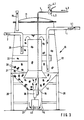
- FIG. 3 shows a first embodiment of a clarification reactor 10.
- a container can be seen which stands on a pedestal 29.
- the diameter of the container widens slightly conically from top to bottom and finally merges into a funnel-shaped base 11.
- a depression 14 is formed, which is covered at the top by means of a grate 15.
- a pipe socket 27 enables total emptying of the container 10 if necessary.
- Wall 12, floor 11 and optionally cover 13 are sufficiently insulated to be able to use the heat generated during the clarification process to increase the temperature.
- a central jet tube 20, designed as an immersion tube, is mounted by means of brackets 22, the upper end of which lies below the liquid level.
- the lower end of the jet pipe 20 is designed as a suction funnel 21, the function of which will be explained below.
- the actual ventilation unit formed from a submersible pump 40 and a water jet gas pump 30 with a Venturi tube, is located under the jet pipe 20 and in the depression 14 in the tank bottom 11.
- the gas line 4 is connected to the water jet gas pump 30.
- the submersible pump 40 pumps waste water and sludge through the water jet gas pump 30.
- the vacuum generated in this way draws in ambient air via the gas line 4 and mixes it intimately with the liquid.
- the wastewater-sludge-gas mixture then flows upwards through the jet pipe 20 in order to sink again in the outer container region, so that a circular flow occurs in the reactor 10.
- filler 28 are also filled in the form of a tubular section made of plastic, preferably rigid PVC.
- these packing elements 28 serve as an additional growth area for the microorganisms which bring about the clarification process, in particular nitrifying and denitrifying the waste water.
- air can alternately be sucked in via the line 4.1 or gas, for example compressed gas, but also exhaust gas or odor-contaminated exhaust air from production or combustion processes, via the compressed gas line 4.2, or the gas line 4 can be shut off completely.
- gas for example compressed gas, but also exhaust gas or odor-contaminated exhaust air from production or combustion processes, via the compressed gas line 4.2, or the gas line 4 can be shut off completely.
- FIGS. 4 and 5 show in longitudinal section or cross section a further reactor 10 '.
- An outer immersion tube 23 is provided between the heat-insulated container wall 12 and the inner jet pipe 20, fastened with the aid of brackets 24.
- the ventilation device consists of an immersion pump 40 which feeds four or more water jet gas pumps 30 via a line 42.
- the gas line 4 is connected via a connecting line 4.4 to the water jet gas pumps 30.
- the container area available for the fillers 28 is bounded on the outside by the outer immersion pipe 23, and on the bottom by the grate 15. Under the effect of the sewage-sludge-gas mixture, which rises upwards in the center of the inner jet pipe 20, too the Filler 28 included in the circular flow.
- reactor inlet 1.2 or sludge return pipe 3.1 are introduced tangentially into the reactor 10.
- the reactor area between the tank wall 12 and the outer immersion tube 23 is not included in the circular flow, it is not supplied with oxygen either, so that a distinctly optional environment is formed here, as is optimal for denitrification of the waste water. Because of the relatively large area, the wastewater rises slowly upwards to the reactor outlet 2, so that the sewage sludge can sediment. The outer reactor zone thus replaces its own secondary clarifier.
- the sedimented sludge can be drawn off via a sludge line 6.
- FIG. 6 shows the ventilation unit, consisting of the liquid pump 40 with motor part 41 and pump part 43.
- the sucked-in liquid-sludge mixture is fed to the water jet gas pumps 30 via distributor lines 42. These are connected to the gas line 4 via connecting lines 4.4.
- the venturi nozzle 35, in which the liquid pressure is recovered, is covered with a grille 36, which prevents packing 28 from getting into the water jet gas pumps 30.
- the average BOD exposure was 1200 mg / l.
Abstract
Description
Die Erfindung betrifft eine Kläranlage, bestehend aus einem biologischen Klärreaktor nach dem aerob/fakultativ/anaeroben Prinzip mit Füllkörpern als Aufwuchsfläche für sessile Mikroorganismen und einem Nachklärbecken, gemäß dem Oberbegriff des Anspruchs 1.The invention relates to a wastewater treatment plant, consisting of a biological wastewater treatment reactor based on the aerobic / facultative / anaerobic principle with packing elements as a growth area for sessile microorganisms and a secondary clarifier, according to the preamble of claim 1.
Ein nach dem aerob/fakultativen Prinzip arbeitender Klärreaktor ist beispielsweise bekannt aus der DE-A-37 26 949. In einem zylindrischen Behälter mit trichterförmigem Gitterboden wird durch eine Vielzahl von kugelförmigen Füllkörpern, wie sie beispielsweise in der DE-A-36 39 159 beschrieben sind, ein Reaktorbett gebildet. An der tiefsten Stelle des trichterförmigen Bodens ist eine Abzugsleitung für die Füllkörper vorgesehen. Die abgezogenen Füllkörper werden in einer externen Anlage entweder durch Wasserstrahlen oder durch Bürsten von den anhängenden Mikroorganismen gereinigt und über eine weitere Leitung dem Reaktorbett wieder zugeführt. Die üblichen Zu- und Ableitungen für Abwasser, Reinwasser und Schlamm sind ebenfalls vorgesehen.A clarifying reactor operating according to the aerobic / optional principle is known, for example, from DE-A-37 26 949. In a cylindrical container with a funnel-shaped lattice floor, a large number of spherical fillers, as described for example in DE-A-36 39 159, are used are formed, a reactor bed. At the deepest point of the funnel-shaped bottom, a discharge line for the packing is provided. The removed packing elements are cleaned in an external system either by water jets or by brushing from the attached microorganisms and fed back to the reactor bed via a further line. The usual supply and discharge lines for waste water, pure water and sludge are also provided.
Flache Klärbecken, in denen zur Erhöhung des Schlammindexes poröse Schaumstoffwürfel als Aufwuchsflächen für Mikroorganismen schwimmen, sind beispielsweise bekannt aus der EP-A-100 007, der EP-A-238 902 und der DE-A-35 23 844. Am Boden der Becken sind Druckluftbelüftungsanlagen vorgesehen, die den erforderlichen Sauerstoff eintragen. Mit Hilfe einer geeigneten Fördereinrichtung, beispielsweise einer Mammutpumpe, wird kontinuierlich ein Teil der Schaumstoffwürfel aus dem Becken abgezogen, in einer externen Anlage teilweise oder ganz von den Mikroorganismen befreit und dann dem Becken wieder zugeführt.Flat clarifiers, in which porous foam cubes float as growth areas for microorganisms to increase the sludge index, are known, for example, from EP-A-100 007, EP-A-238 902 and DE-A-35 23 844. At the bottom of the basin compressed air ventilation systems are provided that enter the required oxygen. With the aid of a suitable conveying device, for example a mammoth pump, part of the foam cubes is continuously withdrawn from the basin, partially or completely freed of the microorganisms in an external system and then returned to the basin.
Aus der DE-A-28 45 652 schließlich ist ein biologischer Klärreaktor bekannt, dessen Behälter ebenfalls ein aus Füllkörpern geschüttetes Reaktorbett sowie eine Begasungseinrichtung aufweist. Die Füllkörper besitzen Kugel- oder Torusform. Durch eine geeignete Fördereinrichtung wird kontinuierlich ein Teil der Füllkörper aus dem Reaktorbett abgezogen, in einer externen Waschanlage von den Mikroorganismen befreit und durch eine weitere Leitung in den Reaktor zurückgeführt.Finally, from DE-A-28 45 652 a biological clarification reactor is known, the container of which also has a reactor bed filled with packing and a gassing device. The packing has a spherical or toroidal shape. A suitable conveying device continuously removes a part of the packing from the reactor bed, frees the microorganisms in an external washing system and returns it to the reactor through a further line.
Den im zitierten Stand der Technik beschriebenen Maßnahmen liegt die Absicht zugrunde, einerseits den Schlammindex im Klärbecken bzw. Klärreaktor zu erhöhen, indem den Mikroorganismen zusätzliche Aufwuchsflächen in Form der Füllkörper zur Verfügung gestellt werden, andererseits aber ein Verstopfen des Reaktorbetts durch die auf den Füllkörpern wachsenden Mikroorganismen zu verhindern.The measures described in the cited prior art are based on the intention, on the one hand, of increasing the sludge index in the clarifier or clarifier by providing the microorganisms with additional growth areas in the form of the packing, but on the other hand clogging the reactor bed due to the growth on the packing To prevent microorganisms.
Das beschriebene Verfahren mit den in flachen Klärbecken schwimmenden Schaumstoffkörpern konnte sich in der Praxis nicht bewähren. Auch die übrigen Verfahren sind, soweit bekannt, nicht über das Versuchsstadium hinausgekommen.The method described with the foam bodies floating in shallow clarifiers could not prove itself in practice. As far as is known, the other processes did not go beyond the experimental stage.
Eine wesentliche Voraussetzung für eine hohe Effektivität des Klärvorgangs und eine optimale Ausnutzung der zum Betrieb einer Kläranlage aufgewendeten Energie ist eine optimale Vermischung von Abwasser, Schlamm und Luft, eine optimale Belüftung, eine optimale Temperaturführung und eine Gestaltung des Klärreaktors derart, daß die für den Abbau der verschiedenen Schadstoffe verantwortlichen Mikroorganismen die für sie optimalen Lebensbedingungen finden.An essential prerequisite for a high effectiveness of the clarification process and an optimal use of the energy used to operate a sewage treatment plant is an optimal mixing of waste water, sludge and air, an optimal ventilation, an optimal temperature control and a design of the clarification reactor in such a way that the for the dismantling of the various pollutants responsible microorganisms find the optimal living conditions for them.
Ein wesentlicher Vorgang in den aerob arbeitenden Kläranlagen ist die sogenannte Nitrifikation. Darunter versteht man die Oxidation von Ammonium zu Nitrat mit Hilfe von aeroben Bakterien. Dies sind im wesentlichen die parasymbiontisch zusammenlebenden Gattungen Nitrosomonas und Nitrobacter. Erstere sind Nitritbildner, letztere sind Nitratbildner. Als Nebenprodukt entstehen bis zu 10 % N₂O und NO. Die freiwerdende Energie in Höhe von 787 kJ/Mol wird von den Bakterien zu etwa 10 % verbraucht.An essential process in the aerobic wastewater treatment plants is the so-called nitrification. Underneath one understands the oxidation of ammonium to nitrate with the help of aerobic bacteria. These are essentially the genera living together parasymbionically Nitrosomonas and Nitrobacter. The former are nitrite formers, the latter are nitrate formers. As a by-product, up to 10% N₂O and NO are formed. The bacteria release about 78% of the energy released at 787 kJ / mol.
Werden die Nitrate zusammen mit dem gereinigten Abwasser in die Gewässer geleitet, kommt es zu der bekannten Überdüngung. Die Nitrate sollten daher in der Kläranlage abgebaut werden. Diese sogenannte Denitrifikation erfolgt ebenfalls mit Hilfe von Bakterien, z. B. Pseudomonas stutzeri oder Micrococus denitrificans. Diese Bakterien sind Anaerobier. Sie benutzen den bei der Reduktion von Nitraten freiwerdenden Sauerstoff als Wasserstoffakzeptor für den Abbau organischer Nährstoffe. Mit der dabei gewonnenen Energie halten die Bakterien ihren Stoffwechsel in Gang.If the nitrates are discharged into the water along with the cleaned wastewater, this leads to the well-known over-fertilization. The nitrates should therefore be broken down in the sewage treatment plant. This so-called denitrification is also carried out with the help of bacteria, e.g. B. Pseudomonas stutzeri or Micrococus denitrificans. These bacteria are anaerobes. They use the oxygen released during the reduction of nitrates as a hydrogen acceptor for the breakdown of organic nutrients. With the energy gained, the bacteria keep their metabolism going.
Schließlich muß das die Kläranlage verlassende Abwasser auch frei von organischen Bestandteilen, dem sogenannten Klärschlamm, sein. Klärschlamm wird üblicherweise sedimentiert. Hierzu werden große, flache, kreisförmige Becken mit einem flach-trichterförmigen Boden verwendet. Das Abwasser wird durch den Boden des Nachklärbeckens zentral zugeführt. Das Wasser-Schlamm-Gemisch steigt zunächst vom Rohrende aufwärts bis zum Flüssigkeitsspiegel, worauf die schweren Schlammbestandteile sedimentieren und sich am Beckenboden absetzen, wo sie einen entsprechenden Schlammkegel ausbilden. Enthält das Abwasser Schwimm- und Blähschlämme, sammeln sich diese an der Flüssigkeitsoberfläche an und gelangen mit dem Abwasser in die Ablaufrinne und somit in die Gewässer.Finally, the wastewater leaving the sewage treatment plant must also be free of organic constituents, the so-called sewage sludge. Sewage sludge is usually sedimented. Large, flat, circular basins with a flat, funnel-shaped bottom are used for this. The wastewater is fed centrally through the bottom of the secondary clarifier. The water-sludge mixture first rises from the end of the pipe up to the liquid level, whereupon the heavy sludge components sediment and settle on the pool floor, where they form a corresponding sludge cone. If the wastewater contains floating and bulking sludge, these accumulate on the surface of the liquid and get into the drainage channel and thus into the water with the wastewater.
Der vorliegenden Erfindung liegt die Aufgabe zugrunde, eine Kläranlage, bestehend aus einem Klärreaktor und einem Klärbecken, der eingangs genannten Art anzugeben, die einfach und preiswert herzustellen ist, eine einfache, robuste, energiesparende Betriebsweise ermöglicht und den am Klärvorgang beteiligten Bakterien und Mikroorganismen optimale Lebensbedingungen bietet.The present invention has for its object a Wastewater treatment plant, consisting of a wastewater treatment reactor and a settling tank, of the type mentioned at the outset, which is simple and inexpensive to manufacture, enables simple, robust, energy-saving operation and offers the living conditions optimal for the bacteria and microorganisms involved in the treatment process.
Diese Aufgabe wird gelöst durch eine gattungsgemäße Kläranlage mit den Merkmalen gemäß Kennzeichen des Anspruchs 1.This object is achieved by a generic sewage treatment plant with the features according to the characterizing part of claim 1.
Damit bilden sich in der Kläranlage im wesentlichen vier Verfahrenszonen aus:
- 1. Eine intensiv belüftete primäre Zone im Zentrum des Reaktorbehälters. Hier werden Abwasser, Biomasse und Luft innig vermischt. Hier wird das Abwasser nitrifiziert.
- 2. Eine weniger belüftete sekundäre Zone in dem das innere als Tauchrohr ausgebildete Strahlrohr umgebenden Behälterbereich. Hier wird das Abwasser ebenfalls nitrifiziert.
- 3. Eine leicht bis mäßig fakultative, anoxische dritte Zone. Diese dritte Zone liegt im wesentlichen unterhalb der zweiten Zone und umfaßt auch den trichterförmigen Bodenbereich. In dieser Zone wird das Abwasser denitrifiziert.
- 4. Eine stark fakultative, vierte Zone im Nachklärbecken. Hier wird das Abwasser vollständig denitrifiziert. Der Klärschlamm wird sedimentiert.
- 1. An intensely ventilated primary zone in the center of the reactor vessel. Here wastewater, biomass and air are mixed intimately. Here the wastewater is nitrified.
- 2. A less ventilated secondary zone in the container area surrounding the inner jet tube which is designed as a dip tube. The wastewater is also nitrified here.
- 3. A mild to moderate optional, anoxic third zone. This third zone lies essentially below the second zone and also includes the funnel-shaped base area. The wastewater is denitrified in this zone.
- 4. A strongly optional fourth zone in the secondary clarifier. Here the wastewater is completely denitrified. The sewage sludge is sedimented.
Auf analoge Weise werden auch Phosphor- und Schwefelverbindungen mit Hilfe spezifischer Bakterien abgebaut.In an analogous way, phosphorus and sulfur compounds are made using specific bacteria reduced.
Dank der Kreisströmung durch die erste, zweite und dritte Zone werden Abwasser und Schlamm mehrmals dem aeroben Teil des Reaktors zugeführt, wo optimale Bedingungen für die Nitrifikation vorliegen, ebenso oft aber auch dem fakultativen Teil des Reaktors, wo optimale Bedingungen für die Denitrifikation vorliegen. Insbesondere im trichterförmigen Bodenbereich bildet sich ein ausgeprägt fakultatives Milieu für die erforderliche Denitrifikation aus.Thanks to the circular flow through the first, second and third zones, wastewater and sludge are fed several times to the aerobic part of the reactor, where optimal conditions for nitrification are present, but also often to the optional part of the reactor, where optimal conditions for denitrification are present. Particularly in the funnel-shaped bottom area, a distinctly optional environment for the necessary denitrification develops.
Von besonderer Bedeutung für die vorliegende Erfindung ist der Schutz des Reaktors gegen Wärmeverluste einerseits und das angegebene Verhältnis von Reaktorhöhe zu Reaktordurchmesser bzw. -breite andererseits. Beide Maßnahmen sorgen dafür, daß die beim Bakterienstoffwechsel entstehende Wärmeenergie im Reaktor verbleibt. Auf diese Weise wird es möglich, die in wissenschaftlichen Untersuchungen bestätigte Tatsache auszunutzen, daß der Bakterienstoffwechsel und damit der Klärvorgang schneller ablaufen, wenn die Temperatur höher liegt, als es in herkömmlichen Kläranlagen der Fall ist, wo die Becken direkt in das Erdreich eingebettet sind und somit dessen Temperatur annehmen oder die Behälter frei stehen und somit die Lufttemperatur annehmen.Of particular importance for the present invention is the protection of the reactor against heat losses on the one hand and the specified ratio of reactor height to reactor diameter or width on the other hand. Both measures ensure that the thermal energy generated during bacterial metabolism remains in the reactor. In this way, it becomes possible to take advantage of the fact confirmed in scientific studies that the bacterial metabolism and thus the clarification process take place more quickly when the temperature is higher than is the case in conventional sewage treatment plants, where the basins are embedded directly in the soil and thus assume its temperature or the containers are free and thus assume the air temperature.
Von hervorragender Bedeutung für die Erfindung ist weiterhin die Verwendung einer Wasserstrahlgaspumpe mit Venturirohr, deren Wasserstrahl von einer Flüssigkeitspumpe, vorzugsweise einer auf dem Reaktorboden stehenden Tauchpumpe, erzeugt wird. Dadurch kann in vielen Fällen der in den bekannten druckbelüfteten Kläranlagen erforderliche gesonderte Drucklufterzeuger entfallen. Darüber hinaus stellt sich eine äußerst intensive Vermischung des angesaugten Gases mit dem Abwasserstrahl ein. Durch das nachgeschaltete Venturirohr wird der in der Düse entstehende Druckabfall mit Ausnahme des geringen Reibungsanteils und des zur Luftansaugung erforderlichen Energieanteils wiedergewonnen. Der zum Betrieb einer solchen Injektor-Belüftung erforderliche Energiebedarf ist erheblich geringer als der Energiebedarf herkömmlicher, separater Druckluftgebläse. Gleichzeitig sorgt der Wasserstrahl für die erforderliche Umwälzung der zu klärenden Flüssigkeit, wodurch die Mikroorganismen optimal mit Sauerstoff und Nährstoffen versorgt werden. Schließlich wird dadurch auch einer Entstehung von unkontrollierten Faulzonen vorgebeugt.Of outstanding importance for the invention is furthermore the use of a water jet gas pump with a Venturi tube, the water jet of which is generated by a liquid pump, preferably a submersible pump standing on the reactor floor. In many cases, this means that the separate compressed air generator required in the known pressure-ventilated sewage treatment plants can be dispensed with. In addition, there is an extremely intensive mixing of the sucked gas with the Waste water jet on. The pressure drop in the nozzle is recovered by the downstream Venturi tube, with the exception of the low friction component and the energy component required for air intake. The energy required to operate such an injector ventilation is considerably lower than the energy required by conventional, separate compressed air blowers. At the same time, the water jet ensures the necessary circulation of the liquid to be clarified, which optimally supplies the microorganisms with oxygen and nutrients. Ultimately, this also prevents the development of uncontrolled foul zones.
Von entscheidender Bedeutung für die vorliegende Erfindung ist schließlich, daß die von der Belüftungseinrichtung ausgebildete Kreisströmung kontinuierlich einen Teil der Füllkörper erfaßt. Das heißt, daß ein Teil der Füllkörper am Boden des inneren Strahlrohrs angesaugt und durch die erste Zone nach oben gewirbelt wird, um dann allmählich durch die zweite und dritte Zone hindurch wieder bis zur Ansaugstelle zu gelangen. Die Füllkörper bilden also im Gegensatz zu den bekannten Lösungen kein definiertes Reaktorbett, das verblocken und verstopfen könnte. Wie mehrmonatige Versuche gezeigt haben, sind die Füllkörper frei von den in den bekannten Festbettreaktoren zu beobachtenden mehrere Zentimeter langen Bakterienfäden. Gleichwohl steigt die Raumbelastung BR auf bis zu 3 kg BSB/m³ · d an, ohne daß die Nitrifikation zum Stehen gekommen wäre. Dies ist besonders überraschend, da laut der einschlägigen Literatur die Nitrifikation nur bei Raumbelastungen BR = 0,2 - 0,4 kg BSB/m³ · d ablaufen soll.Finally, it is of crucial importance for the present invention that the circular flow formed by the ventilation device continuously captures a part of the packing. This means that a part of the packing is sucked in at the bottom of the inner jet pipe and swirled upward through the first zone, in order to then gradually get back through the second and third zone to the suction point. In contrast to the known solutions, the packing elements do not form a defined reactor bed that could block and clog. As experiments lasting several months have shown, the packing is free from the several centimeter long bacterial threads that can be observed in the known fixed bed reactors. Nevertheless, the space load B R increases up to 3 kg BOD / m³ · d without the nitrification having come to a standstill. This is particularly surprising since, according to the relevant literature, nitrification should only take place at room loads B R = 0.2 - 0.4 kg BOD / m³ · d.
Gemäß einer Weiterbildung der Erfindung ist der Klärreaktor mittels Deckel vorzugsweise gasdicht verschlossen. Hierdurch wird zunächst das unerwünschte Entweichen von Wärmeenergie verhindert. Dank des gasdichten Verschlusses lassen sich jedoch zusätzliche Effekte erreichen. Stickoxide und Geruchsstoffe können nicht unkontrolliert in die Atmosphäre gelangen. Wichtiger ist jedoch, daß der Reaktor mit speziellen Gasen, beispielsweise mit reinem Sauerstoff begast und der unverbrauchte Gasanteil wiedergewonnen werden kann.According to a development of the invention, the clarification reactor is preferably sealed gas-tight by means of a cover. In this way, the undesirable escape of thermal energy prevented. Thanks to the gas-tight closure, however, additional effects can be achieved. Nitrogen oxides and odorous substances cannot escape into the atmosphere in an uncontrolled manner. It is more important, however, that the reactor be gassed with special gases, for example pure oxygen, and that the unused gas portion can be recovered.
Dank der besonderen Konstruktion eignet sich der erfindungsgemäße Reaktor auch als Bio-Filter zur Reinigung von Abgasen bzw. Abluft. Bei vielen Prozessen entstehen stark riechende, teilweise auch gesundheitsschädliche (Merkaptane) Abgase, z. B. in Form von Brüden bei der thermischen Trocknung oder Verbrennung von Klärschlamm. Diese Abgase können über die Gasleitung in den Reaktor eingeführt werden, wo sie dank der großen Biomasse, des großen Flüssigkeitsvolumens und der gasdichten Konstruktion zusammen mit dem Abwasser durch die Mikroorganismen gereinigt werden.Thanks to the special construction, the reactor according to the invention is also suitable as a bio-filter for cleaning exhaust gases or exhaust air. In many processes, strongly smelling, sometimes also harmful (mercaptans) exhaust gases, e.g. B. in the form of vapors in the thermal drying or combustion of sewage sludge. These exhaust gases can be introduced into the reactor via the gas line, where, thanks to the large biomass, the large liquid volume and the gastight construction, they are cleaned together with the waste water by the microorganisms.
Schließlich kann im Reaktor je nach Bedarf Überdruck oder Unterdruck erzeugt werden, wobei sich überraschenderweise herausgestellt hat, daß dem Unterdruck die weitaus größere Bedeutung zukommt.Finally, overpressure or underpressure can be generated in the reactor as required, and it has surprisingly turned out that the underpressure is of far greater importance.
Unterdruck entsteht bereits in der Wasserstrahlgaspumpe. Er sorgt dafür, daß Gas bzw. Luft angesaugt und innigst mit dem Abwasser vermischt wird. Der Unterdruck sorgt ferner dafür, daß in der Flüssigkeit gelöste Gase verstärkt ausperlen. Da Sauerstoff und Stickstoff mit der Belüftungseinrichtung ständig nachgeliefert werden, werden mit Hilfe des Unterdrucks in erster Linie die beim Klärvorgang entstehenden Schadgase aus der Flüssigkeit entfernt.Vacuum is already created in the water jet gas pump. It ensures that gas or air is sucked in and intimately mixed with the waste water. The negative pressure also ensures that gases dissolved in the liquid bubble out more. Since oxygen and nitrogen are continuously supplied with the aeration device, the negative gases are primarily removed from the liquid with the help of the vacuum.
Schließlich verbessert ein Unterdruck im Reaktorbehälter auch den Gaseintrag mit Hilfe der Wasserstrahlgaspumpe. Insbesondere bei tiefen Reaktorbehältern erzeugt die Flüssigkeitssäule über der Belüftungseinrichtung einen erheblichen Gegendruck. Dieser kann durch einen entsprechenden Unterdruck wirksam herabgesetzt werden.Finally, a vacuum in the reactor vessel improves also the gas entry with the help of the water jet gas pump. In the case of deep reactor vessels in particular, the liquid column above the aeration device generates a considerable back pressure. This can be effectively reduced by a corresponding negative pressure.
Es versteht sich, daß der Gegendruck der Flüssigkeitssäule über der Belüftungseinrichtung ganz oder teilweise auch dadurch beseitigt werden kann, daß die Gaszufuhr zur Wasserstrahlgaspumpe mit Hilfe einer Druckgasleitung erfolgt.It goes without saying that the back pressure of the liquid column above the ventilation device can also be completely or partially eliminated by supplying the gas to the water jet gas pump with the aid of a compressed gas line.
Dabei kann in der Gasleitung zur Belüftungseinrichtung zusätzlich ein Umschalt- bzw. Abschaltventil vorgesehen sein, so daß je nach Bedarf mit Überdruck, Atmosphärendruck oder auch ohne Gaszufuhr gearbeitet werden kann.In this case, a switchover or shutoff valve can additionally be provided in the gas line to the ventilation device, so that, depending on requirements, it is possible to work with excess pressure, atmospheric pressure or even without gas supply.
Eine wesentliche Steigerung der Denitrifikation wird durch intermittierenden Betrieb des Reaktors erreicht. Dazu wird zeitweise die Gas- bzw. Luftzufuhr abgesperrt, während die Umwälzpumpe weiterläuft. Aufgrund der hohen Raumbelastung und der großen Menge atmungsaktiver Biomasse kommt es schnell zu einem Sauerstoffdefizit und somit zu den gewünschten fakultativen bzw. anoxischen Bedingungen. Dank der Umwälzpumpe bleiben Schlamm, nitrathaltiges Abwasser und Mikroorganismen innig vermischt. Hilfseinrichtungen wie in herkömmlichen Kläranlagen entfallen.A significant increase in denitrification is achieved by intermittent operation of the reactor. For this purpose, the gas or air supply is temporarily shut off while the circulation pump continues to run. Due to the high space load and the large amount of breathable biomass, there is an oxygen deficiency and thus the desired optional or anoxic conditions. Thanks to the circulation pump, sludge, nitrate-containing wastewater and microorganisms remain intimately mixed. Auxiliary devices as in conventional sewage treatment plants are eliminated.
Gemäß einer vorteilhaften Weiterbildung der Erfindung ist der den Füllkörpern zur Verfügung stehende Reaktorbereich durch einen für Flüssigkeit und Schlamm durchlässigen, vorzugsweise trichterförmigen Rost nach unten begrenzt. Hierdurch wird sichergestellt, daß die Füllkörper immer in die Ansaugzone gelangen, Schlamm und Abwasser dagegen auch in die oben erwähnte dritte Zone mit fakultativem, d. h. anoxischem Milieu.According to an advantageous development of the invention, the reactor area available to the packing elements is limited at the bottom by a preferably funnel-shaped grate that is permeable to liquid and sludge. This ensures that the packing always gets into the suction zone, whereas sludge and waste water also go into the above-mentioned third zone with an optional, ie anoxic milieu.
Um die Umwälzung der Füllkörper zu verbessern, empfiehlt es sich, das untere Ende des inneren Strahlrohrs als Ansaugtrichter auszubilden.In order to improve the circulation of the packing, it is advisable to design the lower end of the inner jet pipe as a suction funnel.
Um bei Wartung oder Reparatur die Belüftungseinrichtung und insbesondere die auf dem Boden des Behälters vorzugsweise in einer Vertiefung stehende Tauchpumpe ohne größere Demontagen nach oben herausziehen zu können, ist im Rost ein zentrales Schutzrohr vorgesehen, dessen Durchmesser dem Durchmesser der Belüftungseinrichtung, vorzugsweise der Pumpe, entspricht.In order to be able to pull out the ventilation device and in particular the submersible pump, which is preferably in a recess on the bottom of the container, for maintenance or repair without major disassembly, a central protective tube is provided in the grate, the diameter of which corresponds to the diameter of the ventilation device, preferably the pump .
Gemäß einer Weiterbildung der Erfindung kann zwischen Reaktorwand und innerem Strahlrohr ein zweites Tauchrohr eingesetzt werden, wobei dieses für eine optimale Rückgewinnung der Wärmeenergie aus der wandnahen Flüssigkeit ausgelegt ist. Das Durchmesserverhältnis von innerem Strahlrohr zu äußerem Tauchrohr sollte zwischen 1 : 5 und 3 : 4 liegen. In der so gebildeten äußeren Ringzone steigt die bereits gereinigte Flüssigkeit langsam nach oben zum Überlauf. Da dieser Zone kein Sauerstoff mehr zugeführt wird, bildet sich dort ein ausgeprägt fakultatives Milieu aus. Das Abwasser wird denitrifiziert. Gleichzeitig haben die sedimentationsfähigen Schlämme ausreichend Zeit, sich abzusetzen. Der äußere Behälterbereich wirkt als Nachklärzone und erspart unter Umständen den Bau eines gesonderten Nachklärbeckens.According to a development of the invention, a second immersion tube can be used between the reactor wall and the inner jet pipe, this being designed for optimal recovery of the thermal energy from the liquid near the wall. The diameter ratio of the inner jet pipe to the outer dip pipe should be between 1: 5 and 3: 4. In the outer ring zone thus formed, the already cleaned liquid slowly rises to the overflow. Since oxygen is no longer supplied to this zone, a distinctly optional environment is formed there. The wastewater is denitrified. At the same time, the sedimentable sludges have enough time to settle. The outer tank area acts as a secondary clarification zone and may save the construction of a separate secondary clarification tank.
Vorteilhafterweise können Reaktorzulaufrohr bzw. Schlammrückführungsrohr tangential in den Klärreaktor eingeführt sein. Auf diese Weise wird der Kreisströmung im Reaktor eine Drallströmung überlagert, was die Durchmischung noch weiter verbessert.The reactor feed pipe or sludge return pipe can advantageously be introduced tangentially into the clarification reactor. In this way, a swirl flow is superimposed on the circular flow in the reactor, which further improves the mixing.
Gemäß einer Ausgestaltung der Erfindung erweitert sich der den Füllkörpern zur Verfügung stehende Reaktorbereich nach unten konisch. Hierdurch wird einer möglichen Anlagerung der Füllkörper an der Wand, ausgelöst durch Kreisströmung und gegebenenfalls Drallströmung, sicher vorgebeugt.According to one embodiment of the invention, the reactor area available to the packing is tapered downwards. This reliably prevents possible accumulation of the packing elements on the wall, triggered by circular flow and, if necessary, swirl flow.
Vorzugsweise bestehen die Füllkörper aus extrudierten Kunststoff-Rohrabschnitten, vorzugsweise aus Hart-PVC. Dieses Material ist leicht, preiswert und hat sich in den Versuchen optimal bewährt.The fillers preferably consist of extruded plastic pipe sections, preferably of rigid PVC. This material is light, inexpensive and has proven itself optimally in the tests.
Wie schon erwähnt, ist auch eine gute Nachklärung der gereinigten Abwässer erforderlich. Für den Fall, daß ein eigenes Nachklärbecken vorgesehen ist, empfiehlt es sich, dieses wie an sich bekannt mit einem flach-trichterförmigen Boden und einem zentralen Zulauf auszuführen, den zentralen Zulauf jedoch bis knapp unter den Flüssigkeitsspiegel hochzuziehen und ferner das Becken in zwei vorzugsweise konzentrische Teilbecken zu unterteilen, indem eine Tauchwand eingebaut wird. Hierdurch wird erreicht, daß ausgehend vom zentralen Zulauf eine nur abwärts gerichtete Flüssigkeitsströmung gebildet wird, die die Sedimentation wirksam unterstützt, und daß die Sedimentation hauptsächlich im ersten, inneren Teilbecken erfolgt.As already mentioned, a good clarification of the cleaned waste water is also necessary. In the event that a separate clarifier is provided, it is advisable to do this as is known per se with a flat funnel-shaped bottom and a central inlet, but pulling the central inlet up to just below the liquid level and furthermore the tank into two, preferably concentric Subdivide partial pools by installing a baffle. This ensures that, starting from the central inlet, an only downward liquid flow is formed, which effectively supports the sedimentation, and that the sedimentation takes place mainly in the first, inner partial basin.
Bläh- und Schwimmschlammanteile im nachzuklärenden Abwasser werden durch die Tauchwand zurückgehalten. In diesem Fall empfiehlt es sich, im inneren Teilbecken eine Abzugsrinne für Schwimmschlamm vorzusehen.Bulking and floating sludge in the wastewater to be clarified are retained by the baffle. In this case, it is advisable to provide a drainage channel for sludge in the inner part of the pool.
Anhand der Zeichnung soll die Erfindung in Form von Ausführungsbeispielen näher erläutert werden. Es zeigen
- Fig. 1 eine schematische Darstellung einer Kläranlage, bestehend aus einem Klärreaktor und einem gesonderten Nachklärbecken,
- Fig. 2 einen Schnitt durch ein gesondertes Nachklärbecken,
- Fig. 3 einen Vertikalschnitt durch einen ersten Klärreaktor,
- Fig. 4 einen Vertikalschnitt durch einen zweiten Klärreaktor,
- Fig. 5 einen Horizontalschnitt durch den Klärreaktor der Fig. 4 und
- Fig. 6 eine Umwälz- und Belüftungseinheit.
- 1 is a schematic representation of a sewage treatment plant, consisting of a clarification reactor and a separate clarifier,
- 2 shows a section through a separate clarifier,
- 3 shows a vertical section through a first clarification reactor,
- 4 shows a vertical section through a second clarification reactor,
- Fig. 5 is a horizontal section through the clarification reactor of Fig. 4 and
- Fig. 6 is a circulation and ventilation unit.
Fig. 1 zeigt schematisch eine Kläranlage, bestehend aus einem auf Füßen 29 aufgestellten Klärreaktor 10 und einem gesonderten Nachklärbecken 50. Der Behälter des Klärreaktors 10 ist mit einem Deckel 13 vorzugsweise gasdicht verschlossen. Das zu klärende Abwasser wird über eine Reaktorzuleitung 1 zugeführt, das gereinigte Abwasser über eine Reaktorableitung 2 ab- und dem Nachklärbecken 50 zugeführt. Über eine Gasleitung 4 wird der Flüssigkeit im Inneren des Reaktors 10 der erforderliche Sauerstoff zugeführt.1 schematically shows a sewage treatment plant, consisting of a
Das Nachklärbecken 50, das in Fig. 2 im Schnitt und vergrößert abgebildet ist, ist kreisrund und besitzt einen flach-trichterförmigen Boden 51. Im Zentrum ist ein Auflager 57 für eine Schlammräumbrücke 58 angeordnet.The
Durch den Einbau einer Tauchwand 52 ist das Nachklärbecken 50 in zwei konzentrische Teilbecken 53, 54 unterteilt. Die Austrittsöffnung 2.1 der Leitung 2 endet knapp unter dem Flüssigkeitsspiegel. Da die Flüssigkeit auf ihrem Weg zu der am Umfang des Nachklärbeckens 50 vorgesehenen Abzugsrinne 55 unter der Tauchwand 52 hindurch muß, entsteht im inneren Teilbecken 53 eine ausgeprägte, nach unten gerichtete Strömungskomponente, die die Sedimentation der Klärschlämme wirksam unterstützt. Die Hauptmenge der sedimentierten Klärschlämme sammelt sich im Bereich des inneren Teilbeckens 53, wo sie wie an sich bekannt mit Hilfe der Schlammräumbrücke 58 entfernt wird.By installing a
Falls auch Schwimm- und Blähschlämme in das Nachklärbecken 50 gelangen, werden diese von der Tauchwand 52 zurückgehalten. Sie können mit einer gesonderten Abzugsrinne 56 aufgefangen und mit Hilfe einer Schlammrückführungsleitung 3 dem Klärreaktor wieder zugeführt werden.If floating and expanding sludge also get into the
Das gereinigte und nachgeklärte Abwasser wird von der Abzugsrinne 55 über eine Leitung 5 in den natürlichen Wasserkreislauf abgeleitet.The cleaned and clarified wastewater is discharged from the
Fig. 3 zeigt eine erste Ausführungsform eines Klärreaktors 10. Man erkennt einen Behälter, der auf einem Fußgestell 29 steht. Der Durchmesser des Behälters erweitert sich von oben nach unten leicht konisch und geht schließlich in einen trichterförmigen Boden 11 über. Im Zentrum des Bodens 11 ist eine Vertiefung 14 ausgebildet, die oben mit Hilfe eines Rostes 15 abgedeckt ist. Ein Rohrstutzen 27 ermöglicht im Bedarfsfall die totale Entleerung des Behälters 10.FIG. 3 shows a first embodiment of a
Wand 12, Boden 11 und gegebenenfalls Deckel 13 sind ausreichend wärmegedämmt, um die beim Klärvorgang entstehende Wärme zu einer Temperaturerhöhung ausnützen zu können.
Im Inneren des Behälters 10 ist mittels Halterungen 22 ein zentrales, als Tauchrohr ausgebildetes Strahlrohr 20 montiert, dessen oberes Ende unterhalb des Flüssigkeitsspiegels liegt. Das untere Ende des Strahlrohrs 20 ist als Ansaugtrichter 21 ausgebildet, dessen Funktion noch erläutert werden soll. Unter dem Strahlrohr 20 und in der Vertiefung 14 im Behälterboden 11 steht die eigentliche Belüftungseinheit, gebildet aus einer Tauchpumpe 40 und einer Wasserstrahlgaspumpe 30 mit Venturirohr. An die Wasserstrahlgaspumpe 30 ist die Gasleitung 4 angeschlossen. Die Tauchpumpe 40 pumpt Abwasser und Schlamm durch die Wasserstrahlgaspumpe 30. Der dabei erzeugte Unterdruck saugt Umgebungsluft über die Gasleitung 4 an und vermischt sie innig mit der Flüssigkeit. Das Abwasser-Schlamm-Gas-Gemisch strömt dann durch das Strahlrohr 20 nach oben, um im äußeren Behälterbereich wieder abzusinken, so daß im Reaktor 10 eine Kreisströmung entsteht.In the interior of the
Im Reaktor 10 sind ferner Füllkörper 28 in Form von Rohrabschnitt aus Kunststoff, vorzugsweise Hart-PVC eingefüllt. Diese Füllkörper 28 dienen wie an sich bekannt als zusätzliche Aufwuchsfläche für die Mikroorganismen, die den Klärvorgang bewirken, insbesondere das Abwasser nitrifizieren und denitrifizieren.In the
Sobald ein Füllkörper 28 in den Sogbereich des im Strahlrohr 20 nach oben steigenden Abwasser-Schlamm-Gas-Gemischs gelangt, wird er mit diesem nach oben gefördert. Auf diese Weise unterliegen auch die Füllkörper 28 einem ständigen Kreislauf im Reaktor 10. Dies ermöglicht eine optimale Versorgung der Mikroorganismen mit Nährstoffen und Sauerstoff; gleichzeitig wird verhindert, daß Füllkörper 28 und Mikroorganismen zu einem unbeweglichen Block zusammenwachsen können, wie es in herkömmlichen Festbettreaktoren immer wieder beobachtet wird.As soon as a
Überraschenderweise konnte festgestellt werden, daß die in den bekannten Anlagen immer zu beobachtenden, zentimeterlangen Bakterienfäden nicht auftreten.Surprisingly, it was found that the centimeter-long bacterial threads which are always observed in the known plants do not occur.
In den weitaus überwiegenden Fällen wird es genügen, wenn über die Gasleitung 4 Luft angesaugt wird. In speziellen Fällen muß jedoch mit besonderen Gasen, beispielsweise reinem Sauerstoff, gearbeitet werden. Hier zeigt sich der Vorteil des gasdichten Deckels 13, da er es ermöglicht, daß nicht verbrauchte Gasanteile gesammelt und über die Ableitung 16 wiederverwendet werden können.In the vast majority of cases, it will suffice if 4 air is sucked in via the gas line. In special cases, however, special gases, for example pure oxygen, must be used. This shows the advantage of the gas-
Dank eines in die Gasleitung 4 eingesetzten Um- und Abschaltventils 4.3 kann abwechselnd Luft über die Leitung 4.1 oder Gas, beispielsweise Druckgas, aber auch Abgas oder geruchsbelastete Abluft aus Produktions- oder Verbrennungsprozessen, über die Druckgasleitung 4.2 angesaugt oder die Gasleitung 4 völlig abgesperrt werden.Thanks to a changeover and shutoff valve 4.3 inserted in the
Die Fig. 4 und 5 zeigen im Längsschnitt bzw. Querschnitt einen weiteren Reaktor 10′. Zwischen der wärmegedämmten Behälterwand 12 und dem inneren Strahlrohr 20 ist ein äußeres Tauchrohr 23 vorgesehen, befestigt mit Hilfe von Halterungen 24. Die Belüftungseinrichtung besteht aus einer Tauchpumpe 40, die über eine Leitung 42 vier oder mehr Wasserstrahlgaspumpen 30 speist. Die Gasleitung 4 ist über je eine Verbindungsleitung 4.4 an die Wasserstrahlgaspumpen 30 angeschlossen.4 and 5 show in longitudinal section or cross section a further reactor 10 '. An
Der den Füllkörpern 28 zur Verfügung stehende Behälterbereich ist nach außen begrenzt durch das äußere Tauchrohr 23, nach unten durch den Rost 15. Unter der Wirkung des Abwasser-Schlamm-Gas-Gemischs, das im Zentrum des inneren Strahlrohrs 20 nach oben steigt, werden auch die Füllkörper 28 in die Kreisströmung einbezogen.The container area available for the
Um der Kreisströmung eine Drallströmung überlagern zu können, sind Reaktorzulauf 1.2 bzw. Schlammrückführungsrohr 3.1 tangential in den Reaktor 10 eingeführt.In order to be able to superimpose a swirl flow on the circular flow, reactor inlet 1.2 or sludge return pipe 3.1 are introduced tangentially into the
Da der Reaktorbereich zwischen der Behälterwand 12 und dem äußeren Tauchrohr 23 nicht in die Kreisströmung einbezogen ist, wird er auch nicht mit Sauerstoff versorgt, so daß sich hier ein ausgeprägt fakultatives Milieu ausbildet, wie es für eine Denitrifizierung des Abwassers optimal ist. Aufgrund der relativ großen Fläche steigt das Abwasser nur langsam nach oben zum Reaktorablauf 2, so daß die Klärschlämme sedimentieren können. Die äußere Reaktorzone ersetzt somit ein eigenes Nachklärbecken.Since the reactor area between the
Der sedimentierte Schlamm kann über eine Schlammleitung 6 abgezogen werden.The sedimented sludge can be drawn off via a sludge line 6.
Fig. 6 zeigt die Belüftungseinheit, bestehend aus der Flüssigkeitspumpe 40 mit Motorteil 41 und Pumpenteil 43. Das angesaugte Flüssigkeits-Schlamm-Gemisch wird über Verteilerleitungen 42 den Wasserstrahlgaspumpen 30 zugeführt. Diese sind über Verbindungsleitungen 4.4 mit der Gasleitung 4 verbunden. Die Venturi-Düse 35, in der der Flüssigkeitsdruck wiedergewonnen wird, ist mit einem Gitter 36 abgedeckt, welches verhindert, daß Füllkörper 28 in die Wasserstrahlgaspumpen 30 gelangen können.6 shows the ventilation unit, consisting of the
Mit einem Reaktor, wie er in Fig. 3 dargestellt ist, wurden mehrmonatige Versuche durchgeführt. Dabei wurden beispielsweise im Januar 1990 mit einem spezifischen Abwasser folgende Werte gemessen:
Reaktorvolumen = 0,50 m³
Füllkörpervolumen = 0,19 m³
Flüssigkeitstemperatur = 25 Grad C
Außentemperatur = 0 Grad C
Abwassermenge Q = 900 l/d
BSB im Zulauf = 1,2 g/l
Raumbelastung BR ≧ 2,0 kg BSB/m³ · d
Im Mittel wurden folgende Werte gemessen:
Im Zulauf:
Ammonium-Stickstoff (NH₄-N) = 41,33 mg/l
Nitrat-Stickstoff (NO₃-N) = 3,54 mg/l
Gesamt-Stickstoff = 44,87 mg/l
Im Ablauf:
Ammonium-Stickstoff (NH₄-N) = 2,09 mg/l
Nitrat-Stickstoff (NO₃-N) = 1,83 mg/l
Gesamt-Stickstoff = 3,92 mg/l
entspricht einem Abbau von 91,27 %.Experiments lasting several months were carried out with a reactor as shown in FIG. 3. In January 1990, for example, the following values were measured with a specific wastewater:
Reactor volume = 0.50 m³
Packing volume = 0.19 m³
Liquid temperature = 25 degrees C.
Outside temperature = 0 degrees C.
Waste water quantity Q = 900 l / d
BOD in the feed = 1.2 g / l
Space load BR ≧ 2.0 kg BOD / m³ · d
The following values were measured on average:
Incoming:
Ammonium nitrogen (NH₄-N) = 41.33 mg / l
Nitrate nitrogen (NO₃-N) = 3.54 mg / l
Total nitrogen = 44.87 mg / l
In the process:
Ammonium nitrogen (NH₄-N) = 2.09 mg / l
Nitrate nitrogen (NO₃-N) = 1.83 mg / l
Total nitrogen = 3.92 mg / l
corresponds to a degradation of 91.27%.
Die durchschnittliche BSB-Belastung betrug 1200 mg/l.The average BOD exposure was 1200 mg / l.
Um 100 kg BSB umzusetzen, sind 5 kg N erforderlich. Bei 1200 mg/l BSB entspricht dies etwa 60 mg/l N. Die Stickstoffbilanz weist einen Stickstoff-Fehlbedarf von 15 mg/l aus, bezogen auf den Stickstoff im Zulauf. Da andere Stickstoffquellen nicht gegeben waren, es wurde kein Harnstoff oder dergleichen zudosiert, kann der Fehlbedarf nur aus dem Luftstickstoff gedeckt worden sein.To implement 100 kg BOD, 5 kg N are required. At 1200 mg / l BOD this corresponds to about 60 mg / l N. The nitrogen balance shows a nitrogen deficit of 15 mg / l, based on the nitrogen in the feed. Since there were no other nitrogen sources, no urea or the like was metered in, the deficiency can only have been covered by atmospheric nitrogen.
Es ist unter Verwendung eines erfindungsgemäßen Klärreaktors überraschenderweise möglich, auch ausgesprochen stickstoffarme Abwässer, wie sie beispielsweise im Weinbau, in Kellereien und in Brauereien anfallen, zu klären, ohne daß wie bei herkömmlichen Kläranlagen nötig Stickstoff in Form von Harnstoff zudosiert werden muß.It is surprisingly possible, using a clarification reactor according to the invention, to also clarify extremely nitrogen-poor wastewater, such as is obtained, for example, in viticulture, in wineries and in breweries, without nitrogen having to be metered in as urea, as is the case with conventional sewage treatment plants.
Es versteht sich, daß auch die im Abwasser enthaltenen Phosphor-Verbindungen entsprechend abgebaut wurden.It goes without saying that the phosphorus compounds contained in the waste water have also been broken down accordingly.
Claims (15)
Applications Claiming Priority (4)
| Application Number | Priority Date | Filing Date | Title |
|---|---|---|---|
| DE3916520 | 1989-05-20 | ||
| DE19893916520 DE3916520A1 (en) | 1989-05-20 | 1989-05-20 | Biological clarifier vessel using aerobic-selective principle - comprises insulated vertical cylindrical vessel divided into concentric zones for aeration, clarification and sedimentation |
| DE19898906830 DE8906830U1 (en) | 1989-05-20 | 1989-06-03 | |
| DE8906830U | 1989-06-03 |
Publications (1)
| Publication Number | Publication Date |
|---|---|
| EP0399380A1 true EP0399380A1 (en) | 1990-11-28 |
Family
ID=25881106
Family Applications (1)
| Application Number | Title | Priority Date | Filing Date |
|---|---|---|---|
| EP19900109389 Withdrawn EP0399380A1 (en) | 1989-05-20 | 1990-05-18 | Waste water treatment plant |
Country Status (2)
| Country | Link |
|---|---|
| EP (1) | EP0399380A1 (en) |
| DE (2) | DE8906830U1 (en) |
Cited By (15)
| Publication number | Priority date | Publication date | Assignee | Title |
|---|---|---|---|---|
| WO1993025485A1 (en) * | 1992-06-10 | 1993-12-23 | Paques B.V. | System and process for purifying waste water which contains nitrogenous compounds |
| EP0643018A2 (en) * | 1993-09-15 | 1995-03-15 | Erich Helmut Dipl.-Ing. Zimmer | Process and apparatus for clarifying waste waters according to the aerobic/facultative principle |
| NL9301791A (en) * | 1993-10-15 | 1995-05-01 | Biothane Systems Int Bv | Method of purifying waste water |
| WO1995023767A1 (en) * | 1994-03-03 | 1995-09-08 | Nordic Water Products Ab | Processing water in a biologically activated and continuously operating granular filter bed |
| WO1996011168A1 (en) * | 1994-10-10 | 1996-04-18 | Patent Care B.V. | Biological waste fluid cleaner |
| WO1997043220A1 (en) * | 1996-05-14 | 1997-11-20 | Luehr Wolfgang | Clarification plant for water purification |
| GB2315264A (en) * | 1995-10-27 | 1998-01-28 | Sam Kwang Aqua Clear Inc | Waste treatment apparatus |
| DE10035903A1 (en) * | 2000-07-21 | 2002-02-07 | Volker Lenski | Bioreactor for small scale water purification comprises outer tube with base, inlet and outlet, concentric inner tube, aeration pipe which produces large air bubbles mounted below inner tube; and sloping perforated plate above inner tube |
| NL1017614C2 (en) * | 2001-03-15 | 2002-09-17 | Council Scient Ind Res | Biological treatment of wastewater by contacting the wastewater with particulate bed containing microbes, introducing gas/air into draft tube, and segregating the particulate bed from the solid product |
| WO2002072486A1 (en) * | 2001-03-09 | 2002-09-19 | Council Of Scientific And Industrial Research | Process and reverse fluidised loop reactor for wastewater purification |
| DE10137024B4 (en) * | 2001-07-30 | 2004-02-19 | Sew-Eurodrive Gmbh & Co Kg | Series of shafts and manufacturing processes |
| CN101348302B (en) * | 2008-09-11 | 2010-06-09 | 清华大学 | Biological film type internal circulation anaerobic reactor |
| CN102874918A (en) * | 2012-10-12 | 2013-01-16 | 山东三润环保科技有限公司 | Atomization high dispersion chemical dissolving aerating device |
| CN111847765A (en) * | 2020-06-19 | 2020-10-30 | 浙江中呈科技股份有限公司 | District sewage integration high efficiency processing system |
| CN116477763A (en) * | 2023-06-25 | 2023-07-25 | 成都理工大学 | Aerobic-anaerobic strict partition complete sewage treatment device |
Families Citing this family (1)
| Publication number | Priority date | Publication date | Assignee | Title |
|---|---|---|---|---|
| DE102009017067A1 (en) * | 2009-04-09 | 2010-10-14 | Fuchs, Leonhard, Dipl.-Ing. | Plant for biological wastewater treatment |
Citations (2)
| Publication number | Priority date | Publication date | Assignee | Title |
|---|---|---|---|---|
| DE3210493A1 (en) * | 1982-03-22 | 1983-09-29 | Karl-Heinz 4408 Dülmen Hülsmann | Device for enriching water with oxygen |
| EP0268225A2 (en) * | 1986-11-20 | 1988-05-25 | Waagner-Biro Aktiengesellschaft | Process and apparatus for the biological purification of waste water |
-
1989
- 1989-06-03 DE DE19898906830 patent/DE8906830U1/de not_active Expired - Lifetime
-
1990
- 1990-05-18 EP EP19900109389 patent/EP0399380A1/en not_active Withdrawn
- 1990-05-18 DE DE19909007600 patent/DE9007600U1/de not_active Expired - Lifetime
Patent Citations (2)
| Publication number | Priority date | Publication date | Assignee | Title |
|---|---|---|---|---|
| DE3210493A1 (en) * | 1982-03-22 | 1983-09-29 | Karl-Heinz 4408 Dülmen Hülsmann | Device for enriching water with oxygen |
| EP0268225A2 (en) * | 1986-11-20 | 1988-05-25 | Waagner-Biro Aktiengesellschaft | Process and apparatus for the biological purification of waste water |
Non-Patent Citations (2)
| Title |
|---|
| PATENT ABSTRACTS OF JAPAN, Band 12, Nr. 333 (C-526), 8. September 1988; & JP-A-63 093 397 (ISEKI KAIHATSU KOKI: K.K.) 23-04-1988 * |
| PATENT ABTRACTS OF JAPAN, Band 11, Nr. 307 (C-450), 7. Oktober 1987; & JP-A-62 095 196 (KATSUMI IIDA) 01-05-1987 * |
Cited By (24)
| Publication number | Priority date | Publication date | Assignee | Title |
|---|---|---|---|---|
| US5518618A (en) * | 1992-06-10 | 1996-05-21 | Paques B.V. | System and process for purifying waste water which contains nitrogenous compounds |
| WO1993025485A1 (en) * | 1992-06-10 | 1993-12-23 | Paques B.V. | System and process for purifying waste water which contains nitrogenous compounds |
| EP0643018A2 (en) * | 1993-09-15 | 1995-03-15 | Erich Helmut Dipl.-Ing. Zimmer | Process and apparatus for clarifying waste waters according to the aerobic/facultative principle |
| EP0643018A3 (en) * | 1993-09-15 | 1995-03-22 | Erich Helmut Dipl.-Ing. Zimmer | Process and apparatus for clarifying waste waters according to the aerobic/facultative principle |
| NL9301791A (en) * | 1993-10-15 | 1995-05-01 | Biothane Systems Int Bv | Method of purifying waste water |
| WO1995023767A1 (en) * | 1994-03-03 | 1995-09-08 | Nordic Water Products Ab | Processing water in a biologically activated and continuously operating granular filter bed |
| WO1996011168A1 (en) * | 1994-10-10 | 1996-04-18 | Patent Care B.V. | Biological waste fluid cleaner |
| NL9401669A (en) * | 1994-10-10 | 1996-05-01 | Boat Care Holland Bv | Organic waste fluid cleaner. |
| US5895567A (en) * | 1994-10-10 | 1999-04-20 | Patent Care B.V. | Biological waste fluid cleaner |
| GB2315264B (en) * | 1995-10-27 | 1999-07-07 | Sam Kwang Aqua Clear Inc | Improvements in treatment of sewage and waste water |
| GB2315264A (en) * | 1995-10-27 | 1998-01-28 | Sam Kwang Aqua Clear Inc | Waste treatment apparatus |
| US6132602A (en) * | 1996-05-14 | 2000-10-17 | Luehr; Wolfgang | Clarification plant for water purification |
| WO1997043220A1 (en) * | 1996-05-14 | 1997-11-20 | Luehr Wolfgang | Clarification plant for water purification |
| DE10035903A1 (en) * | 2000-07-21 | 2002-02-07 | Volker Lenski | Bioreactor for small scale water purification comprises outer tube with base, inlet and outlet, concentric inner tube, aeration pipe which produces large air bubbles mounted below inner tube; and sloping perforated plate above inner tube |
| WO2002072486A1 (en) * | 2001-03-09 | 2002-09-19 | Council Of Scientific And Industrial Research | Process and reverse fluidised loop reactor for wastewater purification |
| JP2004526561A (en) * | 2001-03-09 | 2004-09-02 | カウンシル・オブ・サイエンティフィック・アンド・インダストリアル・リサーチ | Process and backflow loop reactor for sewage purification |
| NL1017614C2 (en) * | 2001-03-15 | 2002-09-17 | Council Scient Ind Res | Biological treatment of wastewater by contacting the wastewater with particulate bed containing microbes, introducing gas/air into draft tube, and segregating the particulate bed from the solid product |
| DE10137024B4 (en) * | 2001-07-30 | 2004-02-19 | Sew-Eurodrive Gmbh & Co Kg | Series of shafts and manufacturing processes |
| CN101348302B (en) * | 2008-09-11 | 2010-06-09 | 清华大学 | Biological film type internal circulation anaerobic reactor |
| CN102874918A (en) * | 2012-10-12 | 2013-01-16 | 山东三润环保科技有限公司 | Atomization high dispersion chemical dissolving aerating device |
| CN111847765A (en) * | 2020-06-19 | 2020-10-30 | 浙江中呈科技股份有限公司 | District sewage integration high efficiency processing system |
| CN111847765B (en) * | 2020-06-19 | 2022-08-23 | 浙江中呈科技股份有限公司 | District sewage integration high efficiency processing system |
| CN116477763A (en) * | 2023-06-25 | 2023-07-25 | 成都理工大学 | Aerobic-anaerobic strict partition complete sewage treatment device |
| CN116477763B (en) * | 2023-06-25 | 2023-09-08 | 成都理工大学 | Aerobic-anaerobic strict partition complete sewage treatment device |
Also Published As
| Publication number | Publication date |
|---|---|
| DE9007600U1 (en) | 1993-03-04 |
| DE8906830U1 (en) | 1990-09-13 |
Similar Documents
| Publication | Publication Date | Title |
|---|---|---|
| EP0399380A1 (en) | Waste water treatment plant | |
| DE202006006832U1 (en) | Water-recirculation system for fish farms has a pump chamber supplying water to a distributor tank and thence under gravity to a fish tank and bioreactors, while dirt collects in sedimenters and clean water flows back to the pump | |
| DE3427448A1 (en) | METHOD AND DEVICE FOR BIOLOGICAL WASTE WATER TREATMENT | |
| DE102006019741A1 (en) | Water recirculation plant for pisciculture and fish feeding, includes water distribution assembly, flooded bioreactors for microbiological water nitrification, sedimentation filters, fish basins, pump chamber with water supply plant | |
| DE2300157A1 (en) | PROCEDURE AND DEVICE FOR PURIFYING WASTE WATER | |
| DE10352636B4 (en) | Process and plant for the treatment of waste water on ships | |
| DE3916520A1 (en) | Biological clarifier vessel using aerobic-selective principle - comprises insulated vertical cylindrical vessel divided into concentric zones for aeration, clarification and sedimentation | |
| DE3833185C2 (en) | ||
| EP0851844A1 (en) | Process for purifying waste water | |
| US20130098815A1 (en) | Sewage treatment apparatus | |
| AT670U1 (en) | WASTEWATER PLANT | |
| EP0201924A2 (en) | Process and apparatus for waste water purification | |
| DE3631817A1 (en) | Trickle-film reactor, without a nozzle plate, for the continuous elimination of dissolved water constituents | |
| WO1987003574A1 (en) | Process and plant for purifying waste water | |
| EP1160207B1 (en) | Reactor and process for wastewater treatment | |
| DE4102781A1 (en) | Converting small sewage treatment units to fixed bed process - by diverting biomass recirculation pipe to pre-clarification tank, extending aeration below fixed bed installed in aeration chamber | |
| DE19932903A1 (en) | Process for biological wastewater treatment using a fluidized bed in a bioreactor | |
| DE3235992A1 (en) | Apparatus for the biological purification and denitrification of effluent | |
| DE3534957C2 (en) | ||
| EP2230212B1 (en) | Method for operating a waste water treatment plant for cleaning waste water and waste water treatment plant | |
| DE10002910A1 (en) | Optimal extraction of purified wastewater from treatment plants with sequencing batch reactors is accomplished by displacement from below | |
| DE3520652A1 (en) | Clarification tank for the aerobic or facultative purification of organic waste waters | |
| DE2749971C2 (en) | Process for the treatment of waste water | |
| CH557304A (en) | Activated sludge sewage treatment plastics tank - with air-induced swirling sludge return from settling section to inflow | |
| DE4311934C2 (en) | Process and device for cleaning raw sewage with nutrient removal |
Legal Events
| Date | Code | Title | Description |
|---|---|---|---|
| PUAI | Public reference made under article 153(3) epc to a published international application that has entered the european phase |
Free format text: ORIGINAL CODE: 0009012 |
|
| AK | Designated contracting states |
Kind code of ref document: A1 Designated state(s): AT BE CH DE ES FR IT LI LU NL |
|
| 17P | Request for examination filed |
Effective date: 19910515 |
|
| 17Q | First examination report despatched |
Effective date: 19911002 |
|
| STAA | Information on the status of an ep patent application or granted ep patent |
Free format text: STATUS: THE APPLICATION IS DEEMED TO BE WITHDRAWN |
|
| 18D | Application deemed to be withdrawn |
Effective date: 19921229 |