EP0397263A1 - Method of manufacturing a polarisation filter, a polarisation filter thus obtained and a display having such a polarisation filter - Google Patents
Method of manufacturing a polarisation filter, a polarisation filter thus obtained and a display having such a polarisation filter Download PDFInfo
- Publication number
- EP0397263A1 EP0397263A1 EP90201154A EP90201154A EP0397263A1 EP 0397263 A1 EP0397263 A1 EP 0397263A1 EP 90201154 A EP90201154 A EP 90201154A EP 90201154 A EP90201154 A EP 90201154A EP 0397263 A1 EP0397263 A1 EP 0397263A1
- Authority
- EP
- European Patent Office
- Prior art keywords
- monomer
- group
- liquid crystalline
- oriented
- polarisation filter
- Prior art date
- Legal status (The legal status is an assumption and is not a legal conclusion. Google has not performed a legal analysis and makes no representation as to the accuracy of the status listed.)
- Granted
Links
Images

Classifications
-
- G—PHYSICS
- G02—OPTICS
- G02F—OPTICAL DEVICES OR ARRANGEMENTS FOR THE CONTROL OF LIGHT BY MODIFICATION OF THE OPTICAL PROPERTIES OF THE MEDIA OF THE ELEMENTS INVOLVED THEREIN; NON-LINEAR OPTICS; FREQUENCY-CHANGING OF LIGHT; OPTICAL LOGIC ELEMENTS; OPTICAL ANALOGUE/DIGITAL CONVERTERS
- G02F1/00—Devices or arrangements for the control of the intensity, colour, phase, polarisation or direction of light arriving from an independent light source, e.g. switching, gating or modulating; Non-linear optics
- G02F1/01—Devices or arrangements for the control of the intensity, colour, phase, polarisation or direction of light arriving from an independent light source, e.g. switching, gating or modulating; Non-linear optics for the control of the intensity, phase, polarisation or colour
- G02F1/13—Devices or arrangements for the control of the intensity, colour, phase, polarisation or direction of light arriving from an independent light source, e.g. switching, gating or modulating; Non-linear optics for the control of the intensity, phase, polarisation or colour based on liquid crystals, e.g. single liquid crystal display cells
- G02F1/133—Constructional arrangements; Operation of liquid crystal cells; Circuit arrangements
- G02F1/1333—Constructional arrangements; Manufacturing methods
- G02F1/1335—Structural association of cells with optical devices, e.g. polarisers or reflectors
- G02F1/133528—Polarisers
-
- G—PHYSICS
- G02—OPTICS
- G02B—OPTICAL ELEMENTS, SYSTEMS OR APPARATUS
- G02B5/00—Optical elements other than lenses
- G02B5/20—Filters
-
- C—CHEMISTRY; METALLURGY
- C09—DYES; PAINTS; POLISHES; NATURAL RESINS; ADHESIVES; COMPOSITIONS NOT OTHERWISE PROVIDED FOR; APPLICATIONS OF MATERIALS NOT OTHERWISE PROVIDED FOR
- C09K—MATERIALS FOR MISCELLANEOUS APPLICATIONS, NOT PROVIDED FOR ELSEWHERE
- C09K19/00—Liquid crystal materials
- C09K19/04—Liquid crystal materials characterised by the chemical structure of the liquid crystal components, e.g. by a specific unit
- C09K19/38—Polymers
-
- C—CHEMISTRY; METALLURGY
- C09—DYES; PAINTS; POLISHES; NATURAL RESINS; ADHESIVES; COMPOSITIONS NOT OTHERWISE PROVIDED FOR; APPLICATIONS OF MATERIALS NOT OTHERWISE PROVIDED FOR
- C09K—MATERIALS FOR MISCELLANEOUS APPLICATIONS, NOT PROVIDED FOR ELSEWHERE
- C09K19/00—Liquid crystal materials
- C09K19/52—Liquid crystal materials characterised by components which are not liquid crystals, e.g. additives with special physical aspect: solvents, solid particles
- C09K19/60—Pleochroic dyes
-
- G—PHYSICS
- G02—OPTICS
- G02B—OPTICAL ELEMENTS, SYSTEMS OR APPARATUS
- G02B5/00—Optical elements other than lenses
- G02B5/30—Polarising elements
- G02B5/3016—Polarising elements involving passive liquid crystal elements
-
- C—CHEMISTRY; METALLURGY
- C09—DYES; PAINTS; POLISHES; NATURAL RESINS; ADHESIVES; COMPOSITIONS NOT OTHERWISE PROVIDED FOR; APPLICATIONS OF MATERIALS NOT OTHERWISE PROVIDED FOR
- C09K—MATERIALS FOR MISCELLANEOUS APPLICATIONS, NOT PROVIDED FOR ELSEWHERE
- C09K2323/00—Functional layers of liquid crystal optical display excluding electroactive liquid crystal layer characterised by chemical composition
- C09K2323/03—Viewing layer characterised by chemical composition
- C09K2323/031—Polarizer or dye
-
- Y—GENERAL TAGGING OF NEW TECHNOLOGICAL DEVELOPMENTS; GENERAL TAGGING OF CROSS-SECTIONAL TECHNOLOGIES SPANNING OVER SEVERAL SECTIONS OF THE IPC; TECHNICAL SUBJECTS COVERED BY FORMER USPC CROSS-REFERENCE ART COLLECTIONS [XRACs] AND DIGESTS
- Y10—TECHNICAL SUBJECTS COVERED BY FORMER USPC
- Y10S—TECHNICAL SUBJECTS COVERED BY FORMER USPC CROSS-REFERENCE ART COLLECTIONS [XRACs] AND DIGESTS
- Y10S428/00—Stock material or miscellaneous articles
- Y10S428/91—Product with molecular orientation
-
- Y—GENERAL TAGGING OF NEW TECHNOLOGICAL DEVELOPMENTS; GENERAL TAGGING OF CROSS-SECTIONAL TECHNOLOGIES SPANNING OVER SEVERAL SECTIONS OF THE IPC; TECHNICAL SUBJECTS COVERED BY FORMER USPC CROSS-REFERENCE ART COLLECTIONS [XRACs] AND DIGESTS
- Y10—TECHNICAL SUBJECTS COVERED BY FORMER USPC
- Y10S—TECHNICAL SUBJECTS COVERED BY FORMER USPC CROSS-REFERENCE ART COLLECTIONS [XRACs] AND DIGESTS
- Y10S428/00—Stock material or miscellaneous articles
- Y10S428/913—Material designed to be responsive to temperature, light, moisture
-
- Y—GENERAL TAGGING OF NEW TECHNOLOGICAL DEVELOPMENTS; GENERAL TAGGING OF CROSS-SECTIONAL TECHNOLOGIES SPANNING OVER SEVERAL SECTIONS OF THE IPC; TECHNICAL SUBJECTS COVERED BY FORMER USPC CROSS-REFERENCE ART COLLECTIONS [XRACs] AND DIGESTS
- Y10—TECHNICAL SUBJECTS COVERED BY FORMER USPC
- Y10T—TECHNICAL SUBJECTS COVERED BY FORMER US CLASSIFICATION
- Y10T428/00—Stock material or miscellaneous articles
- Y10T428/31504—Composite [nonstructural laminate]
- Y10T428/31551—Of polyamidoester [polyurethane, polyisocyanate, polycarbamate, etc.]
- Y10T428/31623—Next to polyamide or polyimide
-
- Y—GENERAL TAGGING OF NEW TECHNOLOGICAL DEVELOPMENTS; GENERAL TAGGING OF CROSS-SECTIONAL TECHNOLOGIES SPANNING OVER SEVERAL SECTIONS OF THE IPC; TECHNICAL SUBJECTS COVERED BY FORMER USPC CROSS-REFERENCE ART COLLECTIONS [XRACs] AND DIGESTS
- Y10—TECHNICAL SUBJECTS COVERED BY FORMER USPC
- Y10T—TECHNICAL SUBJECTS COVERED BY FORMER US CLASSIFICATION
- Y10T428/00—Stock material or miscellaneous articles
- Y10T428/31504—Composite [nonstructural laminate]
- Y10T428/31721—Of polyimide
Definitions
- Polarisation filters for use in optical systems and in particular in liquid crystalline displays.
- the mixture may comprise a dichroic colorant, a UV absorber and a spacer such as glass grains.
- the monomers are polymerised in the liquid crystalline state by exposing them to radiation using UV light or visible light.
- the oriented film described hereinabove under b) has the disadvantage that the orientation is completely lost when the temperature is increased to a level above the transition temperature nematic- isotropic. Consequently, the film is not temperature resistant, not even when the film is heated for a short period, for example, during the production process.
- the polarisation filter obtained according to the invention comprises an oriented layer having an ordered network of a polymerised and oriented monomer in which the dichroic colorant which is dissolved or finely dispersed therein is oriented also.
- the polarisation filter manufactured according to the invention is thermostable. The orientation is preserved even when it is heated to very high temperatures of, for example, 350°C.
- the bridging group B shown in formula 1 is, for example, a group which can be represented by one of the following formulae:
- alk represents an alkyl group having 1-6 carbon atoms.
- this monomer can be oriented very rapidly.
- the polymerisation of the monomer by exposing it to radiation using, for example, UV light is also carried out very rapidly.
- the liquid crystalline monomer can be oriented in different manners.
- the substrate surface on which the mixture of the liquid crystalline monomer and the dichroic colorant is provided can be rubbed in one direction, for example by using a velvet cloth. Consequently, the molecules and the liquid crystalline monomer compound are oriented in the direction of rubbing. In this case, the orientation of the molecules extends in a direction parallel to the substrate surface.
- the molecules of the dichroic colorant will also be oriented in the same direction. This phenomenon is termed guest-host effect.
- a suitable material which can be oriented by rubbing is polyimide.
- the substrate used in the method according to the invention can be manufactured from polyimide or covered with a layer of polyimide. In the latter case, for example, a glass plate may be used as a support for the polyimide.
- the mixture of the liquid crystalline monomer and the dichroic colorant which is provided on the substrate is oriented under the influence of an external field of force, in particular a magnetic field or an electric field.
- an external field of force in particular a magnetic field or an electric field.
- orientation is possible only when the monomer is in the liquid crystalline phase. This is a matter of temperature.
- the layer composed of the mixture of the monomer and the dichroic colorant must be heated to a temperature which is higher than the transition temperature from crystalline to liquid crystalline and lower than the transition temperature from liquid crystalline to isotropic.
- the monomer may be processed, after it has been melted, in the undercooled phase at temperatures below the melting point.
- the monomer molecules are polymerised. Polymerisation takes place by irradiation using light, in particular UV light.
- the monomer composition to be polymerised comprises a photoinitiator in a quantity from 0.5-5 % by weight. Examples of suitable photoinitiators are represented by the formulae
- concentration of the dichroic colorant in the mixture of the monomer and the colorant is not restricted within narrow limits.
- a suitable concentration ranges from 1-10 % by weight and, typically, from 1-4 % by weight.
- Examples of suitable dichroic colorants are represented by the following formulae: wherein R is an alkyl group having 1-10 carbon atoms.
- the colorant represented by formula (16) is a UV-light absorbing colorant. It might be assumed that due to the presence of such a colorant, the monomer molecules cannot or only partly be polymerised by means of UV light. This assumption is incorrect. The colorant molecules are oriented, so that polymerisation of the monomer by UV light is very well possible since the film remains transparent to the common rays.
- the invention further relates to a novel polarisation filter which is obtained by using the above-described method.
- Said polarisation filter according to the invention is characterized in that it comprises a substrate which is provided on one side with a layer of an oriented and polymerised monomer which contains a dichroic colorant, said monomer corresponding to the formula wherein B is a bridging group,
- the invention also relates to a liquid crystalline display comprising two transparent wall portions which extend parallel to each other and which are interconnected along the periphery by means of a seal, each wall portion being provided with one or more transparent electrodes on the inside and the space bounded by the wall portions and the seal containing a liquid crystalline medium, characterized in that at least one of the two wall portions is also provided with a polarisation filter on the inside, which filter contains a layer of an oriented and polymerised liquid crystalline monomer in which a dichroic colorant is incorporated, said monomer corresponding to the formula
- the display according to the invention has the advantage that the above-defined filter is arranged on the inside of the wall portions of the display. This is possible because by virtue of the above-described network structure the filter is resistant to possible attack by the liquid crystalline medium present in the display.
- a polarisation filter which is arranged on the inside is totally screened from the surroundings and, hence, it is protected against possible atmospheric contaminations such as dust particles.
- a display having (a) polarisation filter(s) arranged on the inside can also be manufactured in a simple manner.
- a substrate plate 1 of glass having a thickness of 0.5 mm is provided with a layer 2 of a mixture comprising 96 % by weight of a liquid crystalline monomer compound of formula (5), 2.5 % by weight of a dichroic colorant of formula (17) and 1-5 % by weight of an initiator of formula (14).
- Said layer 2 is applied by means of spin coating and has a thickness of, for example, 10 ⁇ m.
- Layer 2 is heated to a temperature in excess of the transition temperature (107°C) from the crystalline to the liquid crystalline (nematic) phase.
- a suitable temperature is 115°C.
- the temperature used must be lower than the transition temperature from the liquid crystalline to the isotropic phase, which in the present example is 165°C.
- the molecules of the liquid crystalline monomer compound and, hence, also the molecules of the dichroic colorant are oriented in a direction which extends parallel to the magnetic field direction by means of a magnetic field of 10 k.Gauss whose field direction is indicated by arrow 3. Said magnetic field direction is indicated by arrows 4.
- layer 2 is irradiated over its entire surface by means of UV, which UV light is generated by a low-pressure mercury vapour lamp having a power of 5 mW/cm 2 .
- the exposure time is several minutes. During exposure the temperature is held at 115°C and the magnetic field is also maintained.
- the oriented molecules of the liquid crystalline monomer compound are polymerised as a result of said exposure, so that the desired orientation is fixed.
- the orientation of the molecules of the dichroic colorant is also fixed as a result of the polymerisation of the liquid crystalline monomer molecules.
- a network of liquid crystalline polymer molecules is formed, such that the oriented colorant molecules are incorporated therein while preserving their direction of orientation.
- the polarisation filter according to the invention as shown in Fig. 1, is manufactured as described hereinbefore.
- a substrate is used whose surface, to which the liquid crystalline monomer is applied at a later stage, is rubbed in one direction with, for example, a velvet cloth.
- the molecules of the substrate surface are oriented in the direction of rubbing.
- a suitable substrate is manufactured from polyimide.
- the substrate may also comprise a support plate of, for example, glass or quartz on which a polyimide layer or possibly another synthetic resin layer may be oriented, for example, by rubbing.
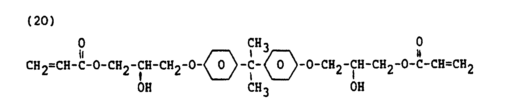
- a suitable synthetic resin layer can be obtained by exposing a UV-light curable composition comprising 60 parts by weight of a compound of formula 19, 36 parts by weight of a compound of formula 20 and 4 % by weight of an initiator to light, and hence polymerising it.
- various dichroic colorants can be used.
- three or more dichroic colorants can be used which each have a different absorption characteristic and, for example, which have an absorption wavelength area in respectively, the blue, red and green part, of the spectrum.
- white light can be completely or substantially polarised.
- non-polarised light is irradiated in a direction perpendicular to the main faces of the filter. This direction is indicated by arrow 5.
- the polarisation component of said light which components extends in a direction parallel to the direction of orientation (arrows 4) of the molecules of the dichroic colorant or colorants used is absorbed.
- the polarisation component which extends perpendicularly to the direction of orientation is passed, so that polarised light having a predetermined direction of polarisation is obtained.
- reference numerals 10 and 11 denote two parallel disposed glass plates. Said plates 10 and 11 are interconnected by a peripherally arranged sealing ring 12 which is composed of, for example, an adhesive or a synthetic resin ring which is bonded to said plates by means of an adhesive.
- a liquid crystalline cell medium 14 is present in a cellular space 13 which is enclosed by the plates 10, 11 and the ring 12, said cell medium containing 1 % by weight of a chiral substance having the following formula - and for the rest a liquid crystalline material comprising one or more compounds of the following formulae:
- Such a material is marketed by Hoffman-la Roche under the tradename ROTN 3010.
- the plates 10 and 11 have transparent strip-shaped electrodes 15 and 16 which cross each other at right angles and form a matrix of switching elements.
- the electrodes are manufactured from, for example, indium-tin oxide (ITO).
- each filter comprises a substrate plate 1 and a liquid crystalline layer 2 (Fig. 1). It It is alternatively possible to use only the liquid crystalline layer 2 of the optical filter. In this case, plate 10 with electrode 15 serves as the substrate plate for the liquid crystalline layer. The same applies to plate 11 with electrode 16. It is alternatively possible to arrange the optical polarisation filters 17 and 18 between the glass plates 10 and 11 and the electrodes 15 and 16, respectively. Finally, orientation layers 19 and 20, which are manufactured from obliquely vapour-deposited SiO, are applied to the polarisation filters 17 and 18, respectively.
- the liquid crystalline cell medium 14 has a 270° twist across the cell thickness. Twist is to be understood to mean herein the rotation of the average direction (director) of the longitudinal axis of the molecules of the liquid crystalline compound across the cell thickness, i.e. over the distance between the orientation layers 19 and 20.
- the display according to Fig. 2 operates as follows.
- the display is irradiated by non-polarised white light 21 which is emitted by a lamp 22.
- Said light 21 passes through the transparent (glass) plate 10, the transparent electrode 15 and subsequently the polarisation filter 17.
- the light 11 is polarised when it passes through the polarisation filter.
- the polarised light passes through the orientation layer 19 and reaches the liquid cell medium 14.
- the further propagation of the light through the cell medium 14 depends on the voltage pattern of the electrodes 15, 16.
- An electric voltage pattern which is representative of the image to be displayed is applied to said electrodes which, according to a customary construction, are built up of column electrodes 15 and row electrodes 16 which cross each other at right angles and which can individually be driven electrically.
- the cell medium In those parts of the cell medium, located between the electrodes 15, 16, where no electric field prevails, i.e. no voltage at the relevant electrodes, or where a weak electric field prevails which is below a threshold value, the cell medium exhibits the 270° twisted configuration.
- the molecules of the liquid crystalline cell medium 14 follow this twisted configuration.
- the molecules of the liquid crystalline material have a tilted orientation at the interface of the medium 14 and the substrate wall, the tilt angle being approximately 20° relative to the surface of the substrate plate 10 or 11.
- the tilt angle of the molecules decreases to a few degrees.
- said twisted configuration having a tilted orientation will hereinafter be referred to as the non-energised or voltageless situation.
- the molecules of the cell medium 14 will be oriented according to the field lines and exhibit an orientation which extends perpendicularly or substantially perpendicularly to the electrodes 15, 16 and, hence, to the substrate plates 10, 11. This perpendicular orientation will hereinafter be referred to as the voltage-conveying or energised situation.
- the linearly polarised light is changed into elliptically polarised light as a result of birefringence. This change depends on the wavelength.
- the light passes through the orientation layer 20, the polarisation filter 18, the electrodes 16 and the plate 11.
- the colour of said light depends on the position of the polarisation filter 18 ( analysesr) relative to the polarisation filter 17. In the case of a parallel position a blue colour effect is obtained, i.e. blue light.
- the elliptically polarised light has a yellow colour effect in the non-energised situation.
- no light is passed as a result of the crossed position of the polarisers 17, 18.
- the result is an image having a yellow-black contrast.
- the drawing comprises 2 Figures, in which
Abstract
Description
- II. Detailed description of the invention
- Polarisation filters for use in optical systems and in particular in liquid crystalline displays.
- In United States Patent Specification US 4 810 433, a method of producing a uniaxially oriented optically transparent film is described. Firstly, the surface of a support plate is oriented. A mixture comprising at least two liquid crystalline monomers and a photopolymerisation initiator is provided on said plate. The monomers have a functional, polymerisable group in the molecule. The monomers used correspond to the formula


- The mixture may comprise a dichroic colorant, a UV absorber and a spacer such as glass grains. Subsequently, the monomers are polymerised in the liquid crystalline state by exposing them to radiation using UV light or visible light.
- The oriented film described hereinabove under b) has the disadvantage that the orientation is completely lost when the temperature is increased to a level above the transition temperature nematic- isotropic. Consequently, the film is not temperature resistant, not even when the film is heated for a short period, for example, during the production process.
- The problem described under c) is solved by the invention which provides the following method:
- A method of manufacturing a polarisation filter, in which a mixture of a liquid crystalline monomer and a dichroic colorant is oriented on a substrate, and the monomer is polymerised by exposing it to uniform radiation, characterized in that a monomer is used which corresponds to the formula

- R is a hydrogen atom or a methyl group, and
- M is a mesogenic group comprising at least a phenyl group and/or a cyclochexyl group so that the monomer as a whole acquires a nematic or smectic phase.
- The polarisation filter obtained according to the invention comprises an oriented layer having an ordered network of a polymerised and oriented monomer in which the dichroic colorant which is dissolved or finely dispersed therein is oriented also. The polarisation filter manufactured according to the invention is thermostable. The orientation is preserved even when it is heated to very high temperatures of, for example, 350°C.
- The bridging group B shown in formula 1 is, for example, a group which can be represented by one of the following formulae:


- Examples of the nematic or smectic liquid crystalline group M shown in formula (1) are represented by the following formulae:


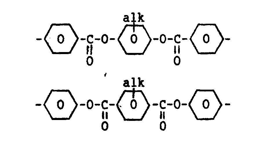
- wherein alk represents an alkyl group having 1-6 carbon atoms.
- In a favourable embodiment of the method according to the invention, a monomer is used which corresponds to formula (2)
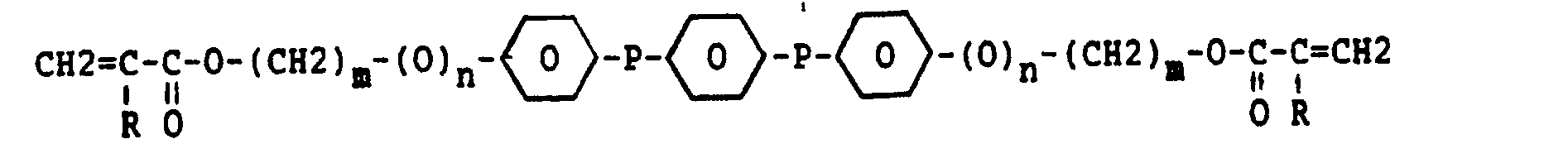
- wherein m is equal to 1-15
- n is equal to 0 or 1
- R is a hydrogen atom or a methyl group, and
- P is the group

- or the group

- By virtue of the high mobility of the molecules and the character of the liquid crystalline group incorporated in said molecules, this monomer can be oriented very rapidly. The polymerisation of the monomer by exposing it to radiation using, for example, UV light is also carried out very rapidly.
- Examples of effective monomers are represented by the following formulae:


- In method according to the invention, the liquid crystalline monomer can be oriented in different manners. For example, the substrate surface on which the mixture of the liquid crystalline monomer and the dichroic colorant is provided can be rubbed in one direction, for example by using a velvet cloth. Consequently, the molecules and the liquid crystalline monomer compound are oriented in the direction of rubbing. In this case, the orientation of the molecules extends in a direction parallel to the substrate surface. As a result of the orientation of the monomer molecules, the molecules of the dichroic colorant will also be oriented in the same direction. This phenomenon is termed guest-host effect.
- A suitable material which can be oriented by rubbing is polyimide. Thus, the substrate used in the method according to the invention can be manufactured from polyimide or covered with a layer of polyimide. In the latter case, for example, a glass plate may be used as a support for the polyimide.
- In a preferred embodiment of the method according to the invention, the mixture of the liquid crystalline monomer and the dichroic colorant which is provided on the substrate is oriented under the influence of an external field of force, in particular a magnetic field or an electric field. This has several advantages. Firstly, there is freedom of choice of a substrate. Secondly, a very rapid orientation is possible. Thirdly, any direction of orientation can be attained by the selection of the field direction of the magnetic or electric field applied.
- Obviously, orientation is possible only when the monomer is in the liquid crystalline phase. This is a matter of temperature. The layer composed of the mixture of the monomer and the dichroic colorant must be heated to a temperature which is higher than the transition temperature from crystalline to liquid crystalline and lower than the transition temperature from liquid crystalline to isotropic. Alternatively, the monomer may be processed, after it has been melted, in the undercooled phase at temperatures below the melting point.
- After the monomer molecules and, hence, the colorant molecules are oriented, the monomer molecules are polymerised. Polymerisation takes place by irradiation using light, in particular UV light. To this end, the monomer composition to be polymerised comprises a photoinitiator in a quantity from 0.5-5 % by weight. Examples of suitable photoinitiators are represented by the formulae
-

- The concentration of the dichroic colorant in the mixture of the monomer and the colorant is not restricted within narrow limits. A suitable concentration ranges from 1-10 % by weight and, typically, from 1-4 % by weight. Examples of suitable dichroic colorants are represented by the following formulae:


- The colorant represented by formula (16) is a UV-light absorbing colorant. It might be assumed that due to the presence of such a colorant, the monomer molecules cannot or only partly be polymerised by means of UV light. This assumption is incorrect. The colorant molecules are oriented, so that polymerisation of the monomer by UV light is very well possible since the film remains transparent to the common rays.
- For further dichroic colorants reference is made to Mol. Cryst. Lig. Cryst., 1979, Vol. 55, pp. 1-32.
- The invention further relates to a novel polarisation filter which is obtained by using the above-described method. Said polarisation filter according to the invention is characterized in that it comprises a substrate which is provided on one side with a layer of an oriented and polymerised monomer which contains a dichroic colorant, said monomer corresponding to the formula

- R is a hydrogen atom or a methyl group, and
- M is a mesogenic group comprising at least a phenyl group and/or a cyclohexyl group, so that the monomer as a whole acquires a nematic or smectic phase.
- The invention also relates to a liquid crystalline display comprising two transparent wall portions which extend parallel to each other and which are interconnected along the periphery by means of a seal, each wall portion being provided with one or more transparent electrodes on the inside and the space bounded by the wall portions and the seal containing a liquid crystalline medium, characterized in that at least one of the two wall portions is also provided with a polarisation filter on the inside, which filter contains a layer of an oriented and polymerised liquid crystalline monomer in which a dichroic colorant is incorporated, said monomer corresponding to the formula

- wherein B is a bridging group, R is a hydrogen atom or a methyl group, and
- M is a mesogenic group which comprises at least a phenyl group and/or a cyclohexyl group, so that the monomer as a whole acquires a nematic or smectic phase.
- The display according to the invention has the advantage that the above-defined filter is arranged on the inside of the wall portions of the display. This is possible because by virtue of the above-described network structure the filter is resistant to possible attack by the liquid crystalline medium present in the display. A polarisation filter which is arranged on the inside is totally screened from the surroundings and, hence, it is protected against possible atmospheric contaminations such as dust particles. A display having (a) polarisation filter(s) arranged on the inside can also be manufactured in a simple manner.
- The invention will be explained in greater detail by means of the following exemplary embodiment and with reference to the accompanying drawing.
- A substrate plate 1 of glass having a thickness of 0.5 mm is provided with a
layer 2 of a mixture comprising 96 % by weight of a liquid crystalline monomer compound of formula (5), 2.5 % by weight of a dichroic colorant of formula (17) and 1-5 % by weight of an initiator of formula (14). Saidlayer 2 is applied by means of spin coating and has a thickness of, for example, 10 µm.Layer 2 is heated to a temperature in excess of the transition temperature (107°C) from the crystalline to the liquid crystalline (nematic) phase. A suitable temperature is 115°C. The temperature used must be lower than the transition temperature from the liquid crystalline to the isotropic phase, which in the present example is 165°C. The molecules of the liquid crystalline monomer compound and, hence, also the molecules of the dichroic colorant are oriented in a direction which extends parallel to the magnetic field direction by means of a magnetic field of 10 k.Gauss whose field direction is indicated byarrow 3. Said magnetic field direction is indicated by arrows 4. Subsequently,layer 2 is irradiated over its entire surface by means of UV, which UV light is generated by a low-pressure mercury vapour lamp having a power of 5 mW/cm2. The exposure time is several minutes. During exposure the temperature is held at 115°C and the magnetic field is also maintained. The oriented molecules of the liquid crystalline monomer compound are polymerised as a result of said exposure, so that the desired orientation is fixed. The orientation of the molecules of the dichroic colorant is also fixed as a result of the polymerisation of the liquid crystalline monomer molecules. A network of liquid crystalline polymer molecules is formed, such that the oriented colorant molecules are incorporated therein while preserving their direction of orientation. The polarisation filter according to the invention, as shown in Fig. 1, is manufactured as described hereinbefore. - Instead of orienting the liquid crystalline monomer molecules by applying a magnetic field or an electric field, as described above, another method of obtaining the desired orientation can alternatively be used. For this purpose, a substrate is used whose surface, to which the liquid crystalline monomer is applied at a later stage, is rubbed in one direction with, for example, a velvet cloth. As a consequence hereof, the molecules of the substrate surface are oriented in the direction of rubbing.
- The above mixture of the liquid crystalline monomer compound and the dichroic colorant is applied to the surface thus treated. The molecules of the monomer compound and the colorant are oriented in the initial direction of rubbing. A suitable substrate is manufactured from polyimide. The substrate may also comprise a support plate of, for example, glass or quartz on which a polyimide layer or possibly another synthetic resin layer may be oriented, for example, by rubbing. A suitable synthetic resin layer can be obtained by exposing a UV-light curable composition comprising 60 parts by weight of a compound of
formula 19, 36 parts by weight of a compound offormula 20 and 4 % by weight of an initiator to light, and hence polymerising it.
- In
layer 2 of the optical filter according to the invention, various dichroic colorants can be used. For example, three or more dichroic colorants can be used which each have a different absorption characteristic and, for example, which have an absorption wavelength area in respectively, the blue, red and green part, of the spectrum. By using such mixtures of dichroic colorants in the polarisation filter according to the invention, white light can be completely or substantially polarised. - When the polarisation filter is used, non-polarised light is irradiated in a direction perpendicular to the main faces of the filter. This direction is indicated by arrow 5. The polarisation component of said light, which components extends in a direction parallel to the direction of orientation (arrows 4) of the molecules of the dichroic colorant or colorants used is absorbed. The polarisation component which extends perpendicularly to the direction of orientation is passed, so that polarised light having a predetermined direction of polarisation is obtained.
- In Fig. 2,
reference numerals plates ring 12 which is composed of, for example, an adhesive or a synthetic resin ring which is bonded to said plates by means of an adhesive. A liquidcrystalline cell medium 14 is present in acellular space 13 which is enclosed by theplates ring 12, said cell medium containing 1 % by weight of a chiral substance having the following formula


- At the surface facing the
cell medium 14, theplates electrodes - The above-described polarisation filter, referenced 17 and 18, is provided on each of the
electrodes liquid crystalline layer 2 of the optical filter. In this case,plate 10 withelectrode 15 serves as the substrate plate for the liquid crystalline layer. The same applies to plate 11 withelectrode 16. It is alternatively possible to arrange the optical polarisation filters 17 and 18 between theglass plates electrodes - The liquid
crystalline cell medium 14 has a 270° twist across the cell thickness. Twist is to be understood to mean herein the rotation of the average direction (director) of the longitudinal axis of the molecules of the liquid crystalline compound across the cell thickness, i.e. over the distance between the orientation layers 19 and 20. - The display according to Fig. 2 operates as follows.
- The display is irradiated by non-polarised
white light 21 which is emitted by alamp 22. Said light 21 passes through the transparent (glass)plate 10, thetransparent electrode 15 and subsequently thepolarisation filter 17. The light 11 is polarised when it passes through the polarisation filter. The polarised light passes through theorientation layer 19 and reaches theliquid cell medium 14. The further propagation of the light through thecell medium 14 depends on the voltage pattern of theelectrodes column electrodes 15 androw electrodes 16 which cross each other at right angles and which can individually be driven electrically. In those parts of the cell medium, located between theelectrodes - The molecules of the liquid
crystalline cell medium 14 follow this twisted configuration. In this twisted configuration of 270° across the cell, the molecules of the liquid crystalline material have a tilted orientation at the interface of the medium 14 and the substrate wall, the tilt angle being approximately 20° relative to the surface of thesubstrate plate - At those areas of the
cell medium 14 where an electric field is formed by applying an electric voltage in excess of the threshold value to theelectrodes cell medium 14 will be oriented according to the field lines and exhibit an orientation which extends perpendicularly or substantially perpendicularly to theelectrodes substrate plates - When the above-mentioned polarised light 11 passes through the part of the
cell medium 14 which is non-energised, the linearly polarised light is changed into elliptically polarised light as a result of birefringence. This change depends on the wavelength. Subsequently, the light passes through theorientation layer 20, thepolarisation filter 18, theelectrodes 16 and theplate 11. The colour of said light depends on the position of the polarisation filter 18 (analyser) relative to thepolarisation filter 17. In the case of a parallel position a blue colour effect is obtained, i.e. blue light. - When the polarised light 11 passes through the part of the cell medium which is energised, said light is passed substantially unchanged as a result of the optically isotropic situation. Consequently, when the polarisation filters 17 and 18 extend parallel to each other white light is passed and, hence, a blue-white image is obtained.
- When the polarisers 17 and 18 are arranged so that they cross each other, the elliptically polarised light has a yellow colour effect in the non-energised situation. In the energised situation no light is passed as a result of the crossed position of the
polarisers - The drawing comprises 2 Figures, in which
- Fig. 1 is a perspective top view of a polarisation filter manufactured according to the invention, and
- Fig. 2 is a cross-sectional view of a liquid crystalline display according to the invention which comprises polarisation filters according to Fig. 1.
Claims (5)

Applications Claiming Priority (2)
| Application Number | Priority Date | Filing Date | Title |
|---|---|---|---|
| NL8901167 | 1989-05-10 | ||
| NL8901167A NL8901167A (en) | 1989-05-10 | 1989-05-10 | METHOD FOR MANUFACTURING A POLARIZATION FILTER, A POLARIZATION FILTER SO OBTAINED AND A DISPLAY EQUIPPED WITH THE POLARIZATION FILTER. |
Publications (2)
| Publication Number | Publication Date |
|---|---|
| EP0397263A1 true EP0397263A1 (en) | 1990-11-14 |
| EP0397263B1 EP0397263B1 (en) | 1994-12-21 |
Family
ID=19854621
Family Applications (1)
| Application Number | Title | Priority Date | Filing Date |
|---|---|---|---|
| EP90201154A Expired - Lifetime EP0397263B1 (en) | 1989-05-10 | 1990-05-07 | Method of manufacturing a polarisation filter, a polarisation filter thus obtained and a display having such a polarisation filter |
Country Status (6)
| Country | Link |
|---|---|
| US (1) | US5024850A (en) |
| EP (1) | EP0397263B1 (en) |
| JP (2) | JP3335173B2 (en) |
| KR (1) | KR900018701A (en) |
| DE (1) | DE69015249T2 (en) |
| NL (1) | NL8901167A (en) |
Cited By (48)
| Publication number | Priority date | Publication date | Assignee | Title |
|---|---|---|---|---|
| EP0507316A2 (en) * | 1991-04-05 | 1992-10-07 | Canon Kabushiki Kaisha | Polarizing element and image display apparatus having the polarizing element |
| EP0533215A1 (en) * | 1991-11-18 | 1993-03-24 | Consortium für elektrochemische Industrie GmbH | Optical elements made from helical liquid crystal substances with reflection bands of linear polarised light, and a method for their manufacture |
| EP0559081A1 (en) * | 1992-02-27 | 1993-09-08 | Consortium für elektrochemische Industrie GmbH | Optical elements of liquid crystal substance and a method for making them |
| EP0608924A1 (en) * | 1993-01-26 | 1994-08-03 | Akzo Nobel N.V. | Homeotropically oriented liquid crystalline polymer film comprising dichroic dye |
| EP0617111A1 (en) * | 1993-03-25 | 1994-09-28 | Sumitomo Chemical Company, Limited | Optically anisotropic material, process for producing it, and retardation plate and liquid crystal display device using same |
| EP0643121A1 (en) * | 1993-09-08 | 1995-03-15 | Koninklijke Philips Electronics N.V. | Switchable cholesteric filter and luminaire having such a filter |
| EP0670506A1 (en) * | 1993-09-10 | 1995-09-06 | Nippon Kayaku Kabushiki Kaisha | Polarizer, polarizing plate and process for production thereof |
| WO1995024455A1 (en) * | 1994-03-11 | 1995-09-14 | Basf Aktiengesellschaft | Novel polymerizable liquid-crystalline compounds |
| EP0689084A1 (en) | 1994-06-24 | 1995-12-27 | F. Hoffmann-La Roche AG | Optical component |
| EP0708352A1 (en) * | 1994-10-18 | 1996-04-24 | Kureha Kagaku Kogyo Kabushiki Kaisha | Polymeric optical low-pass filter and device thereof |
| EP0704514A3 (en) * | 1994-09-26 | 1996-05-01 | Sumitomo Chemical Co | |
| WO1996038743A1 (en) * | 1995-06-02 | 1996-12-05 | Hoechst Celanese Corporation | Polarizer films comprising wholly aromatic liquid crystalline polymers and dichroic dyes |
| WO1997034862A1 (en) * | 1996-03-19 | 1997-09-25 | Merck Patent Gmbh | Reactive liquid crystal compounds |
| WO1997047467A1 (en) * | 1996-06-14 | 1997-12-18 | Hoechst Celanese Corporation | Cyclic olefin polymeric moisture barriers for polarizer applications |
| GB2315072A (en) * | 1996-07-04 | 1998-01-21 | Merck Patent Gmbh | Circular UV polariser |
| GB2315073A (en) * | 1996-07-04 | 1998-01-21 | Patent Gmbh Merck | Linear UV polariser |
| US5770107A (en) * | 1995-10-05 | 1998-06-23 | Merck Patent Gesellschaft Mit Beschrankter Haftung | Reactive liquid crystalline compound |
| GB2321717A (en) * | 1997-01-31 | 1998-08-05 | Sharp Kk | Cholesteric optical filters |
| GB2326727A (en) * | 1997-06-28 | 1998-12-30 | Sharp Kk | Liquid crystal device |
| US5861931A (en) * | 1995-10-13 | 1999-01-19 | Sharp Kabushiki Kaisha | Patterned polarization-rotating optical element and method of making the same, and 3D display |
| WO1999018475A1 (en) * | 1997-10-07 | 1999-04-15 | Robert Bosch Gmbh | Liquid crystal cell |
| EP0591508B1 (en) * | 1992-04-27 | 1999-07-07 | MERCK PATENT GmbH | Electrooptical liquid crystal system |
| EP0952478A1 (en) * | 1998-04-24 | 1999-10-27 | OIS Optical Imaging Systems, Inc. | Liquid crystal display with internal polarizer and method of making same |
| US6160597A (en) * | 1993-02-17 | 2000-12-12 | Rolic Ag | Optical component and method of manufacture |
| WO2001031370A1 (en) * | 1999-10-25 | 2001-05-03 | 3M Innovative Properties Company | Dual color guest-host polarizers and devices containing guest-host polarizers |
| WO2001031371A1 (en) * | 1999-10-25 | 2001-05-03 | 3M Innovative Properties Company | Polarizer constructions and display devices exhibiting unique color effects |
| US6514578B1 (en) | 1999-06-30 | 2003-02-04 | Merck Patent Gesellschaft Mit Beschrankter Haftung | Polymerizable mesogenic tolanes |
| US6624863B1 (en) | 1997-06-28 | 2003-09-23 | Sharp Kabushiki Kaisha | Method of making a patterned retarder, patterned retarder and illumination source |
| US6642977B2 (en) | 2001-06-20 | 2003-11-04 | 3M Innovative Properties Company | Liquid crystal displays with repositionable front polarizers |
| CN1127673C (en) * | 1995-10-31 | 2003-11-12 | 罗利克有限公司 | Liquid crystal cells for integrated optical components |
| US6924861B2 (en) | 2002-02-06 | 2005-08-02 | Merck Patent Gmbh | Birefringement film containing liquid crystal material having multi domains with splayed structure |
| EP1669431A1 (en) * | 2004-12-07 | 2006-06-14 | MERCK PATENT GmbH | Polymerizable liquid crystal formulation and polarizer |
| WO2007120458A1 (en) * | 2006-03-31 | 2007-10-25 | E. I. Du Pont De Nemours And Company | Liquid crystal compositions, polymer networks derived therefrom and process for making the same |
| EP2322958A1 (en) * | 2003-07-01 | 2011-05-18 | Transitions Optical, Inc. | Alignment facilities for optical dyes |
| US7988881B2 (en) | 2008-09-30 | 2011-08-02 | E. I. Du Pont De Nemours And Company | Multilayer laminates comprising chiral nematic liquid crystals |
| US8137582B2 (en) | 2007-08-15 | 2012-03-20 | E. I. Du Pont De Nemours And Company | Alkaloid monomers, liquid crystal compositions and polymer networks derived therefrom |
| US8334393B2 (en) | 2006-03-31 | 2012-12-18 | E I Du Pont De Nemours And Company | Chiral compounds and liquid crystal compositions and polymer networks derived therefrom |
| US8388860B2 (en) | 2007-08-15 | 2013-03-05 | E I Du Pont De Nemours And Company | Chiral compounds, liquid crystal compositions and polymer networks derived therefrom |
| US8518546B2 (en) | 2003-07-01 | 2013-08-27 | Transitions Optical, Inc. | Photochromic compounds and compositions |
| US8545984B2 (en) | 2003-07-01 | 2013-10-01 | Transitions Optical, Inc. | Photochromic compounds and compositions |
| US8582192B2 (en) | 2003-07-01 | 2013-11-12 | Transitions Optical, Inc. | Polarizing photochromic articles |
| US8698117B2 (en) | 2003-07-01 | 2014-04-15 | Transitions Optical, Inc. | Indeno-fused ring compounds |
| WO2016016156A1 (en) * | 2014-07-31 | 2016-02-04 | Rolic Ag | Encapsulation structure for an oled display incorporating antireflection properties |
| CN107703661A (en) * | 2017-09-20 | 2018-02-16 | 南京中电熊猫平板显示科技有限公司 | A kind of transparent display and preparation method thereof |
| US10000472B2 (en) | 2003-07-01 | 2018-06-19 | Transitions Optical, Inc. | Photochromic compounds |
| WO2018192896A1 (en) | 2017-04-20 | 2018-10-25 | Merck Patent Gmbh | Light modulation element |
| DE10257711B4 (en) | 2001-12-27 | 2019-09-26 | Merck Patent Gmbh | Polymerizable monocyclic compounds containing liquid crystal mixtures |
| US10519316B2 (en) | 2017-06-12 | 2019-12-31 | Samsung Display Co. Ltd. | Dye compound, polarizer using the dye compound, and display device using the dye compound |
Families Citing this family (52)
| Publication number | Priority date | Publication date | Assignee | Title |
|---|---|---|---|---|
| US5200238A (en) * | 1990-06-22 | 1993-04-06 | Loctite (Ireland) Limited | Liquid crystal display devices and method of manufacture |
| NL9001444A (en) * | 1990-06-25 | 1992-01-16 | Philips Nv | LIQUID CRYSTAL DISPLAY WITH ISO ROTATION SYMMETRICAL CONTRAST CURVES. |
| US5976638A (en) * | 1993-01-26 | 1999-11-02 | Akzo Nobel Nv | Optical recording medium comprising a homeotropically oriented liquid crystalline polymer film comprising dichroic dye |
| US5751389A (en) * | 1994-09-08 | 1998-05-12 | Sumitomo Chemical Company | Film containing oriented dye, method of manufacturing the same, and polarizer and liquid crystal display unit utilizing the same |
| US5851471A (en) * | 1996-05-16 | 1998-12-22 | The Coca-Cola Company | Method for injection molding a multi-layer preform for use in blow molding a plastic bottle |
| US5965081A (en) * | 1996-05-16 | 1999-10-12 | The Coca-Cola Company | Method of making side-gated preforms for use in blow molding plastic bottles |
| US5738918A (en) * | 1996-06-14 | 1998-04-14 | Hoechst Celanese Corp | Laminates of liquid crystalline polymeric films for polarizer applications |
| TW353145B (en) * | 1996-08-21 | 1999-02-21 | Koninkl Philips Electronics Nv | Method and device for manufacturing a broadband cholesteric polarizer |
| US5707691A (en) * | 1996-08-27 | 1998-01-13 | The Coca-Cola Company | Coating hollow containers by in-situ polymerization of monomers in bi-axially orientated form |
| US6312772B1 (en) | 1997-10-20 | 2001-11-06 | Hoechst Celanese Corporation | Multilayer laminate formed from a substantially stretched non-molten wholly aromatic liquid crystalline polymer and non-polyester thermoplastic polymer |
| US6268026B1 (en) | 1997-10-20 | 2001-07-31 | Hoechst Celanese Corporation | Multilayer laminate formed from a substantially stretched non-molten wholly aromatic liquid crystalline polymer and non-liquid crystalline polyester and method for forming same |
| US6426128B1 (en) | 1998-01-06 | 2002-07-30 | Hna Holdings, Inc. | Co-processable multi-layer laminates for forming high strength, haze-free, transparent articles and methods of producing same |
| US6245399B1 (en) * | 1998-10-14 | 2001-06-12 | 3M Innovative Properties Company | Guest-host polarizers |
| US6194481B1 (en) * | 1999-05-19 | 2001-02-27 | Board Of Regents Of The University Of Texas System | Mechanically strong and transparent or translucent composites made using zirconium oxide nanoparticles |
| US6541185B1 (en) * | 1999-09-21 | 2003-04-01 | Japan Chemical Innovation Institute | Micropattern polarized element |
| JP2001133630A (en) * | 1999-11-04 | 2001-05-18 | Fuji Photo Film Co Ltd | Anisotropic film and liquid crystal display device |
| JP3884207B2 (en) | 2000-01-20 | 2007-02-21 | インターナショナル・ビジネス・マシーンズ・コーポレーション | Liquid crystal display |
| US20040199004A1 (en) * | 2001-01-23 | 2004-10-07 | Southwest Research Institute | Novel mesogens |
| US7147800B2 (en) * | 2001-01-23 | 2006-12-12 | Southwest Research Institute | Selective ether cleavage synthesis of liquid crystals |
| US7238831B2 (en) * | 2001-01-23 | 2007-07-03 | Southwest Research Institute | Mesogens |
| EP1373184B1 (en) * | 2001-03-07 | 2005-12-07 | The University Of Texas System | Ultra-low shrinkage composite resins based on blended nematic liquid crystal monomers |
| JP3598987B2 (en) | 2001-03-28 | 2004-12-08 | セイコーエプソン株式会社 | Liquid crystal display and electronic equipment |
| US7070913B2 (en) * | 2001-05-14 | 2006-07-04 | The Hong Kong University Of Science And Technology | Photo-induced dichroic polarizers and fabrication methods thereof |
| US8576485B2 (en) | 2001-05-14 | 2013-11-05 | The Hong Kong University Of Science And Technology | Photo-induced dichroic polarizers and fabrication methods thereof |
| DE60228846D1 (en) | 2001-07-09 | 2008-10-23 | Southwest Res Inst | NEW MESOGENES, METHOD FOR THEIR PRODUCTION AND USE |
| US8545015B2 (en) | 2003-07-01 | 2013-10-01 | Transitions Optical, Inc. | Polarizing photochromic articles |
| US8089678B2 (en) | 2003-07-01 | 2012-01-03 | Transitions Optical, Inc | Clear to circular polarizing photochromic devices and methods of making the same |
| US7632540B2 (en) | 2003-07-01 | 2009-12-15 | Transitions Optical, Inc. | Alignment facilities for optical dyes |
| US7256921B2 (en) | 2003-07-01 | 2007-08-14 | Transitions Optical, Inc. | Polarizing, photochromic devices and methods of making the same |
| US7978391B2 (en) | 2004-05-17 | 2011-07-12 | Transitions Optical, Inc. | Polarizing, photochromic devices and methods of making the same |
| US9096014B2 (en) | 2003-07-01 | 2015-08-04 | Transitions Optical, Inc. | Oriented polymeric sheets exhibiting dichroism and articles containing the same |
| KR101174749B1 (en) * | 2003-11-06 | 2012-08-17 | 스미또모 가가꾸 가부시끼가이샤 | Dichroic guest-host polarizer comprising an oriented polymer film |
| US7097303B2 (en) | 2004-01-14 | 2006-08-29 | Ppg Industries Ohio, Inc. | Polarizing devices and methods of making the same |
| JPWO2005096041A1 (en) * | 2004-03-30 | 2008-02-21 | 日本化薬株式会社 | Micro pattern phase difference element |
| US20060154077A1 (en) * | 2004-07-12 | 2006-07-13 | Robert Hammond-Smith | Polymerizable liquid crystal formulation and polarizer |
| FR2876190B1 (en) * | 2004-10-04 | 2006-12-08 | Essilor Int | POLARISING OPTICAL GLASS LIGHT POLARIZING SOLID COATING COMPOSITION COMPRISING SUCH COATING, AND PROCESS FOR MANUFACTURING THE SAME. |
| CA2496235C (en) * | 2005-02-04 | 2011-11-15 | James Plant | Polarization filter utilizing brewster's angle |
| JP4766304B2 (en) * | 2005-04-21 | 2011-09-07 | 独立行政法人産業技術総合研究所 | Liquid crystalline monomer, liquid crystalline oligomer, liquid crystalline polymer and method for producing the same |
| AU2006249382A1 (en) * | 2005-05-26 | 2006-11-30 | Performance Materials Na, Inc. | High strength multilayer laminates comprising twisted nematic liquid crystals |
| US7744970B2 (en) * | 2005-05-26 | 2010-06-29 | E. I. Du Pont De Nemours And Company | Multilayer laminates comprising twisted nematic liquid crystals |
| US7736532B2 (en) | 2005-12-29 | 2010-06-15 | E.I. Du Pont De Nemours And Company | Composition for reducing the transmission of infrared radiation |
| JP5408841B2 (en) | 2006-12-29 | 2014-02-05 | 株式会社Adeka | Polymerizable compound and polymerizable composition |
| JP2009009100A (en) * | 2007-05-31 | 2009-01-15 | Sumitomo Chemical Co Ltd | Polarizing plate |
| US20090324799A1 (en) * | 2008-05-15 | 2009-12-31 | Robert Michael Hartman | Maximizing utilization of municipal sewage treatment effluents to produce a biofuel, fertilizer and/or animal feed for environmentally sustainable minded communities |
| JP5364304B2 (en) * | 2008-06-19 | 2013-12-11 | 富士フイルム株式会社 | Liquid crystal composition, light absorption anisotropic film, polarizing element, liquid crystal display device |
| JP5525213B2 (en) | 2009-08-28 | 2014-06-18 | 富士フイルム株式会社 | Polarizing film, laminate, and liquid crystal display device |
| JP5657243B2 (en) | 2009-09-14 | 2015-01-21 | ユー・ディー・シー アイルランド リミテッド | Color filter and light emitting display element |
| JP2014048428A (en) * | 2012-08-30 | 2014-03-17 | Jsr Corp | Radiation-sensitive composition, formation method of cured film for display element, cured film for display element, and display element |
| JP6689031B2 (en) | 2015-03-27 | 2020-04-28 | 日東電工株式会社 | Optical stack |
| US10035956B2 (en) | 2015-12-21 | 2018-07-31 | Industrial Technology Research Institute | Compound and liquid-crystal composition employing the same |
| US10866455B2 (en) | 2017-10-19 | 2020-12-15 | Ppg Industries Ohio, Inc. | Display devices including photochromic-dichroic compounds and dichroic compounds |
| JP7160899B2 (en) * | 2018-03-23 | 2022-10-25 | 富士フイルム株式会社 | POLARIZER, POLARIZER MANUFACTURING METHOD, LAMINATE, AND IMAGE DISPLAY DEVICE |
Citations (2)
| Publication number | Priority date | Publication date | Assignee | Title |
|---|---|---|---|---|
| EP0261712A1 (en) * | 1986-09-04 | 1988-03-30 | Koninklijke Philips Electronics N.V. | Picture display cell, method of forming an orientation layer on a substrate of the picture display cell and monomeric compounds for use in the orientation layer |
| US4810433A (en) * | 1985-09-25 | 1989-03-07 | Fuji Photo Film Co., Ltd. | Process for producing oriented film |
-
1989
- 1989-05-10 NL NL8901167A patent/NL8901167A/en not_active Application Discontinuation
- 1989-12-06 US US07/446,845 patent/US5024850A/en not_active Expired - Lifetime
-
1990
- 1990-05-07 KR KR1019900006373A patent/KR900018701A/en not_active Application Discontinuation
- 1990-05-07 DE DE69015249T patent/DE69015249T2/en not_active Expired - Lifetime
- 1990-05-07 EP EP90201154A patent/EP0397263B1/en not_active Expired - Lifetime
- 1990-05-10 JP JP11883090A patent/JP3335173B2/en not_active Expired - Lifetime
-
2000
- 2000-10-25 JP JP2000325428A patent/JP3416638B2/en not_active Expired - Lifetime
Patent Citations (2)
| Publication number | Priority date | Publication date | Assignee | Title |
|---|---|---|---|---|
| US4810433A (en) * | 1985-09-25 | 1989-03-07 | Fuji Photo Film Co., Ltd. | Process for producing oriented film |
| EP0261712A1 (en) * | 1986-09-04 | 1988-03-30 | Koninklijke Philips Electronics N.V. | Picture display cell, method of forming an orientation layer on a substrate of the picture display cell and monomeric compounds for use in the orientation layer |
Non-Patent Citations (1)
| Title |
|---|
| CHEMICAL ABSTRACTS, vol. 100, 1984, page 20, abstract no. 157259x, Columbus, Ohio, US; H. RINGSDORF et al.: "Phase behavior of dye-containing liquid crystalline copolymers and their mixtures with low molecular weight liquid crystals", & POLYM. PREPR. (AM. CHEM. SOC., DIV. POLYM. CHEM.) 1983, 24(2), 306-7 * |
Cited By (86)
| Publication number | Priority date | Publication date | Assignee | Title |
|---|---|---|---|---|
| EP0507316A3 (en) * | 1991-04-05 | 1992-10-21 | Canon Kabushiki Kaisha | Polarizing element and image display apparatus having the polarizing element |
| EP0507316A2 (en) * | 1991-04-05 | 1992-10-07 | Canon Kabushiki Kaisha | Polarizing element and image display apparatus having the polarizing element |
| EP0533215A1 (en) * | 1991-11-18 | 1993-03-24 | Consortium für elektrochemische Industrie GmbH | Optical elements made from helical liquid crystal substances with reflection bands of linear polarised light, and a method for their manufacture |
| US5301045A (en) * | 1991-11-18 | 1994-04-05 | Consortium Fur Elektrochemische Industrie Gmbh | Helical liquid crystalline element which produces linear polarized light |
| EP0559081A1 (en) * | 1992-02-27 | 1993-09-08 | Consortium für elektrochemische Industrie GmbH | Optical elements of liquid crystal substance and a method for making them |
| US5359439A (en) * | 1992-02-27 | 1994-10-25 | Consortium Fur Elektrochemische Industrie Gmbh | Optical elements based on liquid-crystalline substances with no birefringence in a non-perpendicular direction and a process for their preparation |
| EP0591508B1 (en) * | 1992-04-27 | 1999-07-07 | MERCK PATENT GmbH | Electrooptical liquid crystal system |
| EP0608924A1 (en) * | 1993-01-26 | 1994-08-03 | Akzo Nobel N.V. | Homeotropically oriented liquid crystalline polymer film comprising dichroic dye |
| US6369869B2 (en) | 1993-02-17 | 2002-04-09 | Rolic A.G. | Optical component and method of manufacture |
| US6717644B2 (en) | 1993-02-17 | 2004-04-06 | Rolic Ag | Optical component and method of manufacture |
| US6160597A (en) * | 1993-02-17 | 2000-12-12 | Rolic Ag | Optical component and method of manufacture |
| US5688436A (en) * | 1993-03-25 | 1997-11-18 | Sumitomo Chemical Company, Limited | Optically anisotropic material, process for producing it, and retardation plate and liquid crystal display device using same |
| SG85050A1 (en) * | 1993-03-25 | 2001-12-19 | Sumitomo Chemical Co | Optically anisotropic material, process for producing it, and retardation plate and liquid crystal display device using same |
| US5693253A (en) * | 1993-03-25 | 1997-12-02 | Sumitomo Chemical Company, Limited | Optically anisotropic material, process for producing it, and retardation plate and liquid crystal device using same |
| EP0617111A1 (en) * | 1993-03-25 | 1994-09-28 | Sumitomo Chemical Company, Limited | Optically anisotropic material, process for producing it, and retardation plate and liquid crystal display device using same |
| EP0643121A1 (en) * | 1993-09-08 | 1995-03-15 | Koninklijke Philips Electronics N.V. | Switchable cholesteric filter and luminaire having such a filter |
| BE1007485A3 (en) * | 1993-09-08 | 1995-07-11 | Philips Electronics Nv | SWITCHABLE cholesteric filter AND LIGHTS WITH A FILTER. |
| EP1275988A2 (en) * | 1993-09-10 | 2003-01-15 | Nippon Kayaku Kabushiki Kaisha | Polarizing element, and polarizing plate |
| EP0670506A1 (en) * | 1993-09-10 | 1995-09-06 | Nippon Kayaku Kabushiki Kaisha | Polarizer, polarizing plate and process for production thereof |
| EP0670506A4 (en) * | 1993-09-10 | 1997-12-03 | Nippon Kayaku Kk | Polarizer, polarizing plate and process for production thereof. |
| EP1275988A3 (en) * | 1993-09-10 | 2006-03-22 | Nippon Kayaku Kabushiki Kaisha | Polarizing element, and polarizing plate |
| WO1995024455A1 (en) * | 1994-03-11 | 1995-09-14 | Basf Aktiengesellschaft | Novel polymerizable liquid-crystalline compounds |
| EP0689084A1 (en) | 1994-06-24 | 1995-12-27 | F. Hoffmann-La Roche AG | Optical component |
| US5730899A (en) * | 1994-09-26 | 1998-03-24 | Sumitomo Chemical Company, Limited | Optically anisotropic film |
| EP0704514A3 (en) * | 1994-09-26 | 1996-05-01 | Sumitomo Chemical Co | |
| US5820779A (en) * | 1994-10-18 | 1998-10-13 | Kureha Kagaku Kogyo Kabushiki Kaisha | Polymeric optical low-pass filter and device thereof |
| EP0708352A1 (en) * | 1994-10-18 | 1996-04-24 | Kureha Kagaku Kogyo Kabushiki Kaisha | Polymeric optical low-pass filter and device thereof |
| US5672296A (en) * | 1995-06-02 | 1997-09-30 | Hoechst Celanese Corp. | Polarizer films comprising wholly aromatic liquid crystalline polymers and dichroic dyes |
| WO1996038743A1 (en) * | 1995-06-02 | 1996-12-05 | Hoechst Celanese Corporation | Polarizer films comprising wholly aromatic liquid crystalline polymers and dichroic dyes |
| US5770107A (en) * | 1995-10-05 | 1998-06-23 | Merck Patent Gesellschaft Mit Beschrankter Haftung | Reactive liquid crystalline compound |
| US5861931A (en) * | 1995-10-13 | 1999-01-19 | Sharp Kabushiki Kaisha | Patterned polarization-rotating optical element and method of making the same, and 3D display |
| CN1127673C (en) * | 1995-10-31 | 2003-11-12 | 罗利克有限公司 | Liquid crystal cells for integrated optical components |
| WO1997034862A1 (en) * | 1996-03-19 | 1997-09-25 | Merck Patent Gmbh | Reactive liquid crystal compounds |
| US6344154B1 (en) | 1996-03-19 | 2002-02-05 | Merck Patent Gmbh | Reactive liquid crystal compounds |
| WO1997047467A1 (en) * | 1996-06-14 | 1997-12-18 | Hoechst Celanese Corporation | Cyclic olefin polymeric moisture barriers for polarizer applications |
| US6007745A (en) * | 1996-07-04 | 1999-12-28 | Merck Patent Gesellschaft Mit Beschrankter Haftung | Linear UV polarizer |
| GB2315072A (en) * | 1996-07-04 | 1998-01-21 | Merck Patent Gmbh | Circular UV polariser |
| GB2315073B (en) * | 1996-07-04 | 2000-04-19 | Patent Gmbh Merck | Linear UV polariser |
| GB2315073A (en) * | 1996-07-04 | 1998-01-21 | Patent Gmbh Merck | Linear UV polariser |
| GB2315072B (en) * | 1996-07-04 | 2000-09-13 | Merck Patent Gmbh | Circular UV polariser |
| GB2321717A (en) * | 1997-01-31 | 1998-08-05 | Sharp Kk | Cholesteric optical filters |
| US6339464B1 (en) | 1997-01-31 | 2002-01-15 | Sharp Kabushiki Kaisha | Filter and method of making an optical device |
| US6624872B2 (en) | 1997-01-31 | 2003-09-23 | Sharp Kabushiki Kaisha | Optical radiation filter |
| US6624863B1 (en) | 1997-06-28 | 2003-09-23 | Sharp Kabushiki Kaisha | Method of making a patterned retarder, patterned retarder and illumination source |
| GB2326727A (en) * | 1997-06-28 | 1998-12-30 | Sharp Kk | Liquid crystal device |
| WO1999018475A1 (en) * | 1997-10-07 | 1999-04-15 | Robert Bosch Gmbh | Liquid crystal cell |
| US6587168B2 (en) * | 1998-04-24 | 2003-07-01 | Guardian Industries Corp. | Liquid crystal display with internal polarizer and method of making same |
| EP0952478A1 (en) * | 1998-04-24 | 1999-10-27 | OIS Optical Imaging Systems, Inc. | Liquid crystal display with internal polarizer and method of making same |
| US6124907A (en) * | 1998-04-24 | 2000-09-26 | Ois Optical Imaging Systems, Inc. | Liquid crystal display with internal polarizer and method of making same |
| US6417899B1 (en) | 1998-04-24 | 2002-07-09 | Guardian Industries Corp. | Liquid crystal display with internal polarizer and method of making same |
| US6514578B1 (en) | 1999-06-30 | 2003-02-04 | Merck Patent Gesellschaft Mit Beschrankter Haftung | Polymerizable mesogenic tolanes |
| WO2001031371A1 (en) * | 1999-10-25 | 2001-05-03 | 3M Innovative Properties Company | Polarizer constructions and display devices exhibiting unique color effects |
| US6538714B1 (en) | 1999-10-25 | 2003-03-25 | 3M Innovative Properties Company | Dual color guest-host polarizers and devices containing guest-host polarizers |
| WO2001031370A1 (en) * | 1999-10-25 | 2001-05-03 | 3M Innovative Properties Company | Dual color guest-host polarizers and devices containing guest-host polarizers |
| US6730446B2 (en) | 1999-10-25 | 2004-05-04 | 3M Innovative Properties Company | Dual color guest-host polarizers and devices containing guest-host polarizers |
| US6768586B2 (en) | 1999-10-25 | 2004-07-27 | 3M Innovative Properties Company | Polarizer constructions and display devices exhibiting unique color effects |
| US6574044B1 (en) | 1999-10-25 | 2003-06-03 | 3M Innovative Properties Company | Polarizer constructions and display devices exhibiting unique color effects |
| US6642977B2 (en) | 2001-06-20 | 2003-11-04 | 3M Innovative Properties Company | Liquid crystal displays with repositionable front polarizers |
| DE10257711B4 (en) | 2001-12-27 | 2019-09-26 | Merck Patent Gmbh | Polymerizable monocyclic compounds containing liquid crystal mixtures |
| US6924861B2 (en) | 2002-02-06 | 2005-08-02 | Merck Patent Gmbh | Birefringement film containing liquid crystal material having multi domains with splayed structure |
| US8545984B2 (en) | 2003-07-01 | 2013-10-01 | Transitions Optical, Inc. | Photochromic compounds and compositions |
| US8582192B2 (en) | 2003-07-01 | 2013-11-12 | Transitions Optical, Inc. | Polarizing photochromic articles |
| US10532997B2 (en) | 2003-07-01 | 2020-01-14 | Transitions Optical, Inc. | Photochromic compounds |
| EP2322958A1 (en) * | 2003-07-01 | 2011-05-18 | Transitions Optical, Inc. | Alignment facilities for optical dyes |
| EP2328002A1 (en) * | 2003-07-01 | 2011-06-01 | Transitions Optical, Inc. | Alignment facilities for optical dyes |
| US10532998B2 (en) | 2003-07-01 | 2020-01-14 | Transitions Optical, Inc. | Photochromic compounds |
| US10501446B2 (en) | 2003-07-01 | 2019-12-10 | Transitions Optical, Inc. | Photochromic compounds |
| US10005763B2 (en) | 2003-07-01 | 2018-06-26 | Transitions Optical, Inc. | Photochromic compounds |
| US10000472B2 (en) | 2003-07-01 | 2018-06-19 | Transitions Optical, Inc. | Photochromic compounds |
| US9309455B2 (en) | 2003-07-01 | 2016-04-12 | Transitions Optical, Inc. | Indeno-fused ring compounds |
| US8518546B2 (en) | 2003-07-01 | 2013-08-27 | Transitions Optical, Inc. | Photochromic compounds and compositions |
| US8698117B2 (en) | 2003-07-01 | 2014-04-15 | Transitions Optical, Inc. | Indeno-fused ring compounds |
| AU2005242136C1 (en) * | 2004-12-07 | 2012-03-29 | Merck Patent Gmbh | Polymerizable liquid crystal formulation and polarizer |
| CN1789289B (en) * | 2004-12-07 | 2010-07-28 | 默克专利股份有限公司 | Polymerizable liquid crystal formulation and polarizer |
| EP1669431A1 (en) * | 2004-12-07 | 2006-06-14 | MERCK PATENT GmbH | Polymerizable liquid crystal formulation and polarizer |
| US7879256B2 (en) | 2006-03-31 | 2011-02-01 | E. I. Du Pont De Nemours And Company | Liquid crystal compositions, polymer networks derived therefrom and process for making the same |
| US8334393B2 (en) | 2006-03-31 | 2012-12-18 | E I Du Pont De Nemours And Company | Chiral compounds and liquid crystal compositions and polymer networks derived therefrom |
| WO2007120458A1 (en) * | 2006-03-31 | 2007-10-25 | E. I. Du Pont De Nemours And Company | Liquid crystal compositions, polymer networks derived therefrom and process for making the same |
| US8388860B2 (en) | 2007-08-15 | 2013-03-05 | E I Du Pont De Nemours And Company | Chiral compounds, liquid crystal compositions and polymer networks derived therefrom |
| US8137582B2 (en) | 2007-08-15 | 2012-03-20 | E. I. Du Pont De Nemours And Company | Alkaloid monomers, liquid crystal compositions and polymer networks derived therefrom |
| US7988881B2 (en) | 2008-09-30 | 2011-08-02 | E. I. Du Pont De Nemours And Company | Multilayer laminates comprising chiral nematic liquid crystals |
| WO2016016156A1 (en) * | 2014-07-31 | 2016-02-04 | Rolic Ag | Encapsulation structure for an oled display incorporating antireflection properties |
| US10615376B2 (en) | 2014-07-31 | 2020-04-07 | Basf Coatings Gmbh | Encapsulation structure for an OLED display incorporating antireflection properties |
| WO2018192896A1 (en) | 2017-04-20 | 2018-10-25 | Merck Patent Gmbh | Light modulation element |
| US10519316B2 (en) | 2017-06-12 | 2019-12-31 | Samsung Display Co. Ltd. | Dye compound, polarizer using the dye compound, and display device using the dye compound |
| CN107703661A (en) * | 2017-09-20 | 2018-02-16 | 南京中电熊猫平板显示科技有限公司 | A kind of transparent display and preparation method thereof |
Also Published As
| Publication number | Publication date |
|---|---|
| US5024850A (en) | 1991-06-18 |
| JPH0321904A (en) | 1991-01-30 |
| JP2001188129A (en) | 2001-07-10 |
| KR900018701A (en) | 1990-12-22 |
| DE69015249T2 (en) | 1995-07-20 |
| DE69015249D1 (en) | 1995-02-02 |
| JP3416638B2 (en) | 2003-06-16 |
| NL8901167A (en) | 1990-12-03 |
| JP3335173B2 (en) | 2002-10-15 |
| EP0397263B1 (en) | 1994-12-21 |
Similar Documents
| Publication | Publication Date | Title |
|---|---|---|
| EP0397263B1 (en) | Method of manufacturing a polarisation filter, a polarisation filter thus obtained and a display having such a polarisation filter | |
| US5368770A (en) | Method of preparing thin liquid crystal films | |
| EP0634685B1 (en) | Liquid crystal display device and method for producing the same | |
| EP0575791B1 (en) | Liquid crystal composite layer of dispersion type, production method thereof and liquid crystal material to be used therein | |
| EP0568355B1 (en) | A liquid crystal display device and a method for manufacturing the same | |
| EP0275999B1 (en) | Liquid crystal optical device and process for its production | |
| EP0467456B1 (en) | Method of providing an orientation layer in a liquid crystalline display cell | |
| US4892392A (en) | Picture display cell and method of forming an orientation layer on a substrate of the picture display cell | |
| EP0272585B1 (en) | Liquid crystal optical device and process for its production. | |
| KR0173803B1 (en) | Lcd element and its manufacture | |
| US5528401A (en) | Liquid crystal display device having an orientation layer containing liquid crystal with a controlled orientation and method for manufacturing the same | |
| US6057008A (en) | Process for broadening cholesteric reflection bands of photopolymerizable cholesteric liquid crystals, and optical elements produced by this process | |
| EP0488116A2 (en) | Polymer dispersed liquid crystal display element and method of fabricating the same | |
| US4433900A (en) | Permanent display liquid crystal device via voltage application | |
| KR19980079983A (en) | Liquid crystal optical element and liquid crystal device having the same | |
| EP1690918B1 (en) | Liquid crystal optical element and method for its production | |
| JP3491926B2 (en) | Light modulator | |
| KR100262448B1 (en) | Electro-optical device and method for forming the same | |
| EP0586014B1 (en) | Optical modulation device | |
| JP2937684B2 (en) | Liquid crystal display device and method of manufacturing the same | |
| US6083575A (en) | Polymer dispersion type liquid crystal element and manufacturing method thereof | |
| JPH0768291B2 (en) | Copolymerizable Initiator for Improved Polymer-Dispersed Liquid Crystal Films | |
| Kani et al. | Highly oriented polysilane films prepared by the Langmuir-Blodgett technique | |
| JPH0611694A (en) | Liquid crystal optical element and its production | |
| Cui et al. | Photo-driven liquid crystal cell with high sensitivity |
Legal Events
| Date | Code | Title | Description |
|---|---|---|---|
| PUAI | Public reference made under article 153(3) epc to a published international application that has entered the european phase |
Free format text: ORIGINAL CODE: 0009012 |
|
| AK | Designated contracting states |
Kind code of ref document: A1 Designated state(s): DE FR GB NL |
|
| 17P | Request for examination filed |
Effective date: 19910513 |
|
| 17Q | First examination report despatched |
Effective date: 19921127 |
|
| GRAA | (expected) grant |
Free format text: ORIGINAL CODE: 0009210 |
|
| AK | Designated contracting states |
Kind code of ref document: B1 Designated state(s): DE FR GB NL |
|
| PG25 | Lapsed in a contracting state [announced via postgrant information from national office to epo] |
Ref country code: NL Effective date: 19941221 |
|
| REF | Corresponds to: |
Ref document number: 69015249 Country of ref document: DE Date of ref document: 19950202 |
|
| ET | Fr: translation filed | ||
| NLV1 | Nl: lapsed or annulled due to failure to fulfill the requirements of art. 29p and 29m of the patents act | ||
| REG | Reference to a national code |
Ref country code: FR Ref legal event code: CD |
|
| PLBE | No opposition filed within time limit |
Free format text: ORIGINAL CODE: 0009261 |
|
| STAA | Information on the status of an ep patent application or granted ep patent |
Free format text: STATUS: NO OPPOSITION FILED WITHIN TIME LIMIT |
|
| 26N | No opposition filed | ||
| REG | Reference to a national code |
Ref country code: FR Ref legal event code: CD |
|
| REG | Reference to a national code |
Ref country code: GB Ref legal event code: IF02 |
|
| REG | Reference to a national code |
Ref country code: GB Ref legal event code: 732E |
|
| REG | Reference to a national code |
Ref country code: FR Ref legal event code: TP |
|
| PGFP | Annual fee paid to national office [announced via postgrant information from national office to epo] |
Ref country code: DE Payment date: 20090429 Year of fee payment: 20 Ref country code: FR Payment date: 20090515 Year of fee payment: 20 |
|
| PGFP | Annual fee paid to national office [announced via postgrant information from national office to epo] |
Ref country code: GB Payment date: 20090506 Year of fee payment: 20 |
|
| REG | Reference to a national code |
Ref country code: GB Ref legal event code: PE20 Expiry date: 20100506 |
|
| PG25 | Lapsed in a contracting state [announced via postgrant information from national office to epo] |
Ref country code: GB Free format text: LAPSE BECAUSE OF EXPIRATION OF PROTECTION Effective date: 20100506 |
|
| PG25 | Lapsed in a contracting state [announced via postgrant information from national office to epo] |
Ref country code: DE Free format text: LAPSE BECAUSE OF EXPIRATION OF PROTECTION Effective date: 20100507 |