EP0396242A2 - The controlled precipitation and use of amorphous silicia from geothermal fluid or aqueous media having a silicic acid concentration - Google Patents
The controlled precipitation and use of amorphous silicia from geothermal fluid or aqueous media having a silicic acid concentration Download PDFInfo
- Publication number
- EP0396242A2 EP0396242A2 EP90303056A EP90303056A EP0396242A2 EP 0396242 A2 EP0396242 A2 EP 0396242A2 EP 90303056 A EP90303056 A EP 90303056A EP 90303056 A EP90303056 A EP 90303056A EP 0396242 A2 EP0396242 A2 EP 0396242A2
- Authority
- EP
- European Patent Office
- Prior art keywords
- silica
- fluid
- amorphous silica
- sol
- geothermal
- Prior art date
- Legal status (The legal status is an assumption and is not a legal conclusion. Google has not performed a legal analysis and makes no representation as to the accuracy of the status listed.)
- Ceased
Links
Images


Classifications
-
- B—PERFORMING OPERATIONS; TRANSPORTING
- B82—NANOTECHNOLOGY
- B82Y—SPECIFIC USES OR APPLICATIONS OF NANOSTRUCTURES; MEASUREMENT OR ANALYSIS OF NANOSTRUCTURES; MANUFACTURE OR TREATMENT OF NANOSTRUCTURES
- B82Y30/00—Nanotechnology for materials or surface science, e.g. nanocomposites
-
- C—CHEMISTRY; METALLURGY
- C01—INORGANIC CHEMISTRY
- C01B—NON-METALLIC ELEMENTS; COMPOUNDS THEREOF; METALLOIDS OR COMPOUNDS THEREOF NOT COVERED BY SUBCLASS C01C
- C01B33/00—Silicon; Compounds thereof
- C01B33/113—Silicon oxides; Hydrates thereof
- C01B33/12—Silica; Hydrates thereof, e.g. lepidoic silicic acid
-
- D—TEXTILES; PAPER
- D21—PAPER-MAKING; PRODUCTION OF CELLULOSE
- D21H—PULP COMPOSITIONS; PREPARATION THEREOF NOT COVERED BY SUBCLASSES D21C OR D21D; IMPREGNATING OR COATING OF PAPER; TREATMENT OF FINISHED PAPER NOT COVERED BY CLASS B31 OR SUBCLASS D21G; PAPER NOT OTHERWISE PROVIDED FOR
- D21H17/00—Non-fibrous material added to the pulp, characterised by its constitution; Paper-impregnating material characterised by its constitution
- D21H17/63—Inorganic compounds
- D21H17/67—Water-insoluble compounds, e.g. fillers, pigments
- D21H17/68—Water-insoluble compounds, e.g. fillers, pigments siliceous, e.g. clays
-
- D—TEXTILES; PAPER
- D21—PAPER-MAKING; PRODUCTION OF CELLULOSE
- D21H—PULP COMPOSITIONS; PREPARATION THEREOF NOT COVERED BY SUBCLASSES D21C OR D21D; IMPREGNATING OR COATING OF PAPER; TREATMENT OF FINISHED PAPER NOT COVERED BY CLASS B31 OR SUBCLASS D21G; PAPER NOT OTHERWISE PROVIDED FOR
- D21H19/00—Coated paper; Coating material
- D21H19/36—Coatings with pigments
- D21H19/38—Coatings with pigments characterised by the pigments
- D21H19/40—Coatings with pigments characterised by the pigments siliceous, e.g. clays
-
- C—CHEMISTRY; METALLURGY
- C01—INORGANIC CHEMISTRY
- C01P—INDEXING SCHEME RELATING TO STRUCTURAL AND PHYSICAL ASPECTS OF SOLID INORGANIC COMPOUNDS
- C01P2002/00—Crystal-structural characteristics
- C01P2002/02—Amorphous compounds
-
- C—CHEMISTRY; METALLURGY
- C01—INORGANIC CHEMISTRY
- C01P—INDEXING SCHEME RELATING TO STRUCTURAL AND PHYSICAL ASPECTS OF SOLID INORGANIC COMPOUNDS
- C01P2004/00—Particle morphology
- C01P2004/01—Particle morphology depicted by an image
- C01P2004/03—Particle morphology depicted by an image obtained by SEM
-
- C—CHEMISTRY; METALLURGY
- C01—INORGANIC CHEMISTRY
- C01P—INDEXING SCHEME RELATING TO STRUCTURAL AND PHYSICAL ASPECTS OF SOLID INORGANIC COMPOUNDS
- C01P2004/00—Particle morphology
- C01P2004/01—Particle morphology depicted by an image
- C01P2004/04—Particle morphology depicted by an image obtained by TEM, STEM, STM or AFM
-
- C—CHEMISTRY; METALLURGY
- C01—INORGANIC CHEMISTRY
- C01P—INDEXING SCHEME RELATING TO STRUCTURAL AND PHYSICAL ASPECTS OF SOLID INORGANIC COMPOUNDS
- C01P2004/00—Particle morphology
- C01P2004/50—Agglomerated particles
-
- C—CHEMISTRY; METALLURGY
- C01—INORGANIC CHEMISTRY
- C01P—INDEXING SCHEME RELATING TO STRUCTURAL AND PHYSICAL ASPECTS OF SOLID INORGANIC COMPOUNDS
- C01P2004/00—Particle morphology
- C01P2004/60—Particles characterised by their size
- C01P2004/62—Submicrometer sized, i.e. from 0.1-1 micrometer
-
- C—CHEMISTRY; METALLURGY
- C01—INORGANIC CHEMISTRY
- C01P—INDEXING SCHEME RELATING TO STRUCTURAL AND PHYSICAL ASPECTS OF SOLID INORGANIC COMPOUNDS
- C01P2004/00—Particle morphology
- C01P2004/60—Particles characterised by their size
- C01P2004/64—Nanometer sized, i.e. from 1-100 nanometer
-
- C—CHEMISTRY; METALLURGY
- C01—INORGANIC CHEMISTRY
- C01P—INDEXING SCHEME RELATING TO STRUCTURAL AND PHYSICAL ASPECTS OF SOLID INORGANIC COMPOUNDS
- C01P2006/00—Physical properties of inorganic compounds
- C01P2006/10—Solid density
-
- C—CHEMISTRY; METALLURGY
- C01—INORGANIC CHEMISTRY
- C01P—INDEXING SCHEME RELATING TO STRUCTURAL AND PHYSICAL ASPECTS OF SOLID INORGANIC COMPOUNDS
- C01P2006/00—Physical properties of inorganic compounds
- C01P2006/12—Surface area
-
- C—CHEMISTRY; METALLURGY
- C01—INORGANIC CHEMISTRY
- C01P—INDEXING SCHEME RELATING TO STRUCTURAL AND PHYSICAL ASPECTS OF SOLID INORGANIC COMPOUNDS
- C01P2006/00—Physical properties of inorganic compounds
- C01P2006/19—Oil-absorption capacity, e.g. DBP values
-
- C—CHEMISTRY; METALLURGY
- C01—INORGANIC CHEMISTRY
- C01P—INDEXING SCHEME RELATING TO STRUCTURAL AND PHYSICAL ASPECTS OF SOLID INORGANIC COMPOUNDS
- C01P2006/00—Physical properties of inorganic compounds
- C01P2006/60—Optical properties, e.g. expressed in CIELAB-values
-
- C—CHEMISTRY; METALLURGY
- C01—INORGANIC CHEMISTRY
- C01P—INDEXING SCHEME RELATING TO STRUCTURAL AND PHYSICAL ASPECTS OF SOLID INORGANIC COMPOUNDS
- C01P2006/00—Physical properties of inorganic compounds
- C01P2006/60—Optical properties, e.g. expressed in CIELAB-values
- C01P2006/62—L* (lightness axis)
-
- C—CHEMISTRY; METALLURGY
- C01—INORGANIC CHEMISTRY
- C01P—INDEXING SCHEME RELATING TO STRUCTURAL AND PHYSICAL ASPECTS OF SOLID INORGANIC COMPOUNDS
- C01P2006/00—Physical properties of inorganic compounds
- C01P2006/60—Optical properties, e.g. expressed in CIELAB-values
- C01P2006/63—Optical properties, e.g. expressed in CIELAB-values a* (red-green axis)
-
- C—CHEMISTRY; METALLURGY
- C01—INORGANIC CHEMISTRY
- C01P—INDEXING SCHEME RELATING TO STRUCTURAL AND PHYSICAL ASPECTS OF SOLID INORGANIC COMPOUNDS
- C01P2006/00—Physical properties of inorganic compounds
- C01P2006/60—Optical properties, e.g. expressed in CIELAB-values
- C01P2006/64—Optical properties, e.g. expressed in CIELAB-values b* (yellow-blue axis)
-
- C—CHEMISTRY; METALLURGY
- C01—INORGANIC CHEMISTRY
- C01P—INDEXING SCHEME RELATING TO STRUCTURAL AND PHYSICAL ASPECTS OF SOLID INORGANIC COMPOUNDS
- C01P2006/00—Physical properties of inorganic compounds
- C01P2006/80—Compositional purity
-
- C—CHEMISTRY; METALLURGY
- C01—INORGANIC CHEMISTRY
- C01P—INDEXING SCHEME RELATING TO STRUCTURAL AND PHYSICAL ASPECTS OF SOLID INORGANIC COMPOUNDS
- C01P2006/00—Physical properties of inorganic compounds
- C01P2006/90—Other properties not specified above
Abstract
- A. ageing the fluid to effect polymerization, thus establishing a silica sol, ageing meaning a process in which the source fluid after being made supersaturated with respect to amorphous silica is held for a period of time,
- B. optionally (prior to, with and/or after step A - preferably prior to in order to reduce arsenic adsorption) reducing the temperature of the geothermal fluid and/or sol as the case may be,
- C. inducing precipitation of amorphous silica from the sol under conditions that will provide the tertiary aggregate structure, and
- D. thereafter harvesting the amorphous silica thus precipitated.
Description
- The process described here involves precipitation and separation of amorphous silicas from geothermal water and in some cases alternative aqueous sources and use of these products, in slurry or powder form, as general purpose fillers in various industries which produce; paper, rubber, paint, plastics, adhesives, cement, agricultural chemicals and other materials requiring an additive or substrate with specific surface properties.
- It is an object of the present invention to be able to derive from geothermal fluid (naturally or artificially generated - a natural geothermal fluid can include that fluid produced by water infusion into a geothermal system) and alternative aqueous sources with sufficient silicic acid, an amorphous silica having substantially a tertiary aggregate structure, of a kind different from that which occurs naturally or at least to provide an amorphous silica product for inclusion in paper making or preparation, or for inclusion in other media.
- In this invention, the amorphous silicas are differentiated by structure into three classifications; namely, TYPES I, II and III.
- Type I silica, defined here, is precipitated from geothermal water. This silica is commonly sourced for commercial use by acid treatment of sodium silicate solutions prepared for example, by the digestion of quartz sand with sodium hydroxide.
- Type II and III silicas, defined here, may be precipitated from geothermal water or an alternate aqueous source. This alternative feedstock fluid should contain sufficient initial silicic acid and or silicate ion to allow controlled precipitation as described for geothermal water in this patent.
- Type II precipitated silica is similar in structure to a class of commercial silicas normally prepared under anhydrous conditions, known as pyrogenic "arc" silicas. The "arc" process involves the oxidation of silicon monoxide [SiO] at very high temperatures under anhydrous conditions.
- Geothermal water is normally characterized as being slightly acidic to neutral to slightly alkaline with significant concentrations of SiO₂, Na, K, Li, Ca, Mg, Rb, Cs, B, SO₄, Cl and dissolved gaseous species, e.g. CO₂, H₂S and NH₃. Almost always, arsenic is present. A detailed chemical composition is shown in table 8.
- Arsenic contamination of precipitated silicas from a geothermal source may or may not be a problem, depending on the end useage of the precipitated silica. Thus while in some applications procedures must be adopted whereby the arsenic contamination of the silica is reduced, for others it may not be necessary. For example, where amorphous silica is being precipitated for paper coating or impregnation usage, preferably the arsenic concentration is low, e.g. less than 2 mg kg⁻¹ in the paper sheet.
- The present invention is directed to controlled processes which give rise to precipitated amorphous silicas having structure different to that which occurs naturally upon cooling and deposition of silica from geothermal waters. Unlike such naturally occurring amorphous silicas the precipitated amorphous silicas of the present invention have what is termed a "tertiary aggregate structure". A "tertiary aggregate structure" is a three dimensional structure consisting of aggregates of primary particles into the secondary particles (substantially spherical) which themselves may be bridged by other accumulations of the primary particles (elongate accumulations) into the tertiary aggregate structure. Bridging silica is more frequently contained in Type I silica.
- The precipitated silicas described in this invention are classified according to the structure they possess and are identified as:
- Primary silica particles are about 1.5 nm in size and secondary particulate silica where discernible from overlap boundaries on electron micrographs, have random shapes approximately described in geometric terms by elongate ellipsoids.
- Tertiary aggregate structure of this precipitated silica comprises the former particulates and is further characterized by the presence of secondary particulate "bridging silica" composed of primary silica particles. These serve to provide infill silica which completes the tertiary aggregate structure. There is uniformity with respect to secondary particulate and bridging silica size. These structural characteristics are illustrated in figs.1 - 3.
- TYPE I precipitated silica satisfies the IUPAC classification for mesoporous material and is structurally consistent with G-type silica gels and pyrogenic "fume" silica produced from steam hydrolysis of silicon tetrachloride, e.g. Aerosils.
- Primary silica particles are about 1.5 nm in size and are aggregated to form secondary particles with definite spherical form. The diameter of these secondary particles is very variable.
- Tertiary aggregate structure comprises the former particulates and is characterized by the random packing of secondary particles of discrete form and variable size, lacking the chain-like structure of TYPE I. The presence of secondary inter-particulate bridging silica is less evident than for TYPE I, (fig. 4 & 5)
- TYPE II precipitated silica is morphologically consistent with pyrogenic silicas made under anhydrous conditions e.g. arc or plasma silicas
- Primary particle size is about 1.5 nm. Secondary particulate silica composed of the primary particles is both variable in size and shape.
- Secondary particulate silica of TYPE I and TYPE II is present.
- Tertiary aggregate structure combines characteristics of both TYPE I and TYPE II silicas. Tertiary aggregate structure is best characterized as diverse, lacking uniformity of secondary particle size and shape but having secondary particulate bridging silica present.
- The TYPE III precipitated silica may contain secondary particulate silica and bridging material with equivalent circular or cross-sectional diameters significantly larger than TYPE I precipitated silica,(fig. 6 & 7).
- The principal differences in structure for precipitated silicas considered of the present invention involve the nature of the secondary particle or particulate system and the resultant tertiary aggregate structure. Electron microscopy has not resolved a primary particle size difference for the precipitated silicas identified above.
- Secondary silica particle morphology and therefore tertiary aggregate structure, as developed from aqueous solution, can be influenced by the stage of polymerization at which a cationic agent is introduced to the process stream.
- Without wishing to be tied to any of the theories herein given to explain the present invention, the invention will now be described. The theories however, are considered to be correct.
- Accordingly in one aspect the present invention may broadly said to consist in a method of obtaining precipitated amorphous silica having substantially a tertiary aggregate structure (whether as an aqueous slurry, as a cake, powder, gel or otherwise) from a geothermal fluid (natural or induced) or for Types II and III silica, from a geothermal fluid (natural or induced) or an alternative aqueous source having a sufficient silicic acid concentration, (hereinafter all collectively "source fluid") said method comprising the steps of:
- A. ageing¹ the fluid to effect polymerisation, thus establishing a silica sol, ageing meaning a process in which the source fluid after being made supersaturated with respect to amorphous silica is held for a period of time,
- B. optionally (prior to, with and/or after step A) reducing the temperature of the source fluid and/or sol as the case may be,
- C. inducing precipitation of amorphous silica from the sol under conditions that will substantially provide the teritiary aggregate structure, and
- D. thereafter harvesting the amorphous silica thus precipitated.
- Preferably the source fluid is a geothermal fluid.
- Preferably a sufficient silica concentration is from 400 to 1400 mg kg⁻¹ expressed as silica. This preferred concentration promotes spontaneous nucleation and covers the concentration normally obtained from geothermal discharges. However higher silica concentrations do sometimes occur and processing of these fluids is similar to that described here, recognizing however that dilution and/or pH adjustment may be necessary to obtain control over the onset and rate of polymerization. A process stream with lower initial silicic acid concentrations may require lower process temperatures to promote spontaneous nucleation.
- Preferably the ageing of the fluid is for such time as is necessary for the polymerization within the fluid to provide primary particles.
- Preferably said source fluid has a silicic acid concentration outside of the range of from 400 to 1400 mg kg⁻¹ expressed as silica and dilution, pH adjustment and/or temperature adjustment is used to control the onset and rate of polymerization in the ageing step A. Where an arsenic reduction is required preferably optional step B is performed prior to any substantial performance of step A, i.e. the longer the fluid is left at higher temperature (refer figure 11), the more adsorption of arsenic occurs upon precipitation of the silica sol.
- Preferably said fluid includes arsenic values and step B is performed prior to any or any substantial performance of step A, thereby minimising adsorption of arsenic on the precipitated silica. In relation to optional step B, arsenic adsorption on to the colloidal silica surface is in part a kinetic temperature dependent relationship. Lowering the fluid temperature as soon as possible is a factor in reducing arsenic adsorption and thus ultimate arsenic concentrations in the resultant derived silica having substantially a tertiary aggregate structure.
- Preferably step A is performed at a pH from about 7 to 9.5, however where silica concentrations are sufficiently high to effect rapid polymerization lower pH's can apply i.e. 5 to 7.
- Preferably said source fluid just prior to the ageing step A is at or near 100°C and is rapidly cooled to about 30°C (except for Type II silica).
- Preferably step C involves the addition to the silica sol of coagulants which will induce precipitation of amorphous silica but without introducing excessive amounts of undesired contaminates. Most preferably the sol when precipitation is induced is slightly alkaline, (e.g. preferably a pH of from 7 to 9.5) whereupon the addition of a cation or cationic polymer is sufficient for the purposes of inducing precipitation. A preferred cation is Ca²⁺, however, Al³⁺ or Fe³⁺ can be used instead of or in conjunction with this preferred cation, provided that the use of these latter cations does not degrade the product. Another option available in inducing the precipitation from the substantially stable silica sol in conjunction with the use of the coagulants above or independent of these, is the use of an organic flocculant. It is most appropriate to use a cationic flocculant at higher pH where the silica surface is substantially negatively charged and a non-ionic flocculant at or below neutral conditions whereupon hydrogen bonding can occur.
- Preferably induction of precipitation in step C is at a pH of from 7 to 9.5 and involves the addition of a cation and/or a cationic polymer sufficient for the purposes of inducing precipitation while the sol is at a pH of from 7 to 9.5.
- Preferably the induction of precipitation in step C is with a source of Ca²⁺.
- Preferably the induction of precipitation in step C involves (i) the use of a cationic flocculant if the sol pH is sufficiently high for that to be effective in inducing precipitation or (ii) a non-ionic flocculant is the sol pH is at or below neutral pH conditions.
- Preferably step D is performed using any known separation or purification process and it may involve washing or other cleaning steps for the particles derived or may simply involve the isolation of an aqueous slurry of the amorphous silica.
- Preferably the amorphous silica product is of Type II or Type III and the source fluid has been artificially generated.
- In a further aspect the invention consists in, in a paper making process or system:
- (I) a process or system providing as a slurry, precipitated amorphous silica having substantially a tertiary aggregate structure from a geothermal fluid (natural or induced) or for Types II and III silica , geothermal fluid or an alternative aqueous source (hereinafter "source fluid") having a sufficient silicic acid concentration, the method comprising the steps of:
- (a) ageing the fluid to provide a silica sol,
- (b) optionally (prior to, with and/or after step (a)) reducing the temperature of the geothermal fluid and/or sol as the case may be,
- (c) inducing precipitation of amorphous silica from the sol under conditions that will provide substantially the tertiary aggregate structure, and
- (d) creating the aqueous slurry of the amorphous silica, and
- (II) introducing the amorphous silica slurry into the paper making system for the purposes of filling and/or coating of the paper with the silica contained therein.
- Preferably said geothermal fluid is natural.
- Preferably said silica resulting from (I) is not a Type II or III silica.
- Preferably energy is derived from the geothermal fluid (e.g. for the purpose of the general paper making process), if the geothermal resource is proximate to the papermaking plant.
- Preferably energy is primarily derived from the geothermal fluid early or substantially before the performance of step (a).
- Preferably the method of obtaining precipitated amorphous silica in the paper making process or method is in accordance with the present invention as previously defined.
- In yet a further aspect the present invention consists in precipitated amorphous silica produced by a process in accordance with the present invention.
- In still a further aspect the invention consists in paper containing substantially a tertiary aggregated amorphous silica derived from a geothermal fluid (natural or induced) or for Types II and III silica from a geothermal fluid (natural or induced) or an alternative aqueous source having a sufficient silicic acid concentration by a process comprising the steps of:
- (a) ageing a geothermal fluid having a sufficient silicic acid content to provide a silica sol,
- (b) optionally (prior to, with and/or after step (a)) reducing the temperature of the geothermal fluid and/or sol as the case may be,
- (c) inducing precipitation of amorphous silica from the sol under conditions that will provide the substantially tertiary aggregate structure.
- (d) taking or creating an aqueous slurry of the amorphous silica, and
- (e) introducing the amorphous silica slurry into the paper making system for the purposes of filling and/or coating of the paper being made with the silica contained therein to provide the paper product.
- Preferably said silica is Type I silica, Type II silica, Type III silica, or a blend of more than one of Type I, Type II and Type III silicas.
- In another aspect the invention consists in a method of obtaining precipitated amorphous silica having a Type I tertiary aggregate structure with a B.E.T. surface area in the range of 60 m²g⁻¹ and greater (whether as an aqueous slurry as a cake, powder, gel or otherwise) from a geothermal fluid (naturally or created by water infusion into a geothermal system) having a sufficient silicic acid concentration of from 400 to 1400 mg kg⁻¹ (expressed as silica), said method comprising the steps of
- (i) rapidly cooling the fluid from the time at which it reaches supersaturation with respect to amorphous silica to a lower temperature which is 30°C or above,
- (ii) ageing the fluid for a time without added coagulant present at a pH of from 5 to 9.5 to effect polymerisation thus establishing a silica sol that will lead to the Type I structure,
- (iii) inducing precipitation of amorphous silica from the silica sol by induction by an inducing agent selected from the group consisting of cationic agents, cationic coagulants, cationic flocculants, nonionic and anionic flocculants to thereby provide the type I tertiary aggregate and
- (iv) thereafter providing the silica product in the form required.
- In yet another aspect the invention consists in a method of obtaining precipitated amorphous silica having Type II tertiary aggregate structure (whether as an aqueous slurry as a cake, powder, gel or otherwise) from a geothermal fluid (naturally or created by water infusion into a geothermal system) or an alternative aqueous source having a sufficient silicic acid concentration of from 400 to 1400 mg kg⁻¹ (expressed as silica), said method comprising the steps of
- (i) optionally cooling the fluid from the time at which it reaches supersaturation with respect to amorphous silica to a temperature at which rapid precipitation can occur
- (ii) ageing the fluid for a time with added coagulant present at a pH of from 4 to 9.5 to effect rapid precipitation of the Type II structure, and
- (iii) thereafter providing the precipitated silica product in the form required.
- In yet another aspect the invention consists in a method of obtaining precipitated amorphous silica having Type III tertiary aggregate structure (whether as an aqueous slurry as a cake, powder, gel or otherwise) from a geothermal fluid (naturally or created by water infusion into a geothermal system) or an alternative aqueous source having a sufficient silicic acid concentration of from 400 to 1400 mg kg⁻¹ (expressed as silica), said method comprising the steps of
- (i) optionally cooling the fluid from the time at which it reaches supersaturation with respect to amorphous silica to a temperature at which precipitation can occur,
- (ii) ageing the fluid for a time with added coagulant present at a pH of from 5 to 9.5 to effect progressive precipitation of the Type III structure,
- (iii) completing precipitation by the addition of further coagulant and/or flocculant
- (iv) thereafter providing the precipitated silica product in the form required.
- Another aspect of the invention is Type I amorphous silica derived from a geothermal fluid by a process comprising:
- (i) rapidly cooling the fluid from the time at which it reaches supersaturation with respect to amorphous silica to a lower temperature which is 30°C or above.
- (ii) ageing the fluid for time without added coagulant at a pH of from 5 to 9.5 to effect polymerisation thus establishing a silica sol that will lead to the Type I structure,
- (iii) inducing precipitation of amorphous silica from the silica sol by induction by an inducing agent selected from the group consisting of cationic agents, cationic coagulants, cationic flocculants, nonionic and anionic flocculants to thereby provide the type I tertiary aggregate and
- (iv) thereafter providing the silica product in the form required.
- Still another aspect of the invention is precipitated amorphous silica derived from a geothermal fluid having a sufficient silicic acid (hereafter "source fluid") content by a method comprising the steps of:
- A. ageing the fluid to effect polymerisation, thus establishing a silica sol, ageing meaning a process in which the source fluid, having been made supersaturated with respect to amorphous silica is held for a period of time,
- B. optionally (prior to, with and/or after step A) reducing the temperature of the source fluid and/or sol as the case may be,
- C. inducing precipitation of amorphous silica from the sol under conditions that will provide the tertiary aggregate structure, and
- D. thereafter harvesting the amorphous silica thus precipitated.
- In still a further aspect the invention consists of a product comprising a media and a silica from a process of obtaining precipitated amorphous silica having substantially a tertiary aggregate structure (whether as an aqueous slurry, as a cake, powder, gel or otherwise) from a geothermal fluid (natural or induced) or for Types II and III silica from a geothermal fluid (natural or induced) or an alternative aqueous source having a sufficient silicic acid concentration (hereinafter all collectively "source fluid"), said method comprising the steps of:
- A. ageing the fluid to effect polymerisation, thus establishing a silica sol, ageing meaning a process in which the source fluid after being made supersaturated with respect to amorphous silica is held for a period of time,
- B. optionally (prior to, with and/or after step A) reducing the temperature of the source fluid and/or sol as the case may be,
- C. inducing precipitation of amorphous silica from the sol under conditions that will substantially provide the tertiary aggregate structure, and
- D. thereafter harvesting the amorphous silica thus precipitated
- In yet a further aspect the present invention consists in paper filled with and/or coated with precipitated amorphous silica derived from a process of the present invention.
- In another aspect the present invention consists in a paper which includes thereon and/or therein precipitated amorphous silica having substantially a tertiary aggregate structure derived from geothermal fluids.
- Preferably said precipitated amorphous silica has been obtained by a process in accordance with the present invention.
- In yet a further aspect the present invention consists in precipitated amorphous silica having substantially a tertiary aggregate structure derived from geothermal fluids. Preferably said silica has been derived from a geothermal fluid.
- Specific details of the process will now be disclosed and preferred forms of the present invention described. Precipitated silicas so produced have been successfully used, tested and/or characterized as suitable for several applications e.g. as filler, extender, opacifier, thixotropic agent, absorbent.
- (i) Figure 1 shows an enlarged view of Type I silica. The precipitated silica has the tertiary aggregate structure arising from secondary particulate silica bound by substantial amounts of bridged silica. Primary particles can be seen as small rod like entities ≈ 1.5 nm in size.
- (ii) Figure 2 & 3 are photographs of Type I precipitated silica possessing tertiary aggregate and secondary particulate structure consistent with commercial precipitated and pyrogenic silicas made in the presence of hydrogen containing compounds e.g. Aerosils, made by steam hydrolysis of SiCl₄. Each precipitate was prepared using 200 mg kg⁻¹ Ca²⁺ as coagulant, with small differences in initial silicic acid concentration, pH and temperature
- iii) Figures 4 & 5 are photographs of Type II precipitated silica possessing tertiary aggregate structure with secondary particles more clearly evident and bridging silica present to a lesser extent compared to Type I, above. Secondary particles have spherical geometry and are of variable size, consistent with pyrogenic silicas normally produced under anhydrous conditions.
- iv) Figures 6 & 7 are photographs of Type III precipitated silica. The photographs reveal a combination of the structural characteristics of Types I & II silicas. The Type I component typically contains large secondary particulate and bridging silica together with the smaller size fraction, normally contained in pure Type I silica.
- The precipitated amorphous silicas identified in this patent can attain high purity. Product with greater than 97 wt% SiO₂, on an anhydrous basis, can be achieved with relative ease. This can be further upgraded using simple washing techniques, if necessary, as the remainder comprises surface adsorbed calcium, involved in the inter-particle bridging process at this pH, which can be readily substantially removed.
- The optical properties when measured on a pure silica product can have the following L*, a* and b* values (CIE scale, illuminant D65 and 10° viewing angle from normal observer).
L*; - 97.8
a*; - 0.0
b*; - 1.3 - Type I silica has thixotropic qualities which makes it suitable in applications where thickening or reinforcement by an additive is required.
- The relatively high surface area of Types I and III silicas described in this patent, the complex structural characteristics and high pore volumes make these silicas suitable for many applications where absorptive capacity of additives is important
- For example, durable rubber products are made with the use of filler which has an open reticulated structure. Such fillers have surface area of 60 m² g⁻¹ and oil absorption capacities of ≈ 180 cm³ 100 g⁻¹. These characteristics are very similar to that obtained for several Type I silicas produced from processes described in this patent, some of which have been characterized in
section 4. - Type II silica is normally made synthetically under anhydrous conditions and using very high energy processes. It does not have the same thixotropic qualities as Type I silica. It is easily dispersed in most solid and liquid systems. Similar product is extensively used as an extender in systems employing expensive high grade filler or coatings e.g. TiO₂.
- A precipitated silica slurry can be used directly in the paper-making process, where it is incorporated into the paper sheet to improve print and optical qualities. Alternatively the solid product may be re-slurried and used similarly.
- Precipitated silicas of all classes described in this patent have been tested in paper handsheets. Addition has included both slurry and powder forms. The print quality of handsheets has been evaluated for all silicas described in process and laboratory examples of this patent as well as commercially accepted high grade fillers.
- Handsheets were manufactured using a typical newsprint pulp furnish to strict grammage tolerance of 48 ± 0.5 g m⁻² (air dry weight - AD). These were then soft calendered to a caliper of 75 ± 3 µm to obtain a representative comparison with industry standard newsprint.
- Several Type I silicas improved both the unprinted and printed optical properties of the paper above that achieved with established filler materials. Type I silica products have relatively high pore volumes and surface areas of 60 - >300 m² g⁻¹ (dried material). The tertiary network structure is present in both the slurry and powdered forms. The measured oil absorption capacities, on the dried powder are up to 280 cm³ 100g⁻¹. These qualities are very important to the effective function of the precipitated silica in paper.
- Types II & III silicas improved print quality to a lesser extent. This inferior performance is considered to arise from the less highly developed pore structure of these precipitated silicas which affects oil absorption capacities of these products in the sheet.
- Print-through decreased by as much as 0.03 units at an ash level (filler content) in the range 1 - 6 wt %. Opacity is increased by as much as 1 - 3 percentage points at ≈ 2 and 4 wt% addition respectively. Both wire and felt sides of the paper were similarly improved at two inking levels tested.
- Moderate concentrations of silicic acid are present in geothermal fluid as a result of the dissolution of silica containing minerals from the rock material in contact with the geothermally heated water.
- This fluid may be naturally discharged from surface thermal manifestations or artificially, from wells drilled to increase mass withdrawal, for whatever purpose.
- If silicic acid concentrations at surface are sufficiently high, polymerization with spontaneous homogeneous nucleation, results in critical size nuclei which rapidly grow to form primary particles.
- Spontaneous nucleation of the parent monomeric silicic acid species and subsequent growth by polymerization, forms a polymeric primary particle which attains a physical dimension of ≈ 1.5 nm.
- Under slightly acidic to neutral conditions this is best represented by the condensation reaction:

H₄SiO₄ ↔ H₃SiO₄⁻ + H⁺ - Polymerization under these conditions is considered to favour the following reaction:

- Primary particles can be observed under high power transmission electron microscopy, as shown in fig.,1.
- The primary particles constitute the colloidal silica sol initially formed. However, aggregation of these primary particles to form in part, secondary approximately spherical particles occurs throughout a period of ageing and/or when electrostatic dispersive forces are reduced through introduction of a cationic agent.
- The sol so formed after this treatment for types I and III silicas consists of secondary particles together with primary particles in various stages of aggregation (figures 1 - 3 and 6 - 7). Aggregation of and infill between secondary spheroidal particles and accretion of the same is consistent with the low solubility of this region with respect to amorphous silica, due to the negative radius of curvature occurring when any two spheroidal particles approach one another. However, for type II silica the development of secondary particles is essentially complete (figs.4 - 5).
- These stages of aggregation are consistent with the presence of secondary particulate silica of variable shape and form in the final, substantially tertiary aggregate structure produced from the destabilization and precipitation of the silica sols.
- At slightly acidic to neutral pH the silica surface is only partly ionized and as such may continue to hydrogen bond and therefore aggregate, to form larger secondary particles. At higher pH e.g 8 to 9, the primary silica particles and small aggregates of the primaries are more negatively charged. Further aggregation to develop full secondary and tertiary particulate structure requires reduction of these electrostatic repulsive forces by addition of a cationic agent.
- Silicic acid concentrations required to promote spontaneous nucleation, typically range from 400 - 1400 mg kg⁻¹, although higher concentrations do arise and can be treated similarly for the precipitation process. If control over the onset and rate of polymerization is desirable, then dilution or pH adjustment may be necessary. Once a sol is established, it may be stable or unstable, under natural conditions. This is mostly dependent on temperature, initial silicic acid concentration, existing electrolyte concentrations, average particle size and pH.
- Under most conditions the relatively dilute nature and neutral to alkaline pH of the geothermal waters, renders the sol stable. However, if precipitation/deposition does occur naturally, it is usually uncontrolled and depending upon the local environmental conditions, the resulting amorphous silica exhibits a wide range of particle sizes and shapes, (fig 8). In addition, geothermal waters contain a wide range of other constituents, present in either cation or anion form. For example, significant concentrations of Na, K, Li, Ca, Mg, Rb, Cs, B, SO₄, Cl, As, and Hg can be present. Some constituents such as arsenic, can readily adsorb on to the colloidal silica surface at particular pH and precipitation conditions, such as those that do exist naturally. The naturally precipitated silica therefore, usually contains significant quantities of arsenic, which together with the wide range in particle size and shape, often renders this naturally precipitated silica unsuitable for such commercial applications considered here.
- However, under controlled conditions, precipitation can be induced to yield a product which is suitable for commercial applications such as that described here in detail, for paper- making.
- In this controlled precipitation, primary silica particles are always the fundamental silica unit from which secondary particles and the tertiary aggregates develop.
- The secondary and tertiary particle size, surface silanol group density, chemical purity and optical quality of the silica product can be controlled. Such controlling factors include ageing time, stage at which coagulant is added, method of cooling the geothermal water, the cooling profile, precipitation temperature, pH and nature and concentration of the coagulant and/or flocculant used.
- Manipulation of these process parameters provides the suite of precipitated silicas classified as Types I, II and III.
- Figures 1 to 7 illustrate some of the more structurally different products and detailed procedures of precipitation are provided in laboratory and process examples attached.
² - "critical coagulant concentration" used in this context refers to that coagulant concentration where rapid coagulation results in precipitation. - TYPE I precipitated silica results from coagulation of silica from geothermal water in which dissolved silica species have been allowed to polymerize in the absence, or presence of an agent at a concentration lower than the "critical coagulant concentration"² which reduces the electrostatic repulsive forces e.g. primary coagulant cation, Ca²⁺. Polymerization in this case is allowed to proceed until the concentration of molybdate reactive silica is substantially reduced. The time used to effect this extent of polymerization is dependent on pH, temperature, initial silicic acid concentration and yield required.
- TYPE II precipitated silica results from coagulation of silica from geothermal water to which an agent capable of reducing the electrostatic forces of the negatively charged primary silica particles once formed, has been added prior to the occurrence of spontaneous nucleation. Spontaneous nucleation results in the formation of critical size silica nuclei and primary particles. The point of addition of coagulant depends on the degree of supersaturation of the process stream with respect to amorphous silica solubility as spontaneous nucleation can not occur until this is exceeded. The concentration of coagulant should be such as to exceed the critical coagulant concentration and to effect progressive coagulation and precipitation.
³ the induction period in this context refers to the time required for critical size nuclei to form and grow to the point where molybdate reactive silica concentration is measurably reduced. - TYPE III precipitated silica results from coagulation of silica from geothermal water to which an agent capable of reducing the electrostatic repulsive forces of the negatively charged silica particles once formed has been added during spontaneous nucleation and polymerization. The characteristics of the precipitated silica depend on the exact timing of coagulant addition relative to the rate of polymerization. For example, the existence of a significant induction period³ at low initial silicic acid concentrations enables addition of coagulant just prior to and during subsequent polymerization. This results in a greater presence of TYPE II silica in the product. If silicic acid concentrations are sufficiently high such that a very short induction period exists, a greater fraction of TYPE I silica results.
- The overall preferred process involves cooling, ageing (optional), induced precipitation and product separation stages. If a dried product is required, then a further drying and milling (grinding) stage is added, (fig.9).
- Cooling is optional if source water is at or near 100°C. The use of cooling in this case depends on the yield, arsenic concentration and type of precipitated silica to be produced. If the source water is at saturation pressure and temperature above atmospheric then cooling is used.
- Typically, a flash cooler, heat exchanger, cooling tower or ponding may be used. The cooling step is a method used to decrease induction time by increasing initial silicic acid concentrations relative to amorphous silica solubility and reduces the contamination of the precipitated silica, with arsenic, to acceptable levels.
- If this cooling step is not included in the manufacture of TYPE I precipitated silica , prior to ageing, then geothermal water initially at 100°C, may yield a silica product with arsenic concentrations as high as 500 - 600 mg kg⁻¹. If this water is rapidly cooled to about 30°C, then the arsenic concentration may be reduced to less than about 20 mg kg ⁻¹.
-
- The most important factors affecting arsenic speciation in geothermal solution with respect to this process are the initial activity of the total sulphur species and its effect on oxidation potential and also pH , temperature and flash conditions.
- The hydrogen arsenite (H₂AsO₃⁻) and thioarsenite ion (As₂S₄²⁻) are considered to be the predominant arsenic species in geothermal water at atmospheric conditions and unmodified pH.
- Experimental evidence indicates that when arsenic adsorption occurs onto the silica surface, then As(III) species are less readily adsorbed compared to As(V).
- Also, arsenic adsorption at the silica surface occurs largely during the induced coagulation steps; the extent of oxidation of As(III) to As(V) species e.g. from H₂AsO₃⁻to HAsO₄²⁻ (hydrogen arsenate ion).
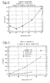
- Adsorption of arsenic species through this oxidation step is kinetically controlled and therefore temperature dependent. This is illustrated in figures 10 & 11. A significant difference in the concentration of arsenic adsorbed onto the silica surface occurs for precipitates which result from sols grown at:
- i) high temperature for a short time or low temperature for long times, and
- ii) high temperature for a long time.
- To a lesser extent, pH of solution during polymerization, or of the mother liquor after precipitation, has an influence over arsenic adsorption. Figure 12 shows arsenic concentrations for precipitates produced from the same source fluid with pH adjusted before and after precipitation. Most geothermal discharges have pH in the range 5 - 10 and more commonly 6 - 9. The allowable arsenic concentration of the final product is application dependent and may require pH control to minimise arsenic adsorption. However precipitated silicas for use as paper filler are best extracted at solution pH ≈ 7 - 9.
- An amorphous arsenic sulphide (As₂S₃) sol is established if pH is adjusted much below 7 depending upon the concentration of H₂S present upon this pH adjustment. This situation may arise by the hydrolysis of Al³⁺, when this is used to effect coagulation. The arsenic sulphide sol may on occasions be coprecipitated (refer figure 13) to an extent which compromises the otherwise high optical specifications of the precipitated silica.
- Water pH may be adjusted to 7 - 9.5 if it is more acidic than this, prior to, with and/or after cooling and ageing , in order to achieve sol destabilization at reduced coagulant concentrations. The colloidal silica sol is least stable at about
pH 9. There is no need to adjust pH should this naturally be slightly abovepH 9, if rapid polymerization (short induction period) is acceptable. The need for pH adjustment will generally vary, depending upon the particular source of geothermal water and whether or not induction time needs adjustment. -
- An ageing stage is introduced to promote polymerization if TYPE I silica is to be produced. Limited ageing occurs in the situation where TYPE II & III precipitated silicas are produced, however ageing is in the presence of coagulant in excess of the critical coagulant concentration and is for substantially shorter periods than that employed for the production of TYPE I precipitated silica. Ageing, where it is used to increase the extent of polymerization, increases yield.
- Precipitation is induced by the addition of coagulant or coagulant/flocculant combination. The concentration of coagulant attained is sufficient to exceed the critical coagulant concentration for a specified set of conditions and effect rapid coagulation and precipitation of silica.
- Cations, polycations, or positively charged colloidal particles can be used to achieve coagulation of the primary and secondary silica particulates. Not only do these function by reducing the electrostatic repulsive interaction of negatively charged, silica particle surfaces but they can also interact through proton exchange of the silanol surface.
- For example, Ca²⁺ ions are required in excess concentration to that which is accounted for by surface adsorption, to achieve particle aggregation. The Ca²⁺ ion may be obtained from a soluble calcium containing salt and serves not only to reduce the negative surface charge but can exchange for a single silanol proton thus imparting a net positive charge which provides an active site for inter-particle bridging. These simple cations are therefore surface adsorbed and remain part of the precipitate albeit in small concentrations relative to the bulk solution and may be substantially removed by mild acid washing.
- If calcium ions are used as the sole coagulant, then the concentration of the free calcium ion in solution after coagulation, should remain preferably between 50 and 1000 mg kg⁻¹. The concentration used depends on the type of precipitated silica to be produced and secondary particulate size required.
- Precipitated silica can then be removed either by filtration, as a slurry from a thickener or by a dissolved air flotation system. Alternatively it may be dried, which generally requires further milling or grinding, to yield a solid product with an appropriate tertiary aggregate particle size range required for particular commercial usage.
- If the geothermal resource is located close to a paper mill, then the slurry product can be piped to the mill for incorporation directly into the paper-making process.
- The important physical and chemical parameters which characterize the suite of precipitated silicas is provided in the following process and laboratory examples.
- The following account describes the essential engineering features of a plant to process separated water from production wells in a geothermal field with the objective to precipitate amorphous silica. As discussed elsewhere, this process could also apply to an alternative fluid source sufficiently rich in dissolved silica to form primary silica particles. Figure 14 provides a schematic plan of the process, with a mass balance for process example 1. No reference to control equipment is made.
- In this case, plant is described for a feedstock flow rate of 10 kg s⁻¹ at 100°C or slightly below. However plant can be scaled up to meet larger separated water flows, for commercial purposes.
- Precipitated silicas obtained from this process have been characterized and are described in some detail as part of laboratory examples in
section 4 of this patent. - Feedwater can be taken from a variety of sources. The main requirement is that fluid silica concentrations are sufficiently high to effect spontaneous nucleation upon cooling. However for the purpose of describing the operation of process plant and to illustrate the nature of precipitated silicas produced under different conditions , the following water sources are considered:
- i) water obtained or separated at atmospheric pressure
- ii) water separated at higher than atmospheric pressure
- Water separated at atmospheric pressure is pumped to the flash vessel, whereas fluid at higher pressure flows to the flash vessel through pressure difference. This results in flash of the feedwater which increases fluid silica concentrations and increases pH slightly as additional acidic gases are removed. Reduced fluid temperatures due to this flash also increase the degree of supersaturation with respect to amorphous silica.
- The flashed steam is condensed under vacuum by cooling water in a separate condenser vessel. The liquid from both the condenser and flash vessels exits at the bottom of the vessels via open barometric legs.
- The condenser effluent contains geothermal steam condensate and cooling water which are sent to waste.
- Flash cooling relative to alternative methods results in:
- i) rapid cooling, which reduces arsenic adsorption upon coagulation
- ii) increased supersaturation and yields upon precipitation
- The feedwater from the flash cooling vessel can either enter a covered tank, by gravity feed, or be pumped directly to the conditioners. The primary purpose of the tank is to age fluid when precipitated silica of Type I is required. When the ageing tank is employed, this also acts as a seal for the barometric leg.
- The tank is baffled to provide even ageing of the fluid. Fluid residence time is adjustable from 0 to 2 hrs by use of the bypass line or adjustment of the level control system provided for the tank. The ageing step can be bypassed if desired. Immediate or staged coagulation as discussed elsewhere in this patent can be used to produce silicas of Type II & III.
- From the ageing tank or bypass, feedwater is pumped through a static mixer to the conditioning vessels.
- Addition of primary coagulant and/or flocculant is possible from stock tanks shown in figures 14. For example calcium chloride can be introduced by way of a dosing pump with coagulant addition upstream of a centrifugal pump to ensure that rapid mixing takes place. Mixing is made uniform through the static mixer. Rapid mixing is preferable to maintain consistent secondary particulate size and is assisted by way of partial recycle of the aged feedstock stream, the precipitated silica slurry stream and/or clarified underflow from the separation plant.
- Conditioning vessels allow floc growth prior to their separation and allow floc conditioning with a mean fluid residence time range from 0 (bypass) to 10 mins.
- The conditioned feedwater flows by gravity to the Dissolved Air Flotation (DAF) tank. Pressurized, air saturated recycled liquid is injected into the feedwater flow, just upstream of the DAF tank. Precipitation of air from this water is achieved through pressure drop. The air is released as micron sized bubbles which attach to the silica flocs and effect flotation. The float is removed from the surface by a sweeper arm and pumped to the slurry storage tank.
- The air - liquid saturation plant is sized for 50% recycle and it can use either recycled DAF tank effluent or in some cases non-separated feedwater . The maximum air - liquid saturation operation pressure is 10 bar (g) which corresponds to a maximum attainable air solids ratio at full flow of approximately 0.08.
- The effluent from the DAF tank (underflow) is sufficiently low in colloidal silica to be disposed of in a manner similar to that employed for other geothermal water. However in this instance the water has been rendered more benign by virtue of heat, gas and silica removal.
- Product in this instance, is stored in a covered tank fitted with a submerged agitator. Slurry consistency should be maintained below ≈ 30 kg m⁻³ in the case of Type I silica. Above this, viscosity rises exponentially and eventually the slurry reaches gel point. Type I slurries exhibit thixotropic properties and can impart this to the medium to which they are to be applied. However for Types II & III silicas this thixotropic property is far less evident and slurry solids contents of ≈ 400 kg m⁻³ can readily be achieved.
- Alternatively, slurry is dried and ground with the use of standard engineering equipment.
-
- 2.1 Plant Feed System
Fluid is drained from the weirbox of KA 21/27 silencer into an adjacent pump pit. From the pump pit the fluid is pumped through an above ground steel pipe to the flash vessel or by-pass. The pump is a vertical centrifugal unit, which is installed in a pit at sufficient depth to provide the net positive suction head required to pump fluid at its vapour pressure.
Provision can also be made to supply the plant directly from the separated water outlet of the separators. This requires the design and installation of pipework suitable for pressurized elevated temperature service. No other revisions to plant design are necessary. - 2.2 Flash Cooler/Condenser
Pressure operating range -- 0.01 - 0.25 bar abs
Feedwater inlet temperature -- 100°C
Feedwater outlet temperature -- 45° to 100°C
Feedwater flowrate -- 10 kg s⁻¹ (max)
The flash vessel has a tangential feedwater inlet. The condenser is of the counter current tray type with the vapour inlet at the bottom of the condensing section.
Cooling water and condensed vapour from the flash cooler condenser drains from the condenser vessel through the barometric leg to a small seal tank. The water then overflows to drain.
Flashed geothermal fluid drains in a similar manner from the flash vessel to a seal tank, from which the fluid is pumped to the ageing tank. The ageing tank can also be bypassed by opening the bypass piping.
Both vessels are elevated and the liquid discharges from the bottom via open unvalved barometric legs which protect the vessels from flooding.
The vessel vacuums are maintained by using a vacuum pump. - 2.3. Ageing Tank
Volume -- 65 m³
The ageing tank is baffled to ensure even ageing time of up to 2 hours. Fluid level in the tank is controlled using an automatic level control system. - 2.4 Conditioning Tanks
Volume -- 0.85 m³
Vessel Flow Capacity -- 10 kg s⁻¹
Five conditioning vessels have been provided to allow variation of residence time. The inflow is by gravity into the top of the vessel and is baffled to minimise turbulence. The liquid flows vertically downwards to the conical bottom and discharges immediately into the DAF tank to avoid floc accumulation.
The liquid level is controlled by the liquid level in the DAF tank. - 2.5 Dissolved Air Flotation (DAF) Tank
Flow Capacity -- 10 kg s⁻¹
Product -- < 30 kg m⁻³
Float Area -- 5 kg hr⁻¹m⁻²
Volume -- 9.3 m³
Recycle Pressure -- < 10 bar g
The tank has inlet nozzles, a flow baffle, a mechanical float skimmer, an air saturator vessel, recycle pump, piping and a surfactant injection system.
The air saturator vessel and recycle pump are capable of providing a recycle rate of 50% full flow. At 7 bar (g) an air-solids ratio of at least 0.06 can be achieved. Either DAF tank effluent or in some cases conditioned feedwater is used for the air saturator feed.
The air-saturator is an unpacked column to allow conditioned feedwater to be used without the risk of clogging the saturator by flocs. The tank has a bottom liquid outlet and the pressure is controlled by a pressure regulator on the air supply.
An air space is maintained in the saturator and the liquid level control is via a level sensing device and a control loop to a by-pass valve around the recycle pump.
The DAF nozzles introduce recycled fluid directly behind the flow of fluid from the conditioning vessels. Inlet velocities are low to ensure flocs are not damaged by excessive turbulence.
DAF vessel operation is optimised by adjustment of baffle plate angle, beach length, paddle speed, recycle rate and air saturation pressure to maximise product recovery. - 2.6 Chemical Dosing
Chemical mixing and dosing equipment is provided to facilitate the preparation, storage and dosing of chemicals including calcium chloride and other primary coagulants, cationic flocculant, surfactants and pH correction (either NaOH or HCl). Chemicals can be either prepared from dry powder or bulk liquid deliveries can be made.
Dosing pumps are capable of accurate dosing rates from 0-100% of pump capacity rate.
Pump capacities are as follows:-
Coagulant -- 0.05 kg s⁻¹
Surfactant -- 0.05 kg s⁻¹
Flocculant -- 0.05 kg s⁻¹
pH correction -- 0.05 kg s⁻¹ - The following examples illustrate the use of different process and plant conditions to produce several precipitated silica products from the combined water flow of production wells KA21 and KA27 situated within the Kawerau Geothermal Resource.
- Equivalent products have been obtained from other geothermal sources e.g. Kawerau wells KA19,28 and 35, Wairakei main drain and separated water (FP#2), Ohaaki BR20, Philippines Pal14D and W102.
- The process examples are based on atmospheric discharge from the separators (initially at a temperature of ≈ 172°C) which has undergone two processes. Part of the total flow from the separators passes through a binary cycle turbine and is redischarged to the main silencer at 110°C. The remainder flows directly to the main silencer. A small increase in yield results for precipitation as a result of bypassing the binary cycle turbine.
- Separated water with a flow rate of 10 kg s⁻¹ and silica concentration of 837 mg kg⁻¹ is flash cooled from 100°C to 50°C through a flash cooling vessel to produce a feedstock water flow of 9.12 kg s⁻¹ having a pH of 9.0 (50°C) and a silica concentration of 918 mg kg⁻¹.
- Water from the flash cooler is then aged for ≈ 80 mins., prior to calcium chloride addition. A final Ca²⁺ concentration of ≈ 200 mg kg⁻¹ is attained. Solution pH decreases 0.30 - 0.50 units to ≈ 8.6 after Ca²⁺ addition, consistent with limited deprotonation of the silanol surface. Floc formation proceeds rapidly and ≈ 3 mins residence time is applied through the conditioning vessels, prior to separation.
- Fluid flows through the ageing tank, with ageing time controlled by adjustment of tank level using automatic level control on the outlet piping.
- Calcium chloride coagulant and a flocculant are introduced at a controlled rate at the exit to the ageing tanks. The fluid is mixed in an in-line static mixer before being held in the conditioning tanks to allow floc formation. Up to 200 mg kg⁻¹ silica is left in solution after formation of the silica floc.
- On introduction to the DAF tank, a minimum yield of 90% results in recovery of ≈ 20 kg hr⁻¹ (anhydrous SiO2 basis) silica slurry at concentrations varying from 15 kg m⁻³ to 30 kg m⁻³, depending on DAF operating parameters. Product is pumped to storage and agitated slowly to maintain consistent concentrations in the storage vessel.
- DAF recycle fluid is drawn from the DAF tank underflow, and pumped to the desired recycle pressure, and air is then introduced to dissolve in the recycle water.
- Excess effluent flows from the DAF underflow to drain at a rate of 8.73 kg s⁻¹, having in solution up to ≈ 200 mg kg⁻¹ silica, ≈ 200 mg kg⁻¹ Ca²⁺ and traces of flocculant (this is usually specifically adsorbed). Up to 1.71 kg hr⁻¹ of silica floc is also lost with the DAF effluent.
- Discussion of the physical and chemical characteristics of this precipitate are contained in laboratory example 1, section 4.1. The properties of precipitates produced at 65°C and 80°C are also described in the same section. This discussion also includes descriptions of precipitates, where other process variables are modified.
- Separated water at ≈ 100°C with a flow rate of 10 kg s⁻¹, initial pH ≈ 9.0 and silica concentration of 837 mg kg⁻¹ is pre-treated with calcium chloride such that the mixed solution has a Ca²⁺ concentration up to 200 mg kg⁻¹. The exact concentration is varied to achieve complete downstream precipitation with or without assistance of cationic flocculant up to 5 mg kg⁻¹
- Admixture of primary coagulant in this case is achieved by dosing the separated water stream prior to atmospheric or sub-atmospheric flash. For atmospheric, silencer feed, water is taken from the silencer outlet to the weirbox and the point of dosage is at the suction side of the hot feed pump.
- If the separated feedwater source is from the primary separators at the saturation temperature, typically 172°C, then dosage is at the flash cooler, just downstream of the pressure control valve. Flash to 100°C occurs through the flash cooler in this case.
- The silencer feedwater is pumped through the flash cooler but no condensing takes place giving a feed to the process of 10 kg s⁻¹ at a temperature of 95°C to 98°C and a silica concentration of 837 mg kg⁻¹.
- After floc development in the conditioning vessels the fluid is introduced to the DAF clarification stage where a minimum yield of 90% results in the recovery of 10.8 kg hr⁻¹ (dry weight basis). Effluent from the clarifier discharges to drain at a rate of 9.6 kg s⁻¹ having dissolved solids concentrations up to ≈ 500 mg kg⁻¹ silica, 200 mg kg⁻¹ Ca²⁺ and 5 mg kg⁻¹ flocculant. Suspended solids in the effluent have a concentration of ≈ 35 mg kg⁻¹.
- Yield may be further enhanced by precipitated slurry recycle at the point of coagulant addition. Yield from a production run is maximised by application of shear to the recycle slurry with an in-line shear mixer. This provides a particle size distribution which maximises the silica particle population introduced to enhance heterogeneous nucleation.
- The physical and chemical properties of precipitates from these treatments are discussed in section 4.2.
- Separated water with a flow rate of 10 kg s⁻¹ and a silica concentration of 837 mg kg⁻¹ is flash cooled from 100°C to 80°C through a flash cooling device to produce feedstock water with an initial pH of 8.78 (80°C), flow rate of 9.64 kg s-1 and silica concentration of 864 mg kg⁻¹.
- The feedwater is pumped directly to the conditioners having been treated with calcium chloride such that final solution concentration is up to 200 mg kg⁻¹ with respect to Ca²⁺. The exact concentration is adjusted to achieve progressive precipitation upon subsequent ageing and cooling. Fluid residence time in the system is short such that coagulant is present prior to and during the active polymerization phase.
- Primary coagulant concentrations can be lowered if lower yields are permissible but are adjusted together with cationic flocculant to achieve complete precipitation; typically, flocculant concentrations can be maintained below 5 mg kg⁻¹. Residence time in the conditioning vessels are set such that effective precipitation is achieved and the flocced fluid is then introduced to the DAF unit.
- Yield may be enhanced with the use of slurry recycle as described in example 2 above.
- On introduction to the DAF tank, a minimum yield of 90% is achieved, results in the recovery of silica at a rate of 18.3 kg hr⁻¹ at a consistency of 15 kg/m3 to 30 kg/m3 (dry weight basis). Higher consistencies can be obtained for both Type II & III silicas, e.g. ≈ 40 wt%.
- Effluent from the DAF unit discharges to drain at a rate of 9.25 kg s⁻¹, having dissolved solids concentrations of up to ≈ 400 mg kg⁻¹ silica, 200 mg kg⁻¹ Ca²⁺ and 5 mg kg⁻¹ cationic flocculant. Silica floc at a concentration up to 70 mg kg⁻¹ is also present in the DAF effluent stream.
- Dosing of the fluid with surfactant or for pH adjustment is not normally required.
- Chemical and physical characteristics of this precipitated silica are discussed in section 4.3, I.
- Physical and chemical characteristics are discussed for several laboratory examples, to illustrate:
- i) the properties of precipitated silicas produced under process conditions outlined in process examples of this patent
- ii) the influence of process variables on chemical composition and also physical and structural characteristics
- The following examples illustrate the structural and compositional differences which are obtained for precipitated silicas where ageing is applied prior to addition of coagulant which exceeds the critical coagulant concentration.
- Separated geothermal water, with a silica concentration of 850 mg kg⁻¹, is rapidly cooled under laboratory conditions by a flash cooler, in conjunction with a heat exchanger to 45 - 55°C. As discussed elsewhere other cooling devices can be used on a larger scale. Solution pH is maintained within the range 7 - 9. This water is then allowed to age from ≈ 2 to 24hrs., at which time coagulation is induced by CaCl₂.2H₂O addition such that the solution concentration is initially 200 mg kg⁻¹ in Ca²⁺ as described for the other examples discussed here.
- A milky white precipitate occurs immediately upon addition of coagulant. The time for visible floc formation to become apparent is several minutes, e.g. 2 - 4.
- Figures 1 & 2 show TEM micrographs for precipitated silica produced from fluid flash cooled to 50°C using 200 mg kg⁻¹ Ca²⁺. The secondary particulate size averages ≈ 12 nm. Tertiary aggregate structure is well developed and clearly illustrates the existence of secondary particulate and bridging silica described earlier for Type I silica.
- The untreated slurry floc size averages 90 µm and when dried and milled this particle size decreases to an average of ≈ 7 - 8 µm.
- The dry powder has a high oil absorption capacity in the range 150 - 200 cm³ 100 g-1.
- The anhydrous chemical compositions of several precipitates produced at 50°C and higher temperatures are shown in table 1.
- The most striking feature of the chemical composition of this product is the very low arsenic [As] concentrations achieved.
- The water component comprises:
- i) a - 50°C treatment, 4 - 7 wt% physisorbed, 10 wt% chemisorbed
- ii) b - 65°C treatment, 3 - 4 wt% physisorbed, 11 - 12 wt % chemisorbed
- iii) c - 80°C treatment, 2 wt% physisorbed, 17 wt% chemisorbed
- Measured BET (N₂) surface areas for the 50, 65 and 80°C treatments listed in table 1 above were 168, 179 and 118 m²g⁻¹ respectively.
- Separated geothermal water with a silica concentration of ≈ 850 mg kg⁻¹ is cooled from 100°C to 35°C over 18 hrs.
- This cooling can be achieved by allowing the geothermal fluid to stand and simulates what can be expected from natural pond cooling. pH remains unmodified if natural solution pH is maintained between pH 7 - 9. Coagulation is initiated by addition of a concentrated CaCl₂.2H₂O stock solution, at ≈ 100,000 mg kg⁻¹ to achieve a final concentration of 300 - 400 mg kg⁻¹ Ca²⁺. Introduction of the coagulant is performed according to conditions outlined in the treatment above.
- A milky white precipitate occurs immediately upon addition of the coagulant. However floc formation is not visible for several minutes, e.g. 2 - 5. Initial floc size is significantly smaller than under hotter conditions and only slowly increases. The final floc size remains smaller than that formed under hotter conditions; up to the time at which natural gravitational settling would be complete.
- At a coagulant concentration of 300 - 400 mg kg⁻¹ Ca²⁺, primary, secondary and tertiary particle size and structure are similar to that described in the treatment under hotter conditions.
- Yield can be enhanced with an increase in the Ca²⁺ concentration used, or alternatively the coagulant, flocculant combination employed.
- The secondary particulate size for a 300 Ca²⁺ treatment was ≈ 15 nm. The use of 600 mg kg⁻¹ Ca²⁺ as coagulant at these slightly lower temperatures, decreases the mean secondary particle size to ≈ 12 nm. This contributes to an increased surface area from 120 m²g⁻¹ to ≈ 150 m²g⁻¹.
- The overall structural characteristics are similar to that described for the 200 Ca²⁺ treatment, under hotter conditions (fig.2).
- The anhydrous chemical composition is shown in table 2.
- This product contains significantly less calcium and more silica than that coagulated under hotter conditions, described in
treatment 1, above. Arsenic adsorption is also low under these conditions. The extent of adsorption is largely governed by the temperature at which aging occurs, given comparable feedstock solution pH. As for all unwashed products described here, contamination by colourants such as iron is negligible.table 2. CHEMICAL COMPOSITION SiO₂ CaO Fe₂O₃ Al₂O₃ S As wt% wt% wt% wt% wt% mg kg⁻¹ 96.85 2.59 0.028 0.519 0.019 21.2 - The water component comprises:
- i) 4 wt% physi-sorbed
- ii) 7 wt% chemi-sorbed
- Yield under these conditions has been determined as 450 mg kg⁻¹ on a pure, anhydrous SiO₂ basis.
- Acid washing of this product decreased the CaO component to 0.31 wt%, while increasing the silica content to 99.19 wt%. However, upon acid washing a significant amount of arsenic sulphide has been observed to form and can reduce product whiteness.
- Separated geothermal water with a silica concentration of ≈ 850 mg kg⁻¹ , is cooled from 100°C to 80°C after 20 minutes aging. Sufficient sample volume is collected such that fluid temperature upon standing
reaches 80°C. Induced coagulation of the silica sol formed is effected by addition of a concentrated CaCl₂.2H₂O stock solution, at ≈ 100,000 mg kg⁻¹ to achieve a final solution concentration of 200 mg kg ⁻¹ Ca²⁺. - Rapid and thorough mixing of the CaCl₂ solution with the geothermal fluid is necessary to avoid localised high concentrations of coagulant, which affects secondary particle size.
- A milky-white precipitate forms immediately, upon Ca²⁺ addition and within a minute, floc formation is clearly visible.
- The stable untreated floc (tertiary aggregate) size expressed in terms of volume distribution is shown in figure 15. The slurry floc size may be influenced by surfactant addition, conditioning time and shear to meet a particle size volume distribution with mean at ≈ 8 µm, with ≦ 90% of the particle population <20 µm; this specification expressed in terms of the dispersed, dry powder.
- A Transmission Electron Micrograph shown in fig.3 indicates that the mean secondary particle size can be as high as ≈ 12 nm where this is distinguishable. The primary or ultimate particle size illustrated by the textural grain apparent in fig.,1 is ≈ 1.5 nm (15 Å). The overall structural make-up comprises spheroidal secondary particles linked via a complex mass of primary particles, which constitute the bridging silica which contributes to an intricate three dimensional silica aggregate. The bridging silica generally lacks definitive geometry (figs. 1 - 3), apart from being more elongated than the spheroidal particles and generally not exceeding the cross-sectional diameter of these.
- The anhydrous chemical compositions of several precipitates produced using these precipitation conditions is illustrated by the range in table 3.
table 3. CHEMICAL COMPOSITION SiO₂ CaO Fe₂O₃ Al₂O₃ S As wt% wt% wt% wt% wt% mg kg⁻¹ 1. 74.14 21.88 0.030 0.360 0.070 91.5 2. 89.94 9.20 0.025 0.778 0.055 74.0 - Water composition was determined as follows:
- i) physisorbed; 2 - 5 wt% for 1 & 2 respectively
- ii) chemisorbed; 13 - 17 wt% for 1 & 2 respectively
- The determination of yield for several precipitates produced under these conditions shows that ≈ 475 mg kg⁻¹ SiO2 is extractable; this assessment is based on pure anhydrous silica.
- Decantation acid washing of the precipitated silica (table 3, No1) using 0.1N HCl results in a product, with the composition given in table 4. The significant decrease in calcium concentration represented as CaO, indicates the surface adsorbed nature of the coagulant and dissolution of traces of calcium carbonate.
table 4. CHEMICAL COMPOSITION SiO₂ CaO Fe₂O₃ Al₂O₃ S As wt% wt% wt% wt% wt% mg kg⁻¹ 1. 96.91 2.47 0.017 0.581 0.019 33.1 - The unwashed precipitated silica has a surface area determined by N, adsorption (BET), of 140 m²g⁻¹. Should an increase in surface area be desired, a decantation acid wash can be performed. For example, pH adjustment of the brine in contact with slurry to ≈ 5 increases the surface area to 260 m²g⁻¹.
- The unwashed and acid washed products have high oil absorptive characteristics. The unwashed precipitated silica has an oil absorption value of ≈ 110 to 200 cm³ 100g⁻¹. The acid washed product slightly exceeds this range with oil absorption values in the range; 130 to 230 cm³ 100g⁻¹.
- Separated geothermal water at 100°C with a silica concentration of ≈ 850 mg kg⁻¹ and initial pH 8.90, is pre-treated with a known amount of 100,000 mg kg⁻¹ CaCl₂ stock solution, to achieve a final solution concentration of ≈ 200 mg kg⁻¹. Solution pH decreases ≈ 0.3 units.
⁴ - mini-silencer ; a small device used to atmospherically separate a pressurized two phase steam and water mixture. - On a laboratory scale continuous and thorough mixing of the CaCl₂ coagulant was achieved by timed, drip feed addition at the mini-silencer⁴ water outlet.
- Solution temperature decreased to 70° at the time of slurry separation.
- The solution turns milky white initially and over several minutes the precipitate is established.
- Gentle continuous stirring is employed to allow contact of developed floc with finer colloidal silica until precipitation is essentially complete; up to 10 mins.
- Figures 4 & 5 illustrate the structural characteristics of this silica which has been fully described elsewhere in this patent.
- The anhydrous chemical composition is shown in table 5:
table 5. CHEMICAL COMPOSITION SiO₂ CaO Fe₂O₃ Al₂O₃ S As wt% wt% wt% wt% wt% mg kg⁻¹ 80.9 15.6 0.42 1.19 0.14 62.9 - Water composition was determined as follows:
- i) physisorbed 1.7 wt%
- ii) chemisorbed 14.6 wt%
- Yield, without slurry recycle of modified particle size is 350 mg kg⁻¹ (pure, anhydrous basis), significantly lower than that obtained for Type I silica.
- Oil absorption capacities of the silica are significantly below that for Type I silicas, at 100 cm³ 100g⁻¹. Slurry consistencies can reach ≈ 40 wt% upon settling, in sharp contrast to Type I silica. The Type II silica has very little tendency to gel i.e it is essentially non- thixotropic.
- Separated geothermal water at 100°C and silica concentration ≈ 850 mg kg⁻¹ is pre-treated with CaCl₂ solution such that the final solution Ca²⁺ concentration is 100 mg kg⁻¹ during the polymerization phase.
- The sol is then allowed to age for 20 mins. with intermittent stirring.
- Precipitation is progressive. First the solution turns milky and becomes more turbid with time. Then, floc formation proceeds, but precipitation is not complete after ageing.
- Complete precipitation is effected with the addition of 2 - 3 mg kg⁻¹ high charge density cationic flocculant.
- Figures 6 & 7 illustrate the diversity of structure obtained with this method of preparation.
- Up to 450 mg kg⁻¹ SiO₂ (pure, anhydrous basis) is extractable.
- The anhydrous chemical composition is shown in table 6.
table 6. CHEMICAL COMPOSITION SiO₂ CaO Fe₂O₃ Al₂O₃ S As wt% wt% wt% wt% wt% mg kg⁻¹ 82.3 15.6 0.02 0.40 0.02 16.7 - Chemical compositions for products precipitated with the use of Al³⁺ and Mg²⁺ salts are provided in table 7. These were precipitated under conditions which have been described for Type I silica. Precipitates have also been prepared according to procedures for Type II & III silicas using the above coagulants and have some similar characteristics to that reported for Ca²⁺ treatments.
- If aluminium ions are present in , or introduced to the geothermal water then they may substitute for silicon in the silica unit and hence be incorporated in the overall structure. Substitution is generally minor at lower coagulation temperatures but can be significant at higher temperatures.
- As discussed elsewhere in this patent, arsenic adsorption is favoured with longer ageing at higher temperatures and also at lower pH during the coagulation step. Final pH after addition of Al³⁺ to a concentration of 40 mg kg⁻¹ was ≈ 6.3.
table 7. CHEMICAL COMPOSITION SiO₂ CaO Fe2O3 Al2O3 MgO As wt% wt% wt% wt% wt% mg kg⁻¹ 90.8 -1a 0.13 0.01 0.34 6.86 44.4 92.8 -1b 5.23 0.01 0.32 0.12 26.6 79.5 -2a 0.51 0.02 16.1 0.00 222 92.2 -2b 5.35 0.01 0.33 0.13 126 1a - 200 mg kg⁻¹ Mg²⁺ treatment.aged 2hrs.slow cooling 1b - 200 mg kg⁻¹ Mg²⁺ treatment.rapid cool.aged 2a - 40 mg kg⁻¹ Al³⁺ treatment; as for 1a 2b - 40 mg kg⁻¹ Al³⁺ treatment; as for 2a - It is significant that the magnesium treatments produced precipitated silica with high measured surface area; for samples 1a & 1b in table 7, these were 274 and 302 m²g⁻¹ respectively.
- Table 8, shows the chemical composition of atmospherically separated water from several Kawerau production wells. Examination of arsenic concentrations in water versus that which may be surface adsorbed on to precipitated silica demonstrates the preferential enrichment which can occur for the solid phase, if precipitation conditions are not optimised.
table 8. CHEMICAL COMPOSITION; KAWERAU PRODUCTION WELLS (ATMOSPHERICALLY SEPARATED WATER) DATE/SOURCE pH Li Na K Ca Fe Cl F SO₄ HCO₃ B NH₃ SiO₃ As d/m/y 25°C mg kg⁻¹ 31/8/89 KA21 8.94 7.42 840 142 1.58 0.22 1292 2.55 16 146 57.7 1.22 980 2.02 30/5/89 KA19 9.22 5.28 657 99.6 0.90 0.10 991 2.94 20 126 43.0 0.97 821 2.26 30/5/89 KA35 9.08 5.43 667 104 1.52 <.05 1017 2.54 18 139 55.2 0.99 804 1.98 18/5/89 KA21/27 MIXED 9.09 6.99 790 124 0.61 <.05 1163 2.64 20 225 47.2 1.03 923 1.91
¹ "Ageing" herein means a process in which the silica bearing fuid, having been made supersaturated with respect to amorphous silica, is held for a period of time.
The ageing time chosen prior to precipitation depends on the yield and nature of precipitated silica required for a certain application. Details of the effects of this process variable on precipitated silica extracted from geothermal water is provided elsewhere herein.
| CHEMICAL COMPOSITION | |||||
| SiO₂ | CaO | Fe₂O₃ | Al₂O₃ | S | As |
| wt% | wt% | wt% | wt% | wt% | mg kg⁻¹ |
| 90.50 a | 7.56 | 0.02 | 0.28 | 0.018 | 12.6 |
| 95.97 a | 3.56 | 0.03 | 0.43 | 0.015 | 8.6 |
| 81.36 b | 12.68 | - | - | 0.025 | 27.5 |
| 74.81 c | 22.64 | 0.01 | 0.33 | 0.047 | 56.9 |
| a - 50°C treatment | |||||
| b - 65°C treatment SEE TEXT ABOVE | |||||
| c - 80°C treatment |
Claims (43)
A. ageing the fluid to effect polymerisation, thus establishing a silica sol, ageing meaning a process in which the source fluid after being made supersaturated with respect to amorphous silica is held for a period of time,
B. optionally (prior to, with and/or after step A) reducing the temperature of the source fluid and/or sol as the case may be,
C. inducing precipitation of amorphous silica from the sol under conditions that will substantially provide the tertiary aggregate structure, and
D. thereafter harvesting the amorphous silica thus precipitated.
said silica being incorporated in, onto and/or about said media.
Applications Claiming Priority (4)
| Application Number | Priority Date | Filing Date | Title |
|---|---|---|---|
| NZ228472 | 1989-03-23 | ||
| NZ22847289A NZ228472A (en) | 1989-03-23 | 1989-03-23 | Precipitation of amorphous silica from geothermal fluid; use of silica in coating paper sheet |
| NZ232170 | 1990-01-19 | ||
| NZ232170A NZ232170A (en) | 1989-03-23 | 1990-01-19 | Precipitation of amorphous silica from geothermal fluid; use of silica in coating paper sheet |
Publications (2)
| Publication Number | Publication Date |
|---|---|
| EP0396242A2 true EP0396242A2 (en) | 1990-11-07 |
| EP0396242A3 EP0396242A3 (en) | 1991-04-10 |
Family
ID=26650845
Family Applications (1)
| Application Number | Title | Priority Date | Filing Date |
|---|---|---|---|
| EP19900303056 Ceased EP0396242A3 (en) | 1989-03-23 | 1990-03-21 | The controlled precipitation and use of amorphous silicia from geothermal fluid or aqueous media having a silicic acid concentration |
Country Status (8)
| Country | Link |
|---|---|
| US (1) | US5200165A (en) |
| EP (1) | EP0396242A3 (en) |
| JP (1) | JPH0333009A (en) |
| AU (1) | AU635525B2 (en) |
| CA (1) | CA2012954A1 (en) |
| FI (1) | FI901416A0 (en) |
| NO (1) | NO901324L (en) |
| NZ (1) | NZ232170A (en) |
Cited By (7)
| Publication number | Priority date | Publication date | Assignee | Title |
|---|---|---|---|---|
| WO1994018121A1 (en) * | 1993-02-01 | 1994-08-18 | Tasman Pulp & Paper Co. Limited | Amorphous silica, its preparation and uses |
| WO2000078675A1 (en) * | 1999-06-21 | 2000-12-28 | Geochemistry Research Limited | Metal-rich silica products from geothermal and synthetic aqueous systems |
| WO2009079047A2 (en) * | 2007-09-25 | 2009-06-25 | Lawrence Livermore National Security, Llc | Silica extraction from geothermal water |
| EP2325389A1 (en) * | 2009-11-12 | 2011-05-25 | bene_fit systems GmbH & Co. KG | Coating material for fibrous compounds |
| EP3310463A4 (en) * | 2015-06-19 | 2019-02-27 | GEO40 Limited | Method of production of a silica concentrate |
| US10626018B2 (en) | 2015-02-25 | 2020-04-21 | Geo40 Limited | Method of production of a colloidal silica concentrate |
| US11198095B2 (en) | 2014-05-23 | 2021-12-14 | Geo40 Limited | Silica products from geothermal fluids by reverse osmosis |
Families Citing this family (33)
| Publication number | Priority date | Publication date | Assignee | Title |
|---|---|---|---|---|
| US5595717A (en) * | 1989-03-23 | 1997-01-21 | Tasman Pulp & Paper Co., Limited | Controlled precipitation of amorphous silica from geothermal fluids or other aqueous media containing silicic acid |
| DE4202023A1 (en) * | 1992-01-25 | 1993-07-29 | Degussa | HAFTPROMOTER FOR RUBBER AND PLASTIC MIXTURES |
| JPH0724475A (en) * | 1993-05-13 | 1995-01-27 | Mitsubishi Materials Corp | Method for recovering silica in aqueous solution |
| BR9405616A (en) * | 1993-09-29 | 1999-09-08 | Rhone Poulenc Chimie | Process of preparation of precipitated silica, precipitated silica, and use of a silica |
| FR2710630B1 (en) * | 1993-09-29 | 1995-12-29 | Rhone Poulenc Chimie | New precipitated silicas, their preparation process and their use for reinforcing elastomers. |
| WO1997021633A1 (en) * | 1995-12-08 | 1997-06-19 | Institute Of Geological & Nuclear Sciences Limited | Inhibiting deposition of dissolved silica from brine |
| ID17651A (en) * | 1996-07-15 | 1998-01-15 | Union Oil Co | OBLIGATORS FORMING SILICATED SCALE |
| US5897849A (en) * | 1996-12-30 | 1999-04-27 | Uop Llc | Unimodal, large-pore silicas by hydrothermal treatment of silicia powders |
| JP3303070B2 (en) * | 1998-04-02 | 2002-07-15 | 三菱マテリアル株式会社 | Apparatus and method for recovering suspended solids from geothermal hot water |
| US6537796B1 (en) | 1999-05-14 | 2003-03-25 | Brookhaven Science Associates, Llc | Conversion of geothermal waste to commercial products including silica |
| US6758976B2 (en) * | 2001-10-25 | 2004-07-06 | Imc Global Operations Inc. | Simplified purification of phosphoric acid plant pond water |
| US7316787B2 (en) * | 2004-09-17 | 2008-01-08 | General Electric Company | Methods for controlling silica scale in aqueous systems |
| US7855313B2 (en) * | 2005-02-28 | 2010-12-21 | Energysolutions, Inc. | Low-temperature solidification of radioactive and hazardous wastes |
| US8862200B2 (en) * | 2005-12-30 | 2014-10-14 | DePuy Synthes Products, LLC | Method for determining a position of a magnetic source |
| US10190030B2 (en) | 2009-04-24 | 2019-01-29 | Alger Alternative Energy, Llc | Treated geothermal brine compositions with reduced concentrations of silica, iron and lithium |
| US8741256B1 (en) | 2009-04-24 | 2014-06-03 | Simbol Inc. | Preparation of lithium carbonate from lithium chloride containing brines |
| US9034294B1 (en) | 2009-04-24 | 2015-05-19 | Simbol, Inc. | Preparation of lithium carbonate from lithium chloride containing brines |
| US8597521B1 (en) | 2009-06-24 | 2013-12-03 | Simbol Inc. | Selective removal of silica from silica containing brines |
| US9051827B1 (en) | 2009-09-02 | 2015-06-09 | Simbol Mining Corporation | Selective removal of silica from silica containing brines |
| US8637428B1 (en) | 2009-12-18 | 2014-01-28 | Simbol Inc. | Lithium extraction composition and method of preparation thereof |
| US10683563B2 (en) | 2009-06-24 | 2020-06-16 | Terralithium Llc | Treated geothermal brine compositions with reduced concentrations of silica, iron and manganese |
| US9650555B2 (en) | 2009-06-24 | 2017-05-16 | Simbol, Inc. | Treated geothermal brine compositions with reduced concentrations of iron and silica |
| US10935006B2 (en) | 2009-06-24 | 2021-03-02 | Terralithium Llc | Process for producing geothermal power, selective removal of silica and iron from brines, and improved injectivity of treated brines |
| US9644866B2 (en) | 2009-06-24 | 2017-05-09 | Simbol, Inc. | Treated brine compositions with reduced concentrations of potassium, rubidium, and cesium |
| US9644126B2 (en) | 2009-06-24 | 2017-05-09 | Simbol, Inc. | Treated geothermal brine compositions with reduced concentrations of silica, iron, and zinc |
| EP2749535B1 (en) | 2010-02-17 | 2019-07-31 | All American Lithium LLC | Processes for preparing highly pure lithium carbonate and other highly pure lithium containing compounds |
| JP6164077B2 (en) * | 2013-12-18 | 2017-07-19 | 三菱マテリアル株式会社 | Synthetic amorphous silica powder and method for producing the same |
| US10604414B2 (en) | 2017-06-15 | 2020-03-31 | Energysource Minerals Llc | System and process for recovery of lithium from a geothermal brine |
| JP6466615B2 (en) * | 2017-06-30 | 2019-02-06 | 富士化学株式会社 | Solidification material for ground injection |
| JP6796305B1 (en) * | 2020-02-18 | 2020-12-09 | 強化土エンジニヤリング株式会社 | Ground injection method and ground injection material |
| JP7072818B1 (en) * | 2020-12-02 | 2022-05-23 | 強化土エンジニヤリング株式会社 | Ground injection method |
| JP6984833B1 (en) * | 2020-12-02 | 2021-12-22 | 強化土エンジニヤリング株式会社 | Ground injection material, its manufacturing method and ground injection method using it |
| JP6984834B1 (en) * | 2020-12-07 | 2021-12-22 | 強化土エンジニヤリング株式会社 | Ground injection method |
Citations (3)
| Publication number | Priority date | Publication date | Assignee | Title |
|---|---|---|---|---|
| DE2449803B2 (en) * | 1973-10-24 | 1980-09-25 | Lafarge S.A., Paris | Process for the production of a FUUstoffs |
| JPS62158111A (en) * | 1985-09-25 | 1987-07-14 | Nippon Steel Corp | Recoverying method for silica from geothermal water |
| SU1414906A1 (en) * | 1986-01-03 | 1988-08-07 | Украинское научно-производственное объединение целлюлозно-бумажной промышленности | Fibrous mass for making background backing paper simulating valuable wood grades |
Family Cites Families (3)
| Publication number | Priority date | Publication date | Assignee | Title |
|---|---|---|---|---|
| SE434312B (en) * | 1975-10-22 | 1984-07-16 | Atomic Energy Authority Uk | POROSGEL, SET FOR ITS PREPARATION AND USE OF THE SAME FOR PREPARING A CERAMIC CATALYST MATERIAL |
| JPS61186216A (en) * | 1985-02-12 | 1986-08-19 | Denki Kagaku Kogyo Kk | Production of spherical silica |
| GB8505470D0 (en) * | 1985-03-04 | 1985-04-03 | Unilever Plc | Stable dispersions of inorganic particles |
-
1990
- 1990-01-19 NZ NZ232170A patent/NZ232170A/en unknown
- 1990-03-20 US US07/495,976 patent/US5200165A/en not_active Expired - Fee Related
- 1990-03-21 FI FI901416A patent/FI901416A0/en not_active IP Right Cessation
- 1990-03-21 EP EP19900303056 patent/EP0396242A3/en not_active Ceased
- 1990-03-21 AU AU52136/90A patent/AU635525B2/en not_active Ceased
- 1990-03-22 NO NO90901324A patent/NO901324L/en unknown
- 1990-03-23 CA CA002012954A patent/CA2012954A1/en not_active Abandoned
- 1990-03-23 JP JP2075358A patent/JPH0333009A/en active Pending
Patent Citations (3)
| Publication number | Priority date | Publication date | Assignee | Title |
|---|---|---|---|---|
| DE2449803B2 (en) * | 1973-10-24 | 1980-09-25 | Lafarge S.A., Paris | Process for the production of a FUUstoffs |
| JPS62158111A (en) * | 1985-09-25 | 1987-07-14 | Nippon Steel Corp | Recoverying method for silica from geothermal water |
| SU1414906A1 (en) * | 1986-01-03 | 1988-08-07 | Украинское научно-производственное объединение целлюлозно-бумажной промышленности | Fibrous mass for making background backing paper simulating valuable wood grades |
Non-Patent Citations (2)
| Title |
|---|
| GEOTHERMICS vol. 18, no. 1-2, 1989, pages 287-294, Oxford, GB; H. THORDARSON et al.: "Brine clarification at Svartsengi, Iceland: effect of pH and temperature on the precipitation of silica and its properties" * |
| PATENT ABSTRACTS OF JAPAN vol. 11, no. 398 (C-466)(2345), 25 December 1987; & JP - A - 62158111 (NIPPON STEEL) 14.07.1987 * |
Cited By (11)
| Publication number | Priority date | Publication date | Assignee | Title |
|---|---|---|---|---|
| WO1994018121A1 (en) * | 1993-02-01 | 1994-08-18 | Tasman Pulp & Paper Co. Limited | Amorphous silica, its preparation and uses |
| WO2000078675A1 (en) * | 1999-06-21 | 2000-12-28 | Geochemistry Research Limited | Metal-rich silica products from geothermal and synthetic aqueous systems |
| WO2009079047A2 (en) * | 2007-09-25 | 2009-06-25 | Lawrence Livermore National Security, Llc | Silica extraction from geothermal water |
| WO2009079047A3 (en) * | 2007-09-25 | 2010-06-17 | Lawrence Livermore National Security, Llc | Silica extraction from geothermal water |
| US8840859B2 (en) | 2007-09-25 | 2014-09-23 | Lawrence Livermore National Security, Llc | Silica extraction from geothermal water |
| EP2325389A1 (en) * | 2009-11-12 | 2011-05-25 | bene_fit systems GmbH & Co. KG | Coating material for fibrous compounds |
| US11198095B2 (en) | 2014-05-23 | 2021-12-14 | Geo40 Limited | Silica products from geothermal fluids by reverse osmosis |
| US10626018B2 (en) | 2015-02-25 | 2020-04-21 | Geo40 Limited | Method of production of a colloidal silica concentrate |
| EP3310463A4 (en) * | 2015-06-19 | 2019-02-27 | GEO40 Limited | Method of production of a silica concentrate |
| US10717655B2 (en) | 2015-06-19 | 2020-07-21 | Geo40 Limited | Method of production of a silica concentrare |
| US11958749B2 (en) | 2015-06-19 | 2024-04-16 | Geo40 Limited | Method of production of a silica concentrate |
Also Published As
| Publication number | Publication date |
|---|---|
| FI901416A0 (en) | 1990-03-21 |
| US5200165A (en) | 1993-04-06 |
| NO901324L (en) | 1990-09-24 |
| CA2012954A1 (en) | 1990-09-23 |
| AU5213690A (en) | 1990-09-27 |
| NO901324D0 (en) | 1990-03-22 |
| NZ232170A (en) | 1993-01-27 |
| EP0396242A3 (en) | 1991-04-10 |
| AU635525B2 (en) | 1993-03-25 |
| JPH0333009A (en) | 1991-02-13 |
Similar Documents
| Publication | Publication Date | Title |
|---|---|---|
| EP0396242A2 (en) | The controlled precipitation and use of amorphous silicia from geothermal fluid or aqueous media having a silicic acid concentration | |
| US5595717A (en) | Controlled precipitation of amorphous silica from geothermal fluids or other aqueous media containing silicic acid | |
| JP2003500192A (en) | Process for the treatment of essentially aqueous fluids derived from the processing of inorganic materials | |
| US3066095A (en) | Water purification agents and method of using same | |
| US5573674A (en) | Activated silica sol | |
| AU2008246949B2 (en) | A process for the preparation of finely divided precipitated silica | |
| US20170113943A1 (en) | Method for making sulfated polyaluminum chloride (pacs) or polyaluminum chloride (pac) and pacs or pac made by same | |
| US5662826A (en) | Process for the preparation of a coagulating chemical comprising dissolving a solid zeolite in a solution of trivalent metal salt | |
| US3034913A (en) | Process for the preparation of siliceous pigment | |
| RU2444473C2 (en) | Silicon dioxide based colloidal solutions | |
| JP2013078730A (en) | Method and apparatus for treatment of coagulation precipitation | |
| WO2007023872A1 (en) | Method for processing waste water containing silicon powder | |
| US2863727A (en) | Treatment of silica | |
| US3034914A (en) | Preparation of siliceous products | |
| US3228784A (en) | Amorphous hydrogen alumino silicate pigments | |
| WO2005082789A1 (en) | Method for treating papermaking waste water and method for utilizing silica sol in papermaking | |
| US3528929A (en) | Defoaming,deaerating,and drainage aid compositions | |
| JP4495007B2 (en) | Papermaking wastewater treatment method and utilization method of silica sol in papermaking | |
| JP6476184B2 (en) | Stable aqueous colloidal silica products and methods for their production and use | |
| EP2069573A2 (en) | Siliceous composition and its use in papermaking | |
| Betz et al. | Removal of Silica from Water by Hot Process | |
| AU5980594A (en) | Amorphous silica, its preparation and uses | |
| Betz et al. | Removal of silica from water by cold process | |
| WO2007023874A1 (en) | Method for treatment of wastewater containing fumed silica | |
| JP3815593B2 (en) | Method for dewatering sludge mainly composed of inorganic particles and refining agent for dewatering |
Legal Events
| Date | Code | Title | Description |
|---|---|---|---|
| PUAI | Public reference made under article 153(3) epc to a published international application that has entered the european phase |
Free format text: ORIGINAL CODE: 0009012 |
|
| AK | Designated contracting states |
Kind code of ref document: A2 Designated state(s): AT BE CH DE DK ES FR GB GR IT LI LU NL SE |
|
| PUAL | Search report despatched |
Free format text: ORIGINAL CODE: 0009013 |
|
| AK | Designated contracting states |
Kind code of ref document: A3 Designated state(s): AT BE CH DE DK ES FR GB GR IT LI LU NL SE |
|
| 17P | Request for examination filed |
Effective date: 19910916 |
|
| 17Q | First examination report despatched |
Effective date: 19930809 |
|
| GRAG | Despatch of communication of intention to grant |
Free format text: ORIGINAL CODE: EPIDOS AGRA |
|
| STAA | Information on the status of an ep patent application or granted ep patent |
Free format text: STATUS: THE APPLICATION HAS BEEN REFUSED |
|
| 18R | Application refused |
Effective date: 19970411 |