EP0395293A1 - Motion estimator - Google Patents
Motion estimator Download PDFInfo
- Publication number
- EP0395293A1 EP0395293A1 EP90304166A EP90304166A EP0395293A1 EP 0395293 A1 EP0395293 A1 EP 0395293A1 EP 90304166 A EP90304166 A EP 90304166A EP 90304166 A EP90304166 A EP 90304166A EP 0395293 A1 EP0395293 A1 EP 0395293A1
- Authority
- EP
- European Patent Office
- Prior art keywords
- block
- frame
- picture
- blocks
- region
- Prior art date
- Legal status (The legal status is an assumption and is not a legal conclusion. Google has not performed a legal analysis and makes no representation as to the accuracy of the status listed.)
- Granted
Links
Images


Classifications
-
- H—ELECTRICITY
- H04—ELECTRIC COMMUNICATION TECHNIQUE
- H04N—PICTORIAL COMMUNICATION, e.g. TELEVISION
- H04N19/00—Methods or arrangements for coding, decoding, compressing or decompressing digital video signals
- H04N19/42—Methods or arrangements for coding, decoding, compressing or decompressing digital video signals characterised by implementation details or hardware specially adapted for video compression or decompression, e.g. dedicated software implementation
- H04N19/43—Hardware specially adapted for motion estimation or compensation
-
- G—PHYSICS
- G06—COMPUTING; CALCULATING OR COUNTING
- G06T—IMAGE DATA PROCESSING OR GENERATION, IN GENERAL
- G06T7/00—Image analysis
- G06T7/20—Analysis of motion
- G06T7/223—Analysis of motion using block-matching
- G06T7/231—Analysis of motion using block-matching using full search
-
- H—ELECTRICITY
- H04—ELECTRIC COMMUNICATION TECHNIQUE
- H04N—PICTORIAL COMMUNICATION, e.g. TELEVISION
- H04N19/00—Methods or arrangements for coding, decoding, compressing or decompressing digital video signals
- H04N19/50—Methods or arrangements for coding, decoding, compressing or decompressing digital video signals using predictive coding
- H04N19/503—Methods or arrangements for coding, decoding, compressing or decompressing digital video signals using predictive coding involving temporal prediction
- H04N19/51—Motion estimation or motion compensation
-
- G—PHYSICS
- G06—COMPUTING; CALCULATING OR COUNTING
- G06T—IMAGE DATA PROCESSING OR GENERATION, IN GENERAL
- G06T2207/00—Indexing scheme for image analysis or image enhancement
- G06T2207/10—Image acquisition modality
- G06T2207/10016—Video; Image sequence
Definitions
- the present invention concerns motion estimation, particularly, though not exclusively, in the context of video coders employing inter-frame differential coding.
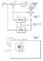
- Figure 1 shows a known form of video coder.
- Video signals (commonly in digital form) are received at an input a.
- a subtractor b forms the difference between the input and a predicted signal from a predictor c, which difference is then further coded in box d.
- the coding performed here is not material to the present invention, but may include thresholding (to suppress transmission of zero or minor differences) quantisation or transform coding, for example.
- the input to the predictor is the sum, formed in an adder e, of the prediction and the coded difference signal decoded in a local decoder f (so that loss of information in the coding and decoding process is included in the predictor loop).
- the differential coding is essentially inter-frame, and the predictor c could simply consist of a one-frame delay; as shown, however, a motion estimator g is also included.
- This compares the frame of the picture being coded with the previous frame being supplied to the predictor. For each block of the current frame (into which the picture is regarded as divided), it identifies that region of the previous frame which the block most closely resembles.
- the vector difference in position between the identified region and the block in question is termed a motion vector (since it usually represents motion of an object within the scene depicted by the television picture) and is applied to the predictor to shift the identified region of the previous frame into the position of the relevant block in the current frame, thereby making the predictor output a better prediction.
- This results in the differences formed by the subtractor b being, on average, smaller, and permits the coder d to encode the picture using a lower bit rate than would otherwise be the case.
- One type of motion estimator works on a block by block basis by comparing each block with the corresponding block of the previous frame and regions positionally shifted from that block position; this involves a considerable amount of processing and often necessitates many accesses to stored versions of both frames.
- the motion estimator to be described regards a "current" frame of a television picture which is being coded as being divided into 8 x 8 blocks - that is, eight picture elements (pixels) horizontally by eight lines vertically.
- a non-interlaced picture is assumed. It is designed to generate for each block a motion vector which indicates the position of the block-sized region, lying within a defined search area of the (or a) previous frame of the picture, which is most similar to the block in question.
- the motion vector is the values of u,v at which the comparison indicates the greatest similarity.
- the test for similarity can be any conventionally used - e.g. the sum of the absolute values of the differences between each of the pixels in the "current" block and the relevant region of the previous frame.
- the search is carried out for each block of the current picture in turn.
- the search area associated with a block may overlap the search areas of a number of other blocks this (see the search area shown dotted in Fig 2 for block N+1) often requires multiple accesses to the previous frame information stored in a frame store, which are time consuming and may interfere with other coder functions.
- the input pixel stream (which is in CIF or other row-scanned format) for the current frame is input into a Current Picture Shuffling Device 1 which converts it into m x n block (for example, 8 x 8 block) format, providing as output, one by one, successive blocks in a row-by-row format; this may be provided as a RAM buffer (operating at pixel rate).
- a Current Picture Array 2 Connected to the output of the Current Picture Shuffler, a Current Picture Array 2, dimensioned to store an m x n block and latch it until the search operation for that block is complete.
- the previous (usually immediately preceding) frame is stored, and is usually available in block format since it will have been encoded in this format; in one type of encoder, as (8 x 8) pixel blocks arranged into (2 x 2) macroblocks (i.e. 16 x 16 pixels) arranged into 11 x 3 Groups of Macroblocks, or GOBs (i.e. 176 x 48 pixels).
- the invention compares each block of the current array with the corresponding block in the previous array, and with pixel-displaced versions of that block. To obtain such pixel-displaced versions, it is therefore necessary to convert the previous picture data out of block format into a pixel format, so that pixel-displaced versions of the block may be obtained. Since it may also be necessary to cross macroblock or GOB boundaries, then in general where such formats are employed, a 4 GOB store will be needed to effect the conversion.
- the pixel format is a column-scanned format.
- a Previous Picture Shuffler 3 which receives as its input the previous frame in block-by-block format and produces as output a column-by-column scanned pixel stream.
- This may be provided using a frame memory configured as a cylindrical RAM store, decoding GOB and block numbers into pixel and line offsets for the write address, and generating the read address using counters to give a column-by-column scan of depth D where D is the search "window" depth.
- m 8
- This output pixel stream is connected as input to a Previous Picture Storage Array 4, which at any instant contains an m x n region with which the block in the corresponding Current Picture Array 2 is to be compared.
- Corresponding cells in the Current Picture Array 2 and Previous Picture Array 4 are connected to form inputs to an arithmetic unit 5 which performs a comparison operation, generating thereby a measure of similarity between the contents of the two arrays.
- Arrays 2 and 4 and Arithmetic Unit 5 will henceforth be termed a 'Processor', P1.
- a Previous Picture Array 4 is conveniently provided as a single, long, FIFO register comprising m (i.e. 8 for an 8x8 block) sections, each section consisting of a FIFO section 5 of predetermined length and a SIPO section 5b of length n-1 with n taps, the sections being connected in series.
- the length of each section is D, the scan depth, so each FIFO section 6a is of length D-n+1; for a ⁇ 7 pixel scan, and 8 x 8 blocks, the FIFO sections 5a are therefore 15 stages in length.
- the pixels appearing at each cell of each SIPO 6b of the Array comprise an m x n window which scans, column-by-column, across the corresponding block held in the Current Picture Array 2, as shown in Figure 5.
- Each block of the Current Picture must be compared with ((2p+1) x (2q+1)) displaced positions, where p and q are respectively the maximum horizontal and vertical search displacements. If the horizontal width p of the search area is greater than m/2, the search areas of neighbouring blocks will overlap, so after the previous picture array 2 has presented all the search positions for one block, it will have passed the first search position of the next. In the prior art, this problem is overcome by repeated access to the previous picture data.
- the problem is sidestepped by allowing the Current Picture Array 2 of the processor P1 to latch every other block of the current picture (blocks N, N+2, N+4, ...) and providing a second processor P2, identical to the first but timed so that its current picture array 2 latches the intervening blocks (N+1, N+3, N+5, ...) (it would alternatively be possible to combine the two processors, to compare 16 x 8 blocks of the Current Picture, in which case the Previous Picture Array would simply comprise two arrays 2 in series). Two processors suffice for searches with p ⁇ m.
- the first pixel to be input to the Previous Picture Input Array 4 from the Previous Picture Shuffler 3 is the pixel at point A.
- column C7 of the Previous Picture Input Array 4 is filled.
- point C is reached, columns C1 to C7 of the Previous Picture Input Array are filled.
- the Current Picture Input Array 2 is filled with Current Picture Pixels of block N to be processed.
- Pixels from point D to point E correspond to search positions (-7,-6), (-7,-5) ... (-7,+7).
- Pixels from point F to point G contain no valid terms for search positions.
- Pixels from point H to point J correspond to search position (-6,-7), (-6,-6) ... (-6,+7) and the whole process continues until point K when all search positions for block N have been covered, i.e. ⁇ 7, ⁇ 7).
- Positions between K and L contain no valid search terms for a ⁇ 7 search.
- Previous Picture Pixels continue to be input to the Previous Picture Input Array 4 of the processor, when at point L the first search position for block N+2 is encountered; at this point, block N+2 is loaded into the current picture array 2.
- this embodiment requires (in the worst case) that the processor make 2 comparisons per pixel clock period and hence, that the Previous Picture Array 4 and the Previous Picture Shuffler 3 clock pixel data through at twice the current input pixel rate, although in general some extra (block overhead) clock periods will also be available.
- the number of processors needed in this embodiment is 2p/m so that a ⁇ 15 search for 8 x 8 blocks requires 4 processors P1-P4, each timed to latch every 4th block in the row.
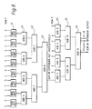
- two rows of blocks are processed at the same time by doubling the number of processors, providing a further two processors P3 and P4 as shown in Figure 6.
- the first FIFO section 6a of processors P4 and P2 are n (e.g. 8) taps shorter than the other FIFO such sections, so that the blocks of pixels within the SIPO sections of P4 and P2 are at any given instant those in the row below the blocks within the SIPO sections of P1 and P3, as shown in Figure 7.
- the Current Picture Arrays 2 of P1 and P3 are arranged (for example, by providing an 8-line delay) to receive blocks from the row above those received by processors P2 and P4.
- this embodiment is functionally equivalent to performing a comparison on 2n x 2m (e.g. 16 x 16) blocks, and it may be convenient to cumulate the similarity measures from the 4 processors to provide a 16 x 16 block output, for example by providing an additional input to each arithmetic unit, linked to the output of another, as shown in Figure 6, and taking the 4-block output from the last processor P1.
- 2n x 2m e.g. 16 x 16
- search areas are possible if more processors are used; for example, a search up to ⁇ 15 pixels requires twice as many processors.
- FIFO sections of controllably variable length, so that the scan depth D can be varied (up to a maximum length).
- Particularly preferred are FIFO sections switchable up to 2q + n stages in length. It is therefore possible to configure a given processor for either a ⁇ 7 search or a ⁇ 15 search by varying the FIFO length.
- the further pair of processors P3, P4 are identical to P1, P2, each Current Picture Array is arranged to latch every 4th block of Current Picture data and the FIFO section of each Previous Picture Array are 15 cells long.
- the FIFO sections of the Previous Picture Arrays are 38 cells long, except for the first sections of P2, P4, P6 and P8 which are 8 cells shorter, and they are connected serially together in order P8, P7, P6, ... P1.
- the Current Picture Arrays P2, P4, P6 and P8 are connected to latch every 4th block of one row and P1, P3, P5 and P7 are connected (e.g. via an 8-line delay) to latch every 4th block of the row below.
- larger horizontal search areas can be realised by using further processors (and larger vertical areas by increasing the FIFO length and the number of processors); preferably, all are identical so as to simplify VLSI fabrication, but certain of the elements within the processors (for example, the previous picture arrays 4) may, if desired, be common to two or more of the processors.
- the measure of similarity calculated by the arithmetic unit is conveniently the Sum Of Absolute Differences (SOAD) between pixels of the Previous and Current Picture Arrays, as disclosed in our previous European published application No. 309251 (incorporated herein by reference).
- SOAD Sum Of Absolute Differences
- Figure 8 A schematic of hardware suitable for VLSI realisation of this function is shown in Figure 8 in which, as shown, an array of m x n subtractors are each connected to one cell of the picture array 4 and of the Current Picture Array 2, and form the absolute, or modulus, difference between the cell contents. Successive cascaded binary adders a1-a6 then accumulate all m x n differences to form E, the sum of Absolute Differences for the block.
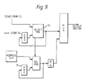
- vectors can be sequentially output and no storage of intermediate results is needed, but associated with each processor is a store 7a for the lowest SOAD calculated, and a comparator 7b for comparing each new SOAD calculated with the stored value and, if the new value is lower, updating the store; a corresponding store 8 for the u and v values defining the search position at which this minimum SOAD occurred is also provided and updated, and when the search for a given block is complete, these stored u and v values form the output motion vector.
- a bias to the zero vector - i.e. a non-zero vector is output only if a region u,v gives a sum of differences E(u,v) which is less by a predetermined amount than the value E (0,0) for the undisplaced region of the previous frame - e.g. is less than 75% of E(0,0).
- This can be achieved by a scaling unit which normally passes the values received from the processor P1 unchanged, but reduces the value to 75% of the input value for position (0,0).
- control logic 9 is necessary to reset the processor after each row of blocks, and to select the search depth and latch or update the Current Picture Array 2, and also because, depending upon the size of the search, there may be a certain number of positions through which the Previous Picture Array 4 passes which fall between the search areas of successive blocks and contain no valid search terms; the control logic "masks" these to prevent the processor from attempting to compare them with the current block.
- One advantage of the present invention is that, in the second embodiment of the invention, a reasonable number of extra clock cycles may be available.
- More processing could, of course, be used if the clock rate of the processors were accelerated over the input pixel rate.
- the advantage of being able to do motion estimation on both luminance and chrominance blocks is that the array processor can be modified to provide the displaced previous picture region (u,v) as well as the displacement vector, or even the prediction error block formed by subtracting the present block from the displaced block.
- the height of the vertical columns in the previous picture input array would have to be increased to compensate for the delay in the arithmetic unit and the motion vector generator.
- There would then be a further block register array whose input is preferably the displaced region from the previous picture input array (but could be the error block if the processor included appropriate subtraction means) and is updated by the motion vector generator. This removes the need to have a separate shuffler external from the chip to output the displaced block for the predictor.
- a border detector (part of control logic 9) serves to ensure that search regions which do not fall wholly within the previous frame are ignored, by masking them (as discussed above) so that the minimum SOAD is not updated for those regions.
Abstract
Description
- The present invention concerns motion estimation, particularly, though not exclusively, in the context of video coders employing inter-frame differential coding.
- Figure 1 shows a known form of video coder. Video signals (commonly in digital form) are received at an input a. A subtractor b forms the difference between the input and a predicted signal from a predictor c, which difference is then further coded in box d. The coding performed here is not material to the present invention, but may include thresholding (to suppress transmission of zero or minor differences) quantisation or transform coding, for example. The input to the predictor is the sum, formed in an adder e, of the prediction and the coded difference signal decoded in a local decoder f (so that loss of information in the coding and decoding process is included in the predictor loop).
- The differential coding is essentially inter-frame, and the predictor c could simply consist of a one-frame delay; as shown, however, a motion estimator g is also included. This compares the frame of the picture being coded with the previous frame being supplied to the predictor. For each block of the current frame (into which the picture is regarded as divided), it identifies that region of the previous frame which the block most closely resembles. The vector difference in position between the identified region and the block in question is termed a motion vector (since it usually represents motion of an object within the scene depicted by the television picture) and is applied to the predictor to shift the identified region of the previous frame into the position of the relevant block in the current frame, thereby making the predictor output a better prediction. This results in the differences formed by the subtractor b being, on average, smaller, and permits the coder d to encode the picture using a lower bit rate than would otherwise be the case.
- One type of motion estimator works on a block by block basis by comparing each block with the corresponding block of the previous frame and regions positionally shifted from that block position; this involves a considerable amount of processing and often necessitates many accesses to stored versions of both frames.
- The present invention is defined in the claims.
- Embodiments of the invention will now be described, with reference to the accompanying drawings, in which:
- - Figure 2 shows a block of the present picture and a corresponding search area of the previous picture;
- - Figure 3 shows schematically a motion vector estimator according to a first embodiment of the invention;
- - Figure 4 shows schematically a Previous Picture Array according to one embodiment of the invention;
- - Figure 5 shows schematically a search scan produced by the invention;
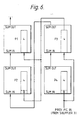
- - Figure 6 shows a second embodiment of the invention;
- - Figure 7 shows schematically the blocks of the present picture processed by the embodiment of Figure 6;
- - Figure 8 shows schematically an arithmetic unit, suitable for calculating a similarity measure as part of the invention; and
- - Figure 9 shows schematically a minimum similarity measure store suitable as part of the invention.
- The motion estimator to be described regards a "current" frame of a television picture which is being coded as being divided into 8 x 8 blocks - that is, eight picture elements (pixels) horizontally by eight lines vertically. Although the principles are equally applicable to interlaced systems, for simplicity of description a non-interlaced picture is assumed. It is designed to generate for each block a motion vector which indicates the position of the block-sized region, lying within a defined search area of the (or a) previous frame of the picture, which is most similar to the block in question.
- Figure 2 illustrates a field with an m x n = 8 x 8 block N (shaded) and an associated 23 x 23 (i.e. 8 + 7 x 2) pixel search area indicated by a rectangle SN. If the pixels horizontally and lines vertically are identified by coordinates x, y, with an origin at the top left-hand corner, then for a block whose upper left hand corner pixel has coordinates xN,yN the search area is the area extending horizontally from (xN-7) to (xN+8+7) and vertically from (yN-7) to (yN+8+7) and contains corresponding n x m rectangular regions with origin co-ordinates from (xN-7, yN-7) to (xN+8, yN+8).
- In order to obtain the motion vector, it is necessary to conduct a search in which the block is compared with each of the (8+7)x(8+7) = 225 possible 8 x 8 regions of the previous frame lying within the search area - i.e. those whose upper left pixel has coordinates xN+u, yN+v where u is in the range ±p and v is in the range ±q. The motion vector is the values of u,v at which the comparison indicates the greatest similarity. The test for similarity can be any conventionally used - e.g. the sum of the absolute values of the differences between each of the pixels in the "current" block and the relevant region of the previous frame.
- Thus, if the current frame and previous frame pixel values are a(i,j) and b(i,j) respectively, then the sum of differences is:-

- Commonly in the prior art, the search is carried out for each block of the current picture in turn. However because the search area associated with a block may overlap the search areas of a number of other blocks this (see the search area shown dotted in Fig 2 for block N+1) often requires multiple accesses to the previous frame information stored in a frame store, which are time consuming and may interfere with other coder functions.
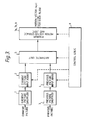
- Referring to Figure 3, the input pixel stream (which is in CIF or other row-scanned format) for the current frame is input into a Current
Picture Shuffling Device 1 which converts it into m x n block (for example, 8 x 8 block) format, providing as output, one by one, successive blocks in a row-by-row format; this may be provided as a RAM buffer (operating at pixel rate). Connected to the output of the Current Picture Shuffler, aCurrent Picture Array 2, dimensioned to store an m x n block and latch it until the search operation for that block is complete. - The previous (usually immediately preceding) frame is stored, and is usually available in block format since it will have been encoded in this format; in one type of encoder, as (8 x 8) pixel blocks arranged into (2 x 2) macroblocks (i.e. 16 x 16 pixels) arranged into 11 x 3 Groups of Macroblocks, or GOBs (i.e. 176 x 48 pixels).
- To estimate a motion vector, the invention compares each block of the current array with the corresponding block in the previous array, and with pixel-displaced versions of that block. To obtain such pixel-displaced versions, it is therefore necessary to convert the previous picture data out of block format into a pixel format, so that pixel-displaced versions of the block may be obtained. Since it may also be necessary to cross macroblock or GOB boundaries, then in general where such formats are employed, a 4 GOB store will be needed to effect the conversion.
- In the invention, the pixel format is a column-scanned format.
- To effect this conversion, a Previous Picture Shuffler 3 is provided which receives as its input the previous frame in block-by-block format and produces as output a column-by-column scanned pixel stream. This may be provided using a frame memory configured as a cylindrical RAM store, decoding GOB and block numbers into pixel and line offsets for the write address, and generating the read address using counters to give a column-by-column scan of depth D where D is the search "window" depth.
- The depth D is determined by the size of the pixel blocks which are being compared in the present and past frames, and by the vertical height over which they are being searched, so that, where m is the block height, and q is the maximum vertical displacement searched, D = m + 2q. For an 8 x 8 pixel block, m = 8, and q may, for example, be ±7, so that in one embodiment, D = 22.
- This output pixel stream is connected as input to a Previous
Picture Storage Array 4, which at any instant contains an m x n region with which the block in the correspondingCurrent Picture Array 2 is to be compared. - Corresponding cells in the
Current Picture Array 2 andPrevious Picture Array 4 are connected to form inputs to anarithmetic unit 5 which performs a comparison operation, generating thereby a measure of similarity between the contents of the two arrays. -
Arrays Arithmetic Unit 5 will henceforth be termed a 'Processor', P1. - Referring to Figure 4, a
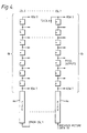
Previous Picture Array 4 is conveniently provided as a single, long, FIFO register comprising m (i.e. 8 for an 8x8 block) sections, each section consisting of aFIFO section 5 of predetermined length and a SIPO section 5b of length n-1 with n taps, the sections being connected in series. The length of each section is D, the scan depth, so each FIFO section 6a is of length D-n+1; for a ±7 pixel scan, and 8 x 8 blocks, the FIFO sections 5a are therefore 15 stages in length. As pixel data is clocked through aPrevious Picture Array 4 in a column-by-column scan, the pixels appearing at each cell of eachSIPO 6b of the Array comprise an m x n window which scans, column-by-column, across the corresponding block held in theCurrent Picture Array 2, as shown in Figure 5. - Each block of the Current Picture must be compared with ((2p+1) x (2q+1)) displaced positions, where p and q are respectively the maximum horizontal and vertical search displacements. If the horizontal width p of the search area is greater than m/2, the search areas of neighbouring blocks will overlap, so after the
previous picture array 2 has presented all the search positions for one block, it will have passed the first search position of the next. In the prior art, this problem is overcome by repeated access to the previous picture data. In one embodiment of the invention, the problem is sidestepped by allowing theCurrent Picture Array 2 of the processor P1 to latch every other block of the current picture (blocks N, N+2, N+4, ...) and providing a second processor P2, identical to the first but timed so that itscurrent picture array 2 latches the intervening blocks (N+1, N+3, N+5, ...) (it would alternatively be possible to combine the two processors, to compare 16 x 8 blocks of the Current Picture, in which case the Previous Picture Array would simply comprise twoarrays 2 in series). Two processors suffice for searches with p<m. - Referring to Figures 4 and 5, the operation of the
Previous Picture Array 4 will now be described. The first pixel to be input to the PreviousPicture Input Array 4 from the Previous Picture Shuffler 3 is the pixel at point A. By the time the pixel at point B is input, column C7 of the PreviousPicture Input Array 4 is filled. when point C is reached, columns C1 to C7 of the Previous Picture Input Array are filled. During the period between point A and point C, the CurrentPicture Input Array 2 is filled with Current Picture Pixels of block N to be processed. - When point D is reached, columns C0 to C7 of the Previous
Picture Input Array 4 are filled and the output taps of theSIPOs 6b contain the pixels for the first valid search position (-7,-7) of block N. - Subsequent pixels that are input from point D to point E correspond to search positions (-7,-6), (-7,-5) ... (-7,+7). Pixels from point F to point G contain no valid terms for search positions. Pixels from point H to point J correspond to search position (-6,-7), (-6,-6) ... (-6,+7) and the whole process continues until point K when all search positions for block N have been covered, i.e. ±7,±7). Positions between K and L contain no valid search terms for a ±7 search.
- Previous Picture Pixels continue to be input to the Previous
Picture Input Array 4 of the processor, when at point L the first search position for block N+2 is encountered; at this point, block N+2 is loaded into thecurrent picture array 2. - Since the Current Picture Array block is latched for 2 x 8 x 8 pixel clock periods only, this embodiment requires (in the worst case) that the processor make 2 comparisons per pixel clock period and hence, that the
Previous Picture Array 4 and the Previous Picture Shuffler 3 clock pixel data through at twice the current input pixel rate, although in general some extra (block overhead) clock periods will also be available. - For larger searches, the number of processors needed in this embodiment is 2p/m so that a ±15 search for 8 x 8 blocks requires 4 processors P1-P4, each timed to latch every 4th block in the row.
- If the vertical search distance q exceeds n/2, then, similarly, the search areas of successive rows of blocks will overlap, and previous frame data will therefore need to be accessed twice (at least) and pass twice (at least) through each processor.
- To avoid this, referring to Figures 6 and 7, in a second embodiment of the invention, two rows of blocks are processed at the same time by doubling the number of processors, providing a further two processors P3 and P4 as shown in Figure 6. In this case, however, the first FIFO section 6a of processors P4 and P2 are n (e.g. 8) taps shorter than the other FIFO such sections, so that the blocks of pixels within the SIPO sections of P4 and P2 are at any given instant those in the row below the blocks within the SIPO sections of P1 and P3, as shown in Figure 7. where two rows of blocks are processed together, the scan depth D needed is (2p + 2m), since the search window is scanned over two current blocks, so the length of the FIFO + SIPO sections, for a ±15 search of two rows of 8 x 8 blocks, is 2q + 2n = 46, and the length of the FIFO is 2q + n = 38. Similarly, the
Current Picture Arrays 2 of P1 and P3 are arranged (for example, by providing an 8-line delay) to receive blocks from the row above those received by processors P2 and P4. - It will be apparent that this embodiment is functionally equivalent to performing a comparison on 2n x 2m (e.g. 16 x 16) blocks, and it may be convenient to cumulate the similarity measures from the 4 processors to provide a 16 x 16 block output, for example by providing an additional input to each arithmetic unit, linked to the output of another, as shown in Figure 6, and taking the 4-block output from the last processor P1.
- This enables selection of different block formats, and is hence of value in providing a general-purpose motion vector integrated circuit.
- Using this second embodiment, a p = m/2 (±7) search requires only a single pass of the previous picture data through the processors, and the processors can run at pixel clock rate (typically, 6.75 MHz).
- In either embodiment, larger search areas are possible if more processors are used; for example, a search up to ±15 pixels requires twice as many processors.
- The preferred form of these embodiments of the invention utilise FIFO sections of controllably variable length, so that the scan depth D can be varied (up to a maximum length). Particularly preferred are FIFO sections switchable up to 2q + n stages in length. It is therefore possible to configure a given processor for either a ±7 search or a ±15 search by varying the FIFO length.
- For the first embodiment, the further pair of processors P3, P4 are identical to P1, P2, each Current Picture Array is arranged to latch every 4th block of Current Picture data and the FIFO section of each Previous Picture Array are 15 cells long.
- For the second embodiment, for a ±15 search, 8 processors P1-P8 are needed, the FIFO sections of the Previous Picture Arrays are 38 cells long, except for the first sections of P2, P4, P6 and P8 which are 8 cells shorter, and they are connected serially together in order P8, P7, P6, ... P1. The Current Picture Arrays P2, P4, P6 and P8 are connected to latch every 4th block of one row and P1, P3, P5 and P7 are connected (e.g. via an 8-line delay) to latch every 4th block of the row below.
- Similarly, larger horizontal search areas can be realised by using further processors (and larger vertical areas by increasing the FIFO length and the number of processors); preferably, all are identical so as to simplify VLSI fabrication, but certain of the elements within the processors (for example, the previous picture arrays 4) may, if desired, be common to two or more of the processors.
- The measure of similarity calculated by the arithmetic unit is conveniently the Sum Of Absolute Differences (SOAD) between pixels of the Previous and Current Picture Arrays, as disclosed in our previous European published application No. 309251 (incorporated herein by reference). A schematic of hardware suitable for VLSI realisation of this function is shown in Figure 8 in which, as shown, an array of m x n subtractors are each connected to one cell of the
picture array 4 and of theCurrent Picture Array 2, and form the absolute, or modulus, difference between the cell contents. Successive cascaded binary adders a1-a6 then accumulate all m x n differences to form E, the sum of Absolute Differences for the block. - Referring to Figure 9, since blocks are sequentially processed, vectors can be sequentially output and no storage of intermediate results is needed, but associated with each processor is a
store 7a for the lowest SOAD calculated, and acomparator 7b for comparing each new SOAD calculated with the stored value and, if the new value is lower, updating the store; acorresponding store 8 for the u and v values defining the search position at which this minimum SOAD occurred is also provided and updated, and when the search for a given block is complete, these stored u and v values form the output motion vector. - Preferably, also, the zero displacement (i.e. u,v = 0) SOAD is stored.
- It may be desired to give a bias to the zero vector - i.e. a non-zero vector is output only if a region u,v gives a sum of differences E(u,v) which is less by a predetermined amount than the value E (0,0) for the undisplaced region of the previous frame - e.g. is less than 75% of E(0,0). This can be achieved by a scaling unit which normally passes the values received from the processor P1 unchanged, but reduces the value to 75% of the input value for position (0,0).
- In general, some
control logic 9 is necessary to reset the processor after each row of blocks, and to select the search depth and latch or update theCurrent Picture Array 2, and also because, depending upon the size of the search, there may be a certain number of positions through which thePrevious Picture Array 4 passes which fall between the search areas of successive blocks and contain no valid search terms; the control logic "masks" these to prevent the processor from attempting to compare them with the current block. - One advantage of the present invention is that, in the second embodiment of the invention, a reasonable number of extra clock cycles may be available.
- For example, in a coder using 8 x 8 blocks arranged in 2 x 2 macroblocks, typically 512 cycles are available per macroblock. A ±15 search of a row of blocks using the second embodiment will take 17572 cycles, of the available 22528, so there are therefore 4956 spare cycles per row.
- In a colour video signal, this is sufficient time to process also the chrominance blocks U and V corresponding to a given luminance block, either because such data is usually subsampled or by using a smaller (±7) search window which will require only 4180 cycles.
- More processing could, of course, be used if the clock rate of the processors were accelerated over the input pixel rate.
- The advantage of being able to do motion estimation on both luminance and chrominance blocks is that the array processor can be modified to provide the displaced previous picture region (u,v) as well as the displacement vector, or even the prediction error block formed by subtracting the present block from the displaced block. The height of the vertical columns in the previous picture input array would have to be increased to compensate for the delay in the arithmetic unit and the motion vector generator. There would then be a further block register array whose input is preferably the displaced region from the previous picture input array (but could be the error block if the processor included appropriate subtraction means) and is updated by the motion vector generator. This removes the need to have a separate shuffler external from the chip to output the displaced block for the predictor.
- The description so far has conveniently ignored problems that may arise where the block under consideration is within 8 lines or pixels of the edge of the picture - i.e. certain of the regions defined by x, y, u, v overlap the line and field blanking periods. This is readily overcome by disregarding such regions. A border detector (part of control logic 9) serves to ensure that search regions which do not fall wholly within the previous frame are ignored, by masking them (as discussed above) so that the minimum SOAD is not updated for those regions.
- Although the invention thus far described has operated upon blocks sequentially along a row, with a column-by-column scan, by providing different current and
past picture shufflers
Claims (14)
- means for reception and temporary storage of signals representing one line-scanned frame of a picture and of signals representing another such frame of the picture; and
- means for comparing each of a plurality of blocks into which the said one frame is divided with the corresponding region of the other frame and with a plurality of positionally shifted regions of the other frame, to produce vector information indicating the positional shift if any between the position of the block and the position of that region of the other frame which meets a criterion of similarity between the block and the regions,
characterised in that the comparison means is arranged to operate sequentially upon blocks disposed in rows aligned with the picture line direction of said one frame, and to compare each with the said plurality of positionally shifted regions of the other frame in a sequential column-by-column scan of part of said other frame.
(i) first picture storage means for simultaneously making available, for a period corresponding to a desired search extent in the line direction of the picture, a group of picture elements corresponding to a block of the said one frame, where successive groups within a sequence of such groups correspond to respective non-overlapping blocks; and
(ii) second picture storage means for making simultaneously available a group of picture elements corresponding to a region of the other frame of the same size as the block, where successive groups within a sequence of such groups correspond to regions progressively shifted in a direction down in a column of the lines of the picture, and successive such sequences correspond to regions progressively shifted along the lines;
and the comparing means comprise arithmetic means for forming the sum of the moduli or other monotonically increasing even function of the differences between the elements made available for a block and the elements made available for a region and means to ascertain for each block the vector information corresponding to the region whose sum meets the said criterion.
- there are provided A arithmetic means;
- each is connected to a first delay and storage means such that each processes blocks of a different row of said one frame;
- each is connected to a second delay means which includes one FIFO stage of such a length that the regions of said other frame which each arithmetic means at a given time is comparing are vertically displaced one from another by n rows; and
- the lengths of the other FIFO stages of such second delay means are 2q + (A-1) n.
(i) first picture storage means for simultaneously making available, for a period corresponding to a desired search extent in the line direction of the picture, a group of picture elements corresponding to a block of the said one frame, where successive groups within a sequence of such groups correspond to respective non-overlapping blocks; and
(ii) second picture storage means for making simultaneously available a group of picture elements corresponding to a region of the other frame of the same size as the block, where successive groups within a sequence of such groups correspond to regions progressively shifted in a direction down in a column of the lines of the picture, and successive such sequences correspond to regions progressively shifted along the lines; and
(iii) arithmetic means for forming the sum of the moduli or other monotonically increasing even function of the differences between the elements made available for a block and the elements made available for a region and means to ascertain for each block the vector information corresponding to the region whose sum meets the said criterion;
in which:
the first and second picture storage means of some of the processors are configurable, so as to process blocks in vertically neighbouring rows simultaneously, and the arithmetic means of the processors are connectable and means are provided for forming the sum of the said sums of difference function for each processor, whereby the motion detector may be configured to compare composite blocks comprising a plurality of neighbouring said blocks.
- means for reception and temporary storage of signals representing one line-scanned frame of a picture and of signals representing another such frame of the picture; and
- means for comparing each of a plurality of blocks into which the said one frame is divided with the corresponding region of the other frame and with a plurality of positionally shifted regions of the other frame, to produce vector information indicating the positional shift if any between the position of the block and the position of that region of the other frame which meets a criterion of similarity between the block and the regions,
characterised in that the comparison means is arranged to operate sequentially upon blocks disposed in columns aligned normal to the picture line direction of said one frame, and to compare each with the said plurality of positionally shifted regions of the other frame in a sequential row-by-row scan of part of said other frame.
Applications Claiming Priority (2)
| Application Number | Priority Date | Filing Date | Title |
|---|---|---|---|
| GB898909498A GB8909498D0 (en) | 1989-04-26 | 1989-04-26 | Motion estimator |
| GB8909498 | 1989-04-26 |
Publications (2)
| Publication Number | Publication Date |
|---|---|
| EP0395293A1 true EP0395293A1 (en) | 1990-10-31 |
| EP0395293B1 EP0395293B1 (en) | 1998-06-24 |
Family
ID=10655732
Family Applications (1)
| Application Number | Title | Priority Date | Filing Date |
|---|---|---|---|
| EP90304166A Expired - Lifetime EP0395293B1 (en) | 1989-04-26 | 1990-04-18 | Motion estimator |
Country Status (15)
| Country | Link |
|---|---|
| US (1) | US5206723A (en) |
| EP (1) | EP0395293B1 (en) |
| JP (1) | JP2839950B2 (en) |
| KR (1) | KR100203913B1 (en) |
| AT (1) | ATE167773T1 (en) |
| AU (1) | AU626120B2 (en) |
| CA (1) | CA2053241C (en) |
| DD (1) | DD293933A5 (en) |
| DE (1) | DE69032437T2 (en) |
| DK (1) | DK0395293T3 (en) |
| ES (1) | ES2118713T3 (en) |
| GB (1) | GB8909498D0 (en) |
| HK (1) | HK1014434A1 (en) |
| SG (1) | SG43206A1 (en) |
| WO (1) | WO1990013205A1 (en) |
Cited By (25)
| Publication number | Priority date | Publication date | Assignee | Title |
|---|---|---|---|---|
| EP0488795A2 (en) * | 1990-11-30 | 1992-06-03 | Sony Corporation | Motion vector detection and band compression apparatus |
| FR2693290A1 (en) * | 1992-07-06 | 1994-01-07 | Mitsubishi Electric Corp | Motion vector detection device for motion compensation in a moving image. |
| EP0615206A1 (en) * | 1993-03-11 | 1994-09-14 | Integrated Information Technology, Inc., | Programmable architecture and methods for motion estimation |
| WO1995004433A1 (en) * | 1993-07-30 | 1995-02-09 | British Telecommunications Public Limited Company | Processing image data |
| WO1995009404A1 (en) * | 1993-09-30 | 1995-04-06 | Siemens Aktiengesellschaft | Processor for comparing blocks of picture elements (block matching processor) |
| US5430886A (en) * | 1992-06-15 | 1995-07-04 | Furtek; Frederick C. | Method and apparatus for motion estimation |
| EP0680013A2 (en) * | 1994-04-29 | 1995-11-02 | Sun Microsystems, Inc. | Central processing unit with integrated graphics functions |
| EP0680220A1 (en) * | 1994-04-27 | 1995-11-02 | STMicroelectronics S.A. | Apparatus and method for addressing a cache-memory of a moving picture compression circuit |
| FR2723796A1 (en) * | 1994-08-19 | 1996-02-23 | Thomson Consumer Electronics | MOTION ESTIMATING DEVICE |
| US5594813A (en) * | 1992-02-19 | 1997-01-14 | Integrated Information Technology, Inc. | Programmable architecture and methods for motion estimation |
| AU674984B2 (en) * | 1993-07-30 | 1997-01-16 | British Telecommunications Public Limited Company | Processing image data |
| WO1997013372A2 (en) * | 1995-10-05 | 1997-04-10 | Microsoft Corporation | Feature-based video compression method |
| US5748789A (en) * | 1996-10-31 | 1998-05-05 | Microsoft Corporation | Transparent block skipping in object-based video coding systems |
| US5764814A (en) * | 1996-03-22 | 1998-06-09 | Microsoft Corporation | Representation and encoding of general arbitrary shapes |
| US5778098A (en) * | 1996-03-22 | 1998-07-07 | Microsoft Corporation | Sprite coding |
| US5787203A (en) * | 1996-01-19 | 1998-07-28 | Microsoft Corporation | Method and system for filtering compressed video images |
| US5790712A (en) * | 1992-02-19 | 1998-08-04 | 8×8, Inc. | Video compression/decompression processing and processors |
| US5799113A (en) * | 1996-01-19 | 1998-08-25 | Microsoft Corporation | Method for expanding contracted video images |
| US5859631A (en) * | 1995-12-21 | 1999-01-12 | Siemens Elema Ab | Apparatus front panel allowing indicia on an indicia-bearing element to be read therethrough |
| EP0941608A1 (en) * | 1996-12-03 | 1999-09-15 | Zapex Technologies (Israel) Ltd. | Apparatus for and method of reducing the memory bandwidth requirements of a systolic array |
| US5982438A (en) * | 1996-03-22 | 1999-11-09 | Microsoft Corporation | Overlapped motion compensation for object coding |
| US6075875A (en) * | 1996-09-30 | 2000-06-13 | Microsoft Corporation | Segmentation of image features using hierarchical analysis of multi-valued image data and weighted averaging of segmentation results |
| US6400831B2 (en) | 1998-04-02 | 2002-06-04 | Microsoft Corporation | Semantic video object segmentation and tracking |
| WO2003049034A2 (en) * | 2001-12-03 | 2003-06-12 | Koninklijke Philips Electronics N.V. | Image data retrieval |
| EP1370086A1 (en) * | 2002-06-07 | 2003-12-10 | STMicroelectronics S.r.l. | Programmable system for motion vector generation |
Families Citing this family (28)
| Publication number | Priority date | Publication date | Assignee | Title |
|---|---|---|---|---|
| JP2569219B2 (en) * | 1990-01-31 | 1997-01-08 | 富士通株式会社 | Video prediction method |
| JP3004697B2 (en) * | 1990-08-27 | 2000-01-31 | 沖電気工業株式会社 | Motion vector detection circuit |
| US5138447A (en) * | 1991-02-11 | 1992-08-11 | General Instrument Corporation | Method and apparatus for communicating compressed digital video signals using multiple processors |
| EP0520765B1 (en) * | 1991-06-25 | 1999-05-12 | Canon Kabushiki Kaisha | Movement vector detecting method/apparatus and encoding method/apparatus using such method/apparatus |
| KR0160618B1 (en) * | 1992-10-27 | 1999-01-15 | 윤종용 | Device and method for real time moving estimation |
| US5485214A (en) * | 1993-02-25 | 1996-01-16 | Industrial Technology Research Institute | Dual bus dual bank architecture for motion compensation |
| JP3163837B2 (en) * | 1993-04-16 | 2001-05-08 | ソニー株式会社 | Digital video signal encoding device |
| KR950014343B1 (en) * | 1993-05-20 | 1995-11-24 | 한국방송공사 | Method of and apparatus for motion estimation of video data |
| US5793428A (en) * | 1993-06-16 | 1998-08-11 | Intel Corporation | Self-encoded deltas for digital video data transmission |
| US5477272A (en) * | 1993-07-22 | 1995-12-19 | Gte Laboratories Incorporated | Variable-block size multi-resolution motion estimation scheme for pyramid coding |
| US5396284A (en) * | 1993-08-20 | 1995-03-07 | Burle Technologies, Inc. | Motion detection system |
| US5495292A (en) * | 1993-09-03 | 1996-02-27 | Gte Laboratories Incorporated | Inter-frame wavelet transform coder for color video compression |
| US5929913A (en) * | 1993-10-28 | 1999-07-27 | Matsushita Electrical Industrial Co., Ltd | Motion vector detector and video coder |
| DE4344924A1 (en) * | 1993-12-30 | 1995-08-10 | Thomson Brandt Gmbh | Method and device for motion estimation |
| US5563813A (en) * | 1994-06-01 | 1996-10-08 | Industrial Technology Research Institute | Area/time-efficient motion estimation micro core |
| KR100349883B1 (en) * | 1994-07-27 | 2002-12-16 | 소니 가부시끼 가이샤 | Method and apparatus for motion vector detection and image signal encoding |
| US5668609A (en) * | 1994-09-08 | 1997-09-16 | Tektronix, Inc. | Motion detector and key signal interpolator using same |
| US5627601A (en) * | 1994-11-30 | 1997-05-06 | National Semiconductor Corporation | Motion estimation with bit rate criterion |
| US5644361A (en) * | 1994-11-30 | 1997-07-01 | National Semiconductor Corporation | Subsampled frame storage technique for reduced memory size |
| GB2301971B (en) * | 1995-06-06 | 1999-10-06 | Sony Uk Ltd | Video compression |
| KR100202565B1 (en) * | 1996-03-23 | 1999-06-15 | 구자홍 | The stereoscopic brightness/chrominance separating apparatus of composite image signal |
| JPH1091795A (en) * | 1996-09-12 | 1998-04-10 | Toshiba Corp | Device for detecting mobile object and method therefor |
| US5984514A (en) * | 1996-12-20 | 1999-11-16 | Analog Devices, Inc. | Method and apparatus for using minimal and optimal amount of SRAM delay line storage in the calculation of an X Y separable mallat wavelet transform |
| US5838377A (en) * | 1996-12-20 | 1998-11-17 | Analog Devices, Inc. | Video compressed circuit using recursive wavelet filtering |
| ES2138545B1 (en) * | 1997-11-04 | 2000-08-16 | Univ Castilla La Mancha | COMPUTER SYSTEM FOR PERFORMING SPACE-TEMPORARY ACCUMULATION OF ACTIVATION IN DIGITAL SIGNALS. |
| KR100457065B1 (en) * | 1998-12-29 | 2005-05-19 | 주식회사 대우일렉트로닉스 | Motion vector generator for video signals |
| FR2906054B1 (en) * | 2006-09-19 | 2009-02-27 | Thales Sa | METHOD FOR RECORDING A GRAPHIC DATA STREAM, IN PARTICULAR FOR COMPUTER APLLICATIONS |
| WO2019000443A1 (en) * | 2017-06-30 | 2019-01-03 | 华为技术有限公司 | Inter-frame prediction method and device |
Citations (3)
| Publication number | Priority date | Publication date | Assignee | Title |
|---|---|---|---|---|
| WO1982001454A1 (en) * | 1980-10-22 | 1982-04-29 | Mahoney Trevor W | Video movement detector |
| EP0241983A1 (en) * | 1986-04-15 | 1987-10-21 | Laboratoires D'electronique Philips | Image-processing device for estimating the displacement of objects within the image |
| EP0309251B1 (en) * | 1987-09-25 | 1993-11-18 | BRITISH TELECOMMUNICATIONS public limited company | Motion estimator |
Family Cites Families (3)
| Publication number | Priority date | Publication date | Assignee | Title |
|---|---|---|---|---|
| JPS5752281A (en) * | 1980-09-12 | 1982-03-27 | Nec Corp | Forecast encoding device of picture signal |
| JPS63244985A (en) * | 1987-03-30 | 1988-10-12 | Mitsubishi Electric Corp | Movement compensating inter-frame encoder |
| DE3811535A1 (en) * | 1988-04-06 | 1989-10-19 | Philips Patentverwaltung | HYBRID CODERS FOR VIDEO SIGNALS |
-
1989
- 1989-04-26 GB GB898909498A patent/GB8909498D0/en active Pending
-
1990
- 1990-04-18 DE DE69032437T patent/DE69032437T2/en not_active Expired - Fee Related
- 1990-04-18 ES ES90304166T patent/ES2118713T3/en not_active Expired - Lifetime
- 1990-04-18 JP JP2506027A patent/JP2839950B2/en not_active Expired - Fee Related
- 1990-04-18 KR KR1019910701472A patent/KR100203913B1/en not_active IP Right Cessation
- 1990-04-18 AT AT90304166T patent/ATE167773T1/en active
- 1990-04-18 US US07/778,802 patent/US5206723A/en not_active Expired - Lifetime
- 1990-04-18 DK DK90304166T patent/DK0395293T3/en active
- 1990-04-18 EP EP90304166A patent/EP0395293B1/en not_active Expired - Lifetime
- 1990-04-18 SG SG1996005514A patent/SG43206A1/en unknown
- 1990-04-18 AU AU54223/90A patent/AU626120B2/en not_active Ceased
- 1990-04-18 WO PCT/GB1990/000581 patent/WO1990013205A1/en active Application Filing
- 1990-04-18 CA CA002053241A patent/CA2053241C/en not_active Expired - Lifetime
- 1990-04-25 DD DD90340098A patent/DD293933A5/en not_active IP Right Cessation
-
1998
- 1998-12-24 HK HK98115735A patent/HK1014434A1/en not_active IP Right Cessation
Patent Citations (3)
| Publication number | Priority date | Publication date | Assignee | Title |
|---|---|---|---|---|
| WO1982001454A1 (en) * | 1980-10-22 | 1982-04-29 | Mahoney Trevor W | Video movement detector |
| EP0241983A1 (en) * | 1986-04-15 | 1987-10-21 | Laboratoires D'electronique Philips | Image-processing device for estimating the displacement of objects within the image |
| EP0309251B1 (en) * | 1987-09-25 | 1993-11-18 | BRITISH TELECOMMUNICATIONS public limited company | Motion estimator |
Non-Patent Citations (2)
| Title |
|---|
| IEEE/IEICE GLOBECOM CONFERENCE '87, Tokyo, 15th - 18th November 1987, vol. 1, pages 2.6.1 - 2.6.4, IEEE, New York, US; T.R. HSING: "Motion detection and compensation coding for motion video coders: Technical review and comparison" * |
| PROCEEDINGS OF THE INTERNATIONAL CONFERENCE ON ACOUSTICS, SPEECH, AND SIGNAL PROCESSING, Dallas, Texas, 6th - 9th April 1987, vol. 2, pages 25.4.1 - 25.4.4, IEEE, New York, US; A. PURI et al.: "An efficient block-matching algorithm for motion-compensated coding" * |
Cited By (51)
| Publication number | Priority date | Publication date | Assignee | Title |
|---|---|---|---|---|
| EP0488795A3 (en) * | 1990-11-30 | 1994-02-23 | Sony Corp | |
| EP0488795A2 (en) * | 1990-11-30 | 1992-06-03 | Sony Corporation | Motion vector detection and band compression apparatus |
| US5790712A (en) * | 1992-02-19 | 1998-08-04 | 8×8, Inc. | Video compression/decompression processing and processors |
| US5594813A (en) * | 1992-02-19 | 1997-01-14 | Integrated Information Technology, Inc. | Programmable architecture and methods for motion estimation |
| US5504931A (en) * | 1992-06-15 | 1996-04-02 | Atmel Corporation | Method and apparatus for comparing data sets |
| US5430886A (en) * | 1992-06-15 | 1995-07-04 | Furtek; Frederick C. | Method and apparatus for motion estimation |
| FR2693290A1 (en) * | 1992-07-06 | 1994-01-07 | Mitsubishi Electric Corp | Motion vector detection device for motion compensation in a moving image. |
| DE4322343A1 (en) * | 1992-07-06 | 1994-01-13 | Mitsubishi Electric Corp | Movement vector detector for compensating movement in image - uses reference window data and comparator receiving summed outputs of processor elements to derive movement vector for pattern block of current image |
| US5400087A (en) * | 1992-07-06 | 1995-03-21 | Mitsubishi Denki Kabushiki Kaisha | Motion vector detecting device for compensating for movements in a motion picture |
| EP0615206A1 (en) * | 1993-03-11 | 1994-09-14 | Integrated Information Technology, Inc., | Programmable architecture and methods for motion estimation |
| WO1995004433A1 (en) * | 1993-07-30 | 1995-02-09 | British Telecommunications Public Limited Company | Processing image data |
| AU674984B2 (en) * | 1993-07-30 | 1997-01-16 | British Telecommunications Public Limited Company | Processing image data |
| US5805239A (en) * | 1993-09-30 | 1998-09-08 | Siemens Aktiengesellschaft | Processor for comparing picture element blocks (blocks matching processor) |
| WO1995009404A1 (en) * | 1993-09-30 | 1995-04-06 | Siemens Aktiengesellschaft | Processor for comparing blocks of picture elements (block matching processor) |
| EP0680220A1 (en) * | 1994-04-27 | 1995-11-02 | STMicroelectronics S.A. | Apparatus and method for addressing a cache-memory of a moving picture compression circuit |
| FR2719398A1 (en) * | 1994-04-27 | 1995-11-03 | Sgs Thomson Microelectronics | Device and method for addressing a cache memory of a mobile image compression circuit. |
| CN1072883C (en) * | 1994-04-27 | 2001-10-10 | Sgs-汤姆森微电子公司 | A device for addressing a cache memory of a compressing motion picture circuit |
| US5938756A (en) * | 1994-04-29 | 1999-08-17 | Sun Microsystems, Inc. | Central processing unit with integrated graphics functions |
| EP0680013A3 (en) * | 1994-04-29 | 1997-04-02 | Sun Microsystems Inc | Central processing unit with integrated graphics functions. |
| US5933157A (en) * | 1994-04-29 | 1999-08-03 | Sun Microsystems, Inc. | Central processing unit with integrated graphics functions |
| EP0680013A2 (en) * | 1994-04-29 | 1995-11-02 | Sun Microsystems, Inc. | Central processing unit with integrated graphics functions |
| US5745605A (en) * | 1994-08-19 | 1998-04-28 | Deutsche Thomson Brandt Gmbh | Device for estimation of movement |
| EP0702327A1 (en) * | 1994-08-19 | 1996-03-20 | THOMSON multimedia | Movement estimation device |
| FR2723796A1 (en) * | 1994-08-19 | 1996-02-23 | Thomson Consumer Electronics | MOTION ESTIMATING DEVICE |
| WO1997013372A2 (en) * | 1995-10-05 | 1997-04-10 | Microsoft Corporation | Feature-based video compression method |
| US5784175A (en) * | 1995-10-05 | 1998-07-21 | Microsoft Corporation | Pixel block correlation process |
| US5995670A (en) * | 1995-10-05 | 1999-11-30 | Microsoft Corporation | Simplified chain encoding |
| US5796855A (en) * | 1995-10-05 | 1998-08-18 | Microsoft Corporation | Polygon block matching method |
| US5970173A (en) * | 1995-10-05 | 1999-10-19 | Microsoft Corporation | Image compression and affine transformation for image motion compensation |
| US6026182A (en) * | 1995-10-05 | 2000-02-15 | Microsoft Corporation | Feature segmentation |
| US5825929A (en) * | 1995-10-05 | 1998-10-20 | Microsoft Corporation | Transformation block optimization method |
| WO1997013372A3 (en) * | 1995-10-05 | 1997-05-29 | Microsoft Corp | Feature-based video compression method |
| US5933535A (en) * | 1995-10-05 | 1999-08-03 | Microsoft Corporation | Object-based video compression process employing arbitrarily-shaped features |
| US5949919A (en) * | 1995-10-05 | 1999-09-07 | Microsoft Corporation | Precompression extrapolation method |
| US5959673A (en) * | 1995-10-05 | 1999-09-28 | Microsoft Corporation | Transform coding of dense motion vector fields for frame and object based video coding applications |
| US5859631A (en) * | 1995-12-21 | 1999-01-12 | Siemens Elema Ab | Apparatus front panel allowing indicia on an indicia-bearing element to be read therethrough |
| US5787203A (en) * | 1996-01-19 | 1998-07-28 | Microsoft Corporation | Method and system for filtering compressed video images |
| US5799113A (en) * | 1996-01-19 | 1998-08-25 | Microsoft Corporation | Method for expanding contracted video images |
| US5764814A (en) * | 1996-03-22 | 1998-06-09 | Microsoft Corporation | Representation and encoding of general arbitrary shapes |
| US5946419A (en) * | 1996-03-22 | 1999-08-31 | Microsoft Corporation | Separate shape and texture coding of transparency data for video coding applications |
| US5982438A (en) * | 1996-03-22 | 1999-11-09 | Microsoft Corporation | Overlapped motion compensation for object coding |
| US5778098A (en) * | 1996-03-22 | 1998-07-07 | Microsoft Corporation | Sprite coding |
| US6075875A (en) * | 1996-09-30 | 2000-06-13 | Microsoft Corporation | Segmentation of image features using hierarchical analysis of multi-valued image data and weighted averaging of segmentation results |
| US5748789A (en) * | 1996-10-31 | 1998-05-05 | Microsoft Corporation | Transparent block skipping in object-based video coding systems |
| EP0941608A1 (en) * | 1996-12-03 | 1999-09-15 | Zapex Technologies (Israel) Ltd. | Apparatus for and method of reducing the memory bandwidth requirements of a systolic array |
| EP0941608A4 (en) * | 1996-12-03 | 2001-08-29 | Zapex Technologies Inc | Apparatus for and method of reducing the memory bandwidth requirements of a systolic array |
| US6400831B2 (en) | 1998-04-02 | 2002-06-04 | Microsoft Corporation | Semantic video object segmentation and tracking |
| WO2003049034A2 (en) * | 2001-12-03 | 2003-06-12 | Koninklijke Philips Electronics N.V. | Image data retrieval |
| WO2003049034A3 (en) * | 2001-12-03 | 2003-11-20 | Koninkl Philips Electronics Nv | Image data retrieval |
| EP1370086A1 (en) * | 2002-06-07 | 2003-12-10 | STMicroelectronics S.r.l. | Programmable system for motion vector generation |
| US7272184B2 (en) | 2002-06-07 | 2007-09-18 | Stmicroelectronics S.R.L. | Programmable system for motion vector generation |
Also Published As
| Publication number | Publication date |
|---|---|
| KR920702156A (en) | 1992-08-12 |
| DE69032437T2 (en) | 1998-12-10 |
| ES2118713T3 (en) | 1998-10-01 |
| GB8909498D0 (en) | 1989-06-14 |
| CA2053241A1 (en) | 1990-10-27 |
| KR100203913B1 (en) | 1999-06-15 |
| AU5422390A (en) | 1990-11-16 |
| JP2839950B2 (en) | 1998-12-24 |
| US5206723A (en) | 1993-04-27 |
| EP0395293B1 (en) | 1998-06-24 |
| DE69032437D1 (en) | 1998-07-30 |
| DK0395293T3 (en) | 1999-04-06 |
| CA2053241C (en) | 1998-11-10 |
| AU626120B2 (en) | 1992-07-23 |
| ATE167773T1 (en) | 1998-07-15 |
| JPH04506889A (en) | 1992-11-26 |
| DD293933A5 (en) | 1991-09-12 |
| WO1990013205A1 (en) | 1990-11-01 |
| SG43206A1 (en) | 1997-10-17 |
| HK1014434A1 (en) | 1999-09-24 |
Similar Documents
| Publication | Publication Date | Title |
|---|---|---|
| AU626120B2 (en) | Motion estimator | |
| US5083202A (en) | Motion detector for video signals including a novel line comparison processing scheme | |
| EP0528293B1 (en) | Apparatus for reducing quantization artifacts in an interframe hybrid coding system with motion compensation | |
| US5210605A (en) | Method and apparatus for determining motion vectors for image sequences | |
| US5557341A (en) | Iterative method for estimating motion content in video signals using successively reduced block size | |
| US5398068A (en) | Method and apparatus for determining motion vectors for image sequences | |
| US5226093A (en) | Motion vector detection and band compression apparatus | |
| US6295381B1 (en) | Coding apparatus and decoding apparatus of image data and corresponding shape data at different resolutions | |
| JP3436367B2 (en) | Digital video signal processor device | |
| EP0944245B1 (en) | Hierarchical recursive motion estimator for video images encoder | |
| WO1999066733A2 (en) | Pixel data storage system for use in half-pel interpolation | |
| EP0920204B1 (en) | MPEG-2 decoder with reduced RAM requisite by recompression using adaptive tree search vector quantization | |
| US5010402A (en) | Video signal compression apparatus | |
| US20030103567A1 (en) | Motion compensation and/or estimation | |
| IE901502A1 (en) | Motion estimator | |
| JP3191753B2 (en) | Image encoding device, image decoding device, image encoding method, image decoding method | |
| EP1094671A1 (en) | Method of motion estimation for a digital input video signal | |
| EP0474272B1 (en) | Method and apparatus for reducing motion estimator hardware and data transmission capacity requirements in video systems | |
| EP1094669A1 (en) | Method of motion estimation for a digital input video signal | |
| JP3004686B2 (en) | Encoding circuit and image encoding device | |
| JP2983170B2 (en) | Motion vector search method and search device | |
| JPH0993587A (en) | Motion vector retrieval method and retrieval device | |
| JPH0388590A (en) | Encoder for television signal | |
| JPH0265373A (en) | Encoding system for picture |
Legal Events
| Date | Code | Title | Description |
|---|---|---|---|
| PUAI | Public reference made under article 153(3) epc to a published international application that has entered the european phase |
Free format text: ORIGINAL CODE: 0009012 |
|
| AK | Designated contracting states |
Kind code of ref document: A1 Designated state(s): AT BE CH DE DK ES FR GB GR IT LI LU NL SE |
|
| 17P | Request for examination filed |
Effective date: 19910411 |
|
| 17Q | First examination report despatched |
Effective date: 19930312 |
|
| GRAG | Despatch of communication of intention to grant |
Free format text: ORIGINAL CODE: EPIDOS AGRA |
|
| GRAG | Despatch of communication of intention to grant |
Free format text: ORIGINAL CODE: EPIDOS AGRA |
|
| GRAG | Despatch of communication of intention to grant |
Free format text: ORIGINAL CODE: EPIDOS AGRA |
|
| GRAH | Despatch of communication of intention to grant a patent |
Free format text: ORIGINAL CODE: EPIDOS IGRA |
|
| GRAH | Despatch of communication of intention to grant a patent |
Free format text: ORIGINAL CODE: EPIDOS IGRA |
|
| GRAA | (expected) grant |
Free format text: ORIGINAL CODE: 0009210 |
|
| AK | Designated contracting states |
Kind code of ref document: B1 Designated state(s): AT BE CH DE DK ES FR GB GR IT LI LU NL SE |
|
| PG25 | Lapsed in a contracting state [announced via postgrant information from national office to epo] |
Ref country code: GR Free format text: LAPSE BECAUSE OF NON-PAYMENT OF DUE FEES Effective date: 19980624 Ref country code: AT Free format text: LAPSE BECAUSE OF FAILURE TO SUBMIT A TRANSLATION OF THE DESCRIPTION OR TO PAY THE FEE WITHIN THE PRESCRIBED TIME-LIMIT Effective date: 19980624 |
|
| REF | Corresponds to: |
Ref document number: 167773 Country of ref document: AT Date of ref document: 19980715 Kind code of ref document: T |
|
| ITF | It: translation for a ep patent filed |
Owner name: JACOBACCI & PERANI S.P.A. |
|
| REG | Reference to a national code |
Ref country code: CH Ref legal event code: EP |
|
| REF | Corresponds to: |
Ref document number: 69032437 Country of ref document: DE Date of ref document: 19980730 |
|
| REG | Reference to a national code |
Ref country code: CH Ref legal event code: NV Representative=s name: JACOBACCI & PERANI S.A. |
|
| REG | Reference to a national code |
Ref country code: ES Ref legal event code: FG2A Ref document number: 2118713 Country of ref document: ES Kind code of ref document: T3 |
|
| ET | Fr: translation filed | ||
| REG | Reference to a national code |
Ref country code: DK Ref legal event code: T3 |
|
| PG25 | Lapsed in a contracting state [announced via postgrant information from national office to epo] |
Ref country code: LU Free format text: LAPSE BECAUSE OF NON-PAYMENT OF DUE FEES Effective date: 19990418 |
|
| PG25 | Lapsed in a contracting state [announced via postgrant information from national office to epo] |
Ref country code: ES Free format text: LAPSE BECAUSE OF NON-PAYMENT OF DUE FEES Effective date: 19990419 |
|
| PG25 | Lapsed in a contracting state [announced via postgrant information from national office to epo] |
Ref country code: DK Free format text: LAPSE BECAUSE OF NON-PAYMENT OF DUE FEES Effective date: 19990430 Ref country code: BE Free format text: LAPSE BECAUSE OF NON-PAYMENT OF DUE FEES Effective date: 19990430 Ref country code: LI Free format text: LAPSE BECAUSE OF NON-PAYMENT OF DUE FEES Effective date: 19990430 Ref country code: CH Free format text: LAPSE BECAUSE OF NON-PAYMENT OF DUE FEES Effective date: 19990430 |
|
| PLBE | No opposition filed within time limit |
Free format text: ORIGINAL CODE: 0009261 |
|
| STAA | Information on the status of an ep patent application or granted ep patent |
Free format text: STATUS: NO OPPOSITION FILED WITHIN TIME LIMIT |
|
| 26N | No opposition filed | ||
| BERE | Be: lapsed |
Owner name: BRITISH TELECOMMUNICATIONS P.L.C. Effective date: 19990430 |
|
| REG | Reference to a national code |
Ref country code: CH Ref legal event code: PL |
|
| REG | Reference to a national code |
Ref country code: DK Ref legal event code: EBP |
|
| REG | Reference to a national code |
Ref country code: GB Ref legal event code: IF02 |
|
| PGFP | Annual fee paid to national office [announced via postgrant information from national office to epo] |
Ref country code: NL Payment date: 20020318 Year of fee payment: 13 |
|
| PGFP | Annual fee paid to national office [announced via postgrant information from national office to epo] |
Ref country code: SE Payment date: 20020319 Year of fee payment: 13 |
|
| REG | Reference to a national code |
Ref country code: ES Ref legal event code: FD2A Effective date: 20030203 |
|
| PG25 | Lapsed in a contracting state [announced via postgrant information from national office to epo] |
Ref country code: SE Free format text: LAPSE BECAUSE OF NON-PAYMENT OF DUE FEES Effective date: 20030419 |
|
| PG25 | Lapsed in a contracting state [announced via postgrant information from national office to epo] |
Ref country code: NL Free format text: LAPSE BECAUSE OF NON-PAYMENT OF DUE FEES Effective date: 20031101 |
|
| NLV4 | Nl: lapsed or anulled due to non-payment of the annual fee |
Effective date: 20031101 |
|
| EUG | Se: european patent has lapsed | ||
| PG25 | Lapsed in a contracting state [announced via postgrant information from national office to epo] |
Ref country code: IT Free format text: LAPSE BECAUSE OF NON-PAYMENT OF DUE FEES;WARNING: LAPSES OF ITALIAN PATENTS WITH EFFECTIVE DATE BEFORE 2007 MAY HAVE OCCURRED AT ANY TIME BEFORE 2007. THE CORRECT EFFECTIVE DATE MAY BE DIFFERENT FROM THE ONE RECORDED. Effective date: 20050418 |
|
| PGFP | Annual fee paid to national office [announced via postgrant information from national office to epo] |
Ref country code: GB Payment date: 20080320 Year of fee payment: 19 |
|
| PGFP | Annual fee paid to national office [announced via postgrant information from national office to epo] |
Ref country code: FR Payment date: 20080313 Year of fee payment: 19 Ref country code: DE Payment date: 20080320 Year of fee payment: 19 |
|
| GBPC | Gb: european patent ceased through non-payment of renewal fee |
Effective date: 20090418 |
|
| REG | Reference to a national code |
Ref country code: FR Ref legal event code: ST Effective date: 20091231 |
|
| PG25 | Lapsed in a contracting state [announced via postgrant information from national office to epo] |
Ref country code: DE Free format text: LAPSE BECAUSE OF NON-PAYMENT OF DUE FEES Effective date: 20091103 |
|
| PG25 | Lapsed in a contracting state [announced via postgrant information from national office to epo] |
Ref country code: FR Free format text: LAPSE BECAUSE OF NON-PAYMENT OF DUE FEES Effective date: 20091222 Ref country code: GB Free format text: LAPSE BECAUSE OF NON-PAYMENT OF DUE FEES Effective date: 20090418 |