EP0391237B1 - Radiation detector - Google Patents
Radiation detector Download PDFInfo
- Publication number
- EP0391237B1 EP0391237B1 EP90105949A EP90105949A EP0391237B1 EP 0391237 B1 EP0391237 B1 EP 0391237B1 EP 90105949 A EP90105949 A EP 90105949A EP 90105949 A EP90105949 A EP 90105949A EP 0391237 B1 EP0391237 B1 EP 0391237B1
- Authority
- EP
- European Patent Office
- Prior art keywords
- reflecting
- radiation detector
- reflecting layers
- layers
- binder
- Prior art date
- Legal status (The legal status is an assumption and is not a legal conclusion. Google has not performed a legal analysis and makes no representation as to the accuracy of the status listed.)
- Expired - Lifetime
Links
Images


Classifications
-
- G—PHYSICS
- G01—MEASURING; TESTING
- G01T—MEASUREMENT OF NUCLEAR OR X-RADIATION
- G01T1/00—Measuring X-radiation, gamma radiation, corpuscular radiation, or cosmic radiation
- G01T1/16—Measuring radiation intensity
- G01T1/20—Measuring radiation intensity with scintillation detectors
- G01T1/202—Measuring radiation intensity with scintillation detectors the detector being a crystal
-
- G—PHYSICS
- G01—MEASURING; TESTING
- G01T—MEASUREMENT OF NUCLEAR OR X-RADIATION
- G01T1/00—Measuring X-radiation, gamma radiation, corpuscular radiation, or cosmic radiation
- G01T1/16—Measuring radiation intensity
- G01T1/20—Measuring radiation intensity with scintillation detectors
- G01T1/2002—Optical details, e.g. reflecting or diffusing layers
Definitions
- This invention relates to a radiation detector used in high energy physics or diagnostic radiology such as a X-ray computerized tomographic apparatus (X-ray CT) and a positron emission nuclide tomographic apparatus (positron CT).
- X-ray CT X-ray computerized tomographic apparatus
- positron CT positron emission nuclide tomographic apparatus
- a radiation detector having a photomultiplier tube and a scintillator generates scintillation light by irradiated radiation and then the photons of the light are detected by the photomultiplier tube.
- the scintillator thus is required to meet the following conditions:
- the conventional radiation detector uses, as the reflecting layers of Bi4Ge3O12 crystal (referred to as "BGO crystal” ), BaSO4 with a binder consisting of polyvinyl alcohol (referred to as "PVA binder").
- BGO crystal Bi4Ge3O12 crystal
- PVA binder polyvinyl alcohol
- a further prior art device is disclosed in US-A-4 543 485, which relates to a radiation detector comprising a photomultiplier tube, a scintillator crystal, such as a bismuth germanate (BGO) crystal, a face of which contacts the photomultiplier tube, and having a light reflective layer on faces other than the contacting face.
- the light reflective layer contains a powdery reflective agent dispersed in an organic binder such as ethyl cellulose, or an organic solvent such as terpineol.
- a synthetic resin such as an epoxy resin, an acrylic resin, or an urethane resin may be used as a protective outer layer of the radiation detector.
- the European patent application EP-A-0 146 255 discloses a formable light reflective composition which may be used as a radiation detector comprising a resin containing light-reflective solid particles having sizes of from 0.001 to 20 ⁇ m. Different flowable and curable resins comprising also polyacrylates may be used, but silicone type resins are preferred.
- This composition is used as a light reflective layer for preparing a radiation detector with sodium iodide, caesium fluoride, caesium iodide, barium fluoride and calcium fluoride as scintillation crystal.
- the reflecting layers are made into multiple layers from aqueous solutions of different concentration of PVA mingled with BaSO4 to be repeatedly coated thereon so many time that the process is onerous and expensive.
- This invention made to resolve such problematical points is intended to offer a radiation detector which meets the requirements of the scintillator, improves the reflecting properties and adhesiveness of the reflecting layers and can be readily manufactured. This is achieved by providing a radiation detector as defined in Claim 1.
- the inventors found that the mean particle size of the reflecting agent has a significant influence upon the reflectance of the layers.
- the radiation detector of this invention has a photomultiplier tube 1, a Bi4Ge3O12 crystal 2 and reflecting layers 3.
- the reflecting layer 3 contains a reflecting agent and an acrylic resin type binder which are provided on surfaces other than the face of the crystal 2 contacted to the photomultiplier tube 1.
- the contacting face of the crystal is mirror polished and the other surfaces ore rough polished
- the mean particle size of the reflecting agent is preferably not less than 0.8 ⁇ m and that the binder is a polymer type binder.
- the thickness of the reflecting layers 3 is preferably 50 ⁇ m or more.
- the mean particle sizes of the reflecting agent in the reflecting layers are more than 0.8 ⁇ m so that the reflecting layers enhance the reflectance. This implies a greater number of photons which reach the photomultiplier tube and better energy resolution. If the mean sizes are less than this value, the energy resolution will be increased as described later, which in turn worsens the sensitivity of the radiation detector.
- polymer type binder more specifically an acrylic resin
- the thickness of the layers which is more than 50 ⁇ m, permits to obtain small enough an energy resolution. If the thickness of the layers is not more than 50 ⁇ m, the scintillation in the BGO crystal leaks through the reflecting layers thereby rendering it impossible to have low enough an energy resolution.
- the radiation detector of this invention presents a high enough sensitivity with its energy resolution 16% or less.
- the reflecting agents used are known materials such as BaSO4, TiO2, Al2O3, MgO and the like. Since the energy resolution increases if the mean particle sizes of these reflecting agents are 0.8 ⁇ m or less. 0.8 ⁇ m or more of size, more preferably 0.8 to 2.5 ⁇ m thus is to be chosen.
- acrylic resin based synthetic paints as polymer type binder enables to retain scintillation value of BGO crystal 2 as well as excellent adhesion and hardly allows crack. It does not permit such discoloration of paint film as in case of epoxy resins. Further use of silicone-based binder to adhere the BGO crystal 2 onto the photomultiplier tube 1 can avoid permeation of the binder and such trouble as exfoliation of the reflecting layers 3.
- the acrylic resins used are known materials such as polyacrylic acid esters: for instance, polymethylacrylate, polyethylacrylate, polybutylacrylate; emulsions and solvents which are of copolymerization type of these esters with acrylonitrile, vinyl acetate, vinyl chloride and the like.
- the reflecting layers 3 are 50 ⁇ m or less in thickness, this thickness should be not less than 50 ⁇ m, more preferably 50 ⁇ m to 200 ⁇ m.
- the reflecting layers 3 may be overlaid with Teflon (Trade name; made by Du Pont Corporation) tape having reflective power.
- Teflon tape may be used Teflon tape as changing from reflecting layers containing reflecting powder agents and acrylic resins.
- FIG. 1 is a perspective illustration showing a working example of this invention
- FIG. 2 is a block diagram showing a system of measurement
- FIG. 3 represents a characteristic curve showing a relationship between a number of incidence ⁇ -ray and pulse height generated by the ⁇ -ray
- FIG. 4 is a characteristic diagram showing the relationship between mean particle sizes of the reflecting layers and an energy resolution in the working example
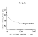
- FIG. 5 is another characteristic curve showing the relationship between the thickness of the reflecting layers and the energy resolution in the working example.
- 1 represents a photomultiplier tube
- 2 represents Bi4Ge3O12 crystal in rectangular parallelepiped form (referred to as BGO crystal) contacted to the entrance window 1a of the photomultiplier tube 1
- 3 represents reflecting layers of the BGO crystal 2 provided on faces other than a face contacted to the photomultiplier tube 1.
- the reflecting layers 3 consist of a reflecting agent and a polymer type binder.
- a paint of reflecting agent was prepared by mixing one volume part of liquid dispersion consisting of 1kg of powdered reflecting agent, 500g of water and 60g of 2.6% PVA aqueous solution and another one volume part of an acrylic type resin (NIPPEI HOME PAINT, a brand of NIPPON PAINT K. K.). This paint was coated on the five rough-polished faces by a means of a spray gun. After drying up the coated paint, the reflecting layers 3 were obtained on the 5 faces of the BGO crystal 2.
- an acrylic type resin as binder made it possible to have such layers by only once coating.
- the mirror polished face of this BGO crystal 2 was contacted to the photomultiplier tube 1 as shown in FIG. 1.
- a measuring system for an energy resolution of the above scintillator was build up as shown in FIG. 2.
- the energy resolution of the scintillator was then measured by using the system.
- the light generated by radiation of ⁇ -ray 4 irradiated onto the BGO crystal 2 was received and transferred to photo-electron by the photomultiplier tube 1.
- the photo-electron was amplified by the preamplifier 5 and the amplifier 6. Then the number of photons generated was counted up with the counter 7.
- the number 8 in the figure represents an electric source.
- pulse height produced per incidence ⁇ -ray was plotted on coordinate with the pulse height by incidence of the ⁇ - ray taken on an abscissa and the number of the incidence ⁇ -ray on the ordinate.
- FIG. 4 shows the results of measurement of this energy resolution using a wide variety of reflecting agents and varying the mean particle size thereof.
- the mean size of the agent is 0.8 ⁇ m or larger
- the energy resolution indicates a value 16% or less, which implies a good luminous efficiency and that the resolution is well stable.
- FIG. 5 indicates the result of measurement of energy resolution, made using BaSO4, 1 ⁇ m in mean particle size and varying the thickness of the reflecting layers 3.
- the energy resolution increases if the thickness is less than 50 ⁇ m, but it takes a stable value of less than 16% when the thickness is more than 50 ⁇ m. It was observed that any of these reflecting layers caused to grow no exfoliation nor crack.
- the BGO crystals 2 having the reflecting layers thus obtained were adhered with each other through intermediary of the layers with commonly used silicone-based adhesive "KE420" (brand of THE SHIN-ETSU CHEMICAL) and then assembled into a radiation detector. No exfoliation of the reflecting layers nor increased energy resolution was recognized.
- KE420 brand of THE SHIN-ETSU CHEMICAL
- the energy resolution of the radiation detector by this invention can be made smaller and stable by taken not less than 0.8 ⁇ m of the mean particle sizes of the reflecting agent that forms the reflecting layers provided on Bi4Ge3O12 crystal faces other than a face contacted to the entrance window of the photomultiplier tube, radiation can be detected with high accuracy.
- the detection accuracy can be improved since the energy resolution caused to be reduced and stabilized by raising the thickness of reflecting layers up to 50 ⁇ m or more.
- a binder for forming the reflecting layers of high polymer binder, more specifically acrylic resins, is effective in eliminating the influence of the silicone-based adhesive agent, which allows to enhance the reflectance and adhesion of the reflecting layers.
- a processing once suffices to build the reflecting layers thus resolving the problem of intricate manufacturing.
- a radiation detector comprising a photomultiplier tube, a Bi4Ge3O12 crystal of which a face contacted to the photomultiplier tube and reflecting layers which essentially consisting of reflecting powdery agent and an acrylic resin type binder provided on faces other than the face of the crystal, the energy resolution can be made smaller and stable. Thus, the resolution of the detector can be made higher.
- the detection accuracy can be improved since the energy resolution caused to be reduced and stabilized by raising the thickness of reflecting layers up to 50 ⁇ m or more.
- an acrylic resin, as a binder for forming the reflecting layers is effective in eliminating the influence of the silicone-based adhesive agent, which allows to enhance the reflectance and adhesion of the reflecting layers.
- a processing once suffices to build the reflecting layers thus resolving the problem of intricate manufacturing.
Description
- This invention relates to a radiation detector used in high energy physics or diagnostic radiology such as a X-ray computerized tomographic apparatus (X-ray CT) and a positron emission nuclide tomographic apparatus (positron CT).
- A radiation detector having a photomultiplier tube and a scintillator generates scintillation light by irradiated radiation and then the photons of the light are detected by the photomultiplier tube. The scintillator thus is required to meet the following conditions:
- (1) the scintillator should transmit to the photomultiplier tube the maximum of the fluorescence generated in itself, and
- (2) reflecting layers applied to the scintillator should be high in reflectance, stable and exempt from any alteration and discoloration, all over the ultraviolet to visible light range. Several types of scintillators satisfying these requirements have so far been commercialized.
- One of examples of such commercial use has been disclosed in Japanese Patent Provisional Publication No. 57-194374. The conventional radiation detector thus disclosed uses, as the reflecting layers of Bi₄Ge₃O₁₂ crystal (referred to as "BGO crystal" ), BaSO₄ with a binder consisting of polyvinyl alcohol (referred to as "PVA binder").
- A further prior art device is disclosed in US-A-4 543 485, which relates to a radiation detector comprising a photomultiplier tube, a scintillator crystal, such as a bismuth germanate (BGO) crystal, a face of which contacts the photomultiplier tube, and having a light reflective layer on faces other than the contacting face. The light reflective layer contains a powdery reflective agent dispersed in an organic binder such as ethyl cellulose, or an organic solvent such as terpineol. In order to improve the adhesive strength and the moisture resistance of the light reflective layer, a synthetic resin, such as an epoxy resin, an acrylic resin, or an urethane resin may be used as a protective outer layer of the radiation detector.
- The European patent application EP-A-0 146 255 discloses a formable light reflective composition which may be used as a radiation detector comprising a resin containing light-reflective solid particles having sizes of from 0.001 to 20 µm. Different flowable and curable resins comprising also polyacrylates may be used, but silicone type resins are preferred. This composition is used as a light reflective layer for preparing a radiation detector with sodium iodide, caesium fluoride, caesium iodide, barium fluoride and calcium fluoride as scintillation crystal.
- When forming conventional reflecting layers of BGO crystal from BaSO₄ with PVA binder, the reflectance of the reflecting layers is likely to fluctuate and the reflecting layers frequently exfoliate off the BGO crystal. These disadvantages are caused by permeation of adhesive material into the reflecting layers while they are made to adhere the BGO crystal to the photomultiplier tube by silicone-based adhesive commonly used. This permeation reduces the reflectance of the layers and adhesion.
- There is another disadvantage in the manufacturing process of conventional reflecting layers. The reflecting layers are made into multiple layers from aqueous solutions of different concentration of PVA mingled with BaSO₄ to be repeatedly coated thereon so many time that the process is onerous and expensive.
- This invention made to resolve such problematical points is intended to offer a radiation detector which meets the requirements of the scintillator, improves the reflecting properties and adhesiveness of the reflecting layers and can be readily manufactured. This is achieved by providing a radiation detector as defined in
Claim 1. - As the results of the present inventors' intense researches and studies made to have satisfactory reflecting layers of radiation detectors, the inventors found that the mean particle size of the reflecting agent has a significant influence upon the reflectance of the layers.
- As shown in Fig. 1, the radiation detector of this invention has a
photomultiplier tube 1, aBi₄Ge₃O₁₂ crystal 2 and reflectinglayers 3. The reflectinglayer 3 contains a reflecting agent and an acrylic resin type binder which are provided on surfaces other than the face of thecrystal 2 contacted to thephotomultiplier tube 1. The contacting face of the crystal is mirror polished and the other surfaces ore rough polished - The mean particle size of the reflecting agent is preferably not less than 0.8 µ m and that the binder is a polymer type binder.
- The thickness of the reflecting
layers 3 is preferably 50 µ m or more. - The mean particle sizes of the reflecting agent in the reflecting layers are more than 0.8 µ m so that the reflecting layers enhance the reflectance. This implies a greater number of photons which reach the photomultiplier tube and better energy resolution. If the mean sizes are less than this value, the energy resolution will be increased as described later, which in turn worsens the sensitivity of the radiation detector.
- Use of polymer type binder, more specifically an acrylic resin, as a binder to form the reflecting layers allows to avoid influence of the silicone-based adhesive and to improve the reflectance and adhesion of the reflecting layers. The thickness of the layers, which is more than 50 µ m, permits to obtain small enough an energy resolution. If the thickness of the layers is not more than 50 µ m, the scintillation in the BGO crystal leaks through the reflecting layers thereby rendering it impossible to have low enough an energy resolution.
- Thus the radiation detector of this invention presents a high enough sensitivity with its
energy resolution 16% or less. - The reflecting agents used are known materials such as BaSO₄, TiO₂, Al₂O₃, MgO and the like. Since the energy resolution increases if the mean particle sizes of these reflecting agents are 0.8 µ m or less. 0.8µ m or more of size, more preferably 0.8 to 2.5µ m thus is to be chosen.
- Use of acrylic resin based synthetic paints as polymer type binder enables to retain scintillation value of BGO crystal 2 as well as excellent adhesion and hardly allows crack. It does not permit such discoloration of paint film as in case of epoxy resins. Further use of silicone-based binder to adhere the
BGO crystal 2 onto thephotomultiplier tube 1 can avoid permeation of the binder and such trouble as exfoliation of the reflectinglayers 3. - The acrylic resins used are known materials such as polyacrylic acid esters: for instance, polymethylacrylate, polyethylacrylate, polybutylacrylate; emulsions and solvents which are of copolymerization type of these esters with acrylonitrile, vinyl acetate, vinyl chloride and the like.
- Because enough reduction of energy resolution cannot be had if the reflecting
layers 3 are 50 µ m or less in thickness, this thickness should be not less than 50µ m, more preferably 50 µ m to 200 µ m. Additionally, the reflectinglayers 3 may be overlaid with Teflon (Trade name; made by Du Pont Corporation) tape having reflective power. Furthermore, some parts of the reflectinglayers 3 may be used Teflon tape as changing from reflecting layers containing reflecting powder agents and acrylic resins. - This invention will be understood more easily by referring to the following working examples not limited with illustrations.
- FIG. 1 is a perspective illustration showing a working example of this invention, FIG. 2 is a block diagram showing a system of measurement, FIG. 3 represents a characteristic curve showing a relationship between a number of incidence γ -ray and pulse height generated by the γ -ray, FIG. 4 is a characteristic diagram showing the relationship between mean particle sizes of the reflecting layers and an energy resolution in the working example and FIG. 5 is another characteristic curve showing the relationship between the thickness of the reflecting layers and the energy resolution in the working example.
- In the FIG. 1, 1 represents a photomultiplier tube, 2 represents Bi₄Ge₃O₁₂ crystal in rectangular parallelepiped form (referred to as BGO crystal) contacted to the entrance window 1a of the
photomultiplier tube BGO crystal 2 provided on faces other than a face contacted to thephotomultiplier tube 1. The reflectinglayers 3 consist of a reflecting agent and a polymer type binder. - One face of 5 x 10 mm of a BGO crystal, which cut 5 x 10 x 25 mm of measure, was mirror polished and other 5 faces were rough polished. Thus the BGO crystal 2 as scintillator was prepared. A paint of reflecting agent was prepared by mixing one volume part of liquid dispersion consisting of 1kg of powdered reflecting agent, 500g of water and 60g of 2.6% PVA aqueous solution and another one volume part of an acrylic type resin (NIPPEI HOME PAINT, a brand of NIPPON PAINT K. K.). This paint was coated on the five rough-polished faces by a means of a spray gun. After drying up the coated paint, the reflecting
layers 3 were obtained on the 5 faces of theBGO crystal 2. Use of an acrylic type resin as binder made it possible to have such layers by only once coating. - The mirror polished face of this BGO crystal 2 was contacted to the
photomultiplier tube 1 as shown in FIG. 1. A measuring system for an energy resolution of the above scintillator was build up as shown in FIG. 2. The energy resolution of the scintillator was then measured by using the system. The light generated by radiation of γ -ray 4 irradiated onto theBGO crystal 2 was received and transferred to photo-electron by thephotomultiplier tube 1. The photo-electron was amplified by thepreamplifier 5 and theamplifier 6. Then the number of photons generated was counted up with thecounter 7. Thenumber 8 in the figure represents an electric source. - As shown in FIG. 3 pulse height produced per incidence γ -ray was plotted on coordinate with the pulse height by incidence of the γ - ray taken on an abscissa and the number of the incidence γ -ray on the ordinate. The energy resolution can be calculated in terms of the pulse peak E thus obtained and the half value width ΔE of the peak, from the following formula:
Energy resolution = ΔE/E (%) - The lower of the energy resolution, the resolution of the γ -ray detector is considered to be higher.
- FIG. 4 shows the results of measurement of this energy resolution using a wide variety of reflecting agents and varying the mean particle size thereof. As is clear from this figure, when the mean size of the agent is 0.8 µ m or larger, the energy resolution indicates a
value 16% or less, which implies a good luminous efficiency and that the resolution is well stable. - FIG. 5 indicates the result of measurement of energy resolution, made using BaSO₄, 1 µ m in mean particle size and varying the thickness of the reflecting layers 3. As is seen in this figure, the energy resolution increases if the thickness is less than 50µ m, but it takes a stable value of less than 16% when the thickness is more than 50µ m. It was observed that any of these reflecting layers caused to grow no exfoliation nor crack.
- The
BGO crystals 2 having the reflecting layers thus obtained were adhered with each other through intermediary of the layers with commonly used silicone-based adhesive "KE420" (brand of THE SHIN-ETSU CHEMICAL) and then assembled into a radiation detector. No exfoliation of the reflecting layers nor increased energy resolution was recognized. - For comparison, other reflecting layers were formed with PVA binder to examine their adhesiveness. These reflecting layers were readily exfoliated between themselves and the BGO crystal as a result of their similar adhesion to the above using a silicone-based binder.
- As the explained the above, since the energy resolution of the radiation detector by this invention can be made smaller and stable by taken not less than 0.8 µ m of the mean particle sizes of the reflecting agent that forms the reflecting layers provided on Bi₄Ge₃O₁₂ crystal faces other than a face contacted to the entrance window of the photomultiplier tube, radiation can be detected with high accuracy.
- The detection accuracy can be improved since the energy resolution caused to be reduced and stabilized by raising the thickness of reflecting layers up to 50 µ m or more. Furthermore use, as a binder for forming the reflecting layers, of high polymer binder, more specifically acrylic resins, is effective in eliminating the influence of the silicone-based adhesive agent, which allows to enhance the reflectance and adhesion of the reflecting layers. At the same time, a processing once suffices to build the reflecting layers thus resolving the problem of intricate manufacturing.
- By a radiation detector comprising a photomultiplier tube, a Bi₄Ge₃O₁₂ crystal of which a face contacted to the photomultiplier tube and reflecting layers which essentially consisting of reflecting powdery agent and an acrylic resin type binder provided on faces other than the face of the crystal, the energy resolution can be made smaller and stable. Thus, the resolution of the detector can be made higher.
- The detection accuracy can be improved since the energy resolution caused to be reduced and stabilized by raising the thickness of reflecting layers up to 50 µ m or more. Furthermore use of an acrylic resin, as a binder for forming the reflecting layers, is effective in eliminating the influence of the silicone-based adhesive agent, which allows to enhance the reflectance and adhesion of the reflecting layers. At the same time, a processing once suffices to build the reflecting layers thus resolving the problem of intricate manufacturing.
Claims (5)
- A radiation detector comprising a photomultiplier tube (1), a multiface Bi₄Ge₃O₁₂ crystal (2), a face of which contacts the photomultiplier tube, and reflecting layers (3) containing a reflecting powdery agent and a binder on faces other than the contacting face, characterized in that said contacting face is mirror polished and said other surfaces are rough polished, and said binder contains an acrylic resin.
- The radiation detector according to claim 1, wherein the reflecting powdery agent has the mean particle sizes of 0.8 µm to 2.5 µm.
- The radiation detector according to claim 1, wherein the reflecting powdery agent is at least one selected from the group consisting of BaSO₄, TiO₂, Al₂O₃ and MgO.
- The radiation detector according to claim 1, wherein the acrylic resin is at least one selected from the group consisting of polymethylacrylate, polyethylacrylate, polybutylacrylate and copolymer of acrylonitrile, vinyl acetate and vinyl chloride with said acrylates.
- The radiation detector according to claim 1, wherein thickness of the reflecting layers (3) is not less than 50 µm.
Applications Claiming Priority (2)
| Application Number | Priority Date | Filing Date | Title |
|---|---|---|---|
| JP86793/89 | 1989-04-07 | ||
| JP1086793A JPH02266287A (en) | 1989-04-07 | 1989-04-07 | Radiation detector |
Publications (2)
| Publication Number | Publication Date |
|---|---|
| EP0391237A1 EP0391237A1 (en) | 1990-10-10 |
| EP0391237B1 true EP0391237B1 (en) | 1993-07-21 |
Family
ID=13896660
Family Applications (1)
| Application Number | Title | Priority Date | Filing Date |
|---|---|---|---|
| EP90105949A Expired - Lifetime EP0391237B1 (en) | 1989-04-07 | 1990-03-28 | Radiation detector |
Country Status (4)
| Country | Link |
|---|---|
| US (1) | US5061855A (en) |
| EP (1) | EP0391237B1 (en) |
| JP (1) | JPH02266287A (en) |
| DE (1) | DE69002265T2 (en) |
Families Citing this family (19)
| Publication number | Priority date | Publication date | Assignee | Title |
|---|---|---|---|---|
| EP0535634B1 (en) * | 1991-10-03 | 1998-06-10 | Kabushiki Kaisha Toshiba | Radiation detector and its manufacturing method |
| JP3220245B2 (en) * | 1992-08-10 | 2001-10-22 | 浜松ホトニクス株式会社 | Photomultiplier tube |
| JPH06103959A (en) * | 1992-09-21 | 1994-04-15 | Hamamatsu Photonics Kk | Collecting device for photo-electron multiplier tube |
| DE4301177A1 (en) * | 1993-01-19 | 1994-07-21 | Telefunken Microelectron | UV radiation detector of high sensitivity |
| DE4327752A1 (en) * | 1993-08-18 | 1995-02-23 | Taurus Daten & Mestechnik Gmbh | Radiation measuring device for luminescence and fluorescence measurement |
| FR2718852B1 (en) * | 1994-04-19 | 1996-05-15 | Commissariat Energie Atomique | Remote radiation detection device. |
| US5483070A (en) * | 1994-08-02 | 1996-01-09 | Packard Instrument Company | Scintillation counter |
| US7157014B1 (en) * | 2001-10-05 | 2007-01-02 | Cit Pet Systems, Inc. | Method for producing a high resolution detector array |
| US20030178570A1 (en) * | 2002-03-25 | 2003-09-25 | Hitachi Metals, Ltd. | Radiation detector, manufacturing method thereof and radiation CT device |
| US7420162B2 (en) * | 2004-06-30 | 2008-09-02 | Siemens Medical Solutions Usa, Inc. | Systems and methods for creating stable camera optics |
| DE102005035421A1 (en) * | 2005-07-28 | 2007-02-08 | Siemens Ag | Moldable and curing reflector material with increased reflectivity |
| US7780912B2 (en) * | 2005-08-26 | 2010-08-24 | Lawrence Livermore National Security, Llc | Paint for detection of radiological or chemical agents |
| JP2009264751A (en) * | 2008-04-21 | 2009-11-12 | Furukawa Co Ltd | Method for manufacturing of scintillator, the scintillator, application liquid for the scintillator, and method for preparing the liquid |
| JP5317675B2 (en) * | 2008-12-22 | 2013-10-16 | 株式会社東芝 | Radiation detector and manufacturing method thereof |
| US9310323B2 (en) | 2009-05-16 | 2016-04-12 | Rapiscan Systems, Inc. | Systems and methods for high-Z threat alarm resolution |
| GB201312352D0 (en) * | 2013-07-10 | 2013-08-21 | Rapiscan Systems Ltd | Radiation detection |
| US9557427B2 (en) | 2014-01-08 | 2017-01-31 | Rapiscan Systems, Inc. | Thin gap chamber neutron detectors |
| FR3057073B1 (en) * | 2016-09-30 | 2021-05-07 | Damavan Imaging | DEVICE AND SYSTEM FOR DETECTION OF IONIZING RADIATION AND NEUTRONS |
| CN112540395A (en) * | 2020-12-04 | 2021-03-23 | 清远先导材料有限公司 | Scintillation crystal array and method of assembling and disassembling the same |
Family Cites Families (7)
| Publication number | Priority date | Publication date | Assignee | Title |
|---|---|---|---|---|
| NL7802916A (en) * | 1978-03-17 | 1979-09-19 | Philips Nv | RADIANT DRAWER DEVICE. |
| US4375423A (en) * | 1980-07-15 | 1983-03-01 | General Electric Company | Index-matched phosphor scintillator structures |
| US4543485A (en) * | 1981-11-24 | 1985-09-24 | Hitachi Chemical Company, Ltd. | Scintillator for radiation detection and process for producing the same |
| US4647781A (en) * | 1983-01-31 | 1987-03-03 | Hitachi Chemical Company, Ltd. | Gamma ray detector |
| US4533489A (en) * | 1983-12-07 | 1985-08-06 | Harshaw/Filtrol Partnership | Formable light reflective compositions |
| US4733088A (en) * | 1985-09-02 | 1988-03-22 | Hitachi, Ltd. | Radiation detector |
| US4788436A (en) * | 1986-12-24 | 1988-11-29 | Walter Koechner | Radiation sensitive optical fiber and detector |
-
1989
- 1989-04-07 JP JP1086793A patent/JPH02266287A/en active Granted
-
1990
- 1990-03-28 DE DE90105949T patent/DE69002265T2/en not_active Expired - Fee Related
- 1990-03-28 EP EP90105949A patent/EP0391237B1/en not_active Expired - Lifetime
- 1990-04-09 US US07/506,864 patent/US5061855A/en not_active Expired - Lifetime
Also Published As
| Publication number | Publication date |
|---|---|
| DE69002265D1 (en) | 1993-08-26 |
| EP0391237A1 (en) | 1990-10-10 |
| US5061855A (en) | 1991-10-29 |
| DE69002265T2 (en) | 1993-11-25 |
| JPH0575991B2 (en) | 1993-10-21 |
| JPH02266287A (en) | 1990-10-31 |
Similar Documents
| Publication | Publication Date | Title |
|---|---|---|
| EP0391237B1 (en) | Radiation detector | |
| CA2619931C (en) | Paint for detection of corrosion and warning of chemical and radiological attack | |
| US9211565B2 (en) | Adhesive layer for digital detectors | |
| US4658141A (en) | Inorganic scintillator crystal having a highly reflective surface | |
| US4066908A (en) | Well-type scintillation assembly | |
| EP1550885B1 (en) | Phosphor sheet for radiation detector, radiation detector employing it and equipment for detecting radiation | |
| US4631409A (en) | Scintillator crystal having a highly reflective surface | |
| NL8204539A (en) | SCINTILLATOR AND METHOD FOR MANUFACTURING THAT. | |
| US20130092828A1 (en) | Scintillation detection device with pressure sensitive adhesive interfaces | |
| AU715316B2 (en) | Scintillator apparatus | |
| EP1183554A1 (en) | In-situ radioactivity detection | |
| JPS63129304A (en) | Scintillator fiber having high light emission efficiency | |
| JP2000258539A (en) | Apparatus and method for detection of radiation | |
| US20170168165A1 (en) | Scintillation device with moisture barrier | |
| JP2000235078A (en) | Radiation detecting structural body, and radiation detector and radiation inspection device using same | |
| EP0752711B1 (en) | Antistatic X-ray intensifying screen comprising fluoroalkylsulfonate salts | |
| JP5655030B2 (en) | System and method for warning that a person is facing radioactive material | |
| JPH0634761A (en) | Method of measuring distribution of radioactive contamination | |
| Bolton et al. | A 207Bi light pulser for stabilization of scintillation and lead glass Cherenkov detectors | |
| JPH0651068A (en) | Manufacture of radiation sensor | |
| JPH03239786A (en) | Scintillator and radiation detector using scintillator | |
| KR100639418B1 (en) | Thin film zns(ag) scintillator for detection of alpha paticles, and preparation method thereof | |
| JPS5888684A (en) | Scintillator for radiation detection | |
| Bauer et al. | Scintillation Characteristics of Thin NaI (Tl) and CsI (Tl) Layers Fabricated by Vacuum Deposition | |
| Farukhi et al. | Well-type scintillation assembly |
Legal Events
| Date | Code | Title | Description |
|---|---|---|---|
| PUAI | Public reference made under article 153(3) epc to a published international application that has entered the european phase |
Free format text: ORIGINAL CODE: 0009012 |
|
| AK | Designated contracting states |
Kind code of ref document: A1 Designated state(s): DE FR GB |
|
| 17P | Request for examination filed |
Effective date: 19910321 |
|
| 17Q | First examination report despatched |
Effective date: 19920225 |
|
| GRAA | (expected) grant |
Free format text: ORIGINAL CODE: 0009210 |
|
| AK | Designated contracting states |
Kind code of ref document: B1 Designated state(s): DE FR GB |
|
| ET | Fr: translation filed | ||
| REF | Corresponds to: |
Ref document number: 69002265 Country of ref document: DE Date of ref document: 19930826 |
|
| PLBE | No opposition filed within time limit |
Free format text: ORIGINAL CODE: 0009261 |
|
| STAA | Information on the status of an ep patent application or granted ep patent |
Free format text: STATUS: NO OPPOSITION FILED WITHIN TIME LIMIT |
|
| 26N | No opposition filed | ||
| PGFP | Annual fee paid to national office [announced via postgrant information from national office to epo] |
Ref country code: FR Payment date: 19990309 Year of fee payment: 10 |
|
| PGFP | Annual fee paid to national office [announced via postgrant information from national office to epo] |
Ref country code: GB Payment date: 19990401 Year of fee payment: 10 |
|
| PGFP | Annual fee paid to national office [announced via postgrant information from national office to epo] |
Ref country code: DE Payment date: 19990406 Year of fee payment: 10 |
|
| PG25 | Lapsed in a contracting state [announced via postgrant information from national office to epo] |
Ref country code: GB Free format text: LAPSE BECAUSE OF NON-PAYMENT OF DUE FEES Effective date: 20000328 |
|
| GBPC | Gb: european patent ceased through non-payment of renewal fee |
Effective date: 20000328 |
|
| PG25 | Lapsed in a contracting state [announced via postgrant information from national office to epo] |
Ref country code: FR Free format text: LAPSE BECAUSE OF NON-PAYMENT OF DUE FEES Effective date: 20001130 |
|
| REG | Reference to a national code |
Ref country code: FR Ref legal event code: ST |
|
| PG25 | Lapsed in a contracting state [announced via postgrant information from national office to epo] |
Ref country code: DE Free format text: LAPSE BECAUSE OF NON-PAYMENT OF DUE FEES Effective date: 20010103 |