EP0389955A2 - A double locking connector for an electrical terminal - Google Patents
A double locking connector for an electrical terminal Download PDFInfo
- Publication number
- EP0389955A2 EP0389955A2 EP90105382A EP90105382A EP0389955A2 EP 0389955 A2 EP0389955 A2 EP 0389955A2 EP 90105382 A EP90105382 A EP 90105382A EP 90105382 A EP90105382 A EP 90105382A EP 0389955 A2 EP0389955 A2 EP 0389955A2
- Authority
- EP
- European Patent Office
- Prior art keywords
- terminal
- engagement
- flexible
- arm
- engagement arm
- Prior art date
- Legal status (The legal status is an assumption and is not a legal conclusion. Google has not performed a legal analysis and makes no representation as to the accuracy of the status listed.)
- Granted
Links
Images

Classifications
-
- H—ELECTRICITY
- H01—ELECTRIC ELEMENTS
- H01R—ELECTRICALLY-CONDUCTIVE CONNECTIONS; STRUCTURAL ASSOCIATIONS OF A PLURALITY OF MUTUALLY-INSULATED ELECTRICAL CONNECTING ELEMENTS; COUPLING DEVICES; CURRENT COLLECTORS
- H01R13/00—Details of coupling devices of the kinds covered by groups H01R12/70 or H01R24/00 - H01R33/00
- H01R13/40—Securing contact members in or to a base or case; Insulating of contact members
- H01R13/42—Securing in a demountable manner
- H01R13/436—Securing a plurality of contact members by one locking piece or operation
- H01R13/4364—Insertion of locking piece from the front
- H01R13/4365—Insertion of locking piece from the front comprising a temporary and a final locking position
-
- H—ELECTRICITY
- H01—ELECTRIC ELEMENTS
- H01R—ELECTRICALLY-CONDUCTIVE CONNECTIONS; STRUCTURAL ASSOCIATIONS OF A PLURALITY OF MUTUALLY-INSULATED ELECTRICAL CONNECTING ELEMENTS; COUPLING DEVICES; CURRENT COLLECTORS
- H01R13/00—Details of coupling devices of the kinds covered by groups H01R12/70 or H01R24/00 - H01R33/00
- H01R13/40—Securing contact members in or to a base or case; Insulating of contact members
- H01R13/42—Securing in a demountable manner
- H01R13/422—Securing in resilient one-piece base or case, e.g. by friction; One-piece base or case formed with resilient locking means
-
- H—ELECTRICITY
- H01—ELECTRIC ELEMENTS
- H01R—ELECTRICALLY-CONDUCTIVE CONNECTIONS; STRUCTURAL ASSOCIATIONS OF A PLURALITY OF MUTUALLY-INSULATED ELECTRICAL CONNECTING ELEMENTS; COUPLING DEVICES; CURRENT COLLECTORS
- H01R13/00—Details of coupling devices of the kinds covered by groups H01R12/70 or H01R24/00 - H01R33/00
- H01R13/40—Securing contact members in or to a base or case; Insulating of contact members
- H01R13/42—Securing in a demountable manner
- H01R13/428—Securing in a demountable manner by resilient locking means on the contact members; by locking means on resilient contact members
Definitions
- the present invention relates to a double locking structure for terminal in electrical connectors which is simple in construction and provides a large locking force without increasing a resistance against the terminal being inserted into a terminal accommodating chamber of a connector housing, thereby reliably preventing the terminal from slipping off from the rear of the connector.
- a common method of fixing the terminal in the electrical connector and preventing it from slipping off from the back of the connector is by integrally forming a forwardly extending flexible engagement arm on the inner wall of the terminal accommodating chamber, so that the flexible engagement arm is engaged with the terminal inserted into the terminal accommodating chamber.
- the Japanese Patent Publication No. Showa 54-24116 proposes a structure in which flexible engagement arms are provided to both side walls of the terminal accommodating chamber so as to hold the terminal from both sides.
- the Japanese Utility Publication No. Showa 54-44779 discloses a structure in which a leaf-spring-shaped housing lance (flexible engagement arm) formed in the connector housing and a leaf-spring-shaped terminal lance formed on the terminal provide a double locking for the terminal.
- the housing or terminal lances increase the terminal fixing force
- drawbacks such as a large insertion force required to insert the terminal, an increase in the size of the terminal accommodating chamber, and a complex internal structure of the chamber.
- the Japanese Utility Model Preliminary Publication No. Showa 61-7875 discloses a structure in which a lock member is inserted between the flexible engagement arm and the inner wall of the terminal accommodating chamber, to prevent deflection of the flexible engagement arm toward the inner wall thereby providing a secure locking of the terminal.
- This invention has been accomplished to eliminate such drawbacks and offer a terminal double-locking structure in electrical connectors which has a simple inner structure of the terminal accommodating chamber, which allows the terminal to be inserted with a small insertion force, and which provides a double locking and large fixing force for the terminal, ensuring a stable electrical connection.
- this invention provides a double locking structure for terminal in electrical connectors, which comprises: a connector housing having a terminal accommodating chamber therein; a flexible engagement arm provided to the inner wall of the terminal accommodating chamber of the connector housing, the flexible arm extending forwardly; a first engagement projection formed at the free end of the flexible engagement arm, the first engagement projection being adapted to engage with an engagement hole or recess formed in the terminal inserted in the terminal accommodating chamber; a second engagement projection formed at least at one side of the flexible engagement arm; and an engagement piece formed in the terminal, the engagement piece being adapted to engage with the second engagement projection; whereby the first and second engagement projections cooperate to doubly prevent the terminal from slipping off from the rear of the connector.
- the second engagement projection is provided between the first engagement projection and a fulcrum of the flexible engagement arm, the apex of the second engagement projection is set lower than the upper surface of the flexible engagement arm, and the rear part of the second engagement projection is preferably formed into a tapered slope.
- a lock member be inserted to prevent the flexible engagement arm from deflecting.
- the terminal is doubly locked by the first and second engagement projections of the flexible engagement arm to reliably prevent the terminal from slipping off from the back of the connector.
- the second engagement projection need only be provided at one or both sides of the flexible engagement arm, so that the internal structure of the terminal accommodating chamber will not be modified significantly, requiring only a partial change in the design of an insert of the die. The same also applies to the engagement piece on the terminal.
- reference symbol A represents a synthetic resin male connector housing, B a terminal, and C a synthetic resin lock member.
- the male connector housing A is adapted to be engaged with a mating female connector housing not shown.
- the connector housing A there is a terminal accommodating chamber 1 that opens at the front and at the back. On the outside, the connector housing A has a locking arm 2 to lock the female connector housing.
- the terminal accommodating chamber 1 has a stopper wall 3 at the front opening and has upper and lower opposing inner walls 4, 5.
- One of the inner walls 4 is formed integral with a flexible engagement arm 6 that resiliently deflects between the wall 4 and the other opposing wall 5.
- the flexible engagement arm 6 has a first engagement projection 7 at the top of its end and second engagement projections 8 integrally formed on each side at the back of the first projection 7.
- the second engagement projections 8 are shaped into a triangle having a vertical shoulder surface 8a at the front side and a moderately tapered slope 8b at the rear side.
- the apex 8c of the second projection 8 is set slightly lower than the upper surface 6a of the flexible engagement arm 6.
- the terminal B consists of a base plate 9, an electric contact portion B1 formed at the front of the base plate 9, and an electric connector portion B2 at the back, these three parts being integrally formed as one piece.
- the electric connector portion B2 is connected with a wire 18 through a water-proof rubber plug 17.
- the electric contact portion B1 consists of: a cylindrical tab receiving portion 11 formed by bending the upper portion of erect side walls 10 on each side of the base plate 9; and a resilient tongue 12 formed by folding the front end of the base plate 9 back into the tab receiving portion 11. The free end of the resilient tongue 12 is further folded toward the base plate 9 to form a resilient support piece 13.
- the base plate 9 is formed with an engagement hole 14 to accept the flexible engagement arm 6.
- the engagement pieces 15 may be the erected pieces of the base plate 9 that are produced when making the engagement hole 14.
- the lock member C is a plate member which has an insertion guide tapered surface 16 at the front end.
- the thickness of the lock member, t is set slightly larger than t′, a gap between the flexible engagement arm 6 and the inner wall 4.
- the lock member C inserted into the terminal accommodating chamber 1 from the front opening is temporarily locked at a position slightly away from the front end of the flexible engagement arm 6.
- the base plate 9 advances inwardly sliding on the upper surface 6a of the flexible engagement arm 6 and reaches the upper slant surface of the first engagement projection 7, pressing the projection to deflect the flexible engagement arm 6 toward the inner wall 4.
- the engagement pieces 15 hold the flexible engagement arm 6 from both sides, thus eliminating the lateral play of the terminal B to help maintain its stable attitude.
- the terminal B is shown to be a female terminal with a tab receiving portion 11, the invention can also be applied to male terminals. It is also possible to employ a construction in which the flexible engagement arm 6 is provided to the other inner wall 5 so that the first engagement projection 7 of the arm will engage with the shoulder 11a of the tab receiving portion 11. In stead of forming the rear part of the second engagement projections 8 into the tapered slopes 8b, the front part of the engagement projections 15 of the terminal B may be tapered. Or both of them may be tapered.
Abstract
Description
- The present invention relates to a double locking structure for terminal in electrical connectors which is simple in construction and provides a large locking force without increasing a resistance against the terminal being inserted into a terminal accommodating chamber of a connector housing, thereby reliably preventing the terminal from slipping off from the rear of the connector.
- A common method of fixing the terminal in the electrical connector and preventing it from slipping off from the back of the connector is by integrally forming a forwardly extending flexible engagement arm on the inner wall of the terminal accommodating chamber, so that the flexible engagement arm is engaged with the terminal inserted into the terminal accommodating chamber.
- However, a single-step flexible engagement arm can provide only a weak locking force, so the terminal may come off. To prevent this, some proposals have been made. For example, the Japanese Patent Publication No. Showa 54-24116 proposes a structure in which flexible engagement arms are provided to both side walls of the terminal accommodating chamber so as to hold the terminal from both sides. The Japanese Utility Publication No. Showa 54-44779 discloses a structure in which a leaf-spring-shaped housing lance (flexible engagement arm) formed in the connector housing and a leaf-spring-shaped terminal lance formed on the terminal provide a double locking for the terminal. In these cases, while the housing or terminal lances increase the terminal fixing force, there are drawbacks, such as a large insertion force required to insert the terminal, an increase in the size of the terminal accommodating chamber, and a complex internal structure of the chamber.
- Structures intended to provide a double terminal locking without increasing the terminal insertion resistance have been proposed. In the Japanese Utility Model Publication No. Showa 54-28625, for example, a through-hole is provided to the connector housing and a pin is inserted through the hole and engaged with a stepped shoulder portion of the electrical contact of the terminal. The Japanese Utility Model Publication No. Showa 60-31171 discloses a structure in which a terminal retainer portion having projected strips for pressing the terminal and also a locking means is mounted, through a hinge, to the rear part of the housing (on the wire connection side) so that the terminal retainer portion can be opened and closed. These constructions, however, increase the number of parts used in the electrical connector as well as the assembly processes and cost, which in turn increases the size of the housing and complicates the internal structure.
- As a means of increasing the terminal fixing force without affecting the terminal insertion resistance and the internal structure, the Japanese Utility Model Preliminary Publication No. Showa 61-7875 discloses a structure in which a lock member is inserted between the flexible engagement arm and the inner wall of the terminal accommodating chamber, to prevent deflection of the flexible engagement arm toward the inner wall thereby providing a secure locking of the terminal.
- Even with the lock member inserted between the flexible engagement arm -which engages with the terminal- and the inner wall, the terminal is held by only one engagement projection formed on the flexible engagement arm. This engagement projection is limited in size by the dimensional relationship to the terminal and may be cracked or damaged by a large tension on the connected wire, resulting in the terminal slipping off. Such a connector therefore cannot provide a sufficiently large terminal fixing force.
- This invention has been accomplished to eliminate such drawbacks and offer a terminal double-locking structure in electrical connectors which has a simple inner structure of the terminal accommodating chamber, which allows the terminal to be inserted with a small insertion force, and which provides a double locking and large fixing force for the terminal, ensuring a stable electrical connection.
- To achieve the above objectives, this invention provides a double locking structure for terminal in electrical connectors, which comprises: a connector housing having a terminal accommodating chamber therein; a flexible engagement arm provided to the inner wall of the terminal accommodating chamber of the connector housing, the flexible arm extending forwardly; a first engagement projection formed at the free end of the flexible engagement arm, the first engagement projection being adapted to engage with an engagement hole or recess formed in the terminal inserted in the terminal accommodating chamber; a second engagement projection formed at least at one side of the flexible engagement arm; and an engagement piece formed in the terminal, the engagement piece being adapted to engage with the second engagement projection; whereby the first and second engagement projections cooperate to doubly prevent the terminal from slipping off from the rear of the connector.
- To avoid an increase in resistance against the terminal being inserted into the terminal accommodating chamber, the second engagement projection is provided between the first engagement projection and a fulcrum of the flexible engagement arm, the apex of the second engagement projection is set lower than the upper surface of the flexible engagement arm, and the rear part of the second engagement projection is preferably formed into a tapered slope.
- To increase the fixing or locking force on the terminal, it is desired that a lock member be inserted to prevent the flexible engagement arm from deflecting.
- With this invention, the terminal is doubly locked by the first and second engagement projections of the flexible engagement arm to reliably prevent the terminal from slipping off from the back of the connector.
- The second engagement projection need only be provided at one or both sides of the flexible engagement arm, so that the internal structure of the terminal accommodating chamber will not be modified significantly, requiring only a partial change in the design of an insert of the die. The same also applies to the engagement piece on the terminal.
- It is easy to provide a construction where the second engagement projection is kept out of contact with the engagement piece until the first engagement projection engages with the terminal when the terminal is inserted into the terminal accommodating chamber. In this structure, the terminal can be inserted with the same inserting force as required in the conventional connectors.
- When the lock member, which prevents deflection of the flexible engagement arm, is used in combination with the above engagement mechanism, the fixing force on the terminal will further increase.
- The construction and features of this invention will be described in detail by referring to the attached drawings showing one embodiment of the invention.
-
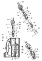
- Figure 1 is a cross section of the connector according to the invention with the terminal separated;
- Figure 2 is a perspective view of essential portions of Figure 1;
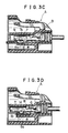
- Figures 3A to 3D are cross sections showing how the terminal is secured and locked; and
- Figure 4 is a perspective view of essential portions of Figure 3 with the terminal connected.
-
- Referring to Figures 1 and 2, reference symbol A represents a synthetic resin male connector housing, B a terminal, and C a synthetic resin lock member. The male connector housing A is adapted to be engaged with a mating female connector housing not shown.
- In the connector housing A there is a terminal accommodating chamber 1 that opens at the front and at the back. On the outside, the connector housing A has a locking arm 2 to lock the female connector housing.
- The terminal accommodating chamber 1 has a
stopper wall 3 at the front opening and has upper and lower opposing inner walls 4, 5. One of the inner walls 4 is formed integral with aflexible engagement arm 6 that resiliently deflects between the wall 4 and the other opposing wall 5. - The
flexible engagement arm 6 has afirst engagement projection 7 at the top of its end andsecond engagement projections 8 integrally formed on each side at the back of thefirst projection 7. Thesecond engagement projections 8 are shaped into a triangle having avertical shoulder surface 8a at the front side and a moderatelytapered slope 8b at the rear side. Theapex 8c of thesecond projection 8 is set slightly lower than theupper surface 6a of theflexible engagement arm 6. - The terminal B consists of a
base plate 9, an electric contact portion B₁ formed at the front of thebase plate 9, and an electric connector portion B₂ at the back, these three parts being integrally formed as one piece. The electric connector portion B₂ is connected with awire 18 through a water-proof rubber plug 17. - The electric contact portion B₁ consists of: a cylindrical
tab receiving portion 11 formed by bending the upper portion oferect side walls 10 on each side of thebase plate 9; and aresilient tongue 12 formed by folding the front end of thebase plate 9 back into thetab receiving portion 11. The free end of theresilient tongue 12 is further folded toward thebase plate 9 to form aresilient support piece 13. - At the electric contact portion B₁, the
base plate 9 is formed with anengagement hole 14 to accept theflexible engagement arm 6. On each side of thehole 14, there areengagement pieces 15 projecting downwardly. Theengagement pieces 15 may be the erected pieces of thebase plate 9 that are produced when making theengagement hole 14. - The lock member C is a plate member which has an insertion guide tapered
surface 16 at the front end. The thickness of the lock member, t, is set slightly larger than t′, a gap between theflexible engagement arm 6 and the inner wall 4. - Next, the double locking of the terminal will be explained by referring to Figures 3A to 3D.
- As shown in Figure 3A, the lock member C inserted into the terminal accommodating chamber 1 from the front opening is temporarily locked at a position slightly away from the front end of the
flexible engagement arm 6. As the terminal B is inserted, as shown in Figure 3B, thebase plate 9 advances inwardly sliding on theupper surface 6a of theflexible engagement arm 6 and reaches the upper slant surface of thefirst engagement projection 7, pressing the projection to deflect theflexible engagement arm 6 toward the inner wall 4. - Then as shown in Figure 3C, when the terminal B further advances and the
base plate 9 contacts thetop surface 7a of thefirst engagement projection 7, theapexes 8c of thesecond engagement projections 8 come close to the lower ends of theengagement pieces 15. - In the process intermediate between Figure 3B and 3C, the lower ends of the
engagement pieces 15 pass over thetapered slopes 8b at the rear of thesecond engagement projections 8. The contact between thebase plate 9 and thefirst projection 7 and between theengagement pieces 15 of the terminal B and thesecond engagement projections 8 is both made through line or point contact. Thus the contact resistance is small. - When the
engagement hole 14 reaches thefirst engagement projection 7, theflexible engagement arm 6 snaps back to its original shape by elasticity. As a result, as shown in Figures 3D and 4, thefirst engagement projection 7 engages with theengagement hole 14 of the terminal B and almost at the same time the vertical shoulder surfaces 8a of thesecond engagement projections 8 engage with the rear edges of theengagement pieces 15, providing a double locking of the terminal B. In this double-locking condition, the lock member C is further inserted with force between theflexible engagement arm 6 and the inner wall 4 to securely lock the terminal B. This prevents theflexible engagement arm 6 from being deflected toward the inner wall 4. - Not only is the terminal B doubly locked by the
flexible engagement arm 6 and by the engagement between theengagement pieces 15 and thesecond engagement projections 8, but theflexible engagement arm 6 is also locked from deflection by the insertion of the lock member C. This combination of locking mechanisms increases the fixing force of the connector. - When the terminal B is inserted imperfectly, the engagement between the
engagement pieces 15 of the terminal B and thetapered slopes 8b of thesecond engagement projections 8 will deflect theflexible engagement arm 6 toward the inner wall 4 to such an extent that the lock member C cannot be inserted. This prevents any incomplete terminal connection. - Furthermore, with the terminal B completely inserted, the
engagement pieces 15 hold theflexible engagement arm 6 from both sides, thus eliminating the lateral play of the terminal B to help maintain its stable attitude. - While in the above embodiment the terminal B is shown to be a female terminal with a
tab receiving portion 11, the invention can also be applied to male terminals. It is also possible to employ a construction in which theflexible engagement arm 6 is provided to the other inner wall 5 so that thefirst engagement projection 7 of the arm will engage with the shoulder 11a of thetab receiving portion 11. In stead of forming the rear part of thesecond engagement projections 8 into thetapered slopes 8b, the front part of theengagement projections 15 of the terminal B may be tapered. Or both of them may be tapered. - As described above, with this invention, it is possible to avoid an increase in the size of the terminal accommodating chamber and in the complexity of the internal structure, to allow the terminal to be inserted with a force comparable to that with the conventional connectors, and to prevent the terminal from slipping off from the rear part of the connector by double (or triple) locking, thereby reinforcing the terminal fixing force and substantially improving the reliability of electrical connection.
Claims (5)
- (1) A double locking structure for terminal in electrical connectors, comprising:
a connector housing having a terminal accommodating chamber therein;
a flexible engagement arm provided at an inner wall of the terminal accommodating chamber of the connector housing, said flexible arm extending forwardly;
a first engagement projection formed at a free end of the flexible engagement arm, the first engagement projection being adapted to engage with an engagement hole or recess formed in the terminal inserted in the terminal accommodating chamber;
a second engagement projection formed at least at one side of the flexible engagement arm; and
an engagement piece formed in the terminal, the engagement piece being adapted to engage with the second engagement projection;
whereby the first and second engagement projections cooperate to doubly prevent the terminal from slipping off from the rear of the connector. - (2) A double locking structure for terminal in electri cal connectors, as set forth in claim 1, wherein the second engagement projection is provided between a fulcrum of the flexible engagement arm and the first engagement projection.
- (3) A double locking structure for terminal in electrical connectors, as set forth in claim 1 or 2, wherein the apex of the second engagement projection is set lower than the upper surface of the flexible engagement arm.
- (4) A double locking structure for terminal in electrical connectors, as set forth in claim 1, 2 or 3, wherein the second engagement projection has its front part formed into a vertical shoulder surface and the rear part into a tapered slope.
- (5) A double locking structure for terminal in electrical connectors, as set forth in claim 1, 2, 3 or 4, wherein when the flexible engagement arm and the terminal are engaged, a lock member is inserted between the flexible engagement arm and the inner wall of the terminal accommodating chamber to prevent deflection of the flexible engagement arm.
Applications Claiming Priority (2)
| Application Number | Priority Date | Filing Date | Title |
|---|---|---|---|
| JP1989034809U JP2519179Y2 (en) | 1989-03-29 | 1989-03-29 | Double locking structure for terminal fittings in electrical connectors |
| JP34809/89U | 1989-03-29 |
Publications (3)
| Publication Number | Publication Date |
|---|---|
| EP0389955A2 true EP0389955A2 (en) | 1990-10-03 |
| EP0389955A3 EP0389955A3 (en) | 1991-09-04 |
| EP0389955B1 EP0389955B1 (en) | 1995-06-07 |
Family
ID=12424544
Family Applications (1)
| Application Number | Title | Priority Date | Filing Date |
|---|---|---|---|
| EP90105382A Expired - Lifetime EP0389955B1 (en) | 1989-03-29 | 1990-03-21 | A double locking connector for an electrical terminal |
Country Status (5)
| Country | Link |
|---|---|
| US (1) | US4969841A (en) |
| EP (1) | EP0389955B1 (en) |
| JP (1) | JP2519179Y2 (en) |
| CA (1) | CA2012167C (en) |
| DE (1) | DE69019856T2 (en) |
Cited By (8)
| Publication number | Priority date | Publication date | Assignee | Title |
|---|---|---|---|---|
| EP0511510A2 (en) * | 1991-04-29 | 1992-11-04 | Grote & Hartmann GmbH & Co. KG | Electrical plug housing with means of alignment for the insertion of a terminal in a terminal accommodating chamber |
| DE4230333A1 (en) * | 1991-09-11 | 1993-03-25 | Yazaki Corp | Cable connector with twin interlocked connections, e.g for vehicle - has crimped connectors on wires inserted into housing and held in place by interlock element |
| GB2290421A (en) * | 1994-06-17 | 1995-12-20 | Yazaki Corp | Connector housing |
| EP0723312A2 (en) * | 1995-01-19 | 1996-07-24 | Sumitomo Wiring Systems, Ltd. | Electrical connector |
| EP0827236A1 (en) * | 1996-07-30 | 1998-03-04 | Sumitomo Wiring Systems, Ltd. | A connector |
| FR2754111A1 (en) * | 1996-09-30 | 1998-04-03 | Whitaker Corp | Electrical connector assembly with for testing correct mounting of terminals in connector cavities |
| EP1174953A2 (en) * | 2000-07-17 | 2002-01-23 | Osram Sylvania Inc. | Electrical connector module and electrical connector assembly including same |
| US6664269B2 (en) | 2001-05-08 | 2003-12-16 | Maybridge Plc | Isoquinolinone derivatives |
Families Citing this family (25)
| Publication number | Priority date | Publication date | Assignee | Title |
|---|---|---|---|---|
| JPH0743965Y2 (en) * | 1989-07-26 | 1995-10-09 | 古河電気工業株式会社 | connector |
| JPH0740307Y2 (en) * | 1990-02-21 | 1995-09-13 | 矢崎総業株式会社 | Connector terminal locking device |
| JPH0737247Y2 (en) * | 1990-09-26 | 1995-08-23 | 矢崎総業株式会社 | Connector with reverse insertion prevention structure |
| JP2596032Y2 (en) * | 1991-09-26 | 1999-06-07 | 矢崎総業株式会社 | connector |
| JP3054319B2 (en) * | 1994-03-04 | 2000-06-19 | 矢崎総業株式会社 | Waterproof rubber stopper and manufacturing method thereof |
| JP2923521B2 (en) * | 1994-07-14 | 1999-07-26 | 矢崎総業株式会社 | Lance defect detection method and structure |
| JPH0896880A (en) * | 1994-09-27 | 1996-04-12 | Hirose Electric Co Ltd | Electric connector structure |
| JP3463832B2 (en) * | 1995-05-02 | 2003-11-05 | 矢崎総業株式会社 | Connector with terminal lock |
| JP2910623B2 (en) * | 1995-06-06 | 1999-06-23 | 住友電装株式会社 | Joint connector, terminal fitting and connector housing |
| JP3601772B2 (en) * | 1999-12-08 | 2004-12-15 | 矢崎総業株式会社 | connector |
| EP1863135B1 (en) * | 2001-06-18 | 2010-07-28 | Sumitomo Wiring Systems, Ltd. | A connector and an unlocking jig therefor |
| FR2843241A1 (en) * | 2002-07-31 | 2004-02-06 | Framatome Connectors Int | IMPROVED CONTACT RETENTION DEVICE |
| JP2005005042A (en) * | 2003-06-10 | 2005-01-06 | Jst Mfg Co Ltd | Cable with waterproofing plug, connector cable with waterproofing plug, manufacturing method of cable with waterproofing plug, and terminal fitting connecting structure |
| US7530843B1 (en) * | 2008-03-19 | 2009-05-12 | Yazaki North America, Inc. | Sealed electrical terminal |
| US7867028B2 (en) * | 2008-05-07 | 2011-01-11 | Tyco Electronics Corporation | Remote detection of partially seated electrical terminal |
| JP5258667B2 (en) * | 2009-04-23 | 2013-08-07 | 矢崎総業株式会社 | Housing mold structure, housing molding method, and housing |
| JP5586346B2 (en) * | 2010-07-02 | 2014-09-10 | 矢崎総業株式会社 | connector |
| JP5192017B2 (en) * | 2010-07-13 | 2013-05-08 | 矢崎総業株式会社 | connector |
| JP5836623B2 (en) * | 2011-04-04 | 2015-12-24 | 矢崎総業株式会社 | connector |
| JP5699029B2 (en) | 2011-04-28 | 2015-04-08 | 日本航空電子工業株式会社 | connector |
| JP5789494B2 (en) | 2011-11-24 | 2015-10-07 | 矢崎総業株式会社 | Connector and connector manufacturing method |
| JP5933380B2 (en) * | 2012-07-25 | 2016-06-08 | 矢崎総業株式会社 | connector |
| JP2016039100A (en) * | 2014-08-11 | 2016-03-22 | 住友電装株式会社 | Connector housing |
| US10312624B1 (en) * | 2018-04-20 | 2019-06-04 | Delphi Technologies, Llc | Connector with primary lock reinforcement |
| EP3836313A1 (en) * | 2019-12-12 | 2021-06-16 | TE Connectivity Germany GmbH | Supporting element |
Citations (4)
| Publication number | Priority date | Publication date | Assignee | Title |
|---|---|---|---|---|
| US3763458A (en) * | 1968-03-08 | 1973-10-02 | Essex International Inc | Terminal retaining connector block |
| US3971613A (en) * | 1966-08-15 | 1976-07-27 | Amp Incorporated | Electrical housing member |
| DE2941154A1 (en) * | 1978-10-10 | 1980-04-24 | Bunker Ramo | ELECTRICAL CONNECTOR HOUSING |
| EP0277822A2 (en) * | 1987-02-03 | 1988-08-10 | The Furukawa Electric Co., Ltd. | Electrical connector device with a number of terminals |
Family Cites Families (10)
| Publication number | Priority date | Publication date | Assignee | Title |
|---|---|---|---|---|
| US3886619A (en) * | 1970-12-07 | 1975-06-03 | Stance Ind Inc | Deflecting hairbrush |
| JPS5444779Y2 (en) * | 1974-11-29 | 1979-12-22 | ||
| JPS52133991U (en) * | 1976-04-02 | 1977-10-12 | ||
| US4081756A (en) * | 1976-12-30 | 1978-03-28 | Sperry Rand Corporation | Dual channel signal detector circuit |
| JPS59148080A (en) * | 1983-02-14 | 1984-08-24 | Konishiroku Photo Ind Co Ltd | Control method of toner recovery device of electrostatic recording device |
| JPS61103878U (en) * | 1984-12-14 | 1986-07-02 | ||
| JPS61161974A (en) * | 1984-12-29 | 1986-07-22 | Nissan Motor Co Ltd | Regenerative controller of ac motor |
| JPS62136071U (en) * | 1986-02-20 | 1987-08-27 | ||
| US4806123B1 (en) * | 1987-02-03 | 1997-12-23 | Furukawa Electric Co Ltd | Electrical connector device with a number of terminals |
| JPH067581Y2 (en) * | 1988-05-30 | 1994-02-23 | 矢崎総業株式会社 | Double locking structure of terminals in connector |
-
1989
- 1989-03-29 JP JP1989034809U patent/JP2519179Y2/en not_active Expired - Lifetime
-
1990
- 1990-03-14 CA CA002012167A patent/CA2012167C/en not_active Expired - Lifetime
- 1990-03-16 US US07/494,373 patent/US4969841A/en not_active Expired - Lifetime
- 1990-03-21 EP EP90105382A patent/EP0389955B1/en not_active Expired - Lifetime
- 1990-03-21 DE DE69019856T patent/DE69019856T2/en not_active Expired - Lifetime
Patent Citations (4)
| Publication number | Priority date | Publication date | Assignee | Title |
|---|---|---|---|---|
| US3971613A (en) * | 1966-08-15 | 1976-07-27 | Amp Incorporated | Electrical housing member |
| US3763458A (en) * | 1968-03-08 | 1973-10-02 | Essex International Inc | Terminal retaining connector block |
| DE2941154A1 (en) * | 1978-10-10 | 1980-04-24 | Bunker Ramo | ELECTRICAL CONNECTOR HOUSING |
| EP0277822A2 (en) * | 1987-02-03 | 1988-08-10 | The Furukawa Electric Co., Ltd. | Electrical connector device with a number of terminals |
Cited By (16)
| Publication number | Priority date | Publication date | Assignee | Title |
|---|---|---|---|---|
| EP0511510A2 (en) * | 1991-04-29 | 1992-11-04 | Grote & Hartmann GmbH & Co. KG | Electrical plug housing with means of alignment for the insertion of a terminal in a terminal accommodating chamber |
| EP0511510A3 (en) * | 1991-04-29 | 1993-02-24 | Grote & Hartmann Gmbh & Co. Kg | Electrical plug housing with means of alignment for the insertion of a terminal in a terminal accommodating chamber |
| DE4230333A1 (en) * | 1991-09-11 | 1993-03-25 | Yazaki Corp | Cable connector with twin interlocked connections, e.g for vehicle - has crimped connectors on wires inserted into housing and held in place by interlock element |
| DE4230333C2 (en) * | 1991-09-11 | 1997-02-13 | Yazaki Corp | Electrical connector |
| GB2290421A (en) * | 1994-06-17 | 1995-12-20 | Yazaki Corp | Connector housing |
| GB2290421B (en) * | 1994-06-17 | 1998-02-04 | Yazaki Corp | Connector housing |
| EP0723312A2 (en) * | 1995-01-19 | 1996-07-24 | Sumitomo Wiring Systems, Ltd. | Electrical connector |
| EP0723312A3 (en) * | 1995-01-19 | 1997-08-06 | Sumitomo Wiring Systems | Electrical connector |
| EP0827236A1 (en) * | 1996-07-30 | 1998-03-04 | Sumitomo Wiring Systems, Ltd. | A connector |
| US5928034A (en) * | 1996-07-30 | 1999-07-27 | Sumitomo Wiring Systems, Ltd. | Connector with terminal locking and locking assurance features |
| EP1032080A1 (en) * | 1996-07-30 | 2000-08-30 | Sumitomo Wiring Systems, Ltd. | A connector |
| CN1123096C (en) * | 1996-07-30 | 2003-10-01 | 住友电装株式会社 | Connector |
| FR2754111A1 (en) * | 1996-09-30 | 1998-04-03 | Whitaker Corp | Electrical connector assembly with for testing correct mounting of terminals in connector cavities |
| EP1174953A2 (en) * | 2000-07-17 | 2002-01-23 | Osram Sylvania Inc. | Electrical connector module and electrical connector assembly including same |
| EP1174953A3 (en) * | 2000-07-17 | 2002-09-25 | TYCO Electronics Logistics AG | Electrical connector module and electrical connector assembly including same |
| US6664269B2 (en) | 2001-05-08 | 2003-12-16 | Maybridge Plc | Isoquinolinone derivatives |
Also Published As
| Publication number | Publication date |
|---|---|
| DE69019856T2 (en) | 1995-10-12 |
| EP0389955B1 (en) | 1995-06-07 |
| JP2519179Y2 (en) | 1996-12-04 |
| DE69019856D1 (en) | 1995-07-13 |
| CA2012167C (en) | 1993-05-25 |
| CA2012167A1 (en) | 1990-09-29 |
| EP0389955A3 (en) | 1991-09-04 |
| JPH02126376U (en) | 1990-10-18 |
| US4969841A (en) | 1990-11-13 |
Similar Documents
| Publication | Publication Date | Title |
|---|---|---|
| US4969841A (en) | Double locking structure for terminal in electrical connectors | |
| US4984998A (en) | High density electrical connector | |
| EP0694992B1 (en) | Female terminal metal fixture | |
| EP1643599B1 (en) | A terminal fitting and a connector using such a terminal fitting | |
| US6165026A (en) | Terminal | |
| EP1113532B1 (en) | Female contact for an electrical connector | |
| US7195522B2 (en) | Electrical connector | |
| US20020031944A1 (en) | Half fit preventive connector | |
| JP3301329B2 (en) | connector | |
| US6244910B1 (en) | Electrical box contact with stress limitation | |
| US20010009817A1 (en) | Electrical connector having an improved female contact | |
| JP2000058180A (en) | Connector | |
| US20090053916A1 (en) | Connector | |
| JP2007005310A (en) | Electric connector | |
| US5181865A (en) | Electrical connector with secondary locking | |
| JPH02244574A (en) | Connector | |
| EP0923169A1 (en) | Connector containing a short-circuit terminal | |
| JPH06295775A (en) | Short-circuit electric connector and terminal for short-circuit to be used therefor | |
| US5160279A (en) | Double lock connector | |
| EP1091450A2 (en) | Connector | |
| JP3101203B2 (en) | Electrical connector with retainer | |
| US4997385A (en) | Electrical connector | |
| US5342219A (en) | Terminal-locking construction | |
| US5733144A (en) | Electrical connector with flexible retaining piece | |
| US6083033A (en) | Electrical connector having terminal distortion preventing structure |
Legal Events
| Date | Code | Title | Description |
|---|---|---|---|
| PUAI | Public reference made under article 153(3) epc to a published international application that has entered the european phase |
Free format text: ORIGINAL CODE: 0009012 |
|
| AK | Designated contracting states |
Kind code of ref document: A2 Designated state(s): DE GB |
|
| PUAL | Search report despatched |
Free format text: ORIGINAL CODE: 0009013 |
|
| AK | Designated contracting states |
Kind code of ref document: A3 Designated state(s): DE GB |
|
| 17P | Request for examination filed |
Effective date: 19920108 |
|
| 17Q | First examination report despatched |
Effective date: 19931228 |
|
| GRAA | (expected) grant |
Free format text: ORIGINAL CODE: 0009210 |
|
| AK | Designated contracting states |
Kind code of ref document: B1 Designated state(s): DE GB |
|
| REF | Corresponds to: |
Ref document number: 69019856 Country of ref document: DE Date of ref document: 19950713 |
|
| PLBE | No opposition filed within time limit |
Free format text: ORIGINAL CODE: 0009261 |
|
| STAA | Information on the status of an ep patent application or granted ep patent |
Free format text: STATUS: NO OPPOSITION FILED WITHIN TIME LIMIT |
|
| 26N | No opposition filed | ||
| REG | Reference to a national code |
Ref country code: GB Ref legal event code: IF02 |
|
| PGFP | Annual fee paid to national office [announced via postgrant information from national office to epo] |
Ref country code: GB Payment date: 20090318 Year of fee payment: 20 |
|
| PGFP | Annual fee paid to national office [announced via postgrant information from national office to epo] |
Ref country code: DE Payment date: 20090319 Year of fee payment: 20 |
|
| REG | Reference to a national code |
Ref country code: GB Ref legal event code: PE20 Expiry date: 20100320 |
|
| PG25 | Lapsed in a contracting state [announced via postgrant information from national office to epo] |
Ref country code: GB Free format text: LAPSE BECAUSE OF EXPIRATION OF PROTECTION Effective date: 20100320 |
|
| PG25 | Lapsed in a contracting state [announced via postgrant information from national office to epo] |
Ref country code: DE Free format text: LAPSE BECAUSE OF EXPIRATION OF PROTECTION Effective date: 20100321 |