EP0385367A1 - Intracavity probe and interface device for MRI imaging and spectroscopy - Google Patents
Intracavity probe and interface device for MRI imaging and spectroscopy Download PDFInfo
- Publication number
- EP0385367A1 EP0385367A1 EP90103732A EP90103732A EP0385367A1 EP 0385367 A1 EP0385367 A1 EP 0385367A1 EP 90103732 A EP90103732 A EP 90103732A EP 90103732 A EP90103732 A EP 90103732A EP 0385367 A1 EP0385367 A1 EP 0385367A1
- Authority
- EP
- European Patent Office
- Prior art keywords
- probe
- magnetic resonance
- resonance imaging
- balloon
- interface
- Prior art date
- Legal status (The legal status is an assumption and is not a legal conclusion. Google has not performed a legal analysis and makes no representation as to the accuracy of the status listed.)
- Granted
Links
Images


Classifications
-
- A—HUMAN NECESSITIES
- A61—MEDICAL OR VETERINARY SCIENCE; HYGIENE
- A61B—DIAGNOSIS; SURGERY; IDENTIFICATION
- A61B5/00—Measuring for diagnostic purposes; Identification of persons
- A61B5/05—Detecting, measuring or recording for diagnosis by means of electric currents or magnetic fields; Measuring using microwaves or radio waves
- A61B5/055—Detecting, measuring or recording for diagnosis by means of electric currents or magnetic fields; Measuring using microwaves or radio waves involving electronic [EMR] or nuclear [NMR] magnetic resonance, e.g. magnetic resonance imaging
-
- B—PERFORMING OPERATIONS; TRANSPORTING
- B82—NANOTECHNOLOGY
- B82Y—SPECIFIC USES OR APPLICATIONS OF NANOSTRUCTURES; MEASUREMENT OR ANALYSIS OF NANOSTRUCTURES; MANUFACTURE OR TREATMENT OF NANOSTRUCTURES
- B82Y15/00—Nanotechnology for interacting, sensing or actuating, e.g. quantum dots as markers in protein assays or molecular motors
-
- A—HUMAN NECESSITIES
- A61—MEDICAL OR VETERINARY SCIENCE; HYGIENE
- A61B—DIAGNOSIS; SURGERY; IDENTIFICATION
- A61B5/00—Measuring for diagnostic purposes; Identification of persons
- A61B5/43—Detecting, measuring or recording for evaluating the reproductive systems
- A61B5/4375—Detecting, measuring or recording for evaluating the reproductive systems for evaluating the male reproductive system
- A61B5/4381—Prostate evaluation or disorder diagnosis
-
- A—HUMAN NECESSITIES
- A61—MEDICAL OR VETERINARY SCIENCE; HYGIENE
- A61M—DEVICES FOR INTRODUCING MEDIA INTO, OR ONTO, THE BODY; DEVICES FOR TRANSDUCING BODY MEDIA OR FOR TAKING MEDIA FROM THE BODY; DEVICES FOR PRODUCING OR ENDING SLEEP OR STUPOR
- A61M25/00—Catheters; Hollow probes
- A61M25/10—Balloon catheters
- A61M25/1002—Balloon catheters characterised by balloon shape
-
- A—HUMAN NECESSITIES
- A61—MEDICAL OR VETERINARY SCIENCE; HYGIENE
- A61M—DEVICES FOR INTRODUCING MEDIA INTO, OR ONTO, THE BODY; DEVICES FOR TRANSDUCING BODY MEDIA OR FOR TAKING MEDIA FROM THE BODY; DEVICES FOR PRODUCING OR ENDING SLEEP OR STUPOR
- A61M25/00—Catheters; Hollow probes
- A61M25/10—Balloon catheters
- A61M25/1011—Multiple balloon catheters
-
- G—PHYSICS
- G01—MEASURING; TESTING
- G01R—MEASURING ELECTRIC VARIABLES; MEASURING MAGNETIC VARIABLES
- G01R33/00—Arrangements or instruments for measuring magnetic variables
- G01R33/20—Arrangements or instruments for measuring magnetic variables involving magnetic resonance
- G01R33/28—Details of apparatus provided for in groups G01R33/44 - G01R33/64
- G01R33/285—Invasive instruments, e.g. catheters or biopsy needles, specially adapted for tracking, guiding or visualization by NMR
-
- G—PHYSICS
- G01—MEASURING; TESTING
- G01R—MEASURING ELECTRIC VARIABLES; MEASURING MAGNETIC VARIABLES
- G01R33/00—Arrangements or instruments for measuring magnetic variables
- G01R33/20—Arrangements or instruments for measuring magnetic variables involving magnetic resonance
- G01R33/28—Details of apparatus provided for in groups G01R33/44 - G01R33/64
- G01R33/32—Excitation or detection systems, e.g. using radio frequency signals
- G01R33/34—Constructional details, e.g. resonators, specially adapted to MR
- G01R33/341—Constructional details, e.g. resonators, specially adapted to MR comprising surface coils
-
- G—PHYSICS
- G01—MEASURING; TESTING
- G01R—MEASURING ELECTRIC VARIABLES; MEASURING MAGNETIC VARIABLES
- G01R33/00—Arrangements or instruments for measuring magnetic variables
- G01R33/20—Arrangements or instruments for measuring magnetic variables involving magnetic resonance
- G01R33/28—Details of apparatus provided for in groups G01R33/44 - G01R33/64
- G01R33/32—Excitation or detection systems, e.g. using radio frequency signals
- G01R33/36—Electrical details, e.g. matching or coupling of the coil to the receiver
- G01R33/3628—Tuning/matching of the transmit/receive coil
-
- A—HUMAN NECESSITIES
- A61—MEDICAL OR VETERINARY SCIENCE; HYGIENE
- A61M—DEVICES FOR INTRODUCING MEDIA INTO, OR ONTO, THE BODY; DEVICES FOR TRANSDUCING BODY MEDIA OR FOR TAKING MEDIA FROM THE BODY; DEVICES FOR PRODUCING OR ENDING SLEEP OR STUPOR
- A61M25/00—Catheters; Hollow probes
- A61M25/10—Balloon catheters
- A61M25/1011—Multiple balloon catheters
- A61M2025/1013—Multiple balloon catheters with concentrically mounted balloons, e.g. being independently inflatable
-
- A—HUMAN NECESSITIES
- A61—MEDICAL OR VETERINARY SCIENCE; HYGIENE
- A61M—DEVICES FOR INTRODUCING MEDIA INTO, OR ONTO, THE BODY; DEVICES FOR TRANSDUCING BODY MEDIA OR FOR TAKING MEDIA FROM THE BODY; DEVICES FOR PRODUCING OR ENDING SLEEP OR STUPOR
- A61M25/00—Catheters; Hollow probes
- A61M25/10—Balloon catheters
- A61M2025/1043—Balloon catheters with special features or adapted for special applications
- A61M2025/107—Balloon catheters with special features or adapted for special applications having a longitudinal slit in the balloon
-
- A—HUMAN NECESSITIES
- A61—MEDICAL OR VETERINARY SCIENCE; HYGIENE
- A61M—DEVICES FOR INTRODUCING MEDIA INTO, OR ONTO, THE BODY; DEVICES FOR TRANSDUCING BODY MEDIA OR FOR TAKING MEDIA FROM THE BODY; DEVICES FOR PRODUCING OR ENDING SLEEP OR STUPOR
- A61M25/00—Catheters; Hollow probes
- A61M25/10—Balloon catheters
- A61M2025/1043—Balloon catheters with special features or adapted for special applications
- A61M2025/1084—Balloon catheters with special features or adapted for special applications having features for increasing the shape stability, the reproducibility or for limiting expansion, e.g. containments, wrapped around fibres, yarns or strands
-
- G—PHYSICS
- G01—MEASURING; TESTING
- G01R—MEASURING ELECTRIC VARIABLES; MEASURING MAGNETIC VARIABLES
- G01R33/00—Arrangements or instruments for measuring magnetic variables
- G01R33/20—Arrangements or instruments for measuring magnetic variables involving magnetic resonance
- G01R33/28—Details of apparatus provided for in groups G01R33/44 - G01R33/64
- G01R33/32—Excitation or detection systems, e.g. using radio frequency signals
- G01R33/34—Constructional details, e.g. resonators, specially adapted to MR
- G01R33/34084—Constructional details, e.g. resonators, specially adapted to MR implantable coils or coils being geometrically adaptable to the sample, e.g. flexible coils or coils comprising mutually movable parts
-
- G—PHYSICS
- G01—MEASURING; TESTING
- G01R—MEASURING ELECTRIC VARIABLES; MEASURING MAGNETIC VARIABLES
- G01R33/00—Arrangements or instruments for measuring magnetic variables
- G01R33/20—Arrangements or instruments for measuring magnetic variables involving magnetic resonance
- G01R33/28—Details of apparatus provided for in groups G01R33/44 - G01R33/64
- G01R33/32—Excitation or detection systems, e.g. using radio frequency signals
- G01R33/36—Electrical details, e.g. matching or coupling of the coil to the receiver
- G01R33/3621—NMR receivers or demodulators, e.g. preamplifiers, means for frequency modulation of the MR signal using a digital down converter, means for analog to digital conversion [ADC] or for filtering or processing of the MR signal such as bandpass filtering, resampling, decimation or interpolation
-
- G—PHYSICS
- G01—MEASURING; TESTING
- G01R—MEASURING ELECTRIC VARIABLES; MEASURING MAGNETIC VARIABLES
- G01R33/00—Arrangements or instruments for measuring magnetic variables
- G01R33/20—Arrangements or instruments for measuring magnetic variables involving magnetic resonance
- G01R33/28—Details of apparatus provided for in groups G01R33/44 - G01R33/64
- G01R33/32—Excitation or detection systems, e.g. using radio frequency signals
- G01R33/36—Electrical details, e.g. matching or coupling of the coil to the receiver
- G01R33/3642—Mutual coupling or decoupling of multiple coils, e.g. decoupling of a receive coil from a transmission coil, or intentional coupling of RF coils, e.g. for RF magnetic field amplification
- G01R33/3657—Decoupling of multiple RF coils wherein the multiple RF coils do not have the same function in MR, e.g. decoupling of a transmission coil from a receive coil
Definitions
- the present invention relates to a receiving device for use in magnetic resonance imaging (MRI) and spectroscopy systems to enhance the imaging performance and spectroscopy sensitivity of such instruments when evaluating anatomical regions small in size relative to the body, and deep within the body, but proximate a location where an insertable pickup probe could be used.
- MRI magnetic resonance imaging
- the present invention relates to an intracavity pickup probe designed to image the prostate region by rectal introduction, to image the cervix region by vaginal introduction, or the like.
- the pickup probe In the field of MRI systems, also commonly known as NMR imaging systems, external pickup probes are typically used for receiving radio frequency signals from the region of interest.
- the pickup probe should be insertable for intracavity use and which includes a radio frequency receiving coil, to be positioned as close to the region of interest as possible.
- the insertable pickup probe should also have a sensitive volume equaling the desired field of view of the region of interest. This allows optimization of the "filling factor" and "coupling coefficient" for the specific MRI system, thereby improving signal to noise ratio in MR imaging.
- the receiving coil should have an unloaded coil quality factor (Q) which is as great as possible and should be adjusted to resonate at the exact Larmour frequency of the scanner of the MRI system.
- Q coil quality factor
- the insertable, intracavity pickup probe be disposable, and hence the cost of the probe should be minimized as much as possible.
- the present invention in its most specific embodiment relates to an insertable, intracavity pickup probe, and more specifically an intrarectal pickup probe and an associated interface network for high sensitivity and high resolution imaging of the male prostate gland and associated area.
- the pickup probe is described hereinafter as principally to image or obtain spectra from the area of the male prostate gland, it should be understood that the concepts outlined herein are equally appropriate for other regions of interest such as the rectum, vagina, and mouth. Additionally, the principles described herein may be applied to MRI or NMR applications involving the arteries, veins, and other similar regions of the body reachable by an insertable or implantable pickup probe.
- the insertable pickup probe of the present invention greatly improves the signal-to-noise ratio of an image or spectrum acquisition over signal pickup devices commonly used with MRI and NMR scanner systems.
- the restricted field of view of the probe reduces or eliminates image distortion caused by motion, blood flow, patient breathing, and signal aliasing when conducting an image acquisition using multidimensional fast Fourier transform techniques.
- the insertable pickup probe of the present invention comprises a shaft which supports an inflatable patient interface balloon at its distal end.
- the interface balloon comprises an inner balloon and an outer balloon, between which a receiving coil is positioned.
- a lumen for air supply is provided in the shaft for expanding the inner balloon outwardly against the outer balloon to place the receiving coil in close proximity to the region of interest once the insertable pickup probe is inserted into the body of the patient.
- the pickup probe is a prostate probe and is designed for insertion into the body intrarectally.
- An anti-migration disc is provided which fits onto the shaft of the probe to prevent migration of the probe superiorly during the normal peristaltic activity of the colon.
- an introducer is provided which surrounds the shaft and slides over the entire length of the shaft. The introducer functions as a dilator for the anal sphincter during insertion.
- the insertable pickup probe of the present invention allows for accurate longitudinal and radial positioning of the balloon within the body by making the shaft rigid when twisted radially.
- the balloon, shaft and handle are bonded together so that they rotate as a single unit when torque is applied.
- the distal tip of the probe is more flexible than the shaft to avoid perforating tissue during use.
- An inflater cuff which connects to the shaft and functions as an air pump to deliver a volume-limited amount of air through the air lumen of the shaft to the inner balloon. Furthermore, a stop cock is provided to maintain the air within the inner balloon.
- the receiving coil extends through another lumen of the shaft and connects to an interconnecting cable which electrically connects the receiving coil to the interface network.
- the probe, with built-in balloon, receiving coil, inflator cuff and including the shaft, anti-migration disc, and introducer, is disposable.
- the interface network of the present invention performs three functions in conjunction with the insertable pickup probe and a MRI or NMR scanner of an imaging system.
- the interface network tunes the receiving coil of the pickup probe to the Larmour frequency of the scanner.
- the interface network matches the output impedance of the probe to the input impedance of the scanner.
- the interface network decouples the receiving coil during the transmitting portion of a scanning sequence, if the probe is used as a receive only coil.
- the interface network is an electronic optimization circuit to automatically adjust the resonance frequency seen at the output of the probe.
- the interface network includes an electronic optimization circuit to allow automatic optimization of both the tuning and the impedance transformation ratio.
- the insertable prostate pickup probe is shown in an assembled form at 10, which connects to an interface network 12.
- the insertable prostate pickup probe 10 is an MRI or NMR receiving device capable of imaging or gathering spectra from the human prostate and surrounding tissue, but may also be used as the transmit coil for RF excitation.
- the probe 10 is used with the interface network 12 which provides the tuning, impedance matching, and decoupling functions.
- the probe 10 includes a shaft 14 which supports a patient interface balloon 16 at its distal end, an anti-migration disc 18, an introducer 20, and a handle 22 located at the proximal end of the shaft 14.
- An inflater cuff 24 is provided for supplying air to the patient interface balloon 16 and connects to the proximal end of the shaft by a tube 26.
- a stop cock 28 is provided in the tube 26 for controlling the passage of air through the tube 26 to the patient interface balloon 16.
- a receiving coil is contained within the patient interface balloon 16 and electrically connected to the interface 12 by an insulated interconnecting cable 30 which has a plug 32 at its proximal end for connection to terminal 34 located on the front of the interface network 12.
- the interface network 12 also includes a terminal 36 for providing a connection to a MRI scanner. Furthermore, the interface network 12 includes a switch 38 capable of being moved between an operating position and a tuning position. To display to the operator the mode of operation, indicator lights 40 are provided on the front of the interface network 12. In addition, a light 42 for indicating the occurrence of a probe failure is provided on the front of the interface network 12.
- the patient interface balloon 16 of the insertable pickup probe 10 comprises an inner balloon 44 and an outer balloon 46.
- the inner balloon 44 is constructed of a flexible medical grade latex or other elastomeric material, which is preferably non-paramagnetic and has low dielectric losses, and is capable of being inflated with air supplied through a lumen 48 within the shaft 14, and expelled into the inner balloon 44 via a hole 49 in lumen 48.
- the inner balloon 44 is substantially cylindrical in shape except for an anterior flat plane which is covered with a non-stretchable material plane 50, formed of, for example, an adhesive backed cloth material.
- a receiving coil 52 is provided between the inner balloon 44 and the outer balloon 46 and is typically formed of a flexible conductive material.
- the receiving coil 52 is arranged between the non-stretchable plane 50 and the outer balloon 46, is fed to the patient interface balloon 16 through a second lumen 54 in the shaft 14, and is fed out of the shaft 14 through a hole 56 in the shaft 14 inside the outer balloon 46.
- the outer balloon 46 has an anterior saddle shape as indicated at reference number 62, for conformably fitting the rectal prostatic bulge inferior to the ampulla of the rectum.
- the outer balloon 46 has posterior undulating folds 64 which allow the patient interface balloon 16 to unfold first when the inner balloon 44 is inflated. This unfolding forces the anterior surface 62 to hug the prostatic region of the rectum, thereby ensuring that the image field of view of the insertable pickup probe 10 will focus on the desired region of interest.
- the non-stretchable plane 50 serves two functions in the patient interface balloon 16. First, the plane 50 controls the focus of the inflation stretch of the inner balloon 44; secondly, plane 50 acts as a guide for the receiving coil 52. Upon inflation, the inner balloon 44 first stretches posteriorly away from the receiving coil 52. This initiates the folds 64 of the outer balloon 46 to force posteriorly against the rectum wall until the anatomy offers an equal resistance. Then, the non-stretchable plane 50 rises and forces the receiving coil 52 and the anterior surface 62 of the outer balloon 46 against the region of interest. When inflation is complete, the receiving coil 52 is in position to receive the best possible RF signal from the region of interest.
- lateral indentations 74 are provided on the outer balloon 46.
- the indentations 74 act as coil positioners when the balloon is in its uninflated state.
- the receiving coil 52 is positioned on the shelf formed by the indentations 74 during assembly of the probe. This allows the receiving coil 52 to be repeatedly positioned relative to the shelf inside the outer balloon 46 for numerous clinical inflation and deflation cycles.
- the patient interface balloon 16 may be constructed with a single ply inflatable balloon of elastomeric material.
- the receiving coil 52 would be bonded to the inside surface of the balloon.
- the interface balloon 16 may be constructed with a single multi-ply balloon.
- This balloon would have the receiving coil 52 encapsulated between the plies of the elastomeric material.
- the receiving coil 52 When inflated, the receiving coil 52 would be forced against the region of interest by the movement of the balloon.
- the coil encapsulation would take place during the balloon fabrication process by placing the receiving coil 52 on the surface of the balloon and then redipping the balloon to place another ply of material over the outer surface of the balloon, thus covering the receiving coil 52.
- a colored stripe 55 is painted or otherwise marked on the shaft 14.
- the stripe 55 may include a scale for indicating the distance which the shaft 14 has been inserted into the patient, and also the radial orientation of the balloon 16 for proper alignment with the prostate.
- the distal end 15 hereinafter referred to as the flexible tip
- the flexible tip of the shaft 14 which fits into the balloon 16 is typically more flexible than the remaining length of the shaft 14 to provide a more comfortable fit in the patient and to reduce the possibility of perforating tissue during use.
- the shaft 14 is rigid so that when it is twisted radially at the handle 22, the balloon, shaft, and handle move as a unit to ensure alignment.
- the flexible tip 15 is typically made of a more flexible material than the shaft 14, and is bonded to the shaft 14 as indicated at reference numeral 17.
- the outer balloon 62 is anchored to the shaft 14 by a proximal clamp 60 and by an interference fit with the flexible tip 15 of the shaft 14.
- the inner balloon 44 is anchored to the shaft 74 by a proximal clamp 58 and by an interference fit with the flexible tip 15.
- Figure 3 illustrates the anti-migration disc 18 in more detail as it fits onto the shaft 14.
- the disc is is semi-spherical and constructed from semi-rigid plastic.
- the purpose of the anti-migration disc 18 is to prevent the pickup probe 10 from migrating superiorly due to the normal peristaltic activity of the colon.
- the disc 18 has a slot 19 which snaps onto the shaft, as shown in Figure 3, adjacent the anal sphincter after the device has been operatively placed within the patient.
- the receiving coil 52 is a flexible single turn coil capable of picking up radio frequency (RF) signals.
- RF radio frequency
- the inner balloon 44 of the patient interface balloon 16 displaces the receiving coil 52 to the inside of the anterior surface of the outer balloon 46 upon probe inflation. This optimizes the coupling between the coil 52 and the target anatomy.
- the receiving coil 52 is surrounded by a Faraday shield 66 to confine the majority of the coil electrostatic field within a coil-shield gap 68. Since the signal coupling from the NMR proton spin systems to the receiving coil 52 is achieved exclusively by magnetic means, the presence of the Faraday shield 66 will not detract from the NMR signal, as it is essentially transparent to magnetic field interaction.
- the reduction of electrostatic field interaction between the patient and the probe will provide two benefits. First, there will be a reduced electrostatic loss, and thus a greater coil quality factor Q. Second, the effects of the specifics of a particular patient on coil tuning will be reduced due to the containment of the electrostatic field to a defined region.
- the use of the Faraday shielded coil design will also improve the signal-to-noise ratio performance of the coil 52 by raising the coil Q. In general, the signal to noise ratio of two geometrically equivalent coils is proportional to the square root of the loaded coil Q, as long as the apparent Q occurs only from the current flowing in the resonant path including the coil conductor.
- the receiving coil 52 of the present invention in its preferred form, is operated in a series resonant mode, and the interconnecting cable 30 is used as a resonant transformer to convert the probe impedance from a series resonance type to a parallel resonant one as seen at the plug 32 of the interconnecting cable 30.
- the interconnecting cable 30 is a coaxial cable.
- the receiving coil 52 is resonated by a series capacitor 70.
- the length of the cable 30 is one quarter wavelength which allows remote tuning of the receiving coil with one half as much loss in the cable 30 in the series resonant configuration, rather than a parallel resonant configuration, which would employ a one half wavelength cable to connect the coil to the interface network 12.
- Use of the one quarter wavelength cable also simplifies the decoupling of the receiving coil 52, as will be described hereinafter.
- the connection of the pickup probe 10 to the interface network 12 is accomplished with a one quarter wavelength cable 30.
- the receiving coil 52 and the conductive portion of the cable 30 are fabricated from a single piece of coaxial RF cable as illustrated in Figure 7.
- Z output is the resistance placed in series with the resonant path of the receiving coil 52 itself.
- Z cable is the characteristic impedance of the coaxial cable used to construct the receiving coil 52 and cable 30, and Z input is the RF resistance of the PIN diode or crossed diodes (illustrated in Figure 9) when forward biased in the transmit mode.
- the probe 10 is inserted intrarectally while the patient interface balloon 16 is in the uninflated relaxed state.
- the provided alignment guide 55 is used to radially and longitudinally position the probe 10 within or adjacent the region of interest.
- the patient interface balloon 16 is then inflated via the inflator cuff 24 to optimize the tissue to probe interface.
- the anti-migration disc 18 is then used to maintain proper positioning of the pickup probe 10 during the clinical scanning procedure.
- the introducer 20 functions as a dilator for the anal sphincter.
- the funnel shaped introducer 20 slides easily over the entire length of the shaft 14. Without the introducer, the anal sphincter would contract around the shaft and interfere with the ability to radially and longitudinally position the pickup probe 10.
- the introducer 20 immediately follows the patient interface balloon 16 to prevent the anal sphincter from contracting around the shaft 14 of the pickup probe 10.
- the clinician can then have free movement of the probe 10 in the rectal cavity.
- the introducer 20 is pulled inferiorly along the shaft 14, allowing the sphincter to contract around the shaft 14. This contraction assists in holding the probe 10 in place.
- the stop cock 28 is moved to a closed position, thus allowing the clinician to disconnect the inflater cuff 24 without deflating the interface balloon 16.
- the probe 10 is then connected to the interface network 12 via plug 32 of the cable 30.
- the interface network 12 serves three purposes: tuning of the receiving coil 52 of the probe 10 to the Larmour frequency of the MRI or NMR scanner 73; transforming of the output impedance of the probe 10 to match the scanner input impedance, which is typically 50 ohms; and, decoupling of the probe 10 during the transmit portion of the scanning sequence. Tuning may be accomplished manually or automatically. In the preferred embodiment, an electronic optimization circuit is provided to automatically adjust the resonance of the probe 10.
- the receiving coil 52 of the probe 10 is series resonant and includes a transformer in the form of the one quarter wavelength cable 30 to convert the series resonance to a parallel resonance.
- the frequency of resonance may be altered by placing an appropriate reactance between the scanner 73 and the interconnecting cable 30, remote from the probe 10 itself. As such, the probe 10 may be tuned to the scanner 73 after the probe is inserted into the patient.
- the interface 12 includes a conventional Pi network 72 consisting of a single series inductor L, and shunting capacitors C tune and C match , at each end of the network 72.
- the input capacitor C tune of the Pi network 72 is made variable as illustrated.
- the net reactance appearing across the output of the cable 30 from the probe 10 is adjusted. Since some of the reactance of the capacitor C tune is absorbed into the Pi network 72, the apparent reactance presented to the probe output can appear resistive, capacitively reactive, or inductively reactive.
- the probe allows the probe to be tuned both above and below its natural resonant frequency, while limiting the level of circulating resonance current in the interconnecting cable 30 to the lowest possible value (ideally zero in the case where the natural resonance of the insertable pickup probe matches the Larmour frequency of the MRI or NMR scanner).
- the control voltage for the varactor diode substituted for the capacitor C tune in the Pi network 72 is obtained from an electronic tuning circuit described hereinafter.
- the operator simply adjusts the variable capacitor C tune to reduce the S11 parameter of the receiving coil 52 as seen at the output port 36 of the interface network 12, to the minimum value.
- the S11 parameter is the scattering parameter of standard RF measurements which indicates the ratio of reflected to incident power at the input port of a network. When the reflected power is 0, representing a voltage standing wave ratio (VSWR) of 1.0:1, the S11 parameter is also 0. When the VSWR is infinite, representing all the incident power being reflected at the input port, the S11 parameter is 1.0.
- the probe 10 During the transmitting portion of the scanning procedure, the probe 10 must be decoupled from the MRI scanner 73 to prevent distortion of the transmitted magnetic field. This is accomplished by the use of an RF switch at the probe input terminal 34 of the interface network 12.
- a PIN diode 74 or crossed RF switching diodes can be used at this location, as illustrated in Figure 9, to create a very low impedance at the resonant frequency of the probe 10 during transmit excitation. Because of the impedance transforming capability provided by the one quarter wavelength cable 32, the PIN diode 74 is forward biased with exceptionally low RF resistance to appear as an open circuit in series with the receiving coil 52.
- This arrangement allows the decoupling diode switch 74 to be located remote from the probe 10, and can be reused as part of the interface network 12 after the probe 10 is disposed.
- the circuitry for accomplishing the automatic tuning of the receiving coil 52 of the probe 10 is generally shown at 76.
- This circuitry is incorporated within the interface network 12 and operates by sampling the S11 parameter of the probe 10 and Pi network 72, to generate a control voltage for tuning the probe 10 with the varactor diode, substituted for C tune , at the probe input terminal 34 of the interface network 12, and a circuit to lock the control voltage at the value which optimizes the S11 parameter.
- the value of the S11 parameter is determined by using a local signal source 78 to replace the scanner output terminal 36 on the interface network 12 during the tuning procedure as accomplished by the switch 38 of the interface network 12.
- a directional coupler 80 connected to the local signal source 78 obtains a sample of the reflected power from the signal source when using the probe 10 and the interface network 12 as a load. This sample is fed to an amplifier 82 and converted to a DC level. The resulting DC signal is then fed into a slope detector 86 of either analog or digital design.
- the slope detector 86 may comprise a RF detector 84 and an analog to digital converter 88 connected to a latch circuit 90 and a digital comparator 92.
- the analog to digital converter 88 is also connected, together with the latch circuit 90 and the digital comparator 92 to a sequencer 94.
- the digital comparator 92 provides an output stop command signal to a clock circuit 96 which controls the contents of a counter 98.
- the value within the counter 98 determines the value of the control voltage to be applied to the varactor diode which is converted from a digital signal to an analog signal by the digital to analog converter 100.
- the slope detector 86 determines the minimum point of a function, which function in this case is the ratio of reflected to incident power (the S11 parameter). This function monotonically increases in both directions from the minimum point. As the tuning is swept, the function is dropped until a minimum is reached, and then begins to increase again.
- the digital slope detector 86 compares the digitized voltage level of a present data point of the function, with the previous data point. When it is found that the present data point is equal to or greater than the previous point, a level shift from logic 0 to logic 1 is output. The control voltage produced at the output of the digital to analog converter 100 is ramped from a minimum value towards a maximum value. When the DC level representing the S11 parameter reaches zero slope as it drops from a starting value, the varactor control voltage is locked to the value at that point.
- the slope detector may be of an analog design comprising an operational amplifier-differentiator circuit. This circuit takes the first derivative of the voltage level. As the first derivative or slope reverses direction, the operational amplifier output ramps rapidly from its negative rail voltage towards its positive rail voltage. This occurrence can be used as a stop pulse to indicate the minimum.
- the slope detector circuit 86 can also be used to indicate probe failure. This is accomplished in two ways. First, the tuning of the S11 function never crosses a minimum, or secondly, if the absolute value of the tuning function (S11) becomes greater than a predetermined maximum acceptable value at the minimum.
- the first condition is an indication of a non- resonant probe, either due to component tolerance, failure, or improper construction.
- the second condition reveals a probe with an excessively low or high Q, typically indicative of improper construction or faulty materials.
- Manual tuning can be accomplished by the circuit illustrated in Figure 11 and generally shown at 102. All of the elements of circuit 102 are similar to that of circuit 76 with the exception of the digital voltmeter 104 substituted for the slope detector circuit 86.
- the reflected power during the tuning procedure is displayed as a scaler quantity on the digital voltmeter 104 to provide information to the operator relating to the status of the probe tuning.
- the capacitance of the capacitor C tune is manually varied during this procedure to minimize the reflected power.
- a second varactor illustrated as C match′ in Figure 11 may be employed as the output capacitor of the Pi network 72. Adjustment of this reactance in an iterative fashion together with the adjustment of the tuning capacitor C tune may be accomplished by the automatic tuning circuit illustrated in Figure 10 by toggling the optimization function between the two capacitors.
- the interface network 12 enjoys the benefits of placing all of the decoupling, tuning, and impedance matching hardware remote from the probe 10 itself to make the probe 10 compatible with MRI and NMR scanners of different designs by modifying only the interface network 12 and not the probe 10.
- all systems operating at any specific frequency such as the various 1.5 Tesla systems, could be accommodated by a single probe type; the variations in the system interface requirements such as the decoupling method (active or passive), connector type, input impedance, and the like could be accommodated by system-specific interface designs.
- the interface network 12 can be designed to be applicable to a family of probes of similar designs.
Abstract
Description
- The present invention relates to a receiving device for use in magnetic resonance imaging (MRI) and spectroscopy systems to enhance the imaging performance and spectroscopy sensitivity of such instruments when evaluating anatomical regions small in size relative to the body, and deep within the body, but proximate a location where an insertable pickup probe could be used. Specifically, the present invention relates to an intracavity pickup probe designed to image the prostate region by rectal introduction, to image the cervix region by vaginal introduction, or the like.
- In the field of MRI systems, also commonly known as NMR imaging systems, external pickup probes are typically used for receiving radio frequency signals from the region of interest. For optimum performance however, the pickup probe should be insertable for intracavity use and which includes a radio frequency receiving coil, to be positioned as close to the region of interest as possible. In addition, the insertable pickup probe should also have a sensitive volume equaling the desired field of view of the region of interest. This allows optimization of the "filling factor" and "coupling coefficient" for the specific MRI system, thereby improving signal to noise ratio in MR imaging.
- Furthermore, for optimum sensitivity, the receiving coil should have an unloaded coil quality factor (Q) which is as great as possible and should be adjusted to resonate at the exact Larmour frequency of the scanner of the MRI system. It also sometimes is desired that the insertable, intracavity pickup probe be disposable, and hence the cost of the probe should be minimized as much as possible. At the same time, it is important that in reducing the cost of the probe, the ability to impedance match and tune the receiving coil to the scanner of the MRI system not be compromised. Therefore, there is a need to provide a disposable pickup probe at minimal cost for use in a MRI system which is capable of automatically or manually tuning and impedance matching the receiving coil to the scanner of the MRI system.
- It is a primary object of the present invention to provide an insertable MRI pickup probe and an interface network having the ability to match the coil of the pickup probe to the resonant frequency of an MRI scanner in an MRI system.
- It is an additional object of the present invention to provide an insertable, intracavity pickup probe capable of being placed in close proximity to the region of interest to improve the quality of a magnetic resonance image or spectrum.
- It is a further object of the present invention to provide an insertable MRI pickup probe and an interface system having the ability to perform resonant frequency adjustments from a remote location after the probe is inserted into the body of a patient.
- It is yet another object of the present invention to provide an insertable MRI pickup probe having a receiving coil, and an interface network having the ability to automatically match the output impedance of the receiving coil with the input impedance of an MRI scanner after the probe is inserted into the body of the patient.
- The present invention in its most specific embodiment relates to an insertable, intracavity pickup probe, and more specifically an intrarectal pickup probe and an associated interface network for high sensitivity and high resolution imaging of the male prostate gland and associated area. Although the pickup probe is described hereinafter as principally to image or obtain spectra from the area of the male prostate gland, it should be understood that the concepts outlined herein are equally appropriate for other regions of interest such as the rectum, vagina, and mouth. Additionally, the principles described herein may be applied to MRI or NMR applications involving the arteries, veins, and other similar regions of the body reachable by an insertable or implantable pickup probe.
- The insertable pickup probe of the present invention greatly improves the signal-to-noise ratio of an image or spectrum acquisition over signal pickup devices commonly used with MRI and NMR scanner systems. In addition, the restricted field of view of the probe reduces or eliminates image distortion caused by motion, blood flow, patient breathing, and signal aliasing when conducting an image acquisition using multidimensional fast Fourier transform techniques.
- The insertable pickup probe of the present invention comprises a shaft which supports an inflatable patient interface balloon at its distal end. In a specific embodiment, the interface balloon comprises an inner balloon and an outer balloon, between which a receiving coil is positioned. A lumen for air supply is provided in the shaft for expanding the inner balloon outwardly against the outer balloon to place the receiving coil in close proximity to the region of interest once the insertable pickup probe is inserted into the body of the patient. In the specific embodiment of the present invention, the pickup probe is a prostate probe and is designed for insertion into the body intrarectally. An anti-migration disc is provided which fits onto the shaft of the probe to prevent migration of the probe superiorly during the normal peristaltic activity of the colon. Furthermore, an introducer is provided which surrounds the shaft and slides over the entire length of the shaft. The introducer functions as a dilator for the anal sphincter during insertion.
- The insertable pickup probe of the present invention allows for accurate longitudinal and radial positioning of the balloon within the body by making the shaft rigid when twisted radially. The balloon, shaft and handle are bonded together so that they rotate as a single unit when torque is applied. The distal tip of the probe is more flexible than the shaft to avoid perforating tissue during use.
- An inflater cuff is provided which connects to the shaft and functions as an air pump to deliver a volume-limited amount of air through the air lumen of the shaft to the inner balloon. Furthermore, a stop cock is provided to maintain the air within the inner balloon. The receiving coil extends through another lumen of the shaft and connects to an interconnecting cable which electrically connects the receiving coil to the interface network. Typically, the probe, with built-in balloon, receiving coil, inflator cuff and including the shaft, anti-migration disc, and introducer, is disposable.
- The interface network of the present invention performs three functions in conjunction with the insertable pickup probe and a MRI or NMR scanner of an imaging system. First, the interface network tunes the receiving coil of the pickup probe to the Larmour frequency of the scanner. Second, the interface network matches the output impedance of the probe to the input impedance of the scanner. Third, the interface network decouples the receiving coil during the transmitting portion of a scanning sequence, if the probe is used as a receive only coil.
- Tuning of the receiving coil to the Larmour frequency of the MRI scanner is accomplished manually or automatically. In the preferred embodiment, the interface network is an electronic optimization circuit to automatically adjust the resonance frequency seen at the output of the probe. In addition, in alternative versions, the interface network includes an electronic optimization circuit to allow automatic optimization of both the tuning and the impedance transformation ratio.
- The above and other objects and advantages of the present invention will become more readily apparent when reference is made to the following description, taken in conjunction with the accompanying drawings.
-
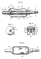
- Figure 1 is a perspective view illustrating the insertable pickup probe and the interface network in accordance with the present invention.
- Figure 2 is a cross-sectional view taken through line 2-2 of the distal inflatable balloon portion of the insertable pickup probe illustrated in Figure 1.
- Figure 3 is an end view as seen from line 3-3 of the insertable pickup probe illustrated in Figure 1.
- Figure 4 is a sectional view taken through line 4-4 of Figure 2.
- Figure 5 is a top sectional view as seen from line 5-5 of Figure 2.
- Figure 6 is a schematic diagram illustrating the receiving coil and interconnecting cable of the insertable pickup probe of the present invention.
- Figure 7 is a schematic diagram illustrating the interconnecting cable and receiving coil fabricated from a single piece of coaxial RF cable in accordance with the present invention.
- Figure 8 is a cross-sectional view illustrating the shaft of the insertable pickup probe illustrated in Figure 1.
- Figure 9 is a schematic diagram illustrating the circuit for performing impedance matching of the probe illustrated in Figure 1 with a remote MRI scanning system.
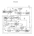
- Figure 10 is a schematic diagram illustrating the circuitry in the interface network for automatically tuning the receiving coil to a specific frequency for a remote MRI scanner.
- Figure 11 is a schematic diagram illustrating the circuitry of the interface network for manually or automatically tuning and impedance matching the receiving coil to a remote MRI scanner.
- Referring first to Figure 1, the insertable prostate pickup probe is shown in an assembled form at 10, which connects to an
interface network 12. The insertableprostate pickup probe 10 is an MRI or NMR receiving device capable of imaging or gathering spectra from the human prostate and surrounding tissue, but may also be used as the transmit coil for RF excitation. Theprobe 10 is used with theinterface network 12 which provides the tuning, impedance matching, and decoupling functions. - The
probe 10 includes ashaft 14 which supports apatient interface balloon 16 at its distal end, ananti-migration disc 18, an introducer 20, and ahandle 22 located at the proximal end of theshaft 14. Aninflater cuff 24 is provided for supplying air to thepatient interface balloon 16 and connects to the proximal end of the shaft by atube 26. Astop cock 28 is provided in thetube 26 for controlling the passage of air through thetube 26 to thepatient interface balloon 16. - As will be described in more detail hereinafter, a receiving coil is contained within the
patient interface balloon 16 and electrically connected to theinterface 12 by an insulatedinterconnecting cable 30 which has aplug 32 at its proximal end for connection toterminal 34 located on the front of theinterface network 12. - The
interface network 12 also includes aterminal 36 for providing a connection to a MRI scanner. Furthermore, theinterface network 12 includes aswitch 38 capable of being moved between an operating position and a tuning position. To display to the operator the mode of operation, indicator lights 40 are provided on the front of theinterface network 12. In addition, a light 42 for indicating the occurrence of a probe failure is provided on the front of theinterface network 12. - Referring now to Figures 2, 4, 5, and 8, the
patient interface balloon 16 of theinsertable pickup probe 10 is illustrated in more detail. Thepatient interface balloon 16 comprises aninner balloon 44 and anouter balloon 46. Theinner balloon 44 is constructed of a flexible medical grade latex or other elastomeric material, which is preferably non-paramagnetic and has low dielectric losses, and is capable of being inflated with air supplied through alumen 48 within theshaft 14, and expelled into theinner balloon 44 via ahole 49 inlumen 48. Theinner balloon 44 is substantially cylindrical in shape except for an anterior flat plane which is covered with anon-stretchable material plane 50, formed of, for example, an adhesive backed cloth material. - A receiving
coil 52 is provided between theinner balloon 44 and theouter balloon 46 and is typically formed of a flexible conductive material. The receivingcoil 52 is arranged between thenon-stretchable plane 50 and theouter balloon 46, is fed to thepatient interface balloon 16 through asecond lumen 54 in theshaft 14, and is fed out of theshaft 14 through ahole 56 in theshaft 14 inside theouter balloon 46. - The
outer balloon 46 has an anterior saddle shape as indicated atreference number 62, for conformably fitting the rectal prostatic bulge inferior to the ampulla of the rectum. In addition, theouter balloon 46 has posterior undulating folds 64 which allow thepatient interface balloon 16 to unfold first when theinner balloon 44 is inflated. This unfolding forces theanterior surface 62 to hug the prostatic region of the rectum, thereby ensuring that the image field of view of theinsertable pickup probe 10 will focus on the desired region of interest. - The
non-stretchable plane 50 serves two functions in thepatient interface balloon 16. First, theplane 50 controls the focus of the inflation stretch of theinner balloon 44; secondly,plane 50 acts as a guide for the receivingcoil 52. Upon inflation, theinner balloon 44 first stretches posteriorly away from the receivingcoil 52. This initiates thefolds 64 of theouter balloon 46 to force posteriorly against the rectum wall until the anatomy offers an equal resistance. Then, thenon-stretchable plane 50 rises and forces the receivingcoil 52 and theanterior surface 62 of theouter balloon 46 against the region of interest. When inflation is complete, the receivingcoil 52 is in position to receive the best possible RF signal from the region of interest. - In addition, as shown in Figure 4,
lateral indentations 74 are provided on theouter balloon 46. Theindentations 74 act as coil positioners when the balloon is in its uninflated state. The receivingcoil 52 is positioned on the shelf formed by theindentations 74 during assembly of the probe. This allows the receivingcoil 52 to be repeatedly positioned relative to the shelf inside theouter balloon 46 for numerous clinical inflation and deflation cycles. - Alternatively, the
patient interface balloon 16 may be constructed with a single ply inflatable balloon of elastomeric material. In this arrangement, the receivingcoil 52 would be bonded to the inside surface of the balloon. - Further yet, the
interface balloon 16 may be constructed with a single multi-ply balloon. This balloon would have the receivingcoil 52 encapsulated between the plies of the elastomeric material. When inflated, the receivingcoil 52 would be forced against the region of interest by the movement of the balloon. The coil encapsulation would take place during the balloon fabrication process by placing the receivingcoil 52 on the surface of the balloon and then redipping the balloon to place another ply of material over the outer surface of the balloon, thus covering the receivingcoil 52. - To assist a clinician in the insertion of the
pickup probe 10, acolored stripe 55 is painted or otherwise marked on theshaft 14. Thestripe 55, best shown in Figure 1, and also shown in Figure 8, may include a scale for indicating the distance which theshaft 14 has been inserted into the patient, and also the radial orientation of theballoon 16 for proper alignment with the prostate. In addition, the distal end 15 (hereinafter referred to as the flexible tip), of theshaft 14 which fits into theballoon 16 is typically more flexible than the remaining length of theshaft 14 to provide a more comfortable fit in the patient and to reduce the possibility of perforating tissue during use. - Referring to Figures 1, 2 and 8, the
shaft 14 is rigid so that when it is twisted radially at thehandle 22, the balloon, shaft, and handle move as a unit to ensure alignment. Theflexible tip 15 is typically made of a more flexible material than theshaft 14, and is bonded to theshaft 14 as indicated atreference numeral 17. Theouter balloon 62 is anchored to theshaft 14 by aproximal clamp 60 and by an interference fit with theflexible tip 15 of theshaft 14. Similarly, theinner balloon 44 is anchored to theshaft 74 by aproximal clamp 58 and by an interference fit with theflexible tip 15. - Figure 3 illustrates the
anti-migration disc 18 in more detail as it fits onto theshaft 14. The disc is is semi-spherical and constructed from semi-rigid plastic. The purpose of theanti-migration disc 18 is to prevent thepickup probe 10 from migrating superiorly due to the normal peristaltic activity of the colon. Thedisc 18 has aslot 19 which snaps onto the shaft, as shown in Figure 3, adjacent the anal sphincter after the device has been operatively placed within the patient. - Turning now to Figures 6 and 7, the connection of the receiving
coil 52 to theinsulated interconnecting cable 30 will be described in more detail. The receivingcoil 52 is a flexible single turn coil capable of picking up radio frequency (RF) signals. In the preferred embodiment, as mentioned previously, theinner balloon 44 of thepatient interface balloon 16 displaces the receivingcoil 52 to the inside of the anterior surface of theouter balloon 46 upon probe inflation. This optimizes the coupling between thecoil 52 and the target anatomy. In order to minimize the dielectric losses in the probe-patient interaction, the receivingcoil 52 is surrounded by aFaraday shield 66 to confine the majority of the coil electrostatic field within a coil-shield gap 68. Since the signal coupling from the NMR proton spin systems to the receivingcoil 52 is achieved exclusively by magnetic means, the presence of theFaraday shield 66 will not detract from the NMR signal, as it is essentially transparent to magnetic field interaction. - The reduction of electrostatic field interaction between the patient and the probe will provide two benefits. First, there will be a reduced electrostatic loss, and thus a greater coil quality factor Q. Second, the effects of the specifics of a particular patient on coil tuning will be reduced due to the containment of the electrostatic field to a defined region. The use of the Faraday shielded coil design will also improve the signal-to-noise ratio performance of the
coil 52 by raising the coil Q. In general, the signal to noise ratio of two geometrically equivalent coils is proportional to the square root of the loaded coil Q, as long as the apparent Q occurs only from the current flowing in the resonant path including the coil conductor. - The receiving
coil 52 of the present invention, in its preferred form, is operated in a series resonant mode, and the interconnectingcable 30 is used as a resonant transformer to convert the probe impedance from a series resonance type to a parallel resonant one as seen at theplug 32 of the interconnectingcable 30. Typically, the interconnectingcable 30 is a coaxial cable. As illustrated in Figure 7, the receivingcoil 52 is resonated by aseries capacitor 70. The length of thecable 30 is one quarter wavelength which allows remote tuning of the receiving coil with one half as much loss in thecable 30 in the series resonant configuration, rather than a parallel resonant configuration, which would employ a one half wavelength cable to connect the coil to theinterface network 12. Use of the one quarter wavelength cable also simplifies the decoupling of the receivingcoil 52, as will be described hereinafter. - As mentioned above, the connection of the
pickup probe 10 to theinterface network 12 is accomplished with a onequarter wavelength cable 30. In the preferred embodiment, the receivingcoil 52 and the conductive portion of thecable 30 are fabricated from a single piece of coaxial RF cable as illustrated in Figure 7. The interconnectingcable 30 serves two system functions. First, in the signal acquisition mode (receive mode), the cable transforms the series resonant coil to appear as a parallel resonant device, according to the well known relationship: Zoutput = (Zcable) (Zcable)/Zinput where Zouput is the probe impedance as seen at theinterface network 12, Zcable is the characteristic impedance of thecable 30 also used to construct thecoil 52, and Zinput is the series resonant impedance of the receivingcoil 52 itself. - As will be described in more detail hereinafter, in the transmitting mode, when the
coil 52 is to be decoupled, Zoutput is the resistance placed in series with the resonant path of the receivingcoil 52 itself. Zcable is the characteristic impedance of the coaxial cable used to construct the receivingcoil 52 andcable 30, and Zinput is the RF resistance of the PIN diode or crossed diodes (illustrated in Figure 9) when forward biased in the transmit mode. - In operation, the
probe 10 is inserted intrarectally while thepatient interface balloon 16 is in the uninflated relaxed state. The providedalignment guide 55 is used to radially and longitudinally position theprobe 10 within or adjacent the region of interest. Thepatient interface balloon 16 is then inflated via theinflator cuff 24 to optimize the tissue to probe interface. Theanti-migration disc 18 is then used to maintain proper positioning of thepickup probe 10 during the clinical scanning procedure. During insertion, theintroducer 20 functions as a dilator for the anal sphincter. The funnel shapedintroducer 20 slides easily over the entire length of theshaft 14. Without the introducer, the anal sphincter would contract around the shaft and interfere with the ability to radially and longitudinally position thepickup probe 10. Thus, theintroducer 20 immediately follows thepatient interface balloon 16 to prevent the anal sphincter from contracting around theshaft 14 of thepickup probe 10. The clinician can then have free movement of theprobe 10 in the rectal cavity. Once theprobe 10 is correctly placed, theintroducer 20 is pulled inferiorly along theshaft 14, allowing the sphincter to contract around theshaft 14. This contraction assists in holding theprobe 10 in place. - Once the
patient interface balloon 16 is inflated, thestop cock 28 is moved to a closed position, thus allowing the clinician to disconnect theinflater cuff 24 without deflating theinterface balloon 16. Theprobe 10 is then connected to theinterface network 12 viaplug 32 of thecable 30. - Referring now to Figures 9-11, the
interface network 12 will be described in detail as it is used with theinsertable pickup probe 10 and a MRI orNMR scanner 73. Theinterface network 10 serves three purposes: tuning of the receivingcoil 52 of theprobe 10 to the Larmour frequency of the MRI orNMR scanner 73; transforming of the output impedance of theprobe 10 to match the scanner input impedance, which is typically 50 ohms; and, decoupling of theprobe 10 during the transmit portion of the scanning sequence. Tuning may be accomplished manually or automatically. In the preferred embodiment, an electronic optimization circuit is provided to automatically adjust the resonance of theprobe 10. - The receiving
coil 52 of theprobe 10 is series resonant and includes a transformer in the form of the onequarter wavelength cable 30 to convert the series resonance to a parallel resonance. The frequency of resonance may be altered by placing an appropriate reactance between thescanner 73 and the interconnectingcable 30, remote from theprobe 10 itself. As such, theprobe 10 may be tuned to thescanner 73 after the probe is inserted into the patient. - As shown in Figure 9, the
interface 12 includes aconventional Pi network 72 consisting of a single series inductor L, and shunting capacitors Ctune and Cmatch, at each end of thenetwork 72. To facilitate tuning of theprobe 10, the input capacitor Ctune of thePi network 72 is made variable as illustrated. Thus, by changing the value of this capacitor, either manually, or automatically by electronically changing the voltage across a varactor diode which may be substituted for the capacitor Ctune, the net reactance appearing across the output of thecable 30 from theprobe 10 is adjusted. Since some of the reactance of the capacitor Ctune is absorbed into thePi network 72, the apparent reactance presented to the probe output can appear resistive, capacitively reactive, or inductively reactive. This allows the probe to be tuned both above and below its natural resonant frequency, while limiting the level of circulating resonance current in the interconnectingcable 30 to the lowest possible value (ideally zero in the case where the natural resonance of the insertable pickup probe matches the Larmour frequency of the MRI or NMR scanner). - For automatic tuning of the
probe 10, the control voltage for the varactor diode substituted for the capacitor Ctune in thePi network 72, is obtained from an electronic tuning circuit described hereinafter. Under manual tuning, the operator simply adjusts the variable capacitor Ctune to reduce the S11 parameter of the receivingcoil 52 as seen at theoutput port 36 of theinterface network 12, to the minimum value. As is well known in the art, the S11 parameter is the scattering parameter of standard RF measurements which indicates the ratio of reflected to incident power at the input port of a network. When the reflected power is 0, representing a voltage standing wave ratio (VSWR) of 1.0:1, the S11 parameter is also 0. When the VSWR is infinite, representing all the incident power being reflected at the input port, the S11 parameter is 1.0. - To match the impedance of the
probe 10 to thescanner 73, transformation of the real part of the output impedance (in the range of 1,000 to 1,500 ohms in the preferred embodiment at 64 MHz) of theprobe 10 is accomplished with thePi network 72 of Figure 9. Any impedance matching network design could be used in place of thePi network 72 illustrated in Figure 9. The values of the various components comprising thePi network 72 are chosen to match the impedances of theprobe 10 andscanner 73. - During the transmitting portion of the scanning procedure, the
probe 10 must be decoupled from theMRI scanner 73 to prevent distortion of the transmitted magnetic field. This is accomplished by the use of an RF switch at theprobe input terminal 34 of theinterface network 12. APIN diode 74 or crossed RF switching diodes can be used at this location, as illustrated in Figure 9, to create a very low impedance at the resonant frequency of theprobe 10 during transmit excitation. Because of the impedance transforming capability provided by the onequarter wavelength cable 32, thePIN diode 74 is forward biased with exceptionally low RF resistance to appear as an open circuit in series with the receivingcoil 52. This limits the RF current flow within the receivingcoil 52 to a very low value, and effectively decouples the receivingcoil 52 from the incident RF magnetic excitation field transmitted into the patient. This arrangement allows thedecoupling diode switch 74 to be located remote from theprobe 10, and can be reused as part of theinterface network 12 after theprobe 10 is disposed. - Referring now to Figure 10, the circuitry for accomplishing the automatic tuning of the receiving
coil 52 of theprobe 10 is generally shown at 76. This circuitry is incorporated within theinterface network 12 and operates by sampling the S11 parameter of theprobe 10 andPi network 72, to generate a control voltage for tuning theprobe 10 with the varactor diode, substituted for Ctune, at theprobe input terminal 34 of theinterface network 12, and a circuit to lock the control voltage at the value which optimizes the S11 parameter. The value of the S11 parameter is determined by using alocal signal source 78 to replace thescanner output terminal 36 on theinterface network 12 during the tuning procedure as accomplished by theswitch 38 of theinterface network 12. Adirectional coupler 80, connected to thelocal signal source 78 obtains a sample of the reflected power from the signal source when using theprobe 10 and theinterface network 12 as a load. This sample is fed to anamplifier 82 and converted to a DC level. The resulting DC signal is then fed into aslope detector 86 of either analog or digital design. - The
slope detector 86, for example, may comprise aRF detector 84 and an analog todigital converter 88 connected to alatch circuit 90 and adigital comparator 92. The analog todigital converter 88 is also connected, together with thelatch circuit 90 and thedigital comparator 92 to asequencer 94. Thedigital comparator 92 provides an output stop command signal to aclock circuit 96 which controls the contents of acounter 98. The value within thecounter 98 determines the value of the control voltage to be applied to the varactor diode which is converted from a digital signal to an analog signal by the digital toanalog converter 100. - In general terms, the
slope detector 86 determines the minimum point of a function, which function in this case is the ratio of reflected to incident power (the S11 parameter). This function monotonically increases in both directions from the minimum point. As the tuning is swept, the function is dropped until a minimum is reached, and then begins to increase again. - The
digital slope detector 86 compares the digitized voltage level of a present data point of the function, with the previous data point. When it is found that the present data point is equal to or greater than the previous point, a level shift from logic 0 tologic 1 is output. The control voltage produced at the output of the digital toanalog converter 100 is ramped from a minimum value towards a maximum value. When the DC level representing the S11 parameter reaches zero slope as it drops from a starting value, the varactor control voltage is locked to the value at that point. - Alternatively, the slope detector may be of an analog design comprising an operational amplifier-differentiator circuit. This circuit takes the first derivative of the voltage level. As the first derivative or slope reverses direction, the operational amplifier output ramps rapidly from its negative rail voltage towards its positive rail voltage. This occurrence can be used as a stop pulse to indicate the minimum.
- The
slope detector circuit 86 can also be used to indicate probe failure. This is accomplished in two ways. First, the tuning of the S11 function never crosses a minimum, or secondly, if the absolute value of the tuning function (S11) becomes greater than a predetermined maximum acceptable value at the minimum. The first condition is an indication of a non- resonant probe, either due to component tolerance, failure, or improper construction. The second condition reveals a probe with an excessively low or high Q, typically indicative of improper construction or faulty materials. - Manual tuning can be accomplished by the circuit illustrated in Figure 11 and generally shown at 102. All of the elements of circuit 102 are similar to that of
circuit 76 with the exception of thedigital voltmeter 104 substituted for theslope detector circuit 86. The reflected power during the tuning procedure is displayed as a scaler quantity on thedigital voltmeter 104 to provide information to the operator relating to the status of the probe tuning. The capacitance of the capacitor Ctune is manually varied during this procedure to minimize the reflected power. - Alternatively, in the event that the probe system requires the ability to automatically control the impedance matching as well as tuning, a second varactor illustrated as Cmatch′ in Figure 11, may be employed as the output capacitor of the
Pi network 72. Adjustment of this reactance in an iterative fashion together with the adjustment of the tuning capacitor Ctune may be accomplished by the automatic tuning circuit illustrated in Figure 10 by toggling the optimization function between the two capacitors. - The
interface network 12 enjoys the benefits of placing all of the decoupling, tuning, and impedance matching hardware remote from theprobe 10 itself to make theprobe 10 compatible with MRI and NMR scanners of different designs by modifying only theinterface network 12 and not theprobe 10. Thus, all systems operating at any specific frequency, such as the various 1.5 Tesla systems, could be accommodated by a single probe type; the variations in the system interface requirements such as the decoupling method (active or passive), connector type, input impedance, and the like could be accommodated by system-specific interface designs. In addition, theinterface network 12 can be designed to be applicable to a family of probes of similar designs. - The above description is intended by way of example only and is not intended to limit the present invention in any way except as set forth in the following claims.
Claims (39)
an elongated shaft member having proximal and distal ends, and having first and second lumens;
an inflatable interface balloon comprised of an inflatable inner balloon and a flexible outer balloon enclosing said inner balloon;
a flexible coil contained within said interface balloon between said inner balloon and said outer balloon;
inflating means connected to said shaft member and connected to said inflatable inner balloon via said first lumen of said shaft member; and
an interconnecting cable connected to said shaft for providing electrical connection to said flexible coil via said second lumen of said shaft member.
an elongated shaft member having proximal and distal ends;
an inflatable interface balloon means positioned proximate the distal end of the shaft member, said inflatable interface balloon being formed of a single multi-ply inflatable balloon;
a flexible antenna coil contained within said inflatable interface balloon means and encapsulated between the plies of said balloon;
inflating means connected to said inflatable interface balloon means for selectively inflating said interface balloon means for intimately placing said flexible antenna coil adjacent said region of interest; and
an interconnecting cable electrically connected to said flexible antenna coil for connecting said flexible coil to a remote scanning device.
an elongated shaft member having proximal and distal ends, and having first and second lumens;
an inflatable interface balloon comprised of an inflatable inner balloon and a flexible outer balloon enclosing said inner balloon, said outer balloon having an anterior saddle shape on one surface thereof and lateral indentations on each side of said outer balloon;
a flexible coil contained within said interface balloon between said inner balloon and said outer balloon and maintained in position in said interface balloon by said lateral indentations of said outer balloon;
inflating means connected to said shaft member and connected to said inflatable inner balloon via said first lumen of said shaft member; and
an interconnecting cable connected to said shaft member for providing electrical connection to said flexible coil via said second lumen of said shaft member.
a series resonant receiving coil;
an interface means for placing said receiving coil intimately adjacent a region of interest of a patient; and
a one quarter wavelength interconnecting cable for connecting said probe to an interface device at its proximal end, said cable causing said receiving coil to appear as a parallel resonant coil at the proximal end of said cable.
an insertable intracavity probe having a receiving coil for placement proximate a region of interest within a cavity of a patient, said receiving coil being a series resonant coil;
a magnetic resonance imaging scanner;
a separable interface network for coupling said probe with said scanner and including impedance matching means to match the output impedance of said probe with the input impedance of the scanner, tuning means to tune the resonant frequency of the probe to the Larmour frequency of the scanner, decoupling means for decoupling the probe from the scanner during a magnetic resonance imaging transmission procedure; and
a one quarter wavelength interconnecting cable for connecting to said receiving coil at its distal end and connecting to said interface network at its proximal end, said one quarter wavelength cable allowing said receiving coil to appear as a parallel resonant coil at said proximal end of said cable.
an input terminal for receiving as input said interconnecting cable of said pickup probe;
an output terminal for connection to said magnetic resonance imaging scanner;
tuning means for tuning said pickup probe to a predetermined scanning frequency of said magnetic resonance imaging scanner;
impedance matching means for matching the output impedance of said pickup probe with the input impedance of said magnetic resonance imaging scanner; and
decoupling means for decoupling said pickup probe from said magnetic resonance imaging scanner during a magnetic resonance imaging transmission event.
a local RF signal generating means selectably coupled to said Pi network and said pickup probe for delivering an electrical signal thereto;
sampling means for sampling the power reflected from the pickup probe and the Pi network;
converting means for converting the sample of the reflected power to a DC signal level;
slope detector means for detecting when said DC signal level reaches a zero slope as it drops from an initial value and adjusting the control voltage of said varactor diode according to the slope of said DC level signal.
tuning means for tuning said pickup probe to a predetermined scanning frequency of said magnetic resonance imaging scanner;
impedance matching means for matching the output impedance of said pickup probe with the input impedance of said magnetic resonance imaging scanner; and
decoupling means for decoupling said pickup probe from said magnetic resonance imaging scanner during a magnetic resonance imaging transmission procedure.
a local RF signal generator selectively coupled to said Pi network and said pickup probe, and for delivering an electrical signal thereto;
sampling means for sampling the power reflected by said Pi network and said pickup probe; and
display means for displaying the power reflected as sampled by said sampling means to allow an operator to adjust the value of said variable capacitor to tune the pickup probe to the Larmour frequency of said magnetic resonance imaging scanner.
an input terminal for receiving as input said interconnecting cable of said pickup probe;
an output terminal for connection to said magnetic resonance imaging scanner; and
impedance matching means for matching the output impedance of said pickup probe with the input impedance of said magnetic resonance imaging scanner, said impedance matching means comprising a Pi network connected in series with said pickup probe and said magnetic resonance imaging scanner and having a series inductor and first and second shunting capacitors, said second capacitor being positioned on the side of said inductor proximate the magnetic resonance imaging scanner and having a predetermined value to cause the Pi network to transform the real part of the output impedance of said pickup probe to match the input impedance of the magnetic resonance imaging scanner.
an input terminal for receiving as input said interconnecting cable of said pickup probe;
an output terminal for connection to said magnetic resonance imaging scanner; and
tuning means for tuning said pickup probe to a predetermined scanning frequency of said magnetic resonance imaging scanner, said tuning means comprising a Pi network connected in series with said pickup probe and said magnetic resonance imaging scanner and having a series inductor and first and second shunting capacitors, said first capacitor being connected to said inductor on the side of said inductor proximate said pickup probe, said first capacitor being variable for adjusting a selected electrical parameter of said pickup probe to tune the resonant frequency of the pickup probe to said predetermined scanning frequency of said magnetic resonance imaging scanner.
an input terminal for receiving as input said interconnecting cable of said pickup probe;
an output terminal for connection to said magnetic resonance imaging scanner;
a Pi network connected in series with said pickup probe and said magnetic resonance imaging scanner and having a series inductor and first and second shunting capacitors; and
decoupling means for decoupling said pickup probe from said magnetic resonance imaging scanner during a magnetic resonance imaging transmission event, said decoupling means comprising a diode connected in parallel with the one quarter wavelength cable from the receiving coil of the pickup probe and the Pi network to the magnetic resonance imaging scanner, said decoupling means forward biasing the diode during a magnetic resonance imaging transmission procedure to create an open circuit in series with the receiving coil of the pickup probe.
an input terminal for receiving as input said interconnecting cable of said pickup probe;
an output terminal for connection to said magnetic resonance imaging scanner; and
tuning means for tuning said pickup probe to a predetermined scanning frequency of said magnetic resonance imaging scanner, said tuning means comprising a Pi network connected in series with said pickup probe and said magnetic resonance imaging scanner and having a series inductor, an input shunting varactor diode adjustable by a control voltage, and an output shunting capacitor, and wherein said interface network further comprises a circuit for automatically adjusting the control voltage of said varactor diode for tuning the resonant frequency of said pickup probe to the said predetermined scanning frequency of said magnetic resonance imaging scanner.
an input terminal for receiving as input said interconnecting cable of said pickup probe;
an output terminal for connection to said magnetic resonance imaging scanner; and
tuning means for tuning said pickup probe to a predetermined scanning frequency of said magnetic resonance imaging scanner, said tuning means comprising a Pi network connected in series with said pickup probe and said magnetic resonance imaging scanner and having a series inductor, an input shunting varactor diode adjustable by a control voltage, and an output shunting capacitor, and wherein said interface network further comprises a circuit for automatically adjusting the control voltage of said varactor diode for tuning the resonant frequency of said pickup probe to the said predetermined scanning frequency of said magnetic resonance imaging scanner, and wherein said circuit for automatically tuning said pickup probe comprises:
a local RF signal generating means selectably coupled to said Pi network and said pickup probe for delivering an electrical signal thereto;
sampling means for sampling the power reflected from the pickup probe and the Pi network;
converting means for converting the sample of the reflected power to a DC signal level; and
slope detector means for detecting when said DC signal level reaches a zero slope as it drops from an initial value and adjusting the control voltage of said varactor diode according to the slope of said DC level signal.
an elongated shaft member having proximal and distal ends, and having at least one lumen;
an inflatable interface balloon comprised of an inflatable inner balloon and a flexible outer balloon enclosing said inner balloon;
a flexible coil contained within said interface balloon between said inner balloon and said outer balloon;
inflating means connected to said shaft member and connected to said inflatable inner balloon via said lumen of said shaft member; and
an interconnecting cable connected to said shaft for providing electrical connection to said flexible coil via said lumen of said shaft member.
an insertable intracavity probe having a receiving coil for placement proximate a region of interest within a cavity of a patient, said intracavity probe being designed as a disposable device;
a magnetic resonance imaging scanner;
a separable interface network for coupling said probe with said scanner and including impedance matching means to match the output impedance of said probe with the input impedance of the scanner, tuning means to tune the resonant frequency of the probe to the Larmour frequency of the scanner, decoupling means for decoupling the probe from the scanner during a magnetic resonance imaging transmission procedure.
an elongated shaft member having proximal and distal ends;
an inflatable interface balloon means;
a flexible coil contained within said interface balloon means;
inflating means connected to said inflatable interface balloon means; and
an interconnecting cable for providing electrical connection to said flexible coil.
an elongated shaft member having proximal and distal ends, and having first and second lumens;
an inflatable interface balloon comprised of an inflatable inner balloon and a flexible outer balloon enclosing said inner balloon;
a flexible coil contained within said interface balloon between said inner balloon and said outer balloon;
inflating means connected to said shaft member and connected to said inflatable inner balloon via said first lumen of said shaft member;
an interconnecting cable connected to said shaft for providing electrical connection to said flexible coil via said second lumen of said shaft member; and
wherein said shaft member includes a positioning scale printed on the outer surface thereof.
an elongated shaft member having proximal and distal ends, and having first and second lumens;
an inflatable interface balloon comprised of an inflatable inner balloon and a flexible outer balloon enclosing said inner balloon;
a flexible coil contained within said interface balloon between said inner balloon and said outer balloon;
inflating means connected to said shaft member and connected to said inflatable inner balloon via said first lumen of said shaft member;
an interconnecting cable connected to said shaft for providing electrical connection to said flexible coil via said second lumen of said shaft member; and
an anti-migration disc, said anti-migration disc having a semi-spherical shape and a slot which snaps into said shaft member for preventing unwanted movement of said probe relative to the cavity of the patient.
an elongated shaft member having proximal and distal ends, and having first and second lumens;
an inflatable interface balloon comprised of an inflatable inner balloon and a flexible outer balloon enclosing said inner balloon;
a flexible coil contained within said interface balloon between said inner balloon and said outer balloon;
inflating means connected to said shaft member and connected to said inflatable inner balloon via said first lumen of said shaft member;
an interconnecting cable connected to said shaft for providing electrical connection to said flexible coil via said second lumen of said shaft member; and
a dilator element slidably mounted on said shaft member for dilating an orifice leading to said cavity to allow easy positioning of the probe within the cavity.
an insertable intracavity probe having a receiving coil for placement proximate a region of interest within a cavity of a patient;
a magnetic resonance imaging scanner;
a separable interface network for coupling said probe with said scanner and including impedance matching means to match the output impedance of said probe with the input impedance of the scanner, tuning means to tune the resonant frequency of the probe to the Larmour frequency of the scanner, decoupling means for decoupling the probe from the scanner during a magnetic resonance imaging transmission procedure.
Priority Applications (1)
| Application Number | Priority Date | Filing Date | Title |
|---|---|---|---|
| EP94120353A EP0659385A1 (en) | 1989-02-27 | 1990-02-26 | Interface network for MRI imaging and spectroscopy |
Applications Claiming Priority (2)
| Application Number | Priority Date | Filing Date | Title |
|---|---|---|---|
| US31587589A | 1989-02-27 | 1989-02-27 | |
| US315875 | 1989-02-27 |
Related Child Applications (1)
| Application Number | Title | Priority Date | Filing Date |
|---|---|---|---|
| EP94120353.1 Division-Into | 1990-02-26 |
Publications (2)
| Publication Number | Publication Date |
|---|---|
| EP0385367A1 true EP0385367A1 (en) | 1990-09-05 |
| EP0385367B1 EP0385367B1 (en) | 1995-10-25 |
Family
ID=23226439
Family Applications (2)
| Application Number | Title | Priority Date | Filing Date |
|---|---|---|---|
| EP90103732A Expired - Lifetime EP0385367B1 (en) | 1989-02-27 | 1990-02-26 | Intracavity probe and interface device for MRI imaging and spectroscopy |
| EP94120353A Withdrawn EP0659385A1 (en) | 1989-02-27 | 1990-02-26 | Interface network for MRI imaging and spectroscopy |
Family Applications After (1)
| Application Number | Title | Priority Date | Filing Date |
|---|---|---|---|
| EP94120353A Withdrawn EP0659385A1 (en) | 1989-02-27 | 1990-02-26 | Interface network for MRI imaging and spectroscopy |
Country Status (6)
| Country | Link |
|---|---|
| US (1) | US5355087A (en) |
| EP (2) | EP0385367B1 (en) |
| JP (1) | JPH02277440A (en) |
| AT (1) | ATE129395T1 (en) |
| CA (1) | CA2010899A1 (en) |
| DE (2) | DE69023153T2 (en) |
Cited By (24)
| Publication number | Priority date | Publication date | Assignee | Title |
|---|---|---|---|---|
| WO1993005706A1 (en) * | 1991-09-17 | 1993-04-01 | Medrad, Inc. | Externally moveable intracavity probe for mri imaging and spectroscopy |
| NL9201724A (en) * | 1991-10-07 | 1993-05-03 | Medrad Inc En The Trustees Of | PROBE FOR MRI IMAGING AND SPECTROSCOPY, ESPECIALLY IN THE CERVICAL AREA. |
| US5271400A (en) * | 1992-04-01 | 1993-12-21 | General Electric Company | Tracking system to monitor the position and orientation of a device using magnetic resonance detection of a sample contained within the device |
| EP0576016A1 (en) * | 1992-06-25 | 1993-12-29 | Olympus Optical Co., Ltd. | Diagnostic system using nuclear magnetic resonance phenomenon |
| US5303707A (en) * | 1991-11-08 | 1994-04-19 | Picker International, Ltd. | Magnetic resonance methods and apparatus |
| US5307808A (en) * | 1992-04-01 | 1994-05-03 | General Electric Company | Tracking system and pulse sequences to monitor the position of a device using magnetic resonance |
| EP0597546A1 (en) * | 1992-11-10 | 1994-05-18 | Dräger Medical Electronics B.V. | Invasive MRI transducers |
| US5318025A (en) * | 1992-04-01 | 1994-06-07 | General Electric Company | Tracking system to monitor the position and orientation of a device using multiplexed magnetic resonance detection |
| WO1994012102A1 (en) * | 1992-11-25 | 1994-06-09 | Medrad, Inc. | Endorectal probe with planar movable mri coil |
| US5353795A (en) * | 1992-12-10 | 1994-10-11 | General Electric Company | Tracking system to monitor the position of a device using multiplexed magnetic resonance detection |
| US5400787A (en) * | 1993-11-24 | 1995-03-28 | Magna-Lab, Inc. | Inflatable magnetic resonance imaging sensing coil assembly positioning and retaining device and method for using the same |
| US5447156A (en) * | 1994-04-04 | 1995-09-05 | General Electric Company | Magnetic resonance (MR) active invasive devices for the generation of selective MR angiograms |
| FR2723537A1 (en) * | 1994-08-10 | 1996-02-16 | Cordis Sa | Balloon-tipped catheter, prepd. using silicone soln. |
| NL1004381C2 (en) * | 1996-10-30 | 1998-05-08 | Cordis Europ | Balloon-type catheter |
| EP0850595A1 (en) * | 1996-12-16 | 1998-07-01 | Gec-Marconi Limited | Nuclear magnetic resonance imaging apparatus |
| US5792055A (en) * | 1994-03-18 | 1998-08-11 | Schneider (Usa) Inc. | Guidewire antenna |
| EP1021730B1 (en) * | 1997-10-13 | 2003-04-02 | Simag GmbH | MR imaging system and vena cava filter therefor |
| WO2006043272A2 (en) * | 2004-10-18 | 2006-04-27 | Topspin Medical (Israel) Ltd. | Expanding imaging probe |
| WO2007138547A3 (en) * | 2006-05-30 | 2008-05-02 | Philips Intellectual Property | Detuning a radio-frequency coil |
| USRE40587E1 (en) | 1994-03-18 | 2008-11-25 | Schneider (Europe) A.G. | Antenna for magnetic resonance imaging and method of use |
| US7496397B2 (en) | 2004-05-06 | 2009-02-24 | Boston Scientific Scimed, Inc. | Intravascular antenna |
| US8581590B2 (en) | 2008-11-12 | 2013-11-12 | Medrad, Inc. | Quadrature endorectal coils and interface devices therefor |
| US9817090B2 (en) | 2010-07-01 | 2017-11-14 | Bayer Healthcare Llc | Multi-channel endorectal coils and interface devices therefor |
| US10030961B2 (en) | 2015-11-27 | 2018-07-24 | General Electric Company | Gap measuring device |
Families Citing this family (84)
| Publication number | Priority date | Publication date | Assignee | Title |
|---|---|---|---|---|
| US5427103A (en) * | 1992-06-29 | 1995-06-27 | Olympus Optical Co., Ltd. | MRI apparatus for receiving nuclear-magnetic resonance signals of a living body |
| US5483158A (en) * | 1993-10-21 | 1996-01-09 | The Regents Of The University Of California | Method and apparatus for tuning MRI RF coils |
| US5699801A (en) * | 1995-06-01 | 1997-12-23 | The Johns Hopkins University | Method of internal magnetic resonance imaging and spectroscopic analysis and associated apparatus |
| US6898454B2 (en) | 1996-04-25 | 2005-05-24 | The Johns Hopkins University | Systems and methods for evaluating the urethra and the periurethral tissues |
| US6549800B1 (en) | 1996-04-25 | 2003-04-15 | Johns Hopkins Unversity School Of Medicine | Methods for in vivo magnetic resonance imaging |
| US6628980B2 (en) | 2000-03-24 | 2003-09-30 | Surgi-Vision, Inc. | Apparatus, systems, and methods for in vivo magnetic resonance imaging |
| US6263229B1 (en) | 1998-11-13 | 2001-07-17 | Johns Hopkins University School Of Medicine | Miniature magnetic resonance catheter coils and related methods |
| US7236816B2 (en) * | 1996-04-25 | 2007-06-26 | Johns Hopkins University | Biopsy and sampling needle antennas for magnetic resonance imaging-guided biopsies |
| US6675033B1 (en) | 1999-04-15 | 2004-01-06 | Johns Hopkins University School Of Medicine | Magnetic resonance imaging guidewire probe |
| US6051974A (en) * | 1997-11-26 | 2000-04-18 | Picker International, Inc. | MRI endocavitary coils and decontamination |
| US6408202B1 (en) | 1998-11-03 | 2002-06-18 | The Johns Hopkins University | Transesophageal magnetic resonance analysis method and apparatus |
| EP1126783A4 (en) * | 1998-11-03 | 2006-03-22 | Univ Johns Hopkins Med | Transesophageal magnetic resonance analysis method and apparatus |
| US8244370B2 (en) | 2001-04-13 | 2012-08-14 | Greatbatch Ltd. | Band stop filter employing a capacitor and an inductor tank circuit to enhance MRI compatibility of active medical devices |
| US6701176B1 (en) | 1998-11-04 | 2004-03-02 | Johns Hopkins University School Of Medicine | Magnetic-resonance-guided imaging, electrophysiology, and ablation |
| US6344745B1 (en) | 1998-11-25 | 2002-02-05 | Medrad, Inc. | Tapered birdcage resonator for improved homogeneity in MRI |
| US6356081B1 (en) | 1998-11-25 | 2002-03-12 | Medrad, Inc. | Multimode operation of quadrature phased array MR coil systems |
| US6798206B2 (en) | 1998-11-25 | 2004-09-28 | Medrad, Inc. | Neurovascular coil system and interface and system therefor and method of operating same in a multitude of modes |
| NL1011364C2 (en) * | 1999-02-22 | 2000-08-24 | Cordis Europ | Catheter with circuit for positioning and imaging. |
| US7848788B2 (en) | 1999-04-15 | 2010-12-07 | The Johns Hopkins University | Magnetic resonance imaging probe |
| US6512374B1 (en) | 1999-04-26 | 2003-01-28 | Medrad, Inc. | MR local imaging coil operable as a receive only or a transmit/receive coil |
| WO2001056469A2 (en) | 2000-02-01 | 2001-08-09 | Surgi-Vision, Inc. | Magnetic resonance imaging transseptal needle antenna |
| US20030158475A1 (en) * | 2000-03-30 | 2003-08-21 | Johnson Vicki Young | Intravaginal radiofrequency imaging device |
| US6526306B2 (en) | 2000-03-30 | 2003-02-25 | Uab Research Foundation | Intravaginal radiofrequency imaging device |
| JP2004504076A (en) * | 2000-03-31 | 2004-02-12 | サージ−ビジョン インク | System and method for assessing urethra and periurethral tissue |
| US8909325B2 (en) | 2000-08-21 | 2014-12-09 | Biosensors International Group, Ltd. | Radioactive emission detector equipped with a position tracking system and utilization thereof with medical systems and in medical procedures |
| US8489176B1 (en) | 2000-08-21 | 2013-07-16 | Spectrum Dynamics Llc | Radioactive emission detector equipped with a position tracking system and utilization thereof with medical systems and in medical procedures |
| US8565860B2 (en) | 2000-08-21 | 2013-10-22 | Biosensors International Group, Ltd. | Radioactive emission detector equipped with a position tracking system |
| KR20010000425A (en) * | 2000-09-28 | 2001-01-05 | 김대진 | RF variable filter circuit in MRI Modem by tracking filter |
| US6501980B1 (en) | 2000-11-09 | 2002-12-31 | Koninklijke Philips Electronics N.V. | Easily decontaminated MRI endocavity coils |
| US8219208B2 (en) | 2001-04-13 | 2012-07-10 | Greatbatch Ltd. | Frequency selective passive component networks for active implantable medical devices utilizing an energy dissipating surface |
| US20070088416A1 (en) | 2001-04-13 | 2007-04-19 | Surgi-Vision, Inc. | Mri compatible medical leads |
| US6832108B2 (en) | 2001-04-19 | 2004-12-14 | Koninklijke Philips Electronics, N.V. | Endovaginal MRI receiver coil |
| DE10138705C1 (en) * | 2001-08-07 | 2003-03-27 | Siemens Ag | Method for homogenizing the image recording of a magnetic resonance measurement |
| US20030173966A1 (en) * | 2002-03-14 | 2003-09-18 | Thr Board Of Trustees Of The Leland Stanford Junior University | Varactor tuned flexible interventional receiver coils |
| CN1802123B (en) * | 2002-05-16 | 2010-04-28 | 梅德拉股份有限公司 | System of obtaining images and spectra of intracavity structures using 3.0 tesla magnetic resonance systems |
| JP4437073B2 (en) * | 2002-05-16 | 2010-03-24 | メドラッド インコーポレーテッド | System and method for obtaining images and spectra of intracavitary structures using a 3.0 Tesla magnetic resonance system |
| US6904307B2 (en) | 2002-05-29 | 2005-06-07 | Surgi-Vision, Inc. | Magnetic resonance probes |
| US20040230114A1 (en) * | 2003-03-18 | 2004-11-18 | Clatterbaugh Guy V. | MRI flex circuit catheter imaging coil |
| US7968851B2 (en) | 2004-01-13 | 2011-06-28 | Spectrum Dynamics Llc | Dynamic spect camera |
| WO2005067383A2 (en) | 2004-01-13 | 2005-07-28 | Spectrum Dynamics Llc | Multi-dimensional image reconstruction |
| US8586932B2 (en) | 2004-11-09 | 2013-11-19 | Spectrum Dynamics Llc | System and method for radioactive emission measurement |
| US8571881B2 (en) | 2004-11-09 | 2013-10-29 | Spectrum Dynamics, Llc | Radiopharmaceutical dispensing, administration, and imaging |
| WO2008010227A2 (en) | 2006-07-19 | 2008-01-24 | Spectrum Dynamics Llc | Imaging protocols |
| US9470801B2 (en) | 2004-01-13 | 2016-10-18 | Spectrum Dynamics Llc | Gating with anatomically varying durations |
| EP1743186B1 (en) * | 2004-04-23 | 2017-07-26 | Koninklijke Philips N.V. | Magnetic resonance imaging system provided with an electrical accessory device |
| EP1778957A4 (en) | 2004-06-01 | 2015-12-23 | Biosensors Int Group Ltd | Radioactive-emission-measurement optimization to specific body structures |
| US8615405B2 (en) | 2004-11-09 | 2013-12-24 | Biosensors International Group, Ltd. | Imaging system customization using data from radiopharmaceutical-associated data carrier |
| US8423125B2 (en) | 2004-11-09 | 2013-04-16 | Spectrum Dynamics Llc | Radioimaging |
| EP1827505A4 (en) | 2004-11-09 | 2017-07-12 | Biosensors International Group, Ltd. | Radioimaging |
| US9943274B2 (en) | 2004-11-09 | 2018-04-17 | Spectrum Dynamics Medical Limited | Radioimaging using low dose isotope |
| US9316743B2 (en) | 2004-11-09 | 2016-04-19 | Biosensors International Group, Ltd. | System and method for radioactive emission measurement |
| JP4848377B2 (en) * | 2004-11-15 | 2011-12-28 | メドラッド インコーポレーテッド | Intracavity probe and its interface used to obtain images and spectra of intraluminal structures using a high-region magnetic resonance system |
| US8644910B2 (en) | 2005-07-19 | 2014-02-04 | Biosensors International Group, Ltd. | Imaging protocols |
| US8837793B2 (en) | 2005-07-19 | 2014-09-16 | Biosensors International Group, Ltd. | Reconstruction stabilizer and active vision |
| US8894974B2 (en) | 2006-05-11 | 2014-11-25 | Spectrum Dynamics Llc | Radiopharmaceuticals for diagnosis and therapy |
| US8610075B2 (en) | 2006-11-13 | 2013-12-17 | Biosensors International Group Ltd. | Radioimaging applications of and novel formulations of teboroxime |
| WO2008075362A2 (en) | 2006-12-20 | 2008-06-26 | Spectrum Dynamics Llc | A method, a system, and an apparatus for using and processing multidimensional data |
| US9707379B2 (en) | 2007-01-16 | 2017-07-18 | Radiadyne Llc | Rectal balloon with locking stopper |
| US20080172080A1 (en) * | 2007-01-16 | 2008-07-17 | Isham John | Minimally invasive rectal balloon apparatus |
| US9381334B2 (en) | 2007-01-16 | 2016-07-05 | Radiadyne Llc | Endorectal balloon with gas release lumen |
| US20080300619A1 (en) * | 2007-01-16 | 2008-12-04 | Isham John | Rectal balloon apparatus with radiation sensor and/or markers |
| US8500771B2 (en) | 2007-01-16 | 2013-08-06 | Radiadyne, Llc | Rectal balloon apparatus with pressure relieving lumen and sensors |
| US7976497B2 (en) | 2007-09-25 | 2011-07-12 | Polyzen Inc. | Multi-layer film welded articulated balloon |
| US8521253B2 (en) | 2007-10-29 | 2013-08-27 | Spectrum Dynamics Llc | Prostate imaging |
| US9439735B2 (en) | 2009-06-08 | 2016-09-13 | MRI Interventions, Inc. | MRI-guided interventional systems that can track and generate dynamic visualizations of flexible intrabody devices in near real time |
| US8396532B2 (en) | 2009-06-16 | 2013-03-12 | MRI Interventions, Inc. | MRI-guided devices and MRI-guided interventional systems that can track and generate dynamic visualizations of the devices in near real time |
| US8338788B2 (en) | 2009-07-29 | 2012-12-25 | Spectrum Dynamics Llc | Method and system of optimized volumetric imaging |
| US8610435B2 (en) * | 2009-11-24 | 2013-12-17 | Medrad, Inc. | Focus coil array and interface devices therefor |
| CN103209735B (en) | 2010-06-10 | 2016-04-13 | 美瑞德医疗有限责任公司 | Intracavity balloon catheter |
| CN102841326A (en) * | 2011-06-21 | 2012-12-26 | 陆建平 | Small-size radio frequency coil for experimental animal pancreas |
| US10172521B2 (en) | 2013-07-08 | 2019-01-08 | General Electric Company | Systems and methods for tracking imaging attenuators |
| US20160302880A1 (en) * | 2013-12-10 | 2016-10-20 | Koninklijke Philips N.V. | Magetic resonance coil assembly for fiducial markers |
| EP3042687B1 (en) | 2015-01-08 | 2020-10-14 | Myriad Medical LLC | Intracavity balloon catheter |
| US10386430B2 (en) * | 2016-09-21 | 2019-08-20 | Quality Electrodynamics, Llc | Single layer magnetic resonance imaging transmit/receive radio frequency coil |
| US10852373B2 (en) | 2016-09-21 | 2020-12-01 | Quality Electrodynamics, Llc | Modulating magnetic resonance imaging transmit field in magnetic resonance fingerprinting using single layer transmit/receive radio frequency coil |
| US11243280B2 (en) * | 2017-02-20 | 2022-02-08 | University Of Florida Research Foundation, Inc. | Augmented tune/match circuits for high performance dual nuclear transmission line resonators |
| US11156682B2 (en) | 2017-03-24 | 2021-10-26 | Quality Electrodynamics, Llc | Single layer magnetic resonance imaging transmit/receive radio frequency coil for different anatomies |
| US10976388B2 (en) | 2017-03-24 | 2021-04-13 | Quality Electrodynamics, Llc | Minimizing intravascular magnetic resonance imaging (MRI) guidewire heating with single layer MRI transmit/receive radio frequency coil |
| US10649048B2 (en) | 2017-04-28 | 2020-05-12 | Quality Electrodynamics, Llc | Single layer magnetic resonance imaging (MRI) transmit/receive (TX/RX) radio frequency (RF) coil with integrated shimming |
| US11193992B2 (en) | 2017-05-05 | 2021-12-07 | Quality Electrodynamics, Llc | Single layer magnetic resonance imaging (MRI) transmit/receive (Tx/Rx) radio frequency (RF) coil with induced current failsafe protection |
| US10838028B2 (en) | 2017-06-19 | 2020-11-17 | Quality Electrodynamics, Llc | Decoupling magnetic resonance imaging (MRI) radio frequency (RF) coil elements with high acceleration factor in parallel transmit (pTx) or receive (Rx) coils using fewer channels |
| GB2568245A (en) * | 2017-11-07 | 2019-05-15 | Elekta ltd | Shielding of magnetic resonance imaging apparatus |
| CN114252823A (en) * | 2020-09-23 | 2022-03-29 | 西门子(深圳)磁共振有限公司 | Coil assembly, magnetic resonance imaging system and use method of coil assembly |
| WO2023082038A1 (en) * | 2021-11-09 | 2023-05-19 | 深圳先进技术研究院 | Magnetic resonance coil |
Citations (7)
| Publication number | Priority date | Publication date | Assignee | Title |
|---|---|---|---|---|
| WO1984001513A1 (en) * | 1982-10-08 | 1984-04-26 | David Hardcastle | Balloon catheter and process for the manufacture thereof |
| EP0149338A2 (en) * | 1984-01-16 | 1985-07-24 | General Motors Corporation | Windshield wiper transmission |
| DE3421830A1 (en) * | 1984-06-13 | 1985-12-19 | Philips Patentverwaltung Gmbh, 2000 Hamburg | NUCLEAR SPIN RESONANCE DEVICE WITH AN ACTUATOR FOR ADAPTING OR RE-TUNING THE RESONATOR |
| WO1986001093A1 (en) * | 1984-08-13 | 1986-02-27 | Howard Roy Berke | Solid state nmr probe |
| EP0214721A1 (en) * | 1985-07-05 | 1987-03-18 | Franklin Medical Limited | Balloon catheters |
| WO1988000071A1 (en) * | 1986-06-26 | 1988-01-14 | Tassilo Bonzel | Dilatation catheter with expanding balloon |
| EP0299158A1 (en) * | 1987-06-15 | 1989-01-18 | Boston Scientific Corporation | Multi-lumen balloon catheter |
Family Cites Families (17)
| Publication number | Priority date | Publication date | Assignee | Title |
|---|---|---|---|---|
| US3800802A (en) * | 1972-01-07 | 1974-04-02 | Int Medical Electronics Ltd | Short-wave therapy apparatus |
| US4633181A (en) * | 1983-08-11 | 1986-12-30 | Regents Of The University Of Calif. | Apparatus and method for increasing the sensitivity of a nuclear magnetic resonance probe |
| FI73320C (en) * | 1984-01-20 | 1987-09-10 | Instrumentarium Oy | NMR SPOLARRANGEMANG. |
| DE3429386A1 (en) * | 1984-08-09 | 1986-02-27 | Siemens AG, 1000 Berlin und 8000 München | MAIN SPIN TOMOGRAPHY UNIT |
| US4672972A (en) * | 1984-08-13 | 1987-06-16 | Berke Howard R | Solid state NMR probe |
| JPS6190525A (en) * | 1984-10-11 | 1986-05-08 | Mitsubishi Electric Corp | Transmitter of nuclear magnetic resonance imaging system |
| JPS61288848A (en) * | 1985-06-17 | 1986-12-19 | 株式会社日立製作所 | Probe for nmr imaging apparatus |
| US4764726A (en) * | 1985-08-05 | 1988-08-16 | Picker International, Inc. | Low distortion RF switching circuit without DC bias |
| US4920318A (en) * | 1985-08-14 | 1990-04-24 | Picker International, Inc. | Surface coil system for magnetic resonance imaging |
| US4793356A (en) * | 1985-08-14 | 1988-12-27 | Picker International, Inc. | Surface coil system for magnetic resonance imaging |
| JPS62286451A (en) * | 1986-06-05 | 1987-12-12 | 三菱電機株式会社 | Magnetic resonance receiving probe |
| EP0249338A3 (en) * | 1986-06-12 | 1988-12-14 | C.R. Bard, Inc. | Retroperfusion catheter |
| EP0256370A1 (en) * | 1986-08-12 | 1988-02-24 | Siemens Aktiengesellschaft | Antenna arrangement for exciting and recording nuclear magnetic resonance |
| JP2565911B2 (en) * | 1987-07-15 | 1996-12-18 | オリンパス光学工業株式会社 | NMR measurement endoscope system |
| US4960106A (en) * | 1987-04-28 | 1990-10-02 | Olympus Optical Co., Ltd. | Endoscope apparatus |
| JPS63270036A (en) * | 1987-04-30 | 1988-11-08 | Toshiba Corp | Magnetic resonance imaging apparatus |
| US4855680A (en) * | 1987-11-02 | 1989-08-08 | The Regents Of The University Of California | Enhanced decoupling of MRI RF coil pairs during RF tuning of MRI RF transmit coil |
-
1990
- 1990-02-26 EP EP90103732A patent/EP0385367B1/en not_active Expired - Lifetime
- 1990-02-26 CA CA002010899A patent/CA2010899A1/en not_active Abandoned
- 1990-02-26 AT AT90103732T patent/ATE129395T1/en active
- 1990-02-26 EP EP94120353A patent/EP0659385A1/en not_active Withdrawn
- 1990-02-26 DE DE69023153T patent/DE69023153T2/en not_active Expired - Lifetime
- 1990-02-26 DE DE0385367T patent/DE385367T1/en active Pending
- 1990-02-27 JP JP2047101A patent/JPH02277440A/en active Granted
-
1991
- 1991-02-11 US US07/637,658 patent/US5355087A/en not_active Expired - Lifetime
Patent Citations (7)
| Publication number | Priority date | Publication date | Assignee | Title |
|---|---|---|---|---|
| WO1984001513A1 (en) * | 1982-10-08 | 1984-04-26 | David Hardcastle | Balloon catheter and process for the manufacture thereof |
| EP0149338A2 (en) * | 1984-01-16 | 1985-07-24 | General Motors Corporation | Windshield wiper transmission |
| DE3421830A1 (en) * | 1984-06-13 | 1985-12-19 | Philips Patentverwaltung Gmbh, 2000 Hamburg | NUCLEAR SPIN RESONANCE DEVICE WITH AN ACTUATOR FOR ADAPTING OR RE-TUNING THE RESONATOR |
| WO1986001093A1 (en) * | 1984-08-13 | 1986-02-27 | Howard Roy Berke | Solid state nmr probe |
| EP0214721A1 (en) * | 1985-07-05 | 1987-03-18 | Franklin Medical Limited | Balloon catheters |
| WO1988000071A1 (en) * | 1986-06-26 | 1988-01-14 | Tassilo Bonzel | Dilatation catheter with expanding balloon |
| EP0299158A1 (en) * | 1987-06-15 | 1989-01-18 | Boston Scientific Corporation | Multi-lumen balloon catheter |
Cited By (40)
| Publication number | Priority date | Publication date | Assignee | Title |
|---|---|---|---|---|
| EP0848931A3 (en) * | 1991-09-17 | 1998-10-21 | Medrad Inc. | Externally moveable intracavity probe for MRI imaging and spectroscopy |
| WO1993005706A1 (en) * | 1991-09-17 | 1993-04-01 | Medrad, Inc. | Externally moveable intracavity probe for mri imaging and spectroscopy |
| EP0848931A2 (en) * | 1991-09-17 | 1998-06-24 | Medrad Inc. | Externally moveable intracavity probe for MRI imaging and spectroscopy |
| US5307814A (en) * | 1991-09-17 | 1994-05-03 | Medrad, Inc. | Externally moveable intracavity probe for MRI imaging and spectroscopy |
| NL9201724A (en) * | 1991-10-07 | 1993-05-03 | Medrad Inc En The Trustees Of | PROBE FOR MRI IMAGING AND SPECTROSCOPY, ESPECIALLY IN THE CERVICAL AREA. |
| US5451232A (en) * | 1991-10-07 | 1995-09-19 | Medrad, Inc. | Probe for MRI imaging and spectroscopy particularly in the cervical region |
| US5303707A (en) * | 1991-11-08 | 1994-04-19 | Picker International, Ltd. | Magnetic resonance methods and apparatus |
| US5318025A (en) * | 1992-04-01 | 1994-06-07 | General Electric Company | Tracking system to monitor the position and orientation of a device using multiplexed magnetic resonance detection |
| US5307808A (en) * | 1992-04-01 | 1994-05-03 | General Electric Company | Tracking system and pulse sequences to monitor the position of a device using magnetic resonance |
| US5271400A (en) * | 1992-04-01 | 1993-12-21 | General Electric Company | Tracking system to monitor the position and orientation of a device using magnetic resonance detection of a sample contained within the device |
| US5402788A (en) * | 1992-06-25 | 1995-04-04 | Olympus Optical Co., Ltd. | Diagnostic system using nuclear magnetic resonance phenomenon |
| EP0766093A1 (en) * | 1992-06-25 | 1997-04-02 | Olympus Optical Co., Ltd. | Diagnostic system |
| EP0576016A1 (en) * | 1992-06-25 | 1993-12-29 | Olympus Optical Co., Ltd. | Diagnostic system using nuclear magnetic resonance phenomenon |
| EP0597546A1 (en) * | 1992-11-10 | 1994-05-18 | Dräger Medical Electronics B.V. | Invasive MRI transducers |
| US5413104A (en) * | 1992-11-10 | 1995-05-09 | Drager Medical Electronics B.V. | Invasive MRI transducers |
| WO1994012102A1 (en) * | 1992-11-25 | 1994-06-09 | Medrad, Inc. | Endorectal probe with planar movable mri coil |
| US5365928A (en) * | 1992-11-25 | 1994-11-22 | Medrad, Inc. | Endorectal probe with planar moveable MRI coil |
| US5353795A (en) * | 1992-12-10 | 1994-10-11 | General Electric Company | Tracking system to monitor the position of a device using multiplexed magnetic resonance detection |
| US5400787A (en) * | 1993-11-24 | 1995-03-28 | Magna-Lab, Inc. | Inflatable magnetic resonance imaging sensing coil assembly positioning and retaining device and method for using the same |
| WO1995014428A1 (en) * | 1993-11-24 | 1995-06-01 | Magna-Lab Inc. | Inflatable magnetic resonance imaging sensing coil device |
| USRE40587E1 (en) | 1994-03-18 | 2008-11-25 | Schneider (Europe) A.G. | Antenna for magnetic resonance imaging and method of use |
| US5792055A (en) * | 1994-03-18 | 1998-08-11 | Schneider (Usa) Inc. | Guidewire antenna |
| US5447156A (en) * | 1994-04-04 | 1995-09-05 | General Electric Company | Magnetic resonance (MR) active invasive devices for the generation of selective MR angiograms |
| FR2723537A1 (en) * | 1994-08-10 | 1996-02-16 | Cordis Sa | Balloon-tipped catheter, prepd. using silicone soln. |
| NL1004381C2 (en) * | 1996-10-30 | 1998-05-08 | Cordis Europ | Balloon-type catheter |
| EP0850595A1 (en) * | 1996-12-16 | 1998-07-01 | Gec-Marconi Limited | Nuclear magnetic resonance imaging apparatus |
| US5876338A (en) * | 1996-12-16 | 1999-03-02 | Picker International, Inc. | Nuclear magnetic resonance imaging apparatus |
| EP1021730B1 (en) * | 1997-10-13 | 2003-04-02 | Simag GmbH | MR imaging system and vena cava filter therefor |
| US6847837B1 (en) | 1997-10-13 | 2005-01-25 | Simag Gmbh | MR imaging method and medical device for use in method |
| US8116846B2 (en) | 2004-05-06 | 2012-02-14 | Boston Scientific Scimed, Inc. | Intravascular antenna |
| US7496397B2 (en) | 2004-05-06 | 2009-02-24 | Boston Scientific Scimed, Inc. | Intravascular antenna |
| WO2006043272A3 (en) * | 2004-10-18 | 2006-09-14 | Topspin Medical Israel Ltd | Expanding imaging probe |
| WO2006043272A2 (en) * | 2004-10-18 | 2006-04-27 | Topspin Medical (Israel) Ltd. | Expanding imaging probe |
| WO2007138547A3 (en) * | 2006-05-30 | 2008-05-02 | Philips Intellectual Property | Detuning a radio-frequency coil |
| US7973531B2 (en) | 2006-05-30 | 2011-07-05 | Koninklijke Philips Electronics N.V. | Detuning a radio-frequency coil |
| CN101454685B (en) * | 2006-05-30 | 2012-09-05 | 皇家飞利浦电子股份有限公司 | Detuning a radio-frequency coil |
| US8581590B2 (en) | 2008-11-12 | 2013-11-12 | Medrad, Inc. | Quadrature endorectal coils and interface devices therefor |
| US9817090B2 (en) | 2010-07-01 | 2017-11-14 | Bayer Healthcare Llc | Multi-channel endorectal coils and interface devices therefor |
| US10197645B2 (en) | 2010-07-01 | 2019-02-05 | Bayer Healthcare Llc | Multi-channel endorectal coils and interface devices therefor |
| US10030961B2 (en) | 2015-11-27 | 2018-07-24 | General Electric Company | Gap measuring device |
Also Published As
| Publication number | Publication date |
|---|---|
| DE69023153T2 (en) | 1996-04-18 |
| DE385367T1 (en) | 1995-06-29 |
| DE69023153D1 (en) | 1995-11-30 |
| EP0385367B1 (en) | 1995-10-25 |
| ATE129395T1 (en) | 1995-11-15 |
| CA2010899A1 (en) | 1990-08-27 |
| EP0659385A1 (en) | 1995-06-28 |
| JPH02277440A (en) | 1990-11-14 |
| JPH0558731B2 (en) | 1993-08-27 |
| US5355087A (en) | 1994-10-11 |
Similar Documents
| Publication | Publication Date | Title |
|---|---|---|
| EP0385367B1 (en) | Intracavity probe and interface device for MRI imaging and spectroscopy | |
| US5476095A (en) | Intracavity probe and interface device for MRI imaging and spectroscopy | |
| EP1811898B1 (en) | Intracavity probes and interfaces therefor for use in obtaining images and spectra of intracavity structures using high field magnetic resonance systems | |
| US8989841B2 (en) | Interface devices for use with intracavity probes for high field strength magnetic resonance systems | |
| CA2078536C (en) | Externally moveable intracavity probe for mri imaging and spectroscopy | |
| US5050607A (en) | High resolution magnetic resonance imaging of body cavities | |
| CA2079974C (en) | Probe for mri imaging and spectroscopy particularly in the cervical region | |
| US9817090B2 (en) | Multi-channel endorectal coils and interface devices therefor | |
| CN1802123B (en) | System of obtaining images and spectra of intracavity structures using 3.0 tesla magnetic resonance systems | |
| Timilsina et al. | A novel expandable catheter wireless amplified NMR detector for MR sensitivity accessing the kidney in rodent model | |
| EP0841575A2 (en) | Magnetic resonance imaging | |
| WO2019091872A1 (en) | Disposable prostate coil for mri with hybrid quarter wave transformer detune circuit and wireless power | |
| JPH11225986A (en) | Mri endoscope and rf coil for mri | |
| Vlachos et al. | Automatic Deactivation in Phased Array Probe for Human Prostate Magnetic Resonance Imaging at 1.5 T |
Legal Events
| Date | Code | Title | Description |
|---|---|---|---|
| PUAI | Public reference made under article 153(3) epc to a published international application that has entered the european phase |
Free format text: ORIGINAL CODE: 0009012 |
|
| AK | Designated contracting states |
Kind code of ref document: A1 Designated state(s): AT BE CH DE DK ES FR GB GR IT LI LU NL SE |
|
| 17P | Request for examination filed |
Effective date: 19901206 |
|
| 17Q | First examination report despatched |
Effective date: 19930322 |
|
| TCNL | Nl: translation of patent claims filed | ||
| DET | De: translation of patent claims | ||
| GRAA | (expected) grant |
Free format text: ORIGINAL CODE: 0009210 |
|
| AK | Designated contracting states |
Kind code of ref document: B1 Designated state(s): AT BE CH DE DK ES FR GB GR IT LI LU NL SE |
|
| PG25 | Lapsed in a contracting state [announced via postgrant information from national office to epo] |
Ref country code: IT Free format text: LAPSE BECAUSE OF FAILURE TO SUBMIT A TRANSLATION OF THE DESCRIPTION OR TO PAY THE FEE WITHIN THE PRESCRIBED TIME-LIMIT;WARNING: LAPSES OF ITALIAN PATENTS WITH EFFECTIVE DATE BEFORE 2007 MAY HAVE OCCURRED AT ANY TIME BEFORE 2007. THE CORRECT EFFECTIVE DATE MAY BE DIFFERENT FROM THE ONE RECORDED. Effective date: 19951025 Ref country code: LI Effective date: 19951025 Ref country code: GR Free format text: LAPSE BECAUSE OF FAILURE TO SUBMIT A TRANSLATION OF THE DESCRIPTION OR TO PAY THE FEE WITHIN THE PRESCRIBED TIME-LIMIT Effective date: 19951025 Ref country code: CH Effective date: 19951025 Ref country code: BE Effective date: 19951025 Ref country code: FR Effective date: 19951025 Ref country code: AT Effective date: 19951025 Ref country code: ES Free format text: THE PATENT HAS BEEN ANNULLED BY A DECISION OF A NATIONAL AUTHORITY Effective date: 19951025 Ref country code: DK Effective date: 19951025 |
|
| REF | Corresponds to: |
Ref document number: 129395 Country of ref document: AT Date of ref document: 19951115 Kind code of ref document: T |
|
| XX | Miscellaneous (additional remarks) |
Free format text: TEILANMELDUNG 94120353.1 EINGEREICHT AM 26/02/90. |
|
| REF | Corresponds to: |
Ref document number: 69023153 Country of ref document: DE Date of ref document: 19951130 |
|
| PG25 | Lapsed in a contracting state [announced via postgrant information from national office to epo] |
Ref country code: SE Effective date: 19960125 |
|
| PG25 | Lapsed in a contracting state [announced via postgrant information from national office to epo] |
Ref country code: LU Free format text: LAPSE BECAUSE OF NON-PAYMENT OF DUE FEES Effective date: 19960229 |
|
| EN | Fr: translation not filed | ||
| REG | Reference to a national code |
Ref country code: CH Ref legal event code: PL |
|
| PLBE | No opposition filed within time limit |
Free format text: ORIGINAL CODE: 0009261 |
|
| STAA | Information on the status of an ep patent application or granted ep patent |
Free format text: STATUS: NO OPPOSITION FILED WITHIN TIME LIMIT |
|
| 26N | No opposition filed | ||
| PGFP | Annual fee paid to national office [announced via postgrant information from national office to epo] |
Ref country code: GB Payment date: 19980220 Year of fee payment: 9 |
|
| PG25 | Lapsed in a contracting state [announced via postgrant information from national office to epo] |
Ref country code: GB Free format text: LAPSE BECAUSE OF NON-PAYMENT OF DUE FEES Effective date: 19990226 |
|
| GBPC | Gb: european patent ceased through non-payment of renewal fee |
Effective date: 19990226 |
|
| PGFP | Annual fee paid to national office [announced via postgrant information from national office to epo] |
Ref country code: DE Payment date: 20090429 Year of fee payment: 20 Ref country code: NL Payment date: 20090423 Year of fee payment: 20 |
|
| REG | Reference to a national code |
Ref country code: NL Ref legal event code: V4 Effective date: 20100226 |
|
| PG25 | Lapsed in a contracting state [announced via postgrant information from national office to epo] |
Ref country code: NL Free format text: LAPSE BECAUSE OF EXPIRATION OF PROTECTION Effective date: 20100226 |
|
| PG25 | Lapsed in a contracting state [announced via postgrant information from national office to epo] |
Ref country code: DE Free format text: LAPSE BECAUSE OF EXPIRATION OF PROTECTION Effective date: 20100226 |