EP0382146A1 - Container closure with a safety valve - Google Patents
Container closure with a safety valve Download PDFInfo
- Publication number
- EP0382146A1 EP0382146A1 EP19900102244 EP90102244A EP0382146A1 EP 0382146 A1 EP0382146 A1 EP 0382146A1 EP 19900102244 EP19900102244 EP 19900102244 EP 90102244 A EP90102244 A EP 90102244A EP 0382146 A1 EP0382146 A1 EP 0382146A1
- Authority
- EP
- European Patent Office
- Prior art keywords
- container closure
- valve seat
- film
- container
- closure according
- Prior art date
- Legal status (The legal status is an assumption and is not a legal conclusion. Google has not performed a legal analysis and makes no representation as to the accuracy of the status listed.)
- Granted
Links
Images

Classifications
-
- B—PERFORMING OPERATIONS; TRANSPORTING
- B65—CONVEYING; PACKING; STORING; HANDLING THIN OR FILAMENTARY MATERIAL
- B65D—CONTAINERS FOR STORAGE OR TRANSPORT OF ARTICLES OR MATERIALS, e.g. BAGS, BARRELS, BOTTLES, BOXES, CANS, CARTONS, CRATES, DRUMS, JARS, TANKS, HOPPERS, FORWARDING CONTAINERS; ACCESSORIES, CLOSURES, OR FITTINGS THEREFOR; PACKAGING ELEMENTS; PACKAGES
- B65D51/00—Closures not otherwise provided for
- B65D51/16—Closures not otherwise provided for with means for venting air or gas
- B65D51/1605—Closures not otherwise provided for with means for venting air or gas whereby the interior of the container is maintained in permanent gaseous communication with the exterior
- B65D51/1616—Closures not otherwise provided for with means for venting air or gas whereby the interior of the container is maintained in permanent gaseous communication with the exterior by means of a filter
Abstract
Description
Die Erfindung bezieht sich auf einen Behälterverschluß mit Innendruckbegrenzer nach dem Oberbegriff des Anspruchs 1. Behälter mit Innendruckbegrenzer werden in verschiedenem Zusammenhang gebracht, beispielsweise bei Plastikflaschen, die einen leicht gasenden Inhalt haben, jedoch nur mit einem relativ niedrigen Innendruck belastet werden dürfen. Steigt etwa durch Erwärmung und Erschütterungen beim Transport der Innendruck an, so muß Gas abgelassen werden. Als Beispiel seien Flaschen mit Bleichmittel genannt, das zur Gasentwicklung neigt, wobei die Flaschen jedoch nicht mit einem nennenswerten Innen-Überdruck belastet werden sollen.The invention relates to a container closure with an internal pressure limiter according to the preamble of claim 1. Containers with an internal pressure limiter are brought into various contexts, for example in the case of plastic bottles which have a slightly gassing content, but may only be loaded with a relatively low internal pressure. If the internal pressure rises due to heating and vibrations during transport, then gas must be released. An example is bottles with bleach that tends to generate gas, but the bottles should not be exposed to a significant internal overpressure.
Eine Konstruktion zur Druckbegrenzung ist beispielsweise aus der GB-A 2 026 994, Fig. 4, bekannt, wobei der obere Rand des Behälterhalses als ringförmiger Ventilsitz dient, auf dem als Ventilkörper eine Gummischeibe aufliegt, die gegen die Federkraft einer Metallscheibe und der metallenen Behälterkappe vom Behälterhals abheben kann, so daß das entwickelte Gas zwischen den Rändern des Behälterhalses und der Gummischeibe hindurchtreten und über einen seitlichen Schlitz in der Kappe entweichen kann. Der Ansprech-Grenzdruck ist hierbei von der Aufschraubweite des Behälterverschlusses abhängig.A construction for pressure limitation is known for example from GB-A 2 026 994, Fig. 4, the upper edge of the container neck serving as an annular valve seat, on which a rubber disc rests as a valve body, which acts against the spring force of a metal disc and the metal container cap can lift off the neck of the container, so that the developed gas can pass between the edges of the neck of the container and the rubber washer and can escape through a side slot in the cap. The response limit pressure depends on the screw-on width of the container closure.
Im Zusammenhang mit einem Behälter, bei dem nicht die Druckentlastung, sondern die Abgabe des Behälterinhalts aufgrund von durch Zusammendrücken bewirkten Überdrucks bezweckt werden soll, ist es aus der US-A 3 319 836, Fig. 4, bekannt, einen aus zwei im Verbund starren Platten bestehenden Ventilkörper durch metallene Federn gegen den ringförmigen Ventilsitz zu drücken. Das resultierende Ventil ist vollständig in Behälterverschluß enthalten. In Abwandlung hiervon kann gemäß US-A 3 319 836, Fig. 1, in Übereinstimmung mit der Konstruktion nach dem Oberbegriff des Anspruchs 1 anstelle der metallenen Federn auch ein Schwammkörper eingesetzt sein, der die Platten gegen den Ventilsitz drückt und selbst für das auszupressende Material ausreichend durchlässig ist, daß es an der Kappenoberseite abgegeben werden kann. Eine ähnliche, aus der DE-GM-Schrift 85 34 913 bekannte Konstruktion ist im Schließglied einer wartungsfreien Autobatterie enthalten. Der Ventilkörper ist hierbei stempelartig und greift in einen trichterförmigen Ventilsitz ein, und die Ventilverschlußfläche ist eine schmale Ringfläche, gegebenenfalls auch nur eine Ringlinie.In connection with a container, in which the aim is not to relieve pressure, but rather to discharge the contents of the container due to overpressure caused by compression, it is known from US Pat. No. 3,319,836, FIG. 4, one of two rigid in combination Press the existing valve body against the annular valve seat by means of metal springs. The resulting valve is completely sealed contain. In a modification of this, according to US-A 3 319 836, Fig. 1, in accordance with the construction according to the preamble of claim 1, a sponge body can also be used instead of the metal springs, which presses the plates against the valve seat and even for the material to be pressed out is sufficiently permeable that it can be dispensed on the top of the cap. A similar construction known from DE-GM document 85 34 913 is contained in the closing member of a maintenance-free car battery. The valve body is stamp-like and engages in a funnel-shaped valve seat, and the valve closure surface is a narrow ring surface, possibly only a ring line.
Aus der US-A 4 089 434 ist schließlich auch eine eine Entgasung ermöglichende, zwischen der Behälterkappe und dem oberen Rand des Behälterhalses eingespannte Dichtscheibe bekannt, die aus einem beiderseits mit einer Folie kaschierten Schwammaterial besteht und oberseits Rillen aufweist, die auch bei insgesamt starker Zusammenpressung der Scheibe noch im Bereich der Rillen Stellen mäßiger Zusammenpressung ergeben, die ein örtliches Abheben der Scheibe vom ringförmigen Ventilsitz und ein Entweichen des Gases durch das Kappengewinde ermöglichen.Finally, US Pat. No. 4,089,434 also discloses a sealing disk which enables degassing and is clamped between the container cap and the upper edge of the container neck and consists of a sponge material laminated on both sides with a film and has grooves on the top side, which also with strong overall compression the disc still results in moderate compression in the area of the grooves, which enables the disc to be lifted locally from the annular valve seat and the gas to escape through the cap thread.
Behälter für solche Flüssigkeiten, die zu den täglichen Verbrauchsgütern gehören, sind im allgemeinen wenig wertvolle Massenware. Kappenkonstruktionen mit metallnen Federn oder auch nur mit metallnen Platten, die eingesetzt werden müssen, verteuern die Konstruktion. Eine Druckbegrenzung mit Hilfe der üblichen Dichtscheibe, die durch den Überdruck vom Behälterhals weggedrückt wird und einen Weg durch das Gewinde freigibt, ist andererseits kaum auf einen präzisen Ansprechdruck einzustellen und eignet sich nur zur Entspannung höherer Drücke.Containers for such liquids, which are part of the daily consumer goods, are generally of little valuable commodity. Cap constructions with metal springs or even only with metal plates that have to be used make the construction more expensive. A pressure limitation with the help of the usual sealing washer, which is pushed away by the excess pressure from the neck of the container and opens a path through the thread, on the other hand can hardly be set to a precise response pressure and is only suitable for relieving higher pressures.
Demgegenüber liegt der Erfindung die Aufgabe zugrunde, einen schon bei niedrigem Innendruck ansprechenden überaus einfach herstellbaren Behälterverschluß mit Innendruckbegrenzer zu schaffen. Dies wird durch die im Anspruch 1 gekennzeichnete Erfindung ermöglicht. Der mit der Folie versehene und als Ventil-Federaggregat wirkende Schwammkörper kann als Endlosware hergestellt werden, aus der die für den einzelnen Behälterverschluß benötigten Partien ausgestanzt werden. Das Einsetzen der einzelnen mit der Folie versehenen Schwammpartien ist sehr einfach, der Federkörper einerseits und der Ventilkörper andererseits brauchen nicht getrennt montiert zu werden. Die Behälterverschlüsse sind also in billiger Serienfertigung erzeugbar, wobei sich insbesondere die Konstruktion nach den Ansprüchen 2 und 3 anbietet. Der gesamte Aufbau eignet sich vor allem zur Begrenzung von Innen-Gasdruck, da das entweichende Gas leicht durch den komprimierten Schwammkörper sickern kann, während eine im Behälter unter Umständen zusätzlich enthaltene Flüssigkeit weitgehend zurückgehalten wird. Ein Anliegen des Schwammkörpers ringsum schadet hierbei nicht. Liegt kein die Folie abhebender Überdruck an, so ist die Abdichtung sehr gut, da ein relativ breiter Ventilsitz zur Verfügung steht, der eine gute Anlage der Folie zur Folge hat und eine eventuell fehlerhafte Anlage an einem kleinen Ort unschädlich erscheinen läßt, da dieser Ort zumeist auf allen Seiten von dicht anliegenden Folienteilen umgeben ist. Der Ansprechdruck, auch wenn er niedrig ist, läßt sich deshalb einigermaßen genau voreinstellen, zumal gattungsgemäß der Ventilsitz an einem Teil der Kappe gebildet ist, so daß die Zusammendrückung des Schwammkörpers nicht von der Aufsetztiefe der Kappe abhängig ist und bei einem Drehverschluß nicht der Behälterhals oder ähnliche Konstruktionsteile reibend an der Folie anliegen und den mit der Folie versehenen Schwammkörper verwinden, wobei die Folie Falten werfen könnte und nicht mehr dicht anliegt.In contrast, the invention has for its object to an extremely easy to manufacture container closure with internal pressure limiter, which is responsive even at low internal pressure create. This is made possible by the invention characterized in claim 1. The sponge body provided with the film and acting as a valve spring assembly can be produced as continuous goods from which the parts required for the individual container closure are punched out. The insertion of the individual sponge parts provided with the film is very simple, the spring body on the one hand and the valve body on the other hand need not be installed separately. The container closures can thus be produced in inexpensive series production, the construction according to
Die Maßnahmen nach den Ansprüchen 4 und 5 geben zweckmäßige Konkretisierungen der erfindungsgemäßen Lehre an, und die Maßnahme nach Anspruch 6 hat zur Folge, daß der Verschluß seinen Zweck gut erfüllt und das Austreten von Flüssigkeit auch bei liegendem Behälter verhindert.The measures according to
Speziell zweckmäßig und leicht baubar ist die Konstruktion nach den Ansprüchen 8 und 9. Die Maßnahme nach Anspruch 10 ersetzt die im Normalfall eine Ventilöffnung durch eine Mehrzahl von Ventilöffnungen, wodurch die Durchlaßfläche vergrößert werden kann, ohne daß der mit der Folie versehene Schwammkörper bauchig hervortritt.The construction according to claims 8 and 9 is particularly expedient and easy to build. The measure according to claim 10 replaces the normally one valve opening with a plurality of valve openings, as a result of which the passage area can be enlarged without the sponge body provided with the film bulging out.
Nach den Ansprüchen 11 und 12 können durch baulich sehr einfache Mittel unterschiedliche Charakteristiken des Ventilverhaltens vorbestimmt werden.According to
Weitere Vorteile, Weiterbildungen und Einzelheiten der Erfindung ergeben sich aus der folgenden Beschreibung bevorzugter Ausführungsbeispiele unter Bezugnahme auf die Zeichnung. Es zeigen:
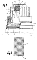
- Fig. 1 eine halbgeschnittene Seitenansicht eines erfindungsgemäßen Behälterverschlusses auf einem Behälterhals;
- Fig. 2 eine Schnittdarstellung eines beim Behälterverschluß nach Fig. 1 verwendeten Schwammkörpers in entspanntem Zustand;
- Fig. 3 einen Querschnitt durch eine abgewandelte Ausführungsform und im Betriebszustand des Gasablassens;
- Fign. 4 und 5 Querschitte durch weiterhin abgewandelte Ausführungsformen.
- Figure 1 is a half-sectional side view of a container closure according to the invention on a container neck.
- Figure 2 is a sectional view of a sponge body used in the container closure of Figure 1 in a relaxed state.
- 3 shows a cross section through a modified embodiment and in the operating state of gas discharge.
- Fig. 4 and 5 cross-sections through further modified embodiments.
Auf einem Behälterhals (1), auf den in der Ausführungform nach Fig. 1 noch ein Ausgießereinsatz (2) eingesetzt ist, sitzt eine aus Kunststoff bestehende Verschlußkappe (3), die mit einem Schraub- oder einem Bajonettverschluß (4) auf den Behälterhals (1) aufgesetzt ist. Über Stege (5), die als Zerreißstege die Orginalfüllung des Behälters anzeigen, ist die Verschlußkappe mit einem am Behälterhals befestigten und dort verbleibenden Garantiering (6) verbunden.On a container neck (1), on which a pouring insert (2) is inserted in the embodiment according to FIG. 1, there is a plastic closure cap (3) which is attached to the container neck with a screw or a bayonet catch (4). 1) is attached. The closure cap is connected to a guarantee ring (6) attached to the neck of the container and held there by means of webs (5) which show the original filling of the container as tearing webs.
Der Behälter, zu dem der dargestellte Behälterverschluß gehört, ist eine Kunststoffflasche zur Aufnahme eines Wäsche-Bleichmittels. Derartige Mittel neigen zur Gasentwicklung, was zu einer Aufblähung der Kunststoffflasche führen könnte. Die Verschlußkappe (3) ist deshalb mit einem Innendruckbegrenzerventil (11) ausgestattet. Zu diesem Zweck ist in der Oberseite der Kappe, also in deren radialer Deckfläche, eine Entgasungsöffnung (12) vorhanden, die aus dem Kappeninneren nach außen führt. Der Bereich, in dem sich die Öffnung (12) befindet, wird - und war beim dargestellten Beispiel exzentrisch - von einem von der Kappen-Deckwand zum Behälter zu vorstehenden Ringflansch (13) umgeben, auf den eine Abdeckkappe (14) aufgesteckt ist. Diese hat einen im wesentlichen zylindrischen Steckteil in Form von zwei Ringflanschen (15), (16), zwischen die der Ringflansch (3) einsteckbar ist. Aufgrund radialer Vorsprünge bzw. Rinnen in den Wänden der Ringflansche (13) und (15) ergeben sich beim Aufstecken der Abdeckkappe (14) auf den Ringflansch (13) elastische Verformungen, während anschließend die Abdeckkappe (14) festsitzt. Die elastischen Verformungen werden durch die Eigenschaften der für diese Bauteile verwendeten Kunststoffmaterialien ermöglicht. Im scheibenförmigen Boden (17) der Abdeckkappe (14) befindet sich ein zentrales Loch (18), das eine Öffnung im Boden bildet. Die Innenfläche (19) des Bodens (17) ist eben und glatt und die Innenfläche (20) des inneren Ringflanschs (16) der Abdeckkappe (14) ist zylindrisch und glatt. Das radiale Längenverhältnis zwischen der Öffnung (18) und der Fläche (19) liegt im Bereich von 1:3,5 bis 1:4, woraus ein Flächenverhältnis von 1:19 bis 1:24 resultiert.The container to which the container closure shown belongs is a plastic bottle for holding a laundry bleach. Such agents tend to develop gas, which could lead to inflation of the plastic bottle. The closure cap (3) is therefore equipped with an internal pressure relief valve (11). For this purpose, there is a degassing opening (12) in the top of the cap, that is to say in its radial top surface, which leads outward from the cap interior. The area in which the opening (12) is located - and was eccentric in the example shown - is surrounded by an annular flange (13) projecting from the cap top wall to the container and onto which a cover cap (14) is attached. This has an essentially cylindrical plug-in part in the form of two ring flanges (15), (16), between which the ring flange (3) can be inserted. Due to radial projections or grooves in the walls of the ring flanges (13) and (15), elastic deformations occur when the cover cap (14) is placed on the ring flange (13), while the cover cap (14) then sticks. The elastic deformations are due to the properties of these Components used plastic materials allows. In the disc-shaped bottom (17) of the cover cap (14) there is a central hole (18) which forms an opening in the bottom. The inner surface (19) of the bottom (17) is flat and smooth and the inner surface (20) of the inner ring flange (16) of the cover cap (14) is cylindrical and smooth. The radial length ratio between the opening (18) and the surface (19) is in the range from 1: 3.5 to 1: 4, which results in an area ratio of 1:19 to 1:24.
In dem von der aufgesteckten Abdeckkappe (14) und den angrenzenden Bereichen der Verschlußkappe (3) begrenzten Raum ist ein Schwammkörper (25) eingesetzt, der an seiner Unterseite mit einer Polyethylenfolie (26) kaschiert ist, die einen kreisförmigen Umfang (27) hat. Die Polyethylenfolie (26) überdeckt die gesamte Boden-Innenfläche (19) und das Loch (18). Der Schwammkörper ist in Fig. 2 in entspanntem Zustand dargestellt, während ihn die Schnittzeichnung von Fig. 1 zusammengedrückt zeigt. Durch die Zusammenpressung wird der Schwammkörper auf 1/5 seiner ursprünglichen Länge verkürzt. Diese erhebliche Zusammenpressung bewirkt, daß die Folie (26) mit nennenswerter Kraft auf die Fläche (19) gedrückt wird. Sie bewirkt dort eine Abdichtung, die für mäßige Drücke genügt, einschließlich des Drucks, den das Gewicht des Behälterinhalts im Fall des Kippens des Behälters ausübt.In the space delimited by the attached cover cap (14) and the adjacent areas of the closure cap (3), a sponge body (25) is inserted, which is laminated on its underside with a polyethylene film (26) that has a circular circumference (27). The polyethylene film (26) covers the entire inner floor surface (19) and the hole (18). The sponge body is shown in a relaxed state in FIG. 2, while the sectional drawing of FIG. 1 shows it compressed. The sponge body is shortened to 1/5 of its original length by the compression. This considerable compression causes the film (26) to be pressed onto the surface (19) with significant force. It creates a seal there which is sufficient for moderate pressures, including the pressure which the weight of the container contents exerts in the event of the container tipping over.
Der Schwammteil des Schammkörpers (25) besteht aus einem Material ausreichender Porosität, um ein Hindurchsickern des Gases, das aus dem Behälter abgeleitet werden soll, zu ermöglichen. Der Hinduchtritt von Flüssigkeit erfolgt sehr viel langsamer, und auch das Eindringen von Fremdkörpern und Fremdmaterialien in den Raum des Ventils (11) wird durch den Schwammkörper (25) verhindert.The sponge part of the sponge body (25) consists of a material of sufficient porosity to allow the gas to be seeped out to be discharged from the container. The passage of liquid is much slower, and the penetration of foreign bodies and foreign materials into the space of the valve (11) is prevented by the sponge body (25).
Als Material für die Folie (26) eignet sich auch Polyamid. Für den Schwammteil des Schwammkörpers (25) wird Polyetherschaumstoff bevorzugt, mit einer mittleren Rohdichte von 72 kg/m³, und einer Porenzahl von 20 bis 25 pro cm, einer Stauchhärte (nach ISO 3386) von 32kPa.Polyamide is also suitable as the material for the film (26). For the sponge part of the sponge body (25) polyether foam is preferred, with an average bulk density of 72 kg / m³, and one Number of pores from 20 to 25 per cm, a compression hardness (according to ISO 3386) of 32kPa.
Fig. 3, die nur den oberen Teil einer Verschlußkappe zeigt, betrifft eine Ausführungsform, bei der im scheibenförmigen Boden (17) der Abdeckkappe (14) anstelle des einen Lochs (18) mehrere Löcher (28) verhanden sind. Diese Löcher sind über die Innenfläche (19) verteilt, halten jedoch sämtlich einen Mindestabstand vom Ringflansch (16) und damit vom Rand des Schwammkörpers (25) ein. In der Deckenwand der Abdeckkappe (3) sind mehrere Entgasungsöffnungen (12) vorhanden, es sind zwei solcher Öffnungen sichtbar. Gemäß einer weiteren, nicht dargestellten Ausführung können die Entgasungsöffnungen und die Löcher auch jeweils als Sieb oder Gitter ausgeführt sein.Fig. 3, which shows only the upper part of a cap, relates to an embodiment in which in the disc-shaped bottom (17) of the cap (14) instead of the one hole (18) there are several holes (28). These holes are distributed over the inner surface (19), but all maintain a minimum distance from the ring flange (16) and thus from the edge of the sponge body (25). There are several degassing openings (12) in the top wall of the cover cap (3), two such openings are visible. According to a further embodiment, not shown, the degassing openings and the holes can also each be designed as a sieve or grille.
Fig. 1 zeigt den drucklosen Zustand und Fig. 3 den Zustand, in dem ein im Behälter befindlicher Überdruck gerade zu einem Entweichen von Gas führt. Die Folie (26) wird hierbei zunächst im Bereich der Löcher (28), bei weiter steigendem Druck aber weiter über der Fläche (19) ausholend von dieser abgehoben, wobei gleichzeitig der kreisförmige Rand der Folie (26) vom Ringflansch (16) nach innen weggezogen wird. Blasenweise oder stetig erreicht schließlich das durch die Löcher (28) tretende Gas diesen Rand und gerät in einen entstandenen Ringraum (30) zwischen dem Schwammkörper (25) und dem inneren Ringflansch (16). Von dort fließt das Gas durch den zusammengedrückten Schwammkörper (25) hindurch zu den Entgasungsöffnungen (12).Fig. 1 shows the unpressurized state and Fig. 3 shows the state in which an excess pressure in the container just leads to a gas escape. The film (26) is first lifted off the area (19) in the area of the holes (28), but with increasing pressure, but further above the surface (19), while the circular edge of the film (26) at the same time inwards from the ring flange (16) is pulled away. Finally, in bubbles or continuously, the gas passing through the holes (28) reaches this edge and enters an annular space (30) formed between the sponge body (25) and the inner annular flange (16). From there, the gas flows through the compressed sponge body (25) to the degassing openings (12).
Fig. 4 zeigt in einer Teildarstellung entsprechend der von Fig. 3 noch eine Ausführung, bei der die Unterseite der Abdeckhaube (14) anstelle der ebenen Scheibenform durch einen konischen Boden (32) gebildet ist, in dessen nach unten vorstehendem Scheitel sich das Loch (18) befindet. Der im entspannten Zustand gemäß Fig. 2 zylinderförmige Schwammkörper (25) mit der Polyethylenfolie (26) nimmt hier eine leicht "angespitzte" Form an, so daß die von ihm ausgeübte Flächenpressung im Bereich des Umfangs (27) höher ist als in der Nachbarschaft des Lochs (18). Hierdurch hebt sich beim Ansteigen des Drucks die Folie (26) allmählich von innen nach außen von der Fläche (19) ab, bis das Gas den Rand erreicht, und legt sich beim Nachlassen des Drucks sauber von außen nach innen wieder an die Fläche an.Fig. 4 shows in a partial representation corresponding to that of Fig. 3, an embodiment in which the underside of the cover (14) instead of the flat disc shape is formed by a conical bottom (32), in the top of which protrudes downwards, the hole ( 18) is located. The cylindrical sponge body (25) with the polyethylene film (26) in the relaxed state according to FIG. 2 assumes a slightly "sharpened" shape here, so that the surface pressure exerted by it is higher in the area of the circumference (27) than in the vicinity of the Lochs (18). As a result, the film (26) lifts when the pressure rises. gradually from the inside to the outside of the surface (19) until the gas reaches the edge, and when the pressure drops, it cleanly rests against the surface from the outside in.
Fig. 5 zeigt in einer Darstellung entsprechend Fig. 4 einen konischen Boden 32′, der nach innen vorsteht. Der Schwammkörper ist hierbei um das Loch 18 am stärksten und am Umfang am wenigsten vorgespannt. Ein Gasdruck, der die Folie am Loch 18 anheben kann, wird deshalb sofort schlagartig als zwischen der Folie (26) und der Fläche (19) hindurchlaufende Gasblase entladen.Fig. 5 shows in a representation corresponding to FIG. 4, a conical bottom 32 'which protrudes inwards. The sponge body is in this case the strongest around the
Claims (12)
Applications Claiming Priority (2)
| Application Number | Priority Date | Filing Date | Title |
|---|---|---|---|
| DE3903509A DE3903509A1 (en) | 1989-02-06 | 1989-02-06 | CONTAINER CAP WITH INTERNAL PRESSURE LIMITER |
| DE3903509 | 1989-02-06 |
Publications (3)
| Publication Number | Publication Date |
|---|---|
| EP0382146A1 true EP0382146A1 (en) | 1990-08-16 |
| EP0382146B1 EP0382146B1 (en) | 1993-06-09 |
| EP0382146B2 EP0382146B2 (en) | 1996-11-13 |
Family
ID=6373528
Family Applications (1)
| Application Number | Title | Priority Date | Filing Date |
|---|---|---|---|
| EP90102244A Expired - Lifetime EP0382146B2 (en) | 1989-02-06 | 1990-02-05 | Container closure with a safety valve |
Country Status (7)
| Country | Link |
|---|---|
| EP (1) | EP0382146B2 (en) |
| JP (1) | JP2742315B2 (en) |
| AU (1) | AU630149B2 (en) |
| BR (1) | BR9000501A (en) |
| DE (2) | DE3903509A1 (en) |
| ES (1) | ES2042091T5 (en) |
| ZA (1) | ZA90867B (en) |
Cited By (8)
| Publication number | Priority date | Publication date | Assignee | Title |
|---|---|---|---|---|
| DE9107432U1 (en) * | 1991-06-17 | 1991-08-22 | Frohn, Eric, 8000 Muenchen, De | |
| EP0519168A1 (en) * | 1991-06-17 | 1992-12-23 | Frohn, Eric, Dr.Jur. | Vent valve of a container for the transport of dangerous liquids |
| EP0669263A2 (en) * | 1994-02-22 | 1995-08-30 | Sotralentz S.A. | Container with ventilation device for flowable materials |
| EP0706954A1 (en) * | 1994-10-13 | 1996-04-17 | The Procter & Gamble Company | A process for manufacturing a venting cap, and a venting cap thus obtained |
| EP0967157A1 (en) * | 1998-06-25 | 1999-12-29 | Argo Sa | Semipermeable venting closure |
| EP1000871A1 (en) * | 1998-11-12 | 2000-05-17 | Dr. Ing. W. Frohn GmbH & Co. KG | Venting valve |
| CN101402408B (en) * | 2008-11-06 | 2010-06-02 | 常熟市亚德实业有限公司 | Security ventilating cover for closed-opening piling plastic vessel |
| FR2951919A1 (en) * | 2009-11-02 | 2011-05-06 | Oreal | Cosmetic product e.g. hair coloring product, packaging device, has filter whose outer layer covers foam layer, where outer layer is impermeable to liquid and permeable to gases to allow discharge of gases outside device through passage |
Families Citing this family (2)
| Publication number | Priority date | Publication date | Assignee | Title |
|---|---|---|---|---|
| EP2354032A1 (en) * | 2010-01-29 | 2011-08-10 | Goglio S.p.A. | Biodegradable one-way venting valve for an airtight container |
| CN106428886B (en) * | 2015-08-13 | 2018-04-06 | 天津市正阳彩印有限公司 | A kind of corrugated board packing box of dust control by ventilation |
Citations (4)
| Publication number | Priority date | Publication date | Assignee | Title |
|---|---|---|---|---|
| GB641201A (en) * | 1940-04-25 | 1950-08-09 | Pennsylvania Salt Mfg Co | Improvements in or relating to vented containers |
| US2626073A (en) * | 1948-06-30 | 1953-01-20 | Armstrong Cork Co | Venting closure and liner therefor |
| US4122943A (en) * | 1976-10-21 | 1978-10-31 | Jules Silver | Valved two compartment dispensing container |
| FR2605293A1 (en) * | 1986-10-15 | 1988-04-22 | Astra Plastique | Stopper equipped with a gas release valve |
Family Cites Families (6)
| Publication number | Priority date | Publication date | Assignee | Title |
|---|---|---|---|---|
| US3319836A (en) * | 1966-03-14 | 1967-05-16 | Colgate Palmolive Co | Spill-proof bottle closure |
| JPS5549316Y2 (en) * | 1975-05-12 | 1980-11-17 | ||
| US4089434A (en) * | 1976-12-10 | 1978-05-16 | Seling Sealing Products, Inc. | Venting liner |
| DE2834186C2 (en) * | 1978-08-04 | 1980-04-24 | Bodenseewerk Perkin-Elmer & Co Gmbh, 7770 Ueberlingen | Closure for sample bottles |
| DE8534913U1 (en) * | 1985-12-12 | 1986-02-06 | Kessel, Bernhard, 8071 Lenting | Closing member for a container subjected to internal pressure |
| JPS62125751U (en) * | 1986-02-01 | 1987-08-10 |
-
1989
- 1989-02-06 DE DE3903509A patent/DE3903509A1/en active Granted
-
1990
- 1990-02-01 AU AU49005/90A patent/AU630149B2/en not_active Ceased
- 1990-02-05 ES ES90102244T patent/ES2042091T5/en not_active Expired - Lifetime
- 1990-02-05 EP EP90102244A patent/EP0382146B2/en not_active Expired - Lifetime
- 1990-02-05 BR BR909000501A patent/BR9000501A/en not_active IP Right Cessation
- 1990-02-05 DE DE9090102244T patent/DE59001635D1/en not_active Expired - Fee Related
- 1990-02-06 ZA ZA90867A patent/ZA90867B/en unknown
- 1990-02-06 JP JP2027018A patent/JP2742315B2/en not_active Expired - Fee Related
Patent Citations (4)
| Publication number | Priority date | Publication date | Assignee | Title |
|---|---|---|---|---|
| GB641201A (en) * | 1940-04-25 | 1950-08-09 | Pennsylvania Salt Mfg Co | Improvements in or relating to vented containers |
| US2626073A (en) * | 1948-06-30 | 1953-01-20 | Armstrong Cork Co | Venting closure and liner therefor |
| US4122943A (en) * | 1976-10-21 | 1978-10-31 | Jules Silver | Valved two compartment dispensing container |
| FR2605293A1 (en) * | 1986-10-15 | 1988-04-22 | Astra Plastique | Stopper equipped with a gas release valve |
Cited By (9)
| Publication number | Priority date | Publication date | Assignee | Title |
|---|---|---|---|---|
| DE9107432U1 (en) * | 1991-06-17 | 1991-08-22 | Frohn, Eric, 8000 Muenchen, De | |
| EP0519168A1 (en) * | 1991-06-17 | 1992-12-23 | Frohn, Eric, Dr.Jur. | Vent valve of a container for the transport of dangerous liquids |
| EP0669263A2 (en) * | 1994-02-22 | 1995-08-30 | Sotralentz S.A. | Container with ventilation device for flowable materials |
| EP0669263A3 (en) * | 1994-02-22 | 1995-09-20 | Sotralentz Sa | |
| EP0706954A1 (en) * | 1994-10-13 | 1996-04-17 | The Procter & Gamble Company | A process for manufacturing a venting cap, and a venting cap thus obtained |
| EP0967157A1 (en) * | 1998-06-25 | 1999-12-29 | Argo Sa | Semipermeable venting closure |
| EP1000871A1 (en) * | 1998-11-12 | 2000-05-17 | Dr. Ing. W. Frohn GmbH & Co. KG | Venting valve |
| CN101402408B (en) * | 2008-11-06 | 2010-06-02 | 常熟市亚德实业有限公司 | Security ventilating cover for closed-opening piling plastic vessel |
| FR2951919A1 (en) * | 2009-11-02 | 2011-05-06 | Oreal | Cosmetic product e.g. hair coloring product, packaging device, has filter whose outer layer covers foam layer, where outer layer is impermeable to liquid and permeable to gases to allow discharge of gases outside device through passage |
Also Published As
| Publication number | Publication date |
|---|---|
| ES2042091T5 (en) | 1997-02-01 |
| BR9000501A (en) | 1991-01-15 |
| ES2042091T3 (en) | 1993-12-01 |
| ZA90867B (en) | 1991-10-30 |
| EP0382146B1 (en) | 1993-06-09 |
| AU630149B2 (en) | 1992-10-22 |
| AU4900590A (en) | 1990-08-09 |
| DE3903509A1 (en) | 1990-08-09 |
| EP0382146B2 (en) | 1996-11-13 |
| DE59001635D1 (en) | 1993-07-15 |
| JPH02269666A (en) | 1990-11-05 |
| JP2742315B2 (en) | 1998-04-22 |
| DE3903509C2 (en) | 1991-01-31 |
Similar Documents
| Publication | Publication Date | Title |
|---|---|---|
| DE1907358C3 (en) | Pumping device | |
| DE3125496C2 (en) | Pressure relief valve for venting packaging | |
| EP0133520B1 (en) | Container closure with venting means | |
| DE8411409U1 (en) | DEGASSING VALVE FOR STORAGE AND / OR TRANSPORT CONTAINERS | |
| DE2642298A1 (en) | DRINKING MOUTH FOR BOTTLES OR SIMILAR CONTAINERS | |
| DE102008019224A1 (en) | Valve arrangement for a pressurized fluid container | |
| DE3151606A1 (en) | BATTERY PLUG | |
| EP0382146B1 (en) | Container closure with a safety valve | |
| DE2549855A1 (en) | OVERPRESSURE VALVE, IN PARTICULAR FOR FLEXIBLE PACKAGING CONTAINERS | |
| DE2737326A1 (en) | VALVE ARRANGEMENT FOR AEROSOL TANK | |
| DE7417473U (en) | Liquid container with perforable locking cap | |
| EP1383689A1 (en) | Container closure and closure lid for said container closure | |
| AT524044B1 (en) | screw cap | |
| DE4122783A1 (en) | Bottle or other closure - has holder and seal part, with inward pointing protuberance holder gripping behind outer ridge on bottle neck | |
| WO1994002376A1 (en) | Threaded plug | |
| CH640327A5 (en) | Pressure relief valve for a gas-tight packaging bag | |
| DE2758432A1 (en) | SECURITY LATCH, IN PARTICULAR FOR FUEL TANK | |
| DE2140795A1 (en) | Pressure compensation device for a closed container | |
| EP0825131A1 (en) | Container for dispensing liquids by internal gaseous pressure | |
| EP0759401A1 (en) | Vent closure | |
| DE2614538A1 (en) | Resealable wine bottle stopper - has cylindrical portion with male thread fitting inside neck of bottle | |
| EP0519168B1 (en) | Vent valve of a container for the transport of dangerous liquids | |
| DE1432224A1 (en) | Vent seal for a closure | |
| DE2437668C3 (en) | Closing lids for liquid containers on motor vehicles | |
| DE6604498U (en) | END CAP FOR THE FILLING NECK OF FUEL CONTAINERS |
Legal Events
| Date | Code | Title | Description |
|---|---|---|---|
| PUAI | Public reference made under article 153(3) epc to a published international application that has entered the european phase |
Free format text: ORIGINAL CODE: 0009012 |
|
| AK | Designated contracting states |
Kind code of ref document: A1 Designated state(s): CH DE ES FR GB IT LI NL SE |
|
| 17P | Request for examination filed |
Effective date: 19901012 |
|
| 17Q | First examination report despatched |
Effective date: 19920402 |
|
| RAP3 | Party data changed (applicant data changed or rights of an application transferred) |
Owner name: UNILEVER PLC Owner name: UNILEVER N.V. |
|
| GRAA | (expected) grant |
Free format text: ORIGINAL CODE: 0009210 |
|
| AK | Designated contracting states |
Kind code of ref document: B1 Designated state(s): CH DE ES FR GB IT LI NL SE |
|
| GBT | Gb: translation of ep patent filed (gb section 77(6)(a)/1977) |
Effective date: 19930608 |
|
| REF | Corresponds to: |
Ref document number: 59001635 Country of ref document: DE Date of ref document: 19930715 |
|
| ET | Fr: translation filed | ||
| PLBI | Opposition filed |
Free format text: ORIGINAL CODE: 0009260 |
|
| ITF | It: translation for a ep patent filed |
Owner name: JACOBACCI CASETTA & PERANI S.P.A. |
|
| 26 | Opposition filed |
Opponent name: HENKEL KOMMANDITGESELLSCHAFT AUF AKTIEN Effective date: 19930821 |
|
| REG | Reference to a national code |
Ref country code: ES Ref legal event code: FG2A Ref document number: 2042091 Country of ref document: ES Kind code of ref document: T5 |
|
| NLR1 | Nl: opposition has been filed with the epo |
Opponent name: HENKEL KOMMANDITGESELLSCHAFT AUF AKTIEN |
|
| EAL | Se: european patent in force in sweden |
Ref document number: 90102244.2 |
|
| PLAW | Interlocutory decision in opposition |
Free format text: ORIGINAL CODE: EPIDOS IDOP |
|
| PLAW | Interlocutory decision in opposition |
Free format text: ORIGINAL CODE: EPIDOS IDOP |
|
| PUAH | Patent maintained in amended form |
Free format text: ORIGINAL CODE: 0009272 |
|
| STAA | Information on the status of an ep patent application or granted ep patent |
Free format text: STATUS: PATENT MAINTAINED AS AMENDED |
|
| 27A | Patent maintained in amended form |
Effective date: 19961113 |
|
| AK | Designated contracting states |
Kind code of ref document: B2 Designated state(s): CH DE ES FR GB IT LI NL SE |
|
| REG | Reference to a national code |
Ref country code: CH Ref legal event code: AEN Free format text: AUFRECHTERHALTUNG DES PATENTES IN GEAENDERTER FORM |
|
| ET3 | Fr: translation filed ** decision concerning opposition | ||
| NLR2 | Nl: decision of opposition | ||
| GBTA | Gb: translation of amended ep patent filed (gb section 77(6)(b)/1977) |
Effective date: 19961211 |
|
| ITF | It: translation for a ep patent filed |
Owner name: JACOBACCI & PERANI S.P.A. |
|
| PGFP | Annual fee paid to national office [announced via postgrant information from national office to epo] |
Ref country code: CH Payment date: 19970129 Year of fee payment: 8 |
|
| REG | Reference to a national code |
Ref country code: ES Ref legal event code: DC2A Kind code of ref document: T5 Effective date: 19961220 |
|
| NLR3 | Nl: receipt of modified translations in the netherlands language after an opposition procedure | ||
| PG25 | Lapsed in a contracting state [announced via postgrant information from national office to epo] |
Ref country code: LI Free format text: LAPSE BECAUSE OF NON-PAYMENT OF DUE FEES Effective date: 19980228 Ref country code: CH Free format text: LAPSE BECAUSE OF NON-PAYMENT OF DUE FEES Effective date: 19980228 |
|
| REG | Reference to a national code |
Ref country code: CH Ref legal event code: PL |
|
| REG | Reference to a national code |
Ref country code: GB Ref legal event code: IF02 |
|
| PGFP | Annual fee paid to national office [announced via postgrant information from national office to epo] |
Ref country code: ES Payment date: 20020222 Year of fee payment: 13 |
|
| PGFP | Annual fee paid to national office [announced via postgrant information from national office to epo] |
Ref country code: FR Payment date: 20030117 Year of fee payment: 14 |
|
| PGFP | Annual fee paid to national office [announced via postgrant information from national office to epo] |
Ref country code: SE Payment date: 20030121 Year of fee payment: 14 Ref country code: NL Payment date: 20030121 Year of fee payment: 14 |
|
| PGFP | Annual fee paid to national office [announced via postgrant information from national office to epo] |
Ref country code: GB Payment date: 20030129 Year of fee payment: 14 |
|
| PGFP | Annual fee paid to national office [announced via postgrant information from national office to epo] |
Ref country code: DE Payment date: 20030228 Year of fee payment: 14 |
|
| PG25 | Lapsed in a contracting state [announced via postgrant information from national office to epo] |
Ref country code: GB Free format text: LAPSE BECAUSE OF NON-PAYMENT OF DUE FEES Effective date: 20040205 |
|
| PG25 | Lapsed in a contracting state [announced via postgrant information from national office to epo] |
Ref country code: SE Free format text: LAPSE BECAUSE OF NON-PAYMENT OF DUE FEES Effective date: 20040206 Ref country code: ES Free format text: LAPSE BECAUSE OF NON-PAYMENT OF DUE FEES Effective date: 20040206 |
|
| PG25 | Lapsed in a contracting state [announced via postgrant information from national office to epo] |
Ref country code: NL Free format text: LAPSE BECAUSE OF NON-PAYMENT OF DUE FEES Effective date: 20040901 Ref country code: DE Free format text: LAPSE BECAUSE OF NON-PAYMENT OF DUE FEES Effective date: 20040901 |
|
| GBPC | Gb: european patent ceased through non-payment of renewal fee |
Effective date: 20040205 |
|
| EUG | Se: european patent has lapsed | ||
| PG25 | Lapsed in a contracting state [announced via postgrant information from national office to epo] |
Ref country code: FR Free format text: LAPSE BECAUSE OF NON-PAYMENT OF DUE FEES Effective date: 20041029 |
|
| NLV4 | Nl: lapsed or anulled due to non-payment of the annual fee |
Effective date: 20040901 |
|
| REG | Reference to a national code |
Ref country code: FR Ref legal event code: ST |
|
| PG25 | Lapsed in a contracting state [announced via postgrant information from national office to epo] |
Ref country code: IT Free format text: LAPSE BECAUSE OF NON-PAYMENT OF DUE FEES;WARNING: LAPSES OF ITALIAN PATENTS WITH EFFECTIVE DATE BEFORE 2007 MAY HAVE OCCURRED AT ANY TIME BEFORE 2007. THE CORRECT EFFECTIVE DATE MAY BE DIFFERENT FROM THE ONE RECORDED. Effective date: 20050205 |
|
| REG | Reference to a national code |
Ref country code: ES Ref legal event code: FD2A Effective date: 20040206 |