EP0380199A2 - Printer with interchangeable print heads - Google Patents
Printer with interchangeable print heads Download PDFInfo
- Publication number
- EP0380199A2 EP0380199A2 EP90300078A EP90300078A EP0380199A2 EP 0380199 A2 EP0380199 A2 EP 0380199A2 EP 90300078 A EP90300078 A EP 90300078A EP 90300078 A EP90300078 A EP 90300078A EP 0380199 A2 EP0380199 A2 EP 0380199A2
- Authority
- EP
- European Patent Office
- Prior art keywords
- printing head
- cartridge
- ink
- head cartridge
- type printing
- Prior art date
- Legal status (The legal status is an assumption and is not a legal conclusion. Google has not performed a legal analysis and makes no representation as to the accuracy of the status listed.)
- Granted
Links
- 238000007639 printing Methods 0.000 claims abstract description 89
- 238000007641 inkjet printing Methods 0.000 abstract 2
- 238000007651 thermal printing Methods 0.000 abstract 2
- 230000007246 mechanism Effects 0.000 description 3
- 238000010438 heat treatment Methods 0.000 description 2
- 238000000034 method Methods 0.000 description 2
- 230000008569 process Effects 0.000 description 2
- XAGFODPZIPBFFR-UHFFFAOYSA-N aluminium Chemical compound [Al] XAGFODPZIPBFFR-UHFFFAOYSA-N 0.000 description 1
- 229910052782 aluminium Inorganic materials 0.000 description 1
- 230000008901 benefit Effects 0.000 description 1
- 230000008859 change Effects 0.000 description 1
- 239000000470 constituent Substances 0.000 description 1
- 238000010276 construction Methods 0.000 description 1
- 230000000994 depressogenic effect Effects 0.000 description 1
- 230000007774 longterm Effects 0.000 description 1
- 230000004048 modification Effects 0.000 description 1
- 238000012986 modification Methods 0.000 description 1
- 230000005855 radiation Effects 0.000 description 1
- 238000006467 substitution reaction Methods 0.000 description 1
- 230000001960 triggered effect Effects 0.000 description 1
Images


Classifications
-
- B—PERFORMING OPERATIONS; TRANSPORTING
- B41—PRINTING; LINING MACHINES; TYPEWRITERS; STAMPS
- B41J—TYPEWRITERS; SELECTIVE PRINTING MECHANISMS, i.e. MECHANISMS PRINTING OTHERWISE THAN FROM A FORME; CORRECTION OF TYPOGRAPHICAL ERRORS
- B41J25/00—Actions or mechanisms not otherwise provided for
- B41J25/34—Bodily-changeable print heads or carriages
Definitions
- the terminal plate 12 is secured to the inner surface of the frontal wall 11a by means of two fixing pin sets 15 with the same engaged with holes 11e provided to the frontal wall 11a. Between the frontal wall 11a and the terminal plate 12 are inserted cushion elements 17.
- the terminal plate 12 carries a plurality of contact terminals 12a, from which parallel lead wires 16 are drawn out with thier outlet portion protected by the cover plate 14.
- the latch member 13 has an angled U-shape configuration consisting of two parallel leg plates 13b linked to each other by a handle plate 13a.
- the two parallel leg plates 13b are provided with their respective pivot tenons 13c on the lower rear portion and have their lower front corners cut off to form cartridge pressing edges 13d.
- the pulse currents to be supplied to the dot resistors 22a of a the thermal type cartridge (Fig. 2) and those to be supplied to the above-mentioned not shown ink-jet making resistors of the ink-jet type cartridge 30 (Fig. 3) are, in general, necessarily different in pulse width in accordance with their respective different functions; the dot resistors 22a heat a thermosensible sheet itself inserted on the platen roller 40 (Fig. 4), while the ink-jet making resistors heat, to make ink-jets, the capillaries (not shown) connecting between the ink-jet nozzles 33 and the ink reservoir 31.
Abstract
Description
- The present invention relates to a printer of the type that prints characters and the like by means of a printing head successively on a paper sheet fed on a platen roller, and more particularly to such a printer having the printing head devised so as to be changeable with another type printing head.
- Conventional printers whose printing mechanism consists essentially of a platen roller and a printing head for printing characters on a paper sheet fed on the platen roller can be classified tentatively into three types by the type of printing head used: an ink-jet type, a thermal type and a printing ribbon type. Of these three types, the last printing ribbon type printer is outside the present invention.
- The ink-jet type printer, in which the printing head is made up of a set of ink-jet nozzles combined with an ink fountain into a unit, has an advantage that the print face is clear and durable, and therefore, suitable for printing a formal document, definitive scientific data and others to be kept clear for a long term. However, the printer of this type has a disadvantage that the ink stored in the printing head may happen to be exhausted midway of printing continuously for a long time, for instance, in the case of printing a long series of data outputted from a scientific instrument automatically operating continuously. On the contrary, the thermal type printer, in which the printing head made up of a plurality of dot resistors thermally print characters on a thermosensible paper sheet, is free from such a disadvantage, but has a drawback that the printed characters are undurable and apt to fade away because the thermosensible paper is made to change color by heat and infrared radiations contained in the day light and ordinary lighting. Accordingly, the thermal type printer is unsuitable for printing a document or data to be kept clear for a long period of time.
- Such being the case, in many science laboratories, these two types of printers have conventionally been used properly in accordance with different printing purposes.
- The present invention aims at eliminating the above inconvenience involved in using printers, and makes it an object to provide a printer improved so as to serve both as an ink-jet type printer and as a thermal type printer.
- Another object of the present invention is to construct such an improved printer in a simple form by making the printing head of the printer changeable between an ink-jet type printing head and a thermal type printing head.
- To achieve the above objects, the essential part of a printer according to the present invention comprises an ink-jet type printing head cartridge, a thermal type printing head cartridge, a cartridge holder devised so as to accept any optionally selected one of the above two types of printing head cartridges, a sensor for detecting which type of the cartridges is mounted on the cartridge holder, and an electronic circuit for supplying pulse currents to heating resistors installed in the respective printing head cartridges.
- Instructed by a signal outputted from the sensor, the pulse currents supplied by the electronic circuit have their pulse width varied in accordance with the type of the printing head cartridge mounted on the cartridge holder.
- In the following the present invention is described in further detail with reference to the accompanying drawings, in which:
- Fig. 1 shows a disassembled view of the cartridge holder for holding in an embodiment of the present invention any one of the printing head cartridges shown in Figs. 2 and 3;
- Fig. 2 shows a perspective view of the thermal type printing head cartridge used in the above embodiment;
- Fig. 3 shows a perspective view of the ink-jet type printing head cartridge used in the above embodiment;
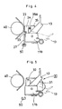
- Fig. 4 shows a side view illustrating the state that the thermal type printing head cartridge shown in Fig. 2 is mounted on the cartridge holder shown in Fig. 1;
- Fig. 5 shows a side view illustrating the state that the ink-jet type printing head cartridge shown in Fig. 3 is mounted on the cartridge holder shown in Fig. 1;
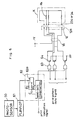
- Fig. 6 shows an electronic circuit for supplying, in the above embodiment, pulse currents to the printing head cartridges shown in Figs. 2 and 3; and
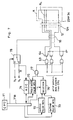
- Fig. 7 shows an electronic circuit for supplying, in another embodiment of the present invention, pulse currents to printing head cartridges substantially the same as those shown in Figs. 2 and 3.
- In an embodiment of the present invention, one of two printing head cartridges as shown in Figs. 2 and 3 is optionally mounted on a common cartridge holder whose disassembled view is shown in Fig. 1.
- Referring to Fig. 1 the
cartridge holder 10 is constituted essentially of a box-shaped main frame 11, aterminal plate 12, alatch member 13 and acover plate 14. The main frame 11 consists of afrontal wall 11a, twoside walls 11b and a bottom plate 11c. Thecartridge holder 10 is positioned so that thefrontal wall 11a of the main frame 11 may be directed toward a platen roller (not shown) to be coupled with this cartridge holder. Theterminal plate 12, which is pictured with bothsides 12b bent at a right angle, is inserted into the main frame 11 from below with thebent side portions 12a through twoslits 11d of the bottom plate 11c. Then, with the twobent sides 12a reopened flat, theterminal plate 12 is secured to the inner surface of thefrontal wall 11a by means of twofixing pin sets 15 with the same engaged withholes 11e provided to thefrontal wall 11a. Between thefrontal wall 11a and theterminal plate 12 are insertedcushion elements 17. Theterminal plate 12 carries a plurality ofcontact terminals 12a, from whichparallel lead wires 16 are drawn out with thier outlet portion protected by thecover plate 14. Thelatch member 13 has an angled U-shape configuration consisting of twoparallel leg plates 13b linked to each other by ahandle plate 13a. The twoparallel leg plates 13b are provided with their respective pivot tenons 13c on the lower rear portion and have their lower front corners cut off to formcartridge pressing edges 13d. The thus formedlatch member 13 is incorporated into the main frame 11 with the pivot tenons 13c engaged in bearing holes 11f provided to theside walls 11b of the main frame 11. The thus assembled cartridge holder accepts a printing head cartridge according to the present invention such that the cartridge has its trunk portion kept between theleg plates 13b of thelatch member 13. With thelatch member 13 turned to a standing posture, thecartridge pressing edges 13d press lateral protrusions provided to the cartridge, causing it to be thrusted to thefrontal wall 11a of the main frame 11 so that thecontact terminals 12a on theterminal plate 12 may come in contact with corresponding contact terminals provided to the cartridge. A pair of holes 18 (only one of which is seen in Fig. 1) on thefrontal wall 11a of the main frame 11 is to accept positioning tenons provided, as will be described later, to the cartridge to be mounted on thiscartridge holder 10. - The mechanism for making the cartridge holder 10 travel along a platen roller is not mentioned here, since it is out of the subject matter of the invention and may be any conventional one.
- Fig. 2 shows a thermal type
printing head cartridge 20 to be mounted on the above describedcartridge holder 10. This type of printing head cartridge consists essentially of athermal printer chip 22 on which are formed dot resistors 22a and theirleads 22b, aflexible circuit board 23 carrying thereon printed wirings 23b andcontact terminals 23a, a block-shaped heat radiator (made of aluminum) 24, aradiator stopper 25 andaframework 26 holding thestopper 25. Theradiator stopper 25 is provided, on its front surface, with a pair of positioningtenons 28 and a L-shaped arm 27 turning downward rectangularly. Thepositioning tenons 28 are engaged with the previously mentioned pair of holes 18 (Fig. 1) provided to thecartridge holder 10. - The function of the L-
shaped arm 27 is described later. Theframework 26 not only holds theheat radiator 24 but also makes both itssides 26b pivotally (24a) support the lower portion of theheat radiator 24 at the rear of the heat radiator stopper 25 so that theheat radiator 24 may have its upper part exposed above theradiator stopper 25. Theprinter chip 22 is held from below by theflexible circuit board 23, with theircorresponding leads 22b and wirings 23b electrically connected to each other. Theflexible circuit board 23 has its lower end fixed to the front surface of the radiator stopper 25 so that the back of theprinter chip 22 may get in touch with the upper part of theheat radiator 24. Further, theframework 26 pushes, by means of aspring 26a, theheat radiator 24 toward the radiator stopper 25 (in order to make theprinter chip 22 touch a thermosensible paper sheet). In the above constitution of this thermal type printing cartridge, both protrusions of the radiator stopper 25 over both thesides 26b of theframework 26 have their rear faces made to be contrapositive to thecartridge pressing edges 13d of the latch member 13 (Fig. 1) of thecartridge holder 10. A side view of thecartridge holder 10 carrying thereon this thermal typeprinting head cartridge 20 is shown, in conjunction with aplaten roller 40, in Fig. 4. Areference numeral 50 indicates a photosensor, which is shaded by the tip of the above-mentiond L-shaped arm 27. Thephotosensor 50 is to judge the thermal typeprinting head cartridge 20 to be mounted on thecartridge holder 10. - Fig. 3 shows an ink-jet
type printing head 30 to be mounted, as a substitution for the thermal typeprinting head cartridge 20, on thecartridge holder 10 shown in Fig. 1. This type of printing head cartridge consists essentially of anink reservoir 31 and afront plate 32 carrying thereon ink-jet nozzles 33,contact terminals 34,electric leads 35 connecting thecontact terminals 34 to resistors (not shown) built in the cartridge. Thefront plate 32 is further provided with a pair of positioningtenons 36. The resistors built in the cartridge are located near the not shown capillaries connecting the ink-jet nozzels 33 and theink reservoir 31, and make ink jets by being electrically energized. Since the functional principle and detailed inner construction of the ink-jet type printing head are conventionally known and out of the subject matter of the invention, their further description is omitted here. In this ink-jet typeprinting head cartridge 30 theink reservoir 31 constitutes the trunk portion of the cartridge, and thefront plate 32 has itsprotrusions 37 made to be contrapositive to thecartridge pressing edges 13d of the latch member 13 (Fig. 1) of thecartridge holder 10. A side view of thecartridge holder 10 carrying this ink-jet typeprinting head cartridge 30 is shown in Fig. 5, in conjunction with thesame platen roller 40 as shown in Fig. 4. Fig. 5 also showsthephotosensor 50. In this case thephotosensor 50 is left exposed to ambient light. - In the following is described an electronic circuit for energizing the resistors of the above two types of printing head cartridge. The pulse currents to be supplied to the dot resistors 22a of a the thermal type cartridge (Fig. 2) and those to be supplied to the above-mentioned not shown ink-jet making resistors of the ink-jet type cartridge 30 (Fig. 3) are, in general, necessarily different in pulse width in accordance with their respective different functions; the dot resistors 22a heat a thermosensible sheet itself inserted on the platen roller 40 (Fig. 4), while the ink-jet making resistors heat, to make ink-jets, the capillaries (not shown) connecting between the ink-
jet nozzles 33 and theink reservoir 31. - Referring to Fig. 6, which shows a circuit constitution for energizing the resistors of the printing head cartridges shown in Figs. 2 and 3, the photosensor 50 (refer also to Figs. 4 and 5) has its output signal inputted to a flip-
flop 61. Thus the flip-flop 61 outputs a high-level signal according to the type of the cartridge mounted on thecartridge holder 10. Namely, when the the thermal typeprinting head cartridge 20 is set on thecartridge holder 10, thephotosensor 50 has its output depressed to zero level by being shaded by the L-shaped arm 27 (refer to Fig. 4) causing the output of the flip-flop 61 to turn low level (or high level), whereas, since the ink-jet type printing head cartridge is not provided with a photosensor shading means, thephotosensor 50 outputs a positive signal, causing the fip-flop 61 to turn high level (or low level). According to the level of the flip-flop output, a one-shot multivibrator 62 has its time constant changed to either CR₁ or CR₂. The one-shot multivibrator 62, triggered by printing instruction signals, thus outputs pulse signals with their width changed in accordance with type of printing head cartridge mounted on thecartridge holder 10. The pulses outputted from the one-shot multivibrator 62 define the gate opening period of ANDgates 63 to which print pattern data signals are inputted. In this manner,transistors 64 can supply to resistors Rh (representing theresistors 22b of the thermal typeprinting head cartridge 20 or the built-in resistors of the ink-jet type printing head cartridge 30) resistor-heating pulse currents with their width varied in accordance with the type of the printing head cartridge mounted on thecartridge holder 10. In Fig. 6 the cartridge optionally selected is represented, with itscontact termimals 22a or 34 excluded, by a reference symbol K. - Needless to say, the above embodiment can be modified so as to function similarly with the photosensor shading arm (27) provided not to the thermal type printing head cartridge but to the ink-jet type printing head cartridge.
- The present invention is further embodied in another way, in which the type of the printing head cartridge mounted on the
cartridge holder 10 is identified by making use of a difference in resistance of the resistors installed in the two types of printing head cartridges. In this embodiment, all the constituents other than the electronic circuit portion are substantially the same as those of the above described and mentioned embodiment and modification, excepting that there is no photosensor needed and that, therefore, neither of the two types of printing head cartridge is provided with a photosensor shading arm. - Fig. 7 shows the microcomputerized electronic circuit for controlling, in this embodiment, current supply to the printing head cartridge mounted on the
cartridg holder 10. In Fig. 7 the components common to those used in the circuit shown in Fig. 6 are indicated with the same reference numerals and signs used in Fig. 6. - In this circuit the
transistors 64 have their collector circuits (with the resistors Rh included in series) current-supplied, through aswitch 78, from either of two voltage sources supplying voltages Vp and Vt, respectively. The voltage Vt is selected for judging which type of printing head cartridge is mounted on thecartridge holder 10, while the printing is carried out with the voltage Vp selected. The line related to the voltage Vt contains a resistor R in series. The voltage Vt is kept low enough (5 volts for example) to avoid operating a printing head cartridge, if mounted, during the process of judging the type of the cartridge. On the other hand, the voltage Vp for operating a printing head cartridge is typically 24 volts. Further, the ANDgates 63 switching thetransistors 64 have their gate signals are supplied from an ANDgate 77. Theswitch 78 is operated by an instruction of aCPU 71, which not only controls, through abus line 71a, also an A-D converter (analog-to-digital converter) 74, a printinstruction pulse generator 75, two gatingpulse generators selector 76, but also normally supplies print pattern data signals to the ANDgates 63. - In such a circuit constitution, with the
switch 78 turned to the line supplying the voltage Vt in the beginning, the printintruction pulse generator 75 and thegating pulse generator 72 output, respectively, a series of test pulses (which are not print instruction pulse signals) and another series of pulses covering said test pulses, with theselector 76 made to select the output from thegating pulse generator 72, and, at the same time, theCPU 71 directly supplies to the ANDgates 63 pulses (which are not print pattern data signals) equal to those outputted from thegateing pulse generator 72. Thus, thetransistors 64 are switched on for said test pulses. Under the circumstances, if no printing head cartridge is mounted on thecartridge holder 10, the resistor R outputs the voltage Vt as it is, since no currents flows in the collector circuits of thetransistors 64 owing to the omission of resistors Rh. TheA-D converter 74, instructed by theCPU 71, picks up and inputs the voltage Vt to theCPU 71. Then theCPU 71 judges any one of the printing head cartridges not to be mounted on thecartridge holder 10, and indicates the situation on a not shown display means or through any suitable alarm means. If any one of the two types of printing head cartridges has been mounted or is mounted according to the indication by theCPU 71, a series of pulse current reflecting the above mentioned test pulses flow the collector circuits of thetransistors 64, causing a potential drop on the resistor R. Since the potential drop depends on the resistance of the resistors Rh, namely on the type of the printing head cartridge mounted on thecartridge holder 10, theCPU 71 judges, from a voltage outputted from theA-D converter 74, which type printing head cartridge is mounted. - According to the type of the printing head cartridge mounted on the cartridge holder, the
CPU 71 instructs, with the switch turned to the line of the voltage Vp, the printinstruction pulse generator 75 to output predetermined print instruction pulse signals, and either of the two gatingpulse signal generators CPU 71 instructs, of course, theselector 76 to select the output of thegating pulse generator gates 63 supplied with print pattern data signals, the printer functions either as a thermal type printer or as an ink-jet type printer. Of course, the print pattern data signals are not directly inputted to the ANDgates 63 externally, but they are coded-signalized by theCPU 71 and then inputted to the ANDgates 63. The process of coding the print pattern data signals is well-known, and has its description is omitted here. - Incidentally, although the traveling of the
cartridge holder 10 is also controlled by theCPU 71, the details of the cartridge holder control function of theCPU 71 is also omitted in the present specification together with the mechanism of making the holder travel, since they are conventional and out of the subject matter of the invention.
Claims (2)
Applications Claiming Priority (2)
| Application Number | Priority Date | Filing Date | Title |
|---|---|---|---|
| JP19285/89 | 1989-01-27 | ||
| JP1019285A JPH02198881A (en) | 1989-01-27 | 1989-01-27 | Printer |
Publications (3)
| Publication Number | Publication Date |
|---|---|
| EP0380199A2 true EP0380199A2 (en) | 1990-08-01 |
| EP0380199A3 EP0380199A3 (en) | 1991-07-17 |
| EP0380199B1 EP0380199B1 (en) | 1995-08-02 |
Family
ID=11995176
Family Applications (1)
| Application Number | Title | Priority Date | Filing Date |
|---|---|---|---|
| EP90300078A Expired - Lifetime EP0380199B1 (en) | 1989-01-27 | 1990-01-04 | Printer with interchangeable print heads |
Country Status (4)
| Country | Link |
|---|---|
| US (1) | US5049904A (en) |
| EP (1) | EP0380199B1 (en) |
| JP (1) | JPH02198881A (en) |
| DE (1) | DE69021223T2 (en) |
Cited By (12)
| Publication number | Priority date | Publication date | Assignee | Title |
|---|---|---|---|---|
| EP0560562A2 (en) * | 1992-03-09 | 1993-09-15 | Canon Kabushiki Kaisha | Multi recording system using monochrome printer |
| EP0607928A2 (en) * | 1993-01-19 | 1994-07-27 | Canon Kabushiki Kaisha | Ink jet cartridge, ink jet apparatus and ink container |
| EP0581297A3 (en) * | 1992-07-30 | 1994-09-07 | Canon Kk | Recording head unit and recording apparatus using same |
| EP0622240A2 (en) * | 1993-04-30 | 1994-11-02 | Hewlett-Packard Company | Modular carriage assembly for an ink jet printer |
| EP0622233A2 (en) * | 1993-04-30 | 1994-11-02 | Hewlett-Packard Company | Electrical interconnect system for a printer |
| EP0647530A2 (en) * | 1993-10-11 | 1995-04-12 | Ing. C. Olivetti & C., S.p.A. | Printer with interchangeable printing heads |
| EP0694413A1 (en) * | 1994-07-29 | 1996-01-31 | Canon Kabushiki Kaisha | Printing apparatus with detachable printhead |
| EP0715958A2 (en) * | 1991-05-27 | 1996-06-12 | Seiko Epson Corporation | Ink catridge for ink jet recording apparatus |
| EP0692769A3 (en) * | 1994-07-14 | 1996-10-16 | Canon Kk | Printing apparatus and method |
| US5900898A (en) * | 1992-12-25 | 1999-05-04 | Canon Kabushiki Kaisha | Liquid jet head having a contoured and secured filter, liquid jet apparatus using same, and method of immovably securing a filter to a liquid receiving member of a liquid jet head |
| EP1017569A4 (en) * | 1997-02-10 | 2000-07-12 | Datacard Corp | Thermal print head module and method for using |
| US6264314B1 (en) | 1991-05-27 | 2001-07-24 | Seiko Epson Corporation | Ink cartridge for ink jet recording apparatus |
Families Citing this family (46)
| Publication number | Priority date | Publication date | Assignee | Title |
|---|---|---|---|---|
| US5155497A (en) * | 1991-07-30 | 1992-10-13 | Hewlett-Packard Company | Service station for ink-jet printer |
| US5363134A (en) * | 1992-05-20 | 1994-11-08 | Hewlett-Packard Corporation | Integrated circuit printhead for an ink jet printer including an integrated identification circuit |
| US5565900A (en) * | 1994-02-04 | 1996-10-15 | Hewlett-Packard Company | Unit print head assembly for ink-jet printing |
| US6305786B1 (en) | 1994-02-23 | 2001-10-23 | Hewlett-Packard Company | Unit print head assembly for an ink-jet printer |
| EP0759853A1 (en) * | 1994-04-21 | 1997-03-05 | Andersen, Allan | A graphical printer system |
| US5742313A (en) * | 1994-10-31 | 1998-04-21 | Spectra, Inc. | Efficient ink jet head arrangement |
| JPH0911527A (en) * | 1995-06-29 | 1997-01-14 | Tec Corp | Recording apparatus |
| US5748204A (en) * | 1995-09-20 | 1998-05-05 | Eastman Kodak Company | Hybrid imaging system capable of using ink jet and thermal dye transfer imaging technologies on a single image receiver |
| US5757394A (en) * | 1995-09-27 | 1998-05-26 | Lexmark International, Inc. | Ink jet print head identification circuit with programmed transistor array |
| US5940095A (en) * | 1995-09-27 | 1999-08-17 | Lexmark International, Inc. | Ink jet print head identification circuit with serial out, dynamic shift registers |
| KR0146539B1 (en) * | 1995-10-17 | 1998-08-17 | 김광호 | Detecting circuit and method of mounting ink cartridge |
| EP0819533A3 (en) * | 1996-07-12 | 1998-11-25 | Canon Kabushiki Kaisha | A method for standardizing an ink jet jet recording head and an ink jet recording head for attaining such standardization, ink jet recording method, and information processing apparatus, and host apparatus |
| US5877798A (en) * | 1997-03-21 | 1999-03-02 | Lexmark International Inc. | Method and apparatus for automatically determining the style printhead installed in a laser printer |
| US5943067A (en) * | 1997-04-28 | 1999-08-24 | Hewlett-Packard Company | Reusable media inkjet printing system |
| US5807005A (en) * | 1997-05-12 | 1998-09-15 | Lexmark International, Inc. | Cartridge lockout system and method |
| US6108101A (en) * | 1997-05-15 | 2000-08-22 | Canon Kabushiki Kaisha | Technique for printing with different printer heads |
| US6206506B1 (en) | 1997-11-17 | 2001-03-27 | Canon Kabushiki Kaisha | Ink jet printer having an ink cleaning mechanism |
| US6299274B1 (en) | 1997-12-15 | 2001-10-09 | Lexmark International, Inc. | Thermal ink jet printer cartridge identification |
| US6161915A (en) * | 1998-06-19 | 2000-12-19 | Lexmark International, Inc | Identification of thermal inkjet printer cartridges |
| US6151041A (en) * | 1998-10-19 | 2000-11-21 | Lexmark International, Inc. | Less restrictive print head cartridge installation in an ink jet printer |
| EP1013455B1 (en) | 1998-12-22 | 2006-02-15 | Eastman Kodak Company | A printer with donor and receiver media supply trays each adapted to allow a printer to sense type of media therein, and method of assembling the printer and trays |
| US6644544B1 (en) | 1999-06-16 | 2003-11-11 | Eastman Kodak Company | Imaging apparatus capable of forming an image consistent with type of imaging consumable loaded therein and method of assembling the apparatus |
| US6655785B1 (en) * | 1999-08-25 | 2003-12-02 | Xerox Corporation | Print element and method for assembling a print head |
| US6196665B1 (en) | 1999-12-03 | 2001-03-06 | Transact Technologies, Inc. | Latch for an ink cartridge |
| US6161920A (en) * | 2000-01-05 | 2000-12-19 | Hewlett-Packard Company | Techniques for adapting a small form factor ink-jet cartridge for use in a carriage sized for a large form factor cartridge |
| US6785739B1 (en) | 2000-02-23 | 2004-08-31 | Eastman Kodak Company | Data storage and retrieval playback apparatus for a still image receiver |
| US6527356B1 (en) | 2000-06-02 | 2003-03-04 | Eastman Kodak Company | Printer capable of forming an image on a receiver substrate according to type of receiver substrate and a method of assembling the printer |
| US6568785B1 (en) | 2002-03-18 | 2003-05-27 | Lexmark International, Inc | Integrated ink jet print head identification system |
| WO2004011263A1 (en) * | 2002-07-25 | 2004-02-05 | Matsushita Electric Industrial Co., Ltd. | Image recording device and imag recording method, and image receiving layer transfer element and image forming medium using them |
| EP1545885B1 (en) * | 2002-08-22 | 2010-11-17 | MVM Technologies, Inc. | Universal inkjet printer device |
| US7233498B2 (en) | 2002-09-27 | 2007-06-19 | Eastman Kodak Company | Medium having data storage and communication capabilities and method for forming same |
| KR100470579B1 (en) * | 2002-11-02 | 2005-03-08 | 삼성전자주식회사 | Controlling device of ink injection heater for ink-jet printer and controlling method thereof |
| US7109986B2 (en) | 2003-11-19 | 2006-09-19 | Eastman Kodak Company | Illumination apparatus |
| US7145464B2 (en) | 2003-11-19 | 2006-12-05 | Eastman Kodak Company | Data collection device |
| US7009494B2 (en) | 2003-11-21 | 2006-03-07 | Eastman Kodak Company | Media holder having communication capabilities |
| US9296214B2 (en) | 2004-07-02 | 2016-03-29 | Zih Corp. | Thermal print head usage monitor and method for using the monitor |
| US20060012634A1 (en) * | 2004-07-15 | 2006-01-19 | Squie Roger W | Print cartridge adapter |
| US8035482B2 (en) | 2004-09-07 | 2011-10-11 | Eastman Kodak Company | System for updating a content bearing medium |
| WO2006062686A2 (en) * | 2004-11-12 | 2006-06-15 | Pertech Resources Inc. | Transaction printer |
| KR20060053487A (en) * | 2004-11-16 | 2006-05-22 | 삼성전자주식회사 | Thermal transfer image forming device and method using lvds(low voltage differential signaling) |
| KR20060067689A (en) * | 2004-12-15 | 2006-06-20 | 삼성전자주식회사 | Thermal transfer image forming device and method using lvds(low voltage differential signaling) |
| US7604317B2 (en) * | 2005-06-21 | 2009-10-20 | Canon Kabushiki Kaisha | Recording apparatus capable of checking positions of ink containers, and method for checking the positions |
| JP4756928B2 (en) * | 2005-06-21 | 2011-08-24 | キヤノン株式会社 | Printer |
| US8721203B2 (en) | 2005-10-06 | 2014-05-13 | Zih Corp. | Memory system and method for consumables of a printer |
| DE102006036716B3 (en) * | 2006-06-02 | 2007-09-27 | Artech Gmbh Design + Production In Plastic | Printer e.g. inkjet printer, retrofitting device, has cartridge retaining device to retain replaceable original ink cartridges, and locking pin to lock fastener in fastening position when insert-ink cartridge is attached in retaining device |
| JP7161700B2 (en) * | 2018-09-28 | 2022-10-27 | 株式会社リコー | Image forming apparatus and main body of image forming apparatus |
Citations (5)
| Publication number | Priority date | Publication date | Assignee | Title |
|---|---|---|---|---|
| JPS5942984A (en) * | 1982-09-03 | 1984-03-09 | Hitachi Ltd | Printer |
| EP0255867A2 (en) * | 1986-07-04 | 1988-02-17 | Siemens Aktiengesellschaft | Ink jet printer with an exchangeable print head |
| JPS63130346A (en) * | 1986-11-20 | 1988-06-02 | Tokyo Electric Co Ltd | Dot printer |
| EP0352698A2 (en) * | 1988-07-25 | 1990-01-31 | Siemens Nixdorf Informationssysteme Aktiengesellschaft | Method for producing information concerning a type of print head |
| EP0195949B1 (en) * | 1985-03-28 | 1990-05-02 | Siemens Nixdorf Informationssysteme Aktiengesellschaft | Printer with one or more print stations |
Family Cites Families (6)
| Publication number | Priority date | Publication date | Assignee | Title |
|---|---|---|---|---|
| JPS55152080A (en) * | 1979-05-16 | 1980-11-27 | Canon Inc | Recorder |
| EP0097744B1 (en) * | 1982-06-30 | 1986-09-24 | International Business Machines Corporation | Print head assembly for non-impact printing |
| JPS6024983A (en) * | 1983-07-20 | 1985-02-07 | Canon Inc | Printer |
| JPS60204333A (en) * | 1984-03-30 | 1985-10-15 | Canon Inc | Liquid jet recording device |
| US4736213A (en) * | 1986-12-22 | 1988-04-05 | Eastman Kodak Company | Multiple print/cartridge ink jet printer having accurate vertical interpositioning |
| US4872027A (en) * | 1987-11-03 | 1989-10-03 | Hewlett-Packard Company | Printer having identifiable interchangeable heads |
-
1989
- 1989-01-27 JP JP1019285A patent/JPH02198881A/en active Pending
- 1989-12-29 US US07/458,885 patent/US5049904A/en not_active Expired - Fee Related
-
1990
- 1990-01-04 DE DE69021223T patent/DE69021223T2/en not_active Expired - Fee Related
- 1990-01-04 EP EP90300078A patent/EP0380199B1/en not_active Expired - Lifetime
Patent Citations (5)
| Publication number | Priority date | Publication date | Assignee | Title |
|---|---|---|---|---|
| JPS5942984A (en) * | 1982-09-03 | 1984-03-09 | Hitachi Ltd | Printer |
| EP0195949B1 (en) * | 1985-03-28 | 1990-05-02 | Siemens Nixdorf Informationssysteme Aktiengesellschaft | Printer with one or more print stations |
| EP0255867A2 (en) * | 1986-07-04 | 1988-02-17 | Siemens Aktiengesellschaft | Ink jet printer with an exchangeable print head |
| JPS63130346A (en) * | 1986-11-20 | 1988-06-02 | Tokyo Electric Co Ltd | Dot printer |
| EP0352698A2 (en) * | 1988-07-25 | 1990-01-31 | Siemens Nixdorf Informationssysteme Aktiengesellschaft | Method for producing information concerning a type of print head |
Non-Patent Citations (2)
| Title |
|---|
| PATENT ABSTRACTS OF JAPAN vol. 12, no. 378 (M-751)(3225) 11 October 1988, & JP-A-63 130346 (SHINICHI AKIMOTO ET AL) 02 June 1988, * |
| PATENT ABSTRACTS OF JAPAN vol. 8, no. 146 (M-307)(1583) 07 July 1984, & JP-A-59 042984 (MAREO SUDOU ET AL) 09 March 1984, * |
Cited By (28)
| Publication number | Priority date | Publication date | Assignee | Title |
|---|---|---|---|---|
| US5666146A (en) * | 1991-05-27 | 1997-09-09 | Seiko Epson Corporation | Ink cartridge for ink jet recording apparatus |
| EP0715958A3 (en) * | 1991-05-27 | 1996-07-17 | Seiko Epson Corp | |
| EP0715958A2 (en) * | 1991-05-27 | 1996-06-12 | Seiko Epson Corporation | Ink catridge for ink jet recording apparatus |
| US6264314B1 (en) | 1991-05-27 | 2001-07-24 | Seiko Epson Corporation | Ink cartridge for ink jet recording apparatus |
| US6053595A (en) * | 1992-03-09 | 2000-04-25 | Canon Kabushiki Kaisha | Multi recording system using monochrome printer |
| EP0560562A3 (en) * | 1992-03-09 | 1994-03-30 | Canon Kk | Multi recording system using monochrome printer |
| EP0560562A2 (en) * | 1992-03-09 | 1993-09-15 | Canon Kabushiki Kaisha | Multi recording system using monochrome printer |
| US6151046A (en) * | 1992-07-30 | 2000-11-21 | Canon Kabushiki Kaisha | Recording head unit and recording apparatus using the same |
| EP0581297A3 (en) * | 1992-07-30 | 1994-09-07 | Canon Kk | Recording head unit and recording apparatus using same |
| US5900898A (en) * | 1992-12-25 | 1999-05-04 | Canon Kabushiki Kaisha | Liquid jet head having a contoured and secured filter, liquid jet apparatus using same, and method of immovably securing a filter to a liquid receiving member of a liquid jet head |
| EP0607928A3 (en) * | 1993-01-19 | 1996-03-27 | Canon Kk | Ink jet cartridge, ink jet apparatus and ink container. |
| US6203149B1 (en) | 1993-01-19 | 2001-03-20 | Canon Kabushiki Kaisha | Ink jet cartridge, ink jet apparatus and ink container |
| US5940102A (en) * | 1993-01-19 | 1999-08-17 | Canon Kabushiki Kaisha | Ink jet cartridge, ink jet apparatus and ink container |
| EP0607928A2 (en) * | 1993-01-19 | 1994-07-27 | Canon Kabushiki Kaisha | Ink jet cartridge, ink jet apparatus and ink container |
| EP0622240A3 (en) * | 1993-04-30 | 1996-04-03 | Hewlett Packard Co | Modular carriage assembly for an ink jet printer. |
| EP0622233A3 (en) * | 1993-04-30 | 1995-06-07 | Hewlett Packard Co | Electrical interconnect system for a printer. |
| EP0622233A2 (en) * | 1993-04-30 | 1994-11-02 | Hewlett-Packard Company | Electrical interconnect system for a printer |
| EP0622240A2 (en) * | 1993-04-30 | 1994-11-02 | Hewlett-Packard Company | Modular carriage assembly for an ink jet printer |
| EP0647530A3 (en) * | 1993-10-11 | 1995-07-12 | Olivetti & Co Spa | Printer with interchangeable printing heads. |
| EP0647530A2 (en) * | 1993-10-11 | 1995-04-12 | Ing. C. Olivetti & C., S.p.A. | Printer with interchangeable printing heads |
| EP0692769A3 (en) * | 1994-07-14 | 1996-10-16 | Canon Kk | Printing apparatus and method |
| US5949445A (en) * | 1994-07-14 | 1999-09-07 | Canon Kabushiki Kaisha | Printing apparatus and method |
| CN1067335C (en) * | 1994-07-14 | 2001-06-20 | 佳能株式会社 | Printing apparatus and method |
| US5711619A (en) * | 1994-07-29 | 1998-01-27 | Canon Kabushiki Kaisha | Printing apparatus |
| EP0694413A1 (en) * | 1994-07-29 | 1996-01-31 | Canon Kabushiki Kaisha | Printing apparatus with detachable printhead |
| EP1017569A4 (en) * | 1997-02-10 | 2000-07-12 | Datacard Corp | Thermal print head module and method for using |
| EP1017569A1 (en) * | 1997-02-10 | 2000-07-12 | Datacard Corporation | Thermal print head module and method for using |
| EP1486342A1 (en) * | 1997-02-10 | 2004-12-15 | Datacard Corporation | Thermal print head module and method for using |
Also Published As
| Publication number | Publication date |
|---|---|
| DE69021223T2 (en) | 1996-03-14 |
| JPH02198881A (en) | 1990-08-07 |
| EP0380199B1 (en) | 1995-08-02 |
| DE69021223D1 (en) | 1995-09-07 |
| EP0380199A3 (en) | 1991-07-17 |
| US5049904A (en) | 1991-09-17 |
Similar Documents
| Publication | Publication Date | Title |
|---|---|---|
| EP0380199B1 (en) | Printer with interchangeable print heads | |
| US3845850A (en) | Thermal printer | |
| US4741634A (en) | Printer with variable head displacement | |
| ES2142911T3 (en) | PRINTING HEAD AND PRINTING DEVICE USING THE SAME. | |
| US5669720A (en) | Thermal printer with minimized power difference between sequentially driven blocks of printing elements | |
| JPS6337970A (en) | Dot printer | |
| KR920007369B1 (en) | Printing character control apparatus for thermal head | |
| US6293717B1 (en) | Tape printing apparatus and tape printing method | |
| JP2758891B2 (en) | Ink cartridge detection circuit and detection method for ink jet recording apparatus | |
| US5897228A (en) | Camera with low cost interchangeable pushbutton annotation | |
| US6095700A (en) | Battery operated thermal printer with means to optimize battery life | |
| KR20010027257A (en) | Apparatus for decision of cartridge type in the printer for micro injecting device | |
| GB2356375A (en) | Method of controlling a thermal print head | |
| EP0168474B1 (en) | Position indicator means for an electrically controlled device such as a printer | |
| JP3521625B2 (en) | Ink level detector | |
| US4471442A (en) | Modular electronic measuring and printing unit | |
| JP2864560B2 (en) | Printer | |
| JP2659571B2 (en) | Paper feeder | |
| JPS63139774A (en) | Printer | |
| US5311270A (en) | Paper cassette having a plurality of switches for selecting an input data port | |
| JPS6239271A (en) | Thermal printer | |
| JP2010253788A (en) | Thermal head and thermal printer | |
| EP0214162A1 (en) | Computer-controlled printing and marking device | |
| RU2008228C1 (en) | Portable typewriter | |
| JPS6259675B2 (en) |
Legal Events
| Date | Code | Title | Description |
|---|---|---|---|
| PUAI | Public reference made under article 153(3) epc to a published international application that has entered the european phase |
Free format text: ORIGINAL CODE: 0009012 |
|
| AK | Designated contracting states |
Kind code of ref document: A2 Designated state(s): DE FR GB |
|
| PUAL | Search report despatched |
Free format text: ORIGINAL CODE: 0009013 |
|
| AK | Designated contracting states |
Kind code of ref document: A3 Designated state(s): DE FR GB |
|
| 17P | Request for examination filed |
Effective date: 19920114 |
|
| 17Q | First examination report despatched |
Effective date: 19930818 |
|
| GRAA | (expected) grant |
Free format text: ORIGINAL CODE: 0009210 |
|
| AK | Designated contracting states |
Kind code of ref document: B1 Designated state(s): DE FR GB |
|
| REF | Corresponds to: |
Ref document number: 69021223 Country of ref document: DE Date of ref document: 19950907 |
|
| ET | Fr: translation filed | ||
| PLBE | No opposition filed within time limit |
Free format text: ORIGINAL CODE: 0009261 |
|
| STAA | Information on the status of an ep patent application or granted ep patent |
Free format text: STATUS: NO OPPOSITION FILED WITHIN TIME LIMIT |
|
| 26N | No opposition filed | ||
| PGFP | Annual fee paid to national office [announced via postgrant information from national office to epo] |
Ref country code: GB Payment date: 19971229 Year of fee payment: 9 |
|
| PGFP | Annual fee paid to national office [announced via postgrant information from national office to epo] |
Ref country code: FR Payment date: 19980109 Year of fee payment: 9 |
|
| PGFP | Annual fee paid to national office [announced via postgrant information from national office to epo] |
Ref country code: DE Payment date: 19980112 Year of fee payment: 9 |
|
| PG25 | Lapsed in a contracting state [announced via postgrant information from national office to epo] |
Ref country code: GB Free format text: LAPSE BECAUSE OF NON-PAYMENT OF DUE FEES Effective date: 19990104 |
|
| GBPC | Gb: european patent ceased through non-payment of renewal fee |
Effective date: 19990104 |
|
| PG25 | Lapsed in a contracting state [announced via postgrant information from national office to epo] |
Ref country code: FR Free format text: LAPSE BECAUSE OF NON-PAYMENT OF DUE FEES Effective date: 19990930 |
|
| PG25 | Lapsed in a contracting state [announced via postgrant information from national office to epo] |
Ref country code: DE Free format text: LAPSE BECAUSE OF NON-PAYMENT OF DUE FEES Effective date: 19991103 |
|
| REG | Reference to a national code |
Ref country code: FR Ref legal event code: ST |