EP0379079A1 - - Apparatus for surveying the surface of an object by projection of fringe patterns - Google Patents
- Apparatus for surveying the surface of an object by projection of fringe patterns Download PDFInfo
- Publication number
- EP0379079A1 EP0379079A1 EP90100588A EP90100588A EP0379079A1 EP 0379079 A1 EP0379079 A1 EP 0379079A1 EP 90100588 A EP90100588 A EP 90100588A EP 90100588 A EP90100588 A EP 90100588A EP 0379079 A1 EP0379079 A1 EP 0379079A1
- Authority
- EP
- European Patent Office
- Prior art keywords
- phi
- values
- brightness
- points
- lambda
- Prior art date
- Legal status (The legal status is an assumption and is not a legal conclusion. Google has not performed a legal analysis and makes no representation as to the accuracy of the status listed.)
- Granted
Links
- 238000000034 method Methods 0.000 claims abstract description 16
- 238000009826 distribution Methods 0.000 claims description 33
- 230000015654 memory Effects 0.000 claims description 12
- 238000005286 illumination Methods 0.000 claims description 10
- 238000005259 measurement Methods 0.000 claims description 6
- 230000000737 periodic effect Effects 0.000 claims description 5
- 238000006073 displacement reaction Methods 0.000 claims description 4
- 230000006870 function Effects 0.000 claims description 4
- 230000015572 biosynthetic process Effects 0.000 claims 1
- 230000005622 photoelectricity Effects 0.000 claims 1
- 238000011156 evaluation Methods 0.000 description 6
- 230000003287 optical effect Effects 0.000 description 5
- 238000010586 diagram Methods 0.000 description 2
- 238000006243 chemical reaction Methods 0.000 description 1
- 230000001419 dependent effect Effects 0.000 description 1
- 238000011161 development Methods 0.000 description 1
- 230000018109 developmental process Effects 0.000 description 1
- 230000000694 effects Effects 0.000 description 1
- 238000000691 measurement method Methods 0.000 description 1
- 230000010363 phase shift Effects 0.000 description 1
- 239000011295 pitch Substances 0.000 description 1
- 238000010008 shearing Methods 0.000 description 1
- 238000004441 surface measurement Methods 0.000 description 1
Images

Classifications
-
- G—PHYSICS
- G01—MEASURING; TESTING
- G01B—MEASURING LENGTH, THICKNESS OR SIMILAR LINEAR DIMENSIONS; MEASURING ANGLES; MEASURING AREAS; MEASURING IRREGULARITIES OF SURFACES OR CONTOURS
- G01B11/00—Measuring arrangements characterised by the use of optical techniques
- G01B11/24—Measuring arrangements characterised by the use of optical techniques for measuring contours or curvatures
- G01B11/25—Measuring arrangements characterised by the use of optical techniques for measuring contours or curvatures by projecting a pattern, e.g. one or more lines, moiré fringes on the object
- G01B11/2536—Measuring arrangements characterised by the use of optical techniques for measuring contours or curvatures by projecting a pattern, e.g. one or more lines, moiré fringes on the object using several gratings with variable grating pitch, projected on the object with the same angle of incidence
Definitions
- the invention relates to a method for measuring the surface of an object, wherein - the object is illuminated with a light beam with a brightness distribution that varies periodically over its cross section, - the phases of the brightness distribution of the light beam are illuminated for illumination at the object points to be measured, - the brightness values of the Illuminated object points for a number of different modulation phases and period lengths of the light bundle for illumination are recorded and stored by means of a photoelectric detector arrangement, and - the detected brightness values for determining the residual phase values of the illuminated object points within the periods of the brightness distribution for defined phase positions of the distributions with respect to a reference plane and for determining the height of the points of the object surface with respect to the reference plane.
- the invention also relates to a device for measuring the surface of an object with - means for illuminating the object with a light beam with a brightness distribution that varies periodically over its cross section, - means for modulating the phases of the brightness distribution of the light beam for lighting at the object points to be measured, - one Photoelectric detector arrangement for recording and storing the brightness values of the illuminated object points for a number of different modulation phases and period lengths of the light bundle for illumination and with - means for linking the detected brightness values to determine the remaining phase values of the illuminated object points within the periods of the brightness distribution for defined phase positions of the distributions compared to Means for lighting, and for determining the heights of the points of the object surface with respect to a reference plane.
- a periodic stripe pattern is projected onto the surface to be measured, and a stripe image deformed by the shape of the surface is evaluated in order to calculate the heights of the individual points of the object surface with respect to a reference plane.
- Various methods are known for generating the stripe pattern. According to C.L. Koliopoulos: "Interferometric Optical Phase Measurement Techniques" (dissertation, Univ. Of Arizona, 1981) the stripe patterns are generated with a Mirau interferometer or with a Twyman-Green interferometer.
- the stripe width or the period length of the stripe pattern is essentially determined by the wavelength of the light used for illumination and the position of the reference mirror.
- the stripe patterns are generated with a shearing interferometer or by projecting a sinus grating.
- the period length can be determined by setting the shear angle or by choosing an appropriate sine grid.
- the period length of the stripe pattern essentially determines the depth resolution of the surface measurement.
- the object of the invention is to find a method for measuring the surface of an object and a device for carrying it out, which allow a simplified determination of the absolute height of object points with respect to a reference plane.
- This task is performed in a process of the type mentioned at the beginning solved in that - from the residual phase values for several period lengths and defined phase positions of the brightness distributions of the illuminating light bundle relative to the object surface, the absolute heights of the object points to be measured are determined with respect to the reference plane.
- a device of the type mentioned above for carrying out this method is characterized in that - the means for lighting and for modulation comprise several linear grids with different period lengths, which are arranged in the light beam on a common carrier, that - at least one on the common carrier further division is arranged, which includes reference marks and with respect to which the linear grids have defined phase positions and that - means are provided for the defined displacement of the common support and for scanning the further division, which allow the linear grids to be shifted in the light beam in such a way that the corresponding brightness distributions with respect to the object surface have the required defined phase positions.
- the surface 1 of an object is illuminated by the light of a projector 2 with the optical axis 3 and recorded by a photoelectric detector arrangement camera 4 with the optical axis 5.
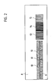
- the light beam of a light-emitting diode 20 in the projector 2 is first directed in parallel by means of a collecting optics. This light beam then illuminates a plurality of linear optical grids, which are located on a transparent graduation carrier 8. As Fig.2 shows, these grids are all oriented parallel to each other.
- a long grating 9 with zero marks 10 arranged next to it has a relatively short period length and is used in a manner known per se to measure the position of the graduation carrier 8 which is displaceable in a guide fastened to the projector 2.
- the grating 9 is assigned a photoelectric scanning system 11, the output signals of which are fed via a line 12 to an evaluation device.
- the line 12 also serves to supply power to the scanning system 11.
- the grating 9 In addition to the grating 9, three further grids 13, 14, 15 are arranged, which are projected onto the surface 1 of the object to be measured.
- the pitches of these three Ronchi gratings 13, 14, 15 consist of equally wide straight lines and gaps, the period length of the grating 13 being 1.26 mm, that of the grating 14 being 1.12 mm and that of the grating 15 being 0.28 mm.
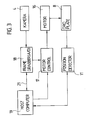
- the division carrier 8 is displaceable in a parallel guide by means of a fastening angle. The displacement takes place via a stepper motor 16, which is driven by a cable from a control stage Motor Control 17, as shown in FIG. 3. It is measured with the scanning system 11 and the grating divisions 9, 10. After passing through one of the gratings 13, 14 or 15, the light bundle of the diode 20 has a brightness distribution which varies periodically over its cross section. This light beam is widened by two optics to a cross section corresponding to object 1.
- the object surface 1 is thus illuminated with a periodic stripe pattern which can be shifted to the right or left by shifting the division carrier 8 to the side.
- the lighting phase changes periodically for all object points; phase modulation is present.
- reference signals can be generated if certain Object points go through certain lighting phases.
- This evaluation takes place according to a predetermined time sequence, which is given by the recording standard of the detector arrangement camera 4.
- the stepping motor 16 is controlled by the time sequence given by the recording standard of the camera 4 such that the strip image on the object 1 is shifted by 1/1 period length during the recording of the images.
- the detector arrangement camera 4 comprises a CCD sensor with more than 262 144 individual sensors. These individual sensors integrate the individual pixel illuminations for 20 ms each during the image shift, and then read out an overall image in each case into a memory of the frame grabber 18 evaluation electronics (see FIG. 3).
- the images output by the camera 4 are converted pixel by pixel into a digital signal format by an analog-digital converter (ADC) located in the frame grabber 18.
- ADC analog-digital converter
- the resulting 8-bit image pixel values are transferred to an add / subtract stage.
- the add / subtract stage adopts the values stored in the memories of the frame grabber 18 and returns the new values to the memories after the arithmetic operation.
- image sums (B-D) stored in one memory by image sums (A-C) stored in the other memory is carried out on the frame grabber 18 with the aid of "look-up tables" (LUT). Both image sums are first logarithmized using the LUT, and the logarithms are then subtracted from one another. By means of a further LUT, the antilogarithm and the function (arc tan) are then formed from the resulting difference.
- 262 144 values are obtained for the 262 144 pixels, from which the object point heights are calculated. Specifically, for all values from M1 log (M1) is formed, these are saved again in M1, for all values from M2 log (M2) are saved, these are saved again in M2, the difference between the stored values M1-M2 is formed and saved again in M1.
- the required residual phase values phi within the projected grating strips can in the case of a rectangular brightness distribution of the strips with an error of about 1 percent by forming the function arctan ⁇ log (-1) M1 ⁇ , otherwise be calculated using a corresponding stored value table (LUT).
- the residual phase values phi thus determined determine the heights of the individual object points within a strip of the projected pattern with respect to the lower edge of this strip.
- the absolute heights of the object points to be measured with respect to a reference plane are now determined according to the invention from the residual phase values for several period lengths of the brightness distributions on the object surface.
- the period lengths lambda effective for the height measurement are compared to the Period length lambda (0) of the projected stripe pattern increased by the factor (1 / cos (alpha)). It is now assumed that two stripe patterns with the effective period lengths lambda (1) and lambda (2) are projected so that they are in phase for a reference height of the object, that lambda (1)> lambda (2), e.g.
- n (1) p * M (2) + m (r) be calculated. This takes place in a host computer 19 (FIG. 3) which is connected to the frame grabber 18 via a line 21.
- the one described here has the following advantages:
- the determination of the absolute height of each point on the surface of the object 1 takes place without knowledge of the heights of neighboring points, the surface can therefore be discontinuous due to height jumps, and it can also consist of individual non-contiguous ones Parts exist.
- the exemplary embodiment described allows numerous variants and forms of use.
- the accuracy of the determined absolute heights z can be improved by using a brightness distribution with a period length that is significantly smaller than the period lengths of the brightness distributions from which the absolute heights z have already been determined, in order to determine the residual phase values.
- the invention can be used wherever an object surface is measured by illumination with periodic patterns, such as in interferometers, interference microscopes and in systems with pattern projection for determining technical surfaces.
Abstract
Description
Die Erfindung betrifft ein Verfahren zur Vermessung der Oberfläche eines Objektes, wobei - das Objekt mit einem Lichtbündel mit über dessen Querschnitt periodisch variierender Helligkeitsverteilung beleuchtet wird, - die Phasen der Helligkeitsverteilung des Lichtbündels zur Beleuchtung an den zu vermessenden Objektpunkten moduliert werden, - die Helligkeitswerte der beleuchteten Objektpunkte für eine Anzahl unterschiedlicher Modulationsphasen und Periodenlängen des Lichtbündels zur Beleuchtung mittels einer lichtelektrischen Detektoranordnung erfasst und gespeichert werden und wobei - die erfassten Helligkeitswerte zur Ermittlung der Restphasenwerte der beleuchteten Objektpunkte innerhalb der Perioden der Helligkeitsverteilung für definierte Phasenlagen der Verteilungen gegenüber einer Referenzebene und zur Ermittlung der Hohen der Punkte der Objektoberfläche bezüglich der Referenzebene verknüpft werden.The invention relates to a method for measuring the surface of an object, wherein - the object is illuminated with a light beam with a brightness distribution that varies periodically over its cross section, - the phases of the brightness distribution of the light beam are illuminated for illumination at the object points to be measured, - the brightness values of the Illuminated object points for a number of different modulation phases and period lengths of the light bundle for illumination are recorded and stored by means of a photoelectric detector arrangement, and - the detected brightness values for determining the residual phase values of the illuminated object points within the periods of the brightness distribution for defined phase positions of the distributions with respect to a reference plane and for determining the height of the points of the object surface with respect to the reference plane.
Die Erfindung betrifft auch eine Vorrichtung zur Vermessung der Oberfläche eines Objektes mit - Mitteln zur Beleuchtung des Objektes mit einem Lichtbündel mit über dessen Querschnitt periodisch variierender Helligkeitsverteilung, - Mitteln zur Modulation der Phasen der Helligkeitsverteilung des Lichtbündels zur Beleuchtung an den zu vermessenden Objektpunkten, - einer lichtelektrischen Detektoranordnung zur Erfassung und Speicherung der Helligkeitswerte der beleuchteten Objektpunkte für eine Anzahl unterschiedlicher Modulationsphasen und Periodenlängen des Lichtbündels zur Beleuchtung und mit - Mitteln zur Verknüpfung der erfassten Helligkeitswerte zur Ermittlung der Restphasenwerte der beleuchteten Objektpunkte innerhalb der Perioden der Helligkeitsverteilung für definierte Phasenlagen der Verteilungen gegenüber den Mitteln zur Beleuchtung, sowie zur Ermittlung der Höhen der Punkte der Objektoberfläche bezüglich einer Referenzebene.The invention also relates to a device for measuring the surface of an object with - means for illuminating the object with a light beam with a brightness distribution that varies periodically over its cross section, - means for modulating the phases of the brightness distribution of the light beam for lighting at the object points to be measured, - one Photoelectric detector arrangement for recording and storing the brightness values of the illuminated object points for a number of different modulation phases and period lengths of the light bundle for illumination and with - means for linking the detected brightness values to determine the remaining phase values of the illuminated object points within the periods of the brightness distribution for defined phase positions of the distributions compared to Means for lighting, and for determining the heights of the points of the object surface with respect to a reference plane.
Verfahren und Vorrichtungen zur kontaktlosen Vermessung von Oberflächenprofilen von Objekten sind bekannt. Dabei wird ein periodisches Streifenmuster auf die zu vermessende Oberfläche projiziert, und ein durch die Form der Oberfläche deformiertes Streifenbild wird ausgewertet, um die Höhen der einzelnen Punkte der Objektoberfläche gegenüber einer Referenzebene zu berechnen. Zur Erzeugung des Streifenmusters sind verschiedene Methoden bekannt. Gemäss C.L. Koliopoulos: "Interferometric Optical Phase Measurement Techniques" (Dissertation, Univ. of Arizona, 1981) werden die Streifenmuster mit einem Mirau-Interferometer oder mit einem Twyman-Green Interferometer erzeugt. Die Streifenbreite oder die Periodenlänge des Streifenmusters ist hierbei im wesentlichen durch die Wellenlänge des zur Beleuchtung verwendeten Lichtes und die Stellung des Referenzspiegels bestimmt. Gemäss EP-A-182 469 (M.Halioua, V.Srinivasan, 1986) werden die Streifenmuster mit einem Shearing-Interferometer oder durch Projektion eines Sinusgitters erzeugt. Die Periodenlänge kann dabei durch Einstellung des Scherwinkels oder durch Wahl eines entsprechenden Sinusgitters bestimmt werden. Die Periodenlänge des Streifenmusters bestimmt im Wesentlichen die Tiefenauflösung der Oberflächenmessung.Methods and devices for the contactless measurement of surface profiles of objects are known. A periodic stripe pattern is projected onto the surface to be measured, and a stripe image deformed by the shape of the surface is evaluated in order to calculate the heights of the individual points of the object surface with respect to a reference plane. Various methods are known for generating the stripe pattern. According to C.L. Koliopoulos: "Interferometric Optical Phase Measurement Techniques" (dissertation, Univ. Of Arizona, 1981) the stripe patterns are generated with a Mirau interferometer or with a Twyman-Green interferometer. The stripe width or the period length of the stripe pattern is essentially determined by the wavelength of the light used for illumination and the position of the reference mirror. According to EP-A-182 469 (M.Halioua, V.Srinivasan, 1986), the stripe patterns are generated with a shearing interferometer or by projecting a sinus grating. The period length can be determined by setting the shear angle or by choosing an appropriate sine grid. The period length of the stripe pattern essentially determines the depth resolution of the surface measurement.
Bei den genannten Verfahren ergibt sich ein besonderes Problem dadurch, dass man zwar die Höhen der einzelnen Objektpunkte innerhalb eines Streifens des projizierten Musters bezüglich der Unterkante dieses Streifens gut bestimmen kann, dass es jedoch schwieriger ist, die Absoluthöhe der Objektpunkte bezüglich einer im Raume fest liegenden Referenzebene zu ermitteln. Hierzu muss man i.A. eine grosse Anzahl von Streifen auszählen, welche den jeweiligen Objektpunkt von dieser Referenzebene trennt.A particular problem with the methods mentioned arises from the fact that, although the heights of the individual object points within a strip of the projected pattern with respect to the lower edge of this strip can be determined well, it is more difficult, however, to determine the absolute height of the object points with respect to one that is fixed in space Determine reference plane. For this you generally have to Count a large number of strips that separate the respective object point from this reference plane.
Aufgabe der Erfindung ist es, ein Verfahren zur Vermessung der Oberfläche eines Objektes und eine Vorrichtung zu dessen DurchführunG zu finden, welche eine vereinfachte Bestimmung der Absoluthöhe von Objektpunkten bezüglich einer Referenzebene erlauben.The object of the invention is to find a method for measuring the surface of an object and a device for carrying it out, which allow a simplified determination of the absolute height of object points with respect to a reference plane.
Diese Aufgabe wird bei einem Verfahren der eingangs genannten Art dadurch gelöst, dass - aus den Restphasenwerten für mehrere Periodenlängen und definierte Phasenlagen der Helligkeitsverteilungen des beleuchtenden Lichtbündels gegenüber der Objektoberfläche die absoluten Höhen der zu vermessenden Objektpunkte bezüglich der Referenzebene ermittelt werden. Eine Vorrichtung der oben genannten Art zur Durchführung dieses Verfahrens zeichnet sich dadurch aus, dass - die Mittel zur Beleuchtung und zur Modulation mehrere lineare Strichgitter mit unterschiedlichen Periodenlängen umfassen, welche im Lichtbündel auf einem gemeinsamen Träger angeordnet sind, dass - auf dem gemeinsamen Träger mindestens eine weitere Teilung angeordnet ist, welche Referenzmarken umfasst und bezüglich welcher die linearen Strichgitter definierte Phasenlagen aufweisen und dass - Mittel zur definierten Verschiebung des gemeinsamen Trägers und zur Abtastung der weiteren Teilung vorgesehen sind, welche erlauben, die linearen Strichgitter so im Lichtbündel zu verschieben, dass die entsprechenden Helligkeitsverteilungen bezüglich der Objektoberfläche die erforderlichen definierten Phasenlagen aufweisen. Vorteilhafte Weiterbildungen sind Gegenstand der Unteransprüche.This task is performed in a process of the type mentioned at the beginning solved in that - from the residual phase values for several period lengths and defined phase positions of the brightness distributions of the illuminating light bundle relative to the object surface, the absolute heights of the object points to be measured are determined with respect to the reference plane. A device of the type mentioned above for carrying out this method is characterized in that - the means for lighting and for modulation comprise several linear grids with different period lengths, which are arranged in the light beam on a common carrier, that - at least one on the common carrier further division is arranged, which includes reference marks and with respect to which the linear grids have defined phase positions and that - means are provided for the defined displacement of the common support and for scanning the further division, which allow the linear grids to be shifted in the light beam in such a way that the corresponding brightness distributions with respect to the object surface have the required defined phase positions. Advantageous further developments are the subject of the dependent claims.
Ein Ausführungsbeispiel der Erfindung wird im Folgenden anhand der Figuren der Zeichnung beschrieben. Es zeigen :
- Fig. 1 das Gesamtschema einer Anordnung zur Vermessung der Oberfläche eines Objektes,
- Fig. 2 mehrere lineare Strichgitter mit unterschiedlichen Periodenlängen auf einem gemeinsamen Träger und
- Fig. 3 ein Blockschema einer elektrischen Steuer- und Auswerteschaltung für die Anordnung gemäss Fig. 1.
- 1 shows the overall diagram of an arrangement for measuring the surface of an object,
- Fig. 2 several linear grids with different period lengths on a common carrier and
- 3 shows a block diagram of an electrical control and evaluation circuit for the arrangement according to FIG. 1.
Wie in Fig. 1 dargestellt, wird die Oberfläche 1 eines Objektes durch das Licht eines Projektors 2 mit der optischen Achse 3 beleuchtet und von einer lichtelektrischen Detektoranordnung Kamera 4 mit der optischen Achse 5 aufgenommen.As shown in FIG. 1, the surface 1 of an object is illuminated by the light of a
Wie in gebrochenen Linien gezeigt, wird das Lichtbündel einer lichtemittierenden Diode 20 im Projektor 2 zunächst durch eine Sammeloptik parallel gerichtet. Dieses Lichtbündel beleuchtet dann mehrere lineare optische Strichgitter, welche sich auf einem transparenten Teilungsträger 8 befinden. Wie Fig.2 zeigt, sind diese Strichgitter alle zueinander parallel orientiert. Ein langes Gitter 9 mit daneben angeordneten Nullmarken 10 hat eine relativ kleine Periodenlänge und dient in an sich bekannter Art dazu, die Lage des in einer am Projektor 2 befestigten Führung verschieblichen Teilungsträgers 8 zu messen. Zu diesem Zweck ist der Gitterteilung 9 ein lichtelektrisches Abtastsystem 11 zugeordnet, dessen Ausgangssignale über eine Leitung 12 einer Auswerteeinrichtung zugeführt sind. Die Leitung 12 dient gleichzeitig der Stromversorgung des Abtastsystems 11.As shown in broken lines, the light beam of a light-emitting
Neben dem Gitter 9 sind drei weitere Gitter 13, 14, 15 angeordnet, welche auf die Oberfläche 1 des zu vermessenden Objektes projiziert werden. Die Teilungen dieser drei Ronchi-Gitter 13, 14, 15 bestehen aus gleichbreiten geradlinigen Strichen und Lücken, wobei die Periodenlänge von Gitter 13 1,26 mm, jene von Gitter 14 1,12 mm und jene von Gitter 15 0,28 mm beträgt. Der Teilungsträger 8 ist über einen Befestigungswinkel in einer Parallelführung verschieblich. Die Verschiebung erfolgt über einen Schrittmotor 16, der über ein Kabel von einer Steuerstufe Motor Control 17 angetrieben wird, wie in Fig. 3 dargestellt. Sie wird mit dem Abtastsystem 11 und den Gitterteilungen 9, 10 gemessen. Nach Durchlaufen eines der Gitter 13, 14, oder 15 hat das Lichtbündel der Diode 20 eine über dessen Querschnitt periodisch variierende Helligkeitsverteilung. Dieses Lichtbündel wird durch zwei Optiken auf einen dem Objekt 1 entsprechenden Querschnitt aufgeweitet.In addition to the grating 9, three
Die Objektoberfläche 1 wird also mit einem periodischen Streifenmuster beleuchtet, welches durch Seitenverschiebung des Teilungsträgers 8 nach rechts oder links verschieblich ist. Dabei ändert sich für alle Objektpunkte die Beleuchtungsphase periodisch, es liegt eine Phasenmodulation vor. Mittels der Nullmarken 10 kann man Referenzsignale erzeugen, wenn bestimmte Objektpunkte bestimmte Beleuchtungsphasen durchlaufen.The object surface 1 is thus illuminated with a periodic stripe pattern which can be shifted to the right or left by shifting the
Die Auswertung der an der Objektoberfläche 1 deformierten Gitterbilder, die mit der Detektoranordnung Kamera 4 aufgenommen und in einer Auswerteelektronik Frame Grabber 18 (Fig.3) gespeichert werden, geschieht in an sich bekannter Weise, vgl. "Phasenshiftverfahren - Mehrbucketmethode", die eingangs genannte Literaturstelle von C. L. Koliopoulos (1981) und wird hier nur kurz zusammengefasst. Diese Auswertung erfolgt gemäss einem vorbestimmten Zeitablauf, der durch die Aufnahmenorm der Detektoranordnung Kamera 4 gegeben ist.The evaluation of the grating images deformed on the object surface 1, which are recorded with the
Wie oben erwähnt, ergeben sich durch Projektion der Streifengitter 13, 14, 15 auf der Objektoberfläche 1 periodisch variierende Helligkeitsverteilungen, welche sich durch eine periodische Rechteckfunktion I(t) approximieren lassen. Eine integrierende Wirkung der Kamera 4 für jedes Pixel lässt sich dann wie folgt darstellen, wobei sich 4 Bildsummen oder "Buckets" A, B, C, D ergeben
Während der 4 Zeitintervalle [-T/8; T/8], [T/8; 3T/8], [3T/8; 5T/8], [5T/8; 7T/8] wird das Streifenmuster mit konstanter Geschwindigkeit um insgesamt eine Periodenlänge lambda verschoben. Aus den Quotienten
M1/M2 = (B - D)/(A - C)
der gespeicherten Summen lassen sich dann die Beleuchtungsphasen phi jedes Pixels und daraus die Objektpunkthöhen berechnen.During the 4 time intervals [-T / 8; T / 8], [T / 8; 3T / 8], [3T / 8; 5T / 8], [5T / 8; 7T / 8] the stripe pattern is shifted at constant speed by a total length of one lambda. From the quotients
M1 / M2 = (B - D) / (A - C)
the lighting phases can then be saved Calculate the phi of each pixel and use it to calculate the object point heights.
Der Schrittmotor 16 wird durch den durch die Aufnahmenorm der Kamera 4 gegebenen Zeitablauf so gesteuert, dass während der Aufnahme der Bilder das Streifenbild auf dem Objekt 1 um 1/1 Periodenlänge verschoben wird. Die Detektoranordnung Kamera 4 umfasst einen CCD-Sensor mit mehr als 262 144 Einzelsensoren. Diese Einzelsensoren integrieren während der Bildverschiebung die einzelnen Bildpunktbeleuchtungen während je 20 ms, und lesen dann je ein Gesamtbild in einen Speicher der Auswerteelektronik Frame Grabber 18 aus (vgl.Fig.3).The
Die von der Kamera 4 ausgegebenen Bilder werden Pixel für Pixel durch einen im Frame Grabber 18 befindlichen Analog-Digitalwandler (ADC) in digitales Signalformat gewandelt. Die resultierenden 8-bit Bildpixelwerte werden auf eine Addier/Subtrahierstufe übertragen. Zum Addieren oder Subtrahieren der einander entsprechenden Werte aufeinanderfolgender Bilder übernimmt die Addier/Subtrahierstufe die in den Speichern des Frame Grabbers 18 gespeicherten Werte und gibt nach der arithmetischen Operation die neuen Werte in die Speicher zurück.The images output by the
Das Dividieren von im einen Speicher gespeicherten Bildsummen (B-D) durch im anderen Speicher gespeicherte Bildsummen (A-C) wird auf dem Frame Grabber 18 mit Hilfe von "Look-up-Tables" (LUT) ausgeführt. Beide Bildsummen werden zuerst mittels der LUT logarithmiert, und die Logarithmen werden anschliessend voneinander subtrahiert. Mittels einer weiteren LUT wird dann von der resultierenden Differenz wieder der Antilogarithmus und von diesem die Funktion (arc tan) gebildet.The division of image sums (B-D) stored in one memory by image sums (A-C) stored in the other memory is carried out on the
Während der Aufnahmezeit werden also 16 Gesamtbilder aufgenommen. Dabei werden je 4 Bilder zu einer Bildsumme zusammengefasst, sodass sich die 4 Bildsummen A, B, C, D ergeben. Diese Bildsummen werden nach einer Analog-Digital-Wandlung in zwei im Frame Grabber 18 befindliche 262 144-fach Speicher M1, M2 wie folgt aufsummiert:
Bild 1 bis Bild 4 in M2 aufsummiert, ergeben Bildsumme A, danach
Bild 5 bis Bild 8 in M1 aufsummiert, ergeben Bildsumme (+B), danach
Bild 9 bis Bild 12 von M2 subtrahiert, ergeben Bildsumme (A - C), danach
Bild 13 bis Bild 16 von M1 subtrahiert, ergeben Bildsumme (B - D).16 total images are taken during the recording time. 4 pictures are combined to form a picture sum, so that the 4 picture sums A, B, C, D result. After an analog-digital conversion, these image sums are summed up as follows in two 262 144-fold memories M1, M2 located in the frame grabber 18:
Picture 1 to
Summed up
Subtracted image 9 to image 12 from M2, result in image sum (A - C), then
Subtracting Figure 13 through Figure 16 from M1 gives the total image (B - D).
Durch die bereits beschriebene Division der Speicherwerte
M1/M2 = (B - D)/(A - C),
erhält man 262 144 Werte für die 262 144 Bildpunkte, aus denen die Objektpunkthöhen berechnet werden. Im Einzelnen bildet man für alle Werte aus M1 log(M1), speichert diese wieder in M1, bildet für alle Werte aus M2 log(M2), speichert diese wieder in M2, bildet die Differenz der Speicherwerte M1 - M2, speichert diese wieder in M1. Die erforderlichen Restphasenwerte phi innerhalb der projizierten Gitterstreifen können im Falle einer rechteckförmigen Helligkeitsverteilung der Streifen mit einem Fehler von etwa 1 Prozent durch Bildung der Funktion
arctan { log(-1) M1 },
sonst mittels einer entsprechenden gespeicherten Wertetafel (LUT) berechnet werden.By dividing the memory values already described
M1 / M2 = (B - D) / (A - C),
262 144 values are obtained for the 262 144 pixels, from which the object point heights are calculated. Specifically, for all values from M1 log (M1) is formed, these are saved again in M1, for all values from M2 log (M2) are saved, these are saved again in M2, the difference between the stored values M1-M2 is formed and saved again in M1. The required residual phase values phi within the projected grating strips can in the case of a rectangular brightness distribution of the strips with an error of about 1 percent by forming the function
arctan {log (-1) M1},
otherwise be calculated using a corresponding stored value table (LUT).
Wie schon eingangs erwähnt, sind durch die so ermittelten Restphasenwerte phi die Höhen der einzelnen Objektpunkte innerhalb eines Streifens des projizierten Musters bezüglich der Unterkante dieses Streifens bestimmt. Die absoluten Höhen der zu vermessenden Objektpunkte bezüglich einer Referenzebene werden nun erfindungsgemäss aus den Restphasenwerten für mehrere Periodelängen der Helligkeitsverteilungen auf der Objektoberfläche ermittelt.As already mentioned at the beginning, the residual phase values phi thus determined determine the heights of the individual object points within a strip of the projected pattern with respect to the lower edge of this strip. The absolute heights of the object points to be measured with respect to a reference plane are now determined according to the invention from the residual phase values for several period lengths of the brightness distributions on the object surface.
Schliessen, wie in Fig. 1 dargestellt, die optischen Achsen 3 und 5 von Projektor 2 und Kamera 4 einen Winkel alpha ein, so sind die für die Höhenmessung wirksamen Periodenlängen lambda gegenüber der Periodenlänge lambda(0) der projizierten Streifenmuster um den Faktor (1/cos(alpha)) vergrössert. Es werde nun vorausgesetzt, dass zwei Streifenmuster mit den wirksamen Periodenlängen lambda(1) und lambda(2) so projiziert werden, dass sie für eine Referenzhöhe des Objektes phasengleich sind, dass
lambda(1) >lambda(2), etwa lambda(2) = (p/q)lambda(1), p und q ganze Zahlen, q - p = 1
und dass ein Punkt der Objektoberfläche 1 dann für die beiden Streifenmuster die normierten Restphasen phi(1) bzw. phi(2) habe, wobei
0 ≦ phi < 1 sei.
Die gesuchte Absoluthöhe z lässt sich dann darstellen als
z = lambda(1) * {n(1) + phi(1)}
oder z = lambda(2) * {n(2) + phi(2)},
wobei n(1) bzw. n(2) ganze Streifen den Punkt von der Referenzhöhe trennen. Mit
M(2) =: n(2) - n(1) ist dann
z = lambda(1) * { p*M(2)-q*phi(1)+p*phi(2) } + lambda(1)*phi(1).If, as shown in FIG. 1, the
lambda (1)> lambda (2), e.g. lambda (2) = (p / q) lambda (1), p and q integers, q - p = 1
and that a point of the object surface 1 then has the normalized residual phases phi (1) and phi (2) for the two stripe patterns, where
0 ≦ phi <1.
The absolute height z sought can then be represented as
z = lambda (1) * {n (1) + phi (1)}
or z = lambda (2) * {n (2) + phi (2)},
where n (1) or n (2) whole strips separate the point from the reference height. With
M (2) =: n (2) - n (1) is then
z = lambda (1) * {p * M (2) -q * phi (1) + p * phi (2)} + lambda (1) * phi (1).
Schränkt man den Messbereich für die Objekthöhe ein auf
0 ≦ n(1) < p und
0 ≦ n(2) < q,
so ist

0 ≦ n (1) <p and
0 ≦ n (2) <q,
so is
Damit ist die gesuchte Absoluthöhe z vollständig bestimmt. Vergleicht man die Darstellungen für z :
z = lambda(1) * { n(1) + phi(1) }, und
z = lambda(1) * {p*M(2) - q*phi(1) + p*phi(2) + phi(1) },
so folgt, weil M(2), p und q ganze Zahlen sind, dass
r =: - q*phi(1) + p*phi(2)
eine ganze Zahl ist, falls die Restphasenwerte phi(1) und phi(2) von Messfehlern frei sind. In praktischen Fällen sind jedoch phi(1) und phi(2) von solchen Fehlern nicht frei, sodass man mittels des gefundenen Wertes r die Messgenauigkeit der verwendeten Restphasenwerte phi(1) und phi(2) überprüfen kann. Zur Berechnung der Anzahl n(1) ganzer Streifen muss dann r auf den nächsten ganzzahligen Wert m(r) gerundet und
n(1) = p*M(2) + m(r)
berechnet werden. Dies geschieht in einem Host-Komputer 19 (Fig.3), der über eine Leitung 21 an den Frame-Grabber 18 angeschlossen ist.The absolute height z sought is thus completely determined. Comparing the representations for z:
z = lambda (1) * {n (1) + phi (1)}, and
z = lambda (1) * {p * M (2) - q * phi (1) + p * phi (2) + phi (1)},
so it follows because M (2), p and q are integers that
r =: - q * phi (1) + p * phi (2)
is an integer if the residual phase values phi (1) and phi (2) are free of measurement errors. In practical cases, however, phi (1) and phi (2) are not free of such errors, so that the measured value r can be used to check the measurement accuracy of the residual phase values phi (1) and phi (2) used. To calculate the number n (1) of whole strips, r must then be rounded to the next integer value m (r) and
n (1) = p * M (2) + m (r)
be calculated. This takes place in a host computer 19 (FIG. 3) which is connected to the
Gegenüber bekannten Vorrichtungen zur Vermessung von Objektoberflächen hat die hier beschriebene folgende Vorteile: Die Bestimmung der Absoluthöhe jedes Punktes der Oberfläche des Objektes 1 erfolgt ohne Kenntnis der Höhen von Nachbarpunkten, die Oberfläche kann daher durch Höhensprünge diskontinuierlich sein, und sie kann auch aus einzelnen nicht zusammenhängenden Teilen bestehen.Compared to known devices for measuring object surfaces, the one described here has the following advantages: The determination of the absolute height of each point on the surface of the object 1 takes place without knowledge of the heights of neighboring points, the surface can therefore be discontinuous due to height jumps, and it can also consist of individual non-contiguous ones Parts exist.
Das beschriebene Ausführungsbeispiel erlaubt zahlreiche Varianten und Verwendungsformen. So kann man die Genauigkeit der bestimmten Absoluthöhen z verbessern, indem man zur Ermittlung der Restphasenwerte eine Helligkeitsverteilung mit einer Periodenlänge verwendet, welche wesentlich kleiner ist, als die Periodenlängen der Helligkeitsverteilungen, aus denen bereits die Absoluthöhen z ermittelt wurden. Die Erfindung ist überall dort verwendbar, wo eine Objektoberfläche durch Beleuchtung mit periodischen Mustern vermessen wird, wie bei Interferometern, Interferenzmikroskopen und bei Systemen mit Musterprojektion zur Bestimmung technischer Oberflächen.The exemplary embodiment described allows numerous variants and forms of use. In this way, the accuracy of the determined absolute heights z can be improved by using a brightness distribution with a period length that is significantly smaller than the period lengths of the brightness distributions from which the absolute heights z have already been determined, in order to determine the residual phase values. The invention can be used wherever an object surface is measured by illumination with periodic patterns, such as in interferometers, interference microscopes and in systems with pattern projection for determining technical surfaces.
Claims (9)
- das Objekt mit einem Lichtbündel mit über dessen Querschnitt periodisch variierender Helligkeitsverteilung beleuchtet wird,
- die Phasen der Helligkeitsverteilung des Lichtbündels zur Beleuchtung an den zu vermessenden Objektpunkten moduliert werden,
- die Helligkeitswerte der beleuchteten Objektpunkte für eine Anzahl unterschiedlicher Modulationsphasen und Periodenlängen (lambda) des Lichtbündels zur Beleuchtung mittels einer lichtelektrischen Detektoranordnung (4) erfasst und gespeichert werden und wobei
- die erfassten Helligkeitswerte zur Ermittlung der Restphasenwerte (phi) der beleuchteten Objektpunkte innerhalb der Perioden der Helligkeitsverteilung für definierte Phasenlagen der Verteilungen gegenüber einer Referenzebene und zur Ermittlung der Höhen (z) der Punkte der Objektoberfläche bezüglich der Ref erenzebene verknüpft werden, dadurch gekennzeichnet, dass
- aus den Restphasenwerten (phi) für mehrere Periodenlängen (lambda) und definierte Phasenlagen der Helligkeitsverteilungen des beleuchtenden Lichtbündels gegenüber der Objektoberfläche (1) und der Referenzebene die absoluten Höhen (z) der zu vermessenden Objektpunkte bezüglich der Referenzebene ermittelt werden.1. A method for measuring the surface (1) of an object, wherein
the object is illuminated with a light beam with a brightness distribution that varies periodically over its cross section,
the phases of the brightness distribution of the light beam for lighting are modulated at the object points to be measured,
- The brightness values of the illuminated object points for a number of different modulation phases and period lengths (lambda) of the light beam for illumination by means of a photoelectric detector arrangement (4) are recorded and stored, and wherein
- The detected brightness values for determining the residual phase values (phi) of the illuminated object points within the periods of the brightness distribution for defined phase positions of the distributions relative to a reference plane and for determining the heights (z) of the points of the object surface with respect to the reference plane are linked, characterized in that
- From the residual phase values (phi) for several period lengths (lambda) and defined phase positions of the brightness distributions of the illuminating light bundle relative to the object surface (1) and the reference plane, the absolute heights (z) of the object points to be measured with respect to the reference plane are determined.
- eine erste und eine zweite Helligkeitsverteilung zur Objektbeleuchtung verwendet werden, wobei die Periodenlänge (lambda(1)) der ersten Verteilung grösser ist als jene (lambda(2)) der zweiten, und wobei
q*lambda(2) = p*lambda(1) mit ganzzahligen p,q und p - q = 1 ist, und dass
- die absoluten Höhen (z) der zu vermessenden Objektpunkte bezüglich der Referenzebene aus deren Restphasenwerten (phi(1), phi(2)) bestimmt werden aus dem Ausdruck
z = lambda(1) * {p*M(2)-q*phi(1)+p*phi(2) },
wobei M(2) = { 0, falls phi(2) ≧ phi(1);
M(2) = { 1, falls phi(2) < phi(1).2. The method according to claim 1, characterized in that
- A first and a second brightness distribution for object illumination are used, the period length (lambda (1)) of the first distribution being greater than that (lambda (2)) of the second, and wherein
q * lambda (2) = p * lambda (1) with integer p, q and p - q = 1, and that
- The absolute heights (z) of the object points to be measured with respect to the reference plane are determined from their residual phase values (phi (1), phi (2)) from the expression
z = lambda (1) * {p * M (2) -q * phi (1) + p * phi (2)},
where M (2) = {0 if phi (2) ≧ phi (1);
M (2) = {1 if phi (2) <phi (1).
r = - q*phi(1) + p*phi(2)
bestimmt wird, deren Wert ganzzahlig ist, wenn die ermittelten Restphasenwerte (phi) frei von Messfehlern sind und dass - die Kontrollgrösse r auf den nächsten ganzzahligen Wert m(r) gerundet wird zur Berechnung der grössten Anzahl
n = p*M(2) + m(r)
von ganzen Periodenlängen (lambda), deren Summe den Wert (z) der absoluten Höhe nicht übersteigt.3. The method according to claim 2, characterized in that the measurement accuracy of the residual phase values (phi) is checked and / or improved by a control variable from the ratio (p / q) of the period lengths (lambda) and the determined residual phase values (phi)
r = - q * phi (1) + p * phi (2)
is determined, the value of which is an integer if the determined residual phase values (phi) are free of measurement errors and that - the control variable r is rounded to the nearest integer value m (r) in order to calculate the largest number
n = p * M (2) + m (r)
of whole period lengths (lambda), the sum of which does not exceed the value (z) of the absolute amount.
- die erfassten Helligkeitswerte für eine Periodenlänge, welche wesentlich kleiner ist, als die Periodenlängen der Helligkeitsverteilungen, aus denen die absoluten Höhen der zu vermessenden Objektpunkte ermittelt werden, zur Ermittlung der zugehörigen Restphasenwerte verknüpft werden und dass
- aus den so ermittelten Restphasenwerten und den bereits ermittelten absoluten Höhen absolute Höhenwerte von erhöhter Genauigkeit gewonnen werden.4. The method according to claim 1, characterized in that
- The detected brightness values for a period length which is significantly smaller than the period lengths of the brightness distributions, from which the absolute heights of the object points to be measured are determined, are linked to determine the associated residual phase values and that
- From the residual phase values determined in this way and the already determined absolute heights, absolute height values of increased accuracy are obtained.
- die periodischen Helligkeitsverteilungen lineare parallele Streifenmuster sind, deren helle und dunkle Streifen gleiche Breite haben,
- dass zwei Helligkeitsverteilungen mit unterschiedlichen Periodenlängen (lambda) zur Objektbeleuchtung verwendet werden,
- dass die definierten Phasenlagen der zwei Helligkeitsverteilungen für die Bestimmung der Restphasenwerte übereinstimmen und dass
- die Restphasenwerte (phi) durch Summation von Gruppen der lichtelektrisch erfassten Helligkeitswerte, Differenzbildung zwischen den Gruppensummen (A, B, C, D) und Division der dabei ermittelten Differenzen bestimmt werden.5. The method according to claim 1, characterized in that
the periodic brightness distributions are linear parallel stripe patterns, the light and dark stripes of which have the same width,
- that two brightness distributions with different period lengths (lambda) are used for object lighting,
- that the defined phase positions of the two brightness distributions for determining the remaining phase values match and that
- The residual phase values (phi) by summing groups of Brightness values detected by photoelectricity, formation of differences between the group sums (A, B, C, D) and division of the differences determined in this way are determined.
- die Differenzen (B - D) und (A - C) für alle Objektpunkte in entsprechenden Vielfachspeichern (M1) bzw. (M2) gespeichert werden, dass
- die Differenzwerte (B - D) im einen Vielfachspeicher (M1) logarithmiert werden, dass dann
- die Differenzwerte (A - C) im anderen Vielfachspeicher (M2) logarithmiert werden, dass dann
- die Differenzen der logarithmierten Differenzwerte (log (M1) - log (M2)) gebildet und im einen Vielfachspeicher (M1) gespeichert werden und dass
- die Restphasenwerte (phi) der Objektpunkte durch Bildung der Funktion (arc tan) des Antilogarithmus (log(-1)) der im Vielfachspeicher (M1) gespeicherten Differenzwerte (log (M1) - log (M2)) gewonnen werden.6. The method according to claim 5, characterized in that for dividing the differences of the group sums (A, B, C, D) of the photoelectrically detected brightness values of the illuminated object points
- The differences (B - D) and (A - C) for all object points are stored in corresponding multiple memories (M1) and (M2) that
- The difference values (B - D) are logarithmized in a multiple memory (M1) that then
- The difference values (A - C) in the other multiple memory (M2) are logarithmized that then
- The differences of the logarithmic difference values (log (M1) - log (M2)) are formed and stored in a multiple memory (M1) and that
- The residual phase values (phi) of the object points are obtained by forming the function (arc tan) of the antilogarithm (log (-1) ) of the difference values (log (M1) - log (M2)) stored in the multiple memory (M1).
- Mitteln (2, 8, 20) zur Beleuchtung des Objektes mit einem Lichtbündel mit über dessen Querschnitt periodisch variierender Helligkeitsverteilung,
- Mitteln (16) zur Modulation der Phasen der Helligkeitsverteilung des Lichtbündels zur Beleuchtung an den zu vermessenden Objektpunkten,
- einer lichtelektrischen Detektoranordnung (4) zur Erfassung und Speicherung der Helligkeitswerte der beleuchteten Objektpunkte für eine Anzahl unterschiedlicher Modulationsphasen und Periodenlängen des Lichtbündels zur Beleuchtung und mit
- Mitteln (18) zur Verknüpfung der erfassten Helligkeitswerte zur Ermittlung der Restphasenwerte (phi) der beleuchteten Objektpunkte innerhalb der Perioden der Helligkeitsverteilung für definierte Phasenlagen der Verteilungen gegenüber den Mitteln (2) zur Beleuchtung, sowie zur Ermittlung der Höhen (z) der Punkte der Objektoberfläche (1) bezüglich einer Referenzebene, dadurch gekennzeichnet, dass
- die Mittel zur Beleuchtung und zur Modulation mehrere lineare parallele Strichgitter (13, 14, 15) mit unterschiedlichen Periodenlängen umfassen, welche im Lichtbündel auf einem gemeinsamen Träger (8) angeordnet sind, dass
- auf dem gemeinsamen Träger (8) mindestens eine weitere Teilung (9) angeordnet ist, welche Referenzmarken (10) umfasst und bezüglich welcher die linearen Strichgitter (13, 14, 15) definierte Phasenlagen aufweisen und dass
- Mittel (16) zur definierten Verschiebung des gemeinsamen Trägers (8) und zur Abtastung (11) der weiteren Teilung (9) vorgesehen sind, welche erlauben, die linearen Strichgitter (13, 14, 15) so im Lichtbündel zu verschieben, dass die entsprechenden Helligkeitsverteilungen bezüglich der Objektoberfläche (1) die erforderlichen definierten Phasenlagen aufweisen.7. Device for measuring the surface (1) of an object with
Means (2, 8, 20) for illuminating the object with a light beam with a brightness distribution which varies periodically over its cross section,
Means (16) for modulating the phases of the brightness distribution of the light beam for illumination at the object points to be measured,
- A photoelectric detector arrangement (4) for detecting and storing the brightness values of the illuminated object points for a number of different modulation phases and period lengths of the light beam for illumination and with
- Means (18) for linking the detected brightness values to determine the residual phase values (phi) of the illuminated object points within the periods of the brightness distribution for defined phase positions of the distributions compared to the means (2) for lighting, and for determining the heights (z) of the points of the Object surface (1) with respect to a reference plane, characterized in that
- The means for lighting and for modulation comprise a plurality of linear parallel grids (13, 14, 15) with different period lengths, which are arranged in the light beam on a common carrier (8) that
- At least one further division (9) is arranged on the common carrier (8), which comprises reference marks (10) and with respect to which the linear grids (13, 14, 15) have defined phase positions and that
- Means (16) for the defined displacement of the common carrier (8) and for scanning (11) of the further division (9) are provided, which allow the linear grids (13, 14, 15) to be displaced in the light beam so that the corresponding brightness distributions with respect to the object surface (1) have the required defined phase positions.
- eines (15) der auf dem gemeinsamen Träger (8) mit definierten Phasenlagen angeordneten linearen Strichgitter eine Periodenlänge aufweist, welche wesentlich kleiner ist, als die Periodenlängen der linearen Strichgitter (13, 14), aus deren Helligkeitsverteilungen die Höhen (z) der Punkte der Objektoberfläche (1) bezüglich einer Referenzebene ermittelt werden und dass
- Mittel vorgesehen sind, welche erlauben, aus den zum Strichgitter (15) mit wesentlich kleinerer Periodenlänge gehörigen Restphasenwerten (phi) und den bereits ermittelten Höhen (z) absolute Höhenwerte von erhöhter Genauigkeit zu gewinnen.8. The device according to claim 7, characterized in that
- One (15) of the linear grating arranged on the common carrier (8) with defined phase positions has a period length which is considerably smaller than the period lengths of the linear grating (13, 14), from whose brightness distributions the heights (z) of the points the object surface (1) can be determined with respect to a reference plane and that
- Means are provided which allow absolute height values of increased accuracy to be obtained from the residual phase values (phi) belonging to the grating (15) with a substantially shorter period length and the heights (z) already determined.
- die Detektoranordnung (4) Mittel zur Ausgabe der den jeweiligen Punkten der Objektoberfläche (1) bzw. deren Bildern entsprechenden Helligkeitswerte gemäss einem vorbestimmten Zeitablauf umfasst und dass
- die Mittel zur definierten Verschiebung des gemeinsamen Trägers (8) einen Schrittmotor (16) nebst Steuerelektronik (17) umfassen, welche den Schrittmotor synchron zum vorbestimmten Zeitablauf derart steuert, dass die Helligkeitswerte der beleuchteten Objektpunkte (1) für eine Anzahl unterschiedlicher Modulationsphasen des Lichtbündels zur Beleuchtung erfasst werden.9. The device according to claim 7, characterized in that
- The detector arrangement (4) comprises means for outputting the brightness values corresponding to the respective points of the object surface (1) or their images in accordance with a predetermined time course and that
- The means for the defined displacement of the common carrier (8) comprise a stepper motor (16) together with control electronics (17) which controls the stepper motor in synchronism with the predetermined time so that the brightness values of the illuminated object points (1) for a number of different modulation phases of the light beam be captured for lighting.
Applications Claiming Priority (2)
| Application Number | Priority Date | Filing Date | Title |
|---|---|---|---|
| CH140/89 | 1989-01-17 | ||
| CH140/89A CH677972A5 (en) | 1989-01-17 | 1989-01-17 |
Publications (3)
| Publication Number | Publication Date |
|---|---|
| EP0379079A1 true EP0379079A1 (en) | 1990-07-25 |
| EP0379079B1 EP0379079B1 (en) | 1992-03-11 |
| EP0379079B2 EP0379079B2 (en) | 1995-11-22 |
Family
ID=4180162
Family Applications (1)
| Application Number | Title | Priority Date | Filing Date |
|---|---|---|---|
| EP90100588A Expired - Lifetime EP0379079B2 (en) | 1989-01-17 | 1990-01-12 | - Apparatus for surveying the surface of an object by projection of fringe patterns |
Country Status (6)
| Country | Link |
|---|---|
| US (1) | US5003187A (en) |
| EP (1) | EP0379079B2 (en) |
| JP (1) | JPH02228511A (en) |
| CA (1) | CA2007044A1 (en) |
| CH (1) | CH677972A5 (en) |
| DE (1) | DE59000059D1 (en) |
Cited By (11)
| Publication number | Priority date | Publication date | Assignee | Title |
|---|---|---|---|---|
| WO1992001206A1 (en) * | 1990-07-03 | 1992-01-23 | Bertin & Cie | Apparatus for detemining the three-dimendional shape of an object by optical means without contact |
| DE4027328A1 (en) * | 1990-08-29 | 1992-03-05 | Siemens Ag | Stereo camera for surface structure esp. of teeth - projects two beams from equal and opposite angles for illumination of surface monitored by image sensor |
| FR2677753A1 (en) * | 1991-06-15 | 1992-12-18 | Zeiss Carl Fa | METHOD FOR EVALUATING PERIODIC BRIGHTNESS MODELS, CALCULATOR FOR EVALUATING THE PHASE POSITION OF SUCH MODELS AND ASSOCIATED DEVICE FOR MEASURING SURFACES OF OBJECTS. |
| FR2682473A1 (en) * | 1991-10-15 | 1993-04-16 | Kaltenbach & Voigt | Method and device for optical measurement of the topography of objects |
| DE4207630A1 (en) * | 1992-03-11 | 1993-09-23 | Kappa Messtechnik Gmbh | Stereo microscope for light section microscopy - has light source and eyepiece in one path, and CCD camera in other |
| EP0567980A1 (en) * | 1992-04-28 | 1993-11-03 | Mtu Motoren- Und Turbinen-Union MàNchen Gmbh | Procedure for measuring the curved profile of edges |
| US5343294A (en) * | 1990-03-09 | 1994-08-30 | Carl-Zeiss-Stiftung | Method for analyzing periodic brightness patterns |
| DE4415834A1 (en) * | 1994-05-05 | 1995-11-09 | Breuckmann Gmbh | Optical range and spatial coordinate measurement device for construction and surveying |
| EP0567981B1 (en) * | 1992-04-28 | 1997-07-09 | Mtu Motoren- Und Turbinen-Union MàNchen Gmbh | Procedure for measuring the curved profile of edges |
| AT404638B (en) * | 1993-01-28 | 1999-01-25 | Oesterr Forsch Seibersdorf | METHOD AND DEVICE FOR THREE-DIMENSIONAL MEASUREMENT OF THE SURFACE OF OBJECTS |
| US8319977B2 (en) | 2005-12-14 | 2012-11-27 | Koh Young Technology Inc. | 3D image measuring apparatus and method thereof |
Families Citing this family (22)
| Publication number | Priority date | Publication date | Assignee | Title |
|---|---|---|---|---|
| US5293687A (en) * | 1991-05-10 | 1994-03-15 | Aluminum Company Of America | Wheel manufacturing method |
| US5619587A (en) * | 1991-05-10 | 1997-04-08 | Aluminum Company Of America | System and method for contactlessly gauging the thickness of a contoured object, such as a vehicle wheel |
| US5444536A (en) * | 1992-04-28 | 1995-08-22 | Mtu Motoren- Und Turbinen-Union Muenchen Gmbh | Apparatus for measuring the curvature of a profile, such as an edge of a turbine blade |
| US5570186A (en) * | 1992-04-28 | 1996-10-29 | Mtu Motoren- Und Turbinen-Union Munich Gmbh | Method for inspecting the curvature of a profile, such an edge of a turbine blade |
| GB9216743D0 (en) * | 1992-08-07 | 1992-09-23 | Epstein Ruth | A device to calibrate adsolute size in endoscopy |
| US5430537A (en) * | 1993-09-03 | 1995-07-04 | Dynamics Research Corporation | Light beam distance encoder |
| US6690474B1 (en) * | 1996-02-12 | 2004-02-10 | Massachusetts Institute Of Technology | Apparatus and methods for surface contour measurement |
| DE19703741C2 (en) * | 1997-02-02 | 2002-02-28 | Henning Wolf | Optical measuring method for absolute three-dimensional measurement of the shape of objects |
| US6100990A (en) * | 1999-06-14 | 2000-08-08 | Ford Motor Company | Method and apparatus for determining reflective optical quality using gray-scale patterns |
| US6208412B1 (en) | 1999-06-14 | 2001-03-27 | Visteon Global Technologies, Inc. | Method and apparatus for determining optical quality |
| DE50214827D1 (en) * | 2001-04-07 | 2011-02-10 | Zeiss Carl Microimaging Gmbh | Method and arrangement for the depth-resolved optical detection of a sample |
| DE10118463A1 (en) * | 2001-04-07 | 2002-10-10 | Zeiss Carl Jena Gmbh | Depth-resolved optical imaging method for use in biological scanning microscopy, uses phase or frequency modulation of the imaging light |
| US7274446B2 (en) * | 2001-04-07 | 2007-09-25 | Carl Zeiss Jena Gmbh | Method and arrangement for the deep resolved optical recording of a sample |
| US6937350B2 (en) * | 2001-06-29 | 2005-08-30 | Massachusetts Institute Of Technology | Apparatus and methods for optically monitoring thickness |
| JP4730836B2 (en) * | 2005-09-15 | 2011-07-20 | Jfeスチール株式会社 | Apparatus and method for measuring surface distortion |
| US8430752B2 (en) * | 2007-06-20 | 2013-04-30 | The Nielsen Company (Us), Llc | Methods and apparatus to meter video game play |
| US8059280B2 (en) * | 2008-01-31 | 2011-11-15 | Cyberoptics Corporation | Method for three-dimensional imaging using multi-phase structured light |
| FR2936605B1 (en) * | 2008-10-01 | 2014-10-31 | Saint Gobain | DEVICE FOR ANALYZING THE SURFACE OF A SUBSTRATE |
| CA2753146A1 (en) | 2009-02-20 | 2010-08-26 | 3G Software & Measurement Gmbh | Mobile projection system for scaling and orientation of surfaces surveyed by an optical measuring system |
| CA2771727C (en) | 2009-11-04 | 2013-01-08 | Technologies Numetrix Inc. | Device and method for obtaining three-dimensional object surface data |
| US20150138342A1 (en) * | 2013-11-19 | 2015-05-21 | United Technologies Corporation | System and method to determine visible damage |
| CN106123806A (en) * | 2016-06-20 | 2016-11-16 | 四川川大智胜软件股份有限公司 | A kind of based on micro electronmechanical structured light projection scheme |
Citations (4)
| Publication number | Priority date | Publication date | Assignee | Title |
|---|---|---|---|---|
| US4687325A (en) * | 1985-03-28 | 1987-08-18 | General Electric Company | Three-dimensional range camera |
| EP0262089A2 (en) * | 1986-09-23 | 1988-03-30 | KERN & CO. AG Werke für Präzisionsmechanik Optik und Elektronik | Device for measurement of the surface of an object |
| EP0288983A2 (en) * | 1987-04-29 | 1988-11-02 | Lbp Partnership | Means for projecting patterns of light |
| GB2204397A (en) * | 1987-04-30 | 1988-11-09 | Eastman Kodak Co | Digital moire profilometry |
Family Cites Families (2)
| Publication number | Priority date | Publication date | Assignee | Title |
|---|---|---|---|---|
| US4657394A (en) * | 1984-09-14 | 1987-04-14 | New York Institute Of Technology | Apparatus and method for obtaining three dimensional surface contours |
| US4895448A (en) * | 1988-01-13 | 1990-01-23 | Laird Richard P | Method and apparatus for determining the surface quality of an object |
-
1989
- 1989-01-17 CH CH140/89A patent/CH677972A5/de not_active IP Right Cessation
-
1990
- 1990-01-03 CA CA002007044A patent/CA2007044A1/en not_active Abandoned
- 1990-01-12 DE DE9090100588T patent/DE59000059D1/en not_active Expired - Lifetime
- 1990-01-12 EP EP90100588A patent/EP0379079B2/en not_active Expired - Lifetime
- 1990-01-17 JP JP2006508A patent/JPH02228511A/en active Pending
- 1990-01-17 US US07/465,788 patent/US5003187A/en not_active Expired - Fee Related
Patent Citations (4)
| Publication number | Priority date | Publication date | Assignee | Title |
|---|---|---|---|---|
| US4687325A (en) * | 1985-03-28 | 1987-08-18 | General Electric Company | Three-dimensional range camera |
| EP0262089A2 (en) * | 1986-09-23 | 1988-03-30 | KERN & CO. AG Werke für Präzisionsmechanik Optik und Elektronik | Device for measurement of the surface of an object |
| EP0288983A2 (en) * | 1987-04-29 | 1988-11-02 | Lbp Partnership | Means for projecting patterns of light |
| GB2204397A (en) * | 1987-04-30 | 1988-11-09 | Eastman Kodak Co | Digital moire profilometry |
Cited By (15)
| Publication number | Priority date | Publication date | Assignee | Title |
|---|---|---|---|---|
| US5343294A (en) * | 1990-03-09 | 1994-08-30 | Carl-Zeiss-Stiftung | Method for analyzing periodic brightness patterns |
| US5262844A (en) * | 1990-07-03 | 1993-11-16 | Bertin & Cie | Apparatus for determining the three-dimensional shape of an object optically without contact |
| WO1992001206A1 (en) * | 1990-07-03 | 1992-01-23 | Bertin & Cie | Apparatus for detemining the three-dimendional shape of an object by optical means without contact |
| DE4027328A1 (en) * | 1990-08-29 | 1992-03-05 | Siemens Ag | Stereo camera for surface structure esp. of teeth - projects two beams from equal and opposite angles for illumination of surface monitored by image sensor |
| DE4027328B4 (en) * | 1990-08-29 | 2004-07-22 | Sirona Dental Systems Gmbh | 3D camera for the detection of surface structures, in particular for dental purposes |
| FR2677753A1 (en) * | 1991-06-15 | 1992-12-18 | Zeiss Carl Fa | METHOD FOR EVALUATING PERIODIC BRIGHTNESS MODELS, CALCULATOR FOR EVALUATING THE PHASE POSITION OF SUCH MODELS AND ASSOCIATED DEVICE FOR MEASURING SURFACES OF OBJECTS. |
| FR2682473A1 (en) * | 1991-10-15 | 1993-04-16 | Kaltenbach & Voigt | Method and device for optical measurement of the topography of objects |
| DE4207630A1 (en) * | 1992-03-11 | 1993-09-23 | Kappa Messtechnik Gmbh | Stereo microscope for light section microscopy - has light source and eyepiece in one path, and CCD camera in other |
| EP0567980A1 (en) * | 1992-04-28 | 1993-11-03 | Mtu Motoren- Und Turbinen-Union MàNchen Gmbh | Procedure for measuring the curved profile of edges |
| EP0567981B1 (en) * | 1992-04-28 | 1997-07-09 | Mtu Motoren- Und Turbinen-Union MàNchen Gmbh | Procedure for measuring the curved profile of edges |
| AT404638B (en) * | 1993-01-28 | 1999-01-25 | Oesterr Forsch Seibersdorf | METHOD AND DEVICE FOR THREE-DIMENSIONAL MEASUREMENT OF THE SURFACE OF OBJECTS |
| DE4415834A1 (en) * | 1994-05-05 | 1995-11-09 | Breuckmann Gmbh | Optical range and spatial coordinate measurement device for construction and surveying |
| DE4415834C2 (en) * | 1994-05-05 | 2000-12-21 | Breuckmann Gmbh | Device for measuring distances and spatial coordinates |
| US8319977B2 (en) | 2005-12-14 | 2012-11-27 | Koh Young Technology Inc. | 3D image measuring apparatus and method thereof |
| DE102006059132B4 (en) * | 2005-12-14 | 2012-12-06 | Koh Young Technology Inc. | Three-dimensional image measuring method |
Also Published As
| Publication number | Publication date |
|---|---|
| DE59000059D1 (en) | 1992-04-16 |
| EP0379079B1 (en) | 1992-03-11 |
| JPH02228511A (en) | 1990-09-11 |
| CH677972A5 (en) | 1991-07-15 |
| US5003187A (en) | 1991-03-26 |
| EP0379079B2 (en) | 1995-11-22 |
| CA2007044A1 (en) | 1990-07-17 |
Similar Documents
| Publication | Publication Date | Title |
|---|---|---|
| EP0379079B1 (en) | - Apparatus for surveying the surface of an object by projection of fringe patterns | |
| EP0451474B1 (en) | Procedure and device to measure without contact the surface contours of an object | |
| DE3122712A1 (en) | "METHOD AND DEVICE FOR CONTACTLESS MEASUREMENT OF SURFACE PROFILES" | |
| EP0445618B1 (en) | Device and procedure to measure without contact the surface-contour of an object | |
| AT395914B (en) | PHOTOELECTRIC POSITION MEASURING DEVICE | |
| DE102008040949B4 (en) | Optical projection grating, measuring camera with optical projection grating and method for producing an optical projection grating | |
| EP0291729B1 (en) | Method and apparatus for measuring the position of the weft threads or stitch courses in textiles | |
| DE112016003188B4 (en) | Three-dimensional measuring device | |
| DE3907430C1 (en) | ||
| DE102013013791B4 (en) | Method and device for non-contact measurement of surface contours | |
| DE4226683B9 (en) | Optical motion sensor | |
| EP0076866A1 (en) | Interpolating light section process | |
| DE3813692A1 (en) | METHOD AND DEVICE FOR DIGITAL MOIREPROFILOMETRY, CALIBRATED FOR THE ACCURATE CONVERSION OF PHASE INFORMATION IN DISTANCE MEASUREMENTS IN A VARIETY OF DIRECTIONS | |
| DE112011103006T5 (en) | Method and device for measuring the shape of an object | |
| DE2156617B2 (en) | DEVICE FOR IMAGE CORRELATION | |
| DE19623172C1 (en) | Three-dimensional optical measuring method for object surface | |
| DE2637361A1 (en) | DEVICE FOR MEASURING THE MOVEMENT OF A FIRST PART RELATIVE TO A SECOND PART | |
| EP0262089A2 (en) | Device for measurement of the surface of an object | |
| DE2511350C2 (en) | ||
| EP2799810A1 (en) | Apparatus and method for simultaneous three-dimensional measuring of surfaces with multiple wavelengths | |
| AT404638B (en) | METHOD AND DEVICE FOR THREE-DIMENSIONAL MEASUREMENT OF THE SURFACE OF OBJECTS | |
| DE4009737C2 (en) | ||
| DE19859801C2 (en) | Method for real-time determination and display of deformations or displacements of test objects and device for carrying out the method | |
| DE3930554A1 (en) | DEVICE FOR ABSOLUTE TWO-DIMENSIONAL POSITION MEASUREMENT | |
| DE2620330A1 (en) | METHOD AND DEVICE FOR DETERMINING A SURFACE DESIGN |
Legal Events
| Date | Code | Title | Description |
|---|---|---|---|
| PUAI | Public reference made under article 153(3) epc to a published international application that has entered the european phase |
Free format text: ORIGINAL CODE: 0009012 |
|
| AK | Designated contracting states |
Kind code of ref document: A1 Designated state(s): DE FR GB IT SE |
|
| 17P | Request for examination filed |
Effective date: 19900907 |
|
| RAP1 | Party data changed (applicant data changed or rights of an application transferred) |
Owner name: LEICA AARAU AG |
|
| 17Q | First examination report despatched |
Effective date: 19910723 |
|
| GRAA | (expected) grant |
Free format text: ORIGINAL CODE: 0009210 |
|
| AK | Designated contracting states |
Kind code of ref document: B1 Designated state(s): DE FR GB IT SE |
|
| PG25 | Lapsed in a contracting state [announced via postgrant information from national office to epo] |
Ref country code: GB Effective date: 19920311 Ref country code: FR Effective date: 19920311 |
|
| ITF | It: translation for a ep patent filed |
Owner name: JACOBACCI & PERANI S.P.A. |
|
| GBT | Gb: translation of ep patent filed (gb section 77(6)(a)/1977) | ||
| REF | Corresponds to: |
Ref document number: 59000059 Country of ref document: DE Date of ref document: 19920416 |
|
| ET | Fr: translation filed | ||
| PLBI | Opposition filed |
Free format text: ORIGINAL CODE: 0009260 |
|
| 26 | Opposition filed |
Opponent name: FIRMA CARL ZEISS Effective date: 19921210 |
|
| RAP2 | Party data changed (patent owner data changed or rights of a patent transferred) |
Owner name: LEICA AG |
|
| PGFP | Annual fee paid to national office [announced via postgrant information from national office to epo] |
Ref country code: GB Payment date: 19941215 Year of fee payment: 6 |
|
| PGFP | Annual fee paid to national office [announced via postgrant information from national office to epo] |
Ref country code: SE Payment date: 19941219 Year of fee payment: 6 |
|
| PGFP | Annual fee paid to national office [announced via postgrant information from national office to epo] |
Ref country code: FR Payment date: 19941220 Year of fee payment: 6 |
|
| PG25 | Lapsed in a contracting state [announced via postgrant information from national office to epo] |
Ref country code: SE Free format text: LAPSE BECAUSE OF NON-PAYMENT OF DUE FEES Effective date: 19950113 |
|
| EAL | Se: european patent in force in sweden |
Ref document number: 90100588.4 |
|
| RTI2 | Title (correction) |
Free format text: - APPARATUS FOR SURVEYING THE SURFACE OF AN OBJECT BY PROJECTION OF FRINGE PATTERNS. |
|
| PUAH | Patent maintained in amended form |
Free format text: ORIGINAL CODE: 0009272 |
|
| STAA | Information on the status of an ep patent application or granted ep patent |
Free format text: STATUS: PATENT MAINTAINED AS AMENDED |
|
| 27A | Patent maintained in amended form |
Effective date: 19951122 |
|
| AK | Designated contracting states |
Kind code of ref document: B2 Designated state(s): DE FR GB IT SE |
|
| EN | Fr: translation not filed | ||
| GBV | Gb: ep patent (uk) treated as always having been void in accordance with gb section 77(7)/1977 [no translation filed] |
Effective date: 19920311 |
|
| PG25 | Lapsed in a contracting state [announced via postgrant information from national office to epo] |
Ref country code: IT Free format text: LAPSE BECAUSE OF NON-PAYMENT OF DUE FEES;WARNING: LAPSES OF ITALIAN PATENTS WITH EFFECTIVE DATE BEFORE 2007 MAY HAVE OCCURRED AT ANY TIME BEFORE 2007. THE CORRECT EFFECTIVE DATE MAY BE DIFFERENT FROM THE ONE RECORDED. Effective date: 20050112 |
|
| PGFP | Annual fee paid to national office [announced via postgrant information from national office to epo] |
Ref country code: DE Payment date: 20070110 Year of fee payment: 18 |
|
| PG25 | Lapsed in a contracting state [announced via postgrant information from national office to epo] |
Ref country code: DE Free format text: LAPSE BECAUSE OF NON-PAYMENT OF DUE FEES Effective date: 20080801 |