EP0374247A1 - Multilayer forming nozzle - Google Patents
Multilayer forming nozzle Download PDFInfo
- Publication number
- EP0374247A1 EP0374247A1 EP87907143A EP87907143A EP0374247A1 EP 0374247 A1 EP0374247 A1 EP 0374247A1 EP 87907143 A EP87907143 A EP 87907143A EP 87907143 A EP87907143 A EP 87907143A EP 0374247 A1 EP0374247 A1 EP 0374247A1
- Authority
- EP
- European Patent Office
- Prior art keywords
- resin
- resin path
- path
- core member
- valve member
- Prior art date
- Legal status (The legal status is an assumption and is not a legal conclusion. Google has not performed a legal analysis and makes no representation as to the accuracy of the status listed.)
- Granted
Links
Images

Classifications
-
- B—PERFORMING OPERATIONS; TRANSPORTING
- B29—WORKING OF PLASTICS; WORKING OF SUBSTANCES IN A PLASTIC STATE IN GENERAL
- B29C—SHAPING OR JOINING OF PLASTICS; SHAPING OF MATERIAL IN A PLASTIC STATE, NOT OTHERWISE PROVIDED FOR; AFTER-TREATMENT OF THE SHAPED PRODUCTS, e.g. REPAIRING
- B29C45/00—Injection moulding, i.e. forcing the required volume of moulding material through a nozzle into a closed mould; Apparatus therefor
- B29C45/16—Making multilayered or multicoloured articles
- B29C45/1642—Making multilayered or multicoloured articles having a "sandwich" structure
- B29C45/1646—Injecting parison-like articles
-
- B—PERFORMING OPERATIONS; TRANSPORTING
- B29—WORKING OF PLASTICS; WORKING OF SUBSTANCES IN A PLASTIC STATE IN GENERAL
- B29C—SHAPING OR JOINING OF PLASTICS; SHAPING OF MATERIAL IN A PLASTIC STATE, NOT OTHERWISE PROVIDED FOR; AFTER-TREATMENT OF THE SHAPED PRODUCTS, e.g. REPAIRING
- B29C45/00—Injection moulding, i.e. forcing the required volume of moulding material through a nozzle into a closed mould; Apparatus therefor
- B29C45/17—Component parts, details or accessories; Auxiliary operations
- B29C45/20—Injection nozzles
- B29C45/22—Multiple nozzle systems
-
- B—PERFORMING OPERATIONS; TRANSPORTING
- B29—WORKING OF PLASTICS; WORKING OF SUBSTANCES IN A PLASTIC STATE IN GENERAL
- B29C—SHAPING OR JOINING OF PLASTICS; SHAPING OF MATERIAL IN A PLASTIC STATE, NOT OTHERWISE PROVIDED FOR; AFTER-TREATMENT OF THE SHAPED PRODUCTS, e.g. REPAIRING
- B29C45/00—Injection moulding, i.e. forcing the required volume of moulding material through a nozzle into a closed mould; Apparatus therefor
- B29C45/16—Making multilayered or multicoloured articles
- B29C45/1603—Multi-way nozzles specially adapted therefor
- B29C45/1604—Multi-way nozzles specially adapted therefor using a valve urged by the injection pressure
-
- B—PERFORMING OPERATIONS; TRANSPORTING
- B29—WORKING OF PLASTICS; WORKING OF SUBSTANCES IN A PLASTIC STATE IN GENERAL
- B29C—SHAPING OR JOINING OF PLASTICS; SHAPING OF MATERIAL IN A PLASTIC STATE, NOT OTHERWISE PROVIDED FOR; AFTER-TREATMENT OF THE SHAPED PRODUCTS, e.g. REPAIRING
- B29C45/00—Injection moulding, i.e. forcing the required volume of moulding material through a nozzle into a closed mould; Apparatus therefor
- B29C45/16—Making multilayered or multicoloured articles
- B29C45/1603—Multi-way nozzles specially adapted therefor
- B29C45/1607—Multi-way nozzles specially adapted therefor having at least three different ways
-
- A—HUMAN NECESSITIES
- A61—MEDICAL OR VETERINARY SCIENCE; HYGIENE
- A61F—FILTERS IMPLANTABLE INTO BLOOD VESSELS; PROSTHESES; DEVICES PROVIDING PATENCY TO, OR PREVENTING COLLAPSING OF, TUBULAR STRUCTURES OF THE BODY, e.g. STENTS; ORTHOPAEDIC, NURSING OR CONTRACEPTIVE DEVICES; FOMENTATION; TREATMENT OR PROTECTION OF EYES OR EARS; BANDAGES, DRESSINGS OR ABSORBENT PADS; FIRST-AID KITS
- A61F13/00—Bandages or dressings; Absorbent pads
- A61F2013/00361—Plasters
- A61F2013/00365—Plasters use
- A61F2013/00387—Plasters use skin protection
- A61F2013/004—Plasters use skin protection from liquid water
-
- A—HUMAN NECESSITIES
- A61—MEDICAL OR VETERINARY SCIENCE; HYGIENE
- A61F—FILTERS IMPLANTABLE INTO BLOOD VESSELS; PROSTHESES; DEVICES PROVIDING PATENCY TO, OR PREVENTING COLLAPSING OF, TUBULAR STRUCTURES OF THE BODY, e.g. STENTS; ORTHOPAEDIC, NURSING OR CONTRACEPTIVE DEVICES; FOMENTATION; TREATMENT OR PROTECTION OF EYES OR EARS; BANDAGES, DRESSINGS OR ABSORBENT PADS; FIRST-AID KITS
- A61F13/00—Bandages or dressings; Absorbent pads
- A61F2013/00361—Plasters
- A61F2013/00727—Plasters means for wound humidity control
-
- A—HUMAN NECESSITIES
- A61—MEDICAL OR VETERINARY SCIENCE; HYGIENE
- A61F—FILTERS IMPLANTABLE INTO BLOOD VESSELS; PROSTHESES; DEVICES PROVIDING PATENCY TO, OR PREVENTING COLLAPSING OF, TUBULAR STRUCTURES OF THE BODY, e.g. STENTS; ORTHOPAEDIC, NURSING OR CONTRACEPTIVE DEVICES; FOMENTATION; TREATMENT OR PROTECTION OF EYES OR EARS; BANDAGES, DRESSINGS OR ABSORBENT PADS; FIRST-AID KITS
- A61F13/00—Bandages or dressings; Absorbent pads
- A61F2013/00361—Plasters
- A61F2013/00855—Plasters pervious to air or vapours
- A61F2013/00885—Plasters pervious to air or vapours impervious, i.e. occlusive bandage
- A61F2013/00889—Plasters pervious to air or vapours impervious, i.e. occlusive bandage waterproof
-
- A—HUMAN NECESSITIES
- A61—MEDICAL OR VETERINARY SCIENCE; HYGIENE
- A61F—FILTERS IMPLANTABLE INTO BLOOD VESSELS; PROSTHESES; DEVICES PROVIDING PATENCY TO, OR PREVENTING COLLAPSING OF, TUBULAR STRUCTURES OF THE BODY, e.g. STENTS; ORTHOPAEDIC, NURSING OR CONTRACEPTIVE DEVICES; FOMENTATION; TREATMENT OR PROTECTION OF EYES OR EARS; BANDAGES, DRESSINGS OR ABSORBENT PADS; FIRST-AID KITS
- A61F13/00—Bandages or dressings; Absorbent pads
- A61F13/15—Absorbent pads, e.g. sanitary towels, swabs or tampons for external or internal application to the body; Supporting or fastening means therefor; Tampon applicators
- A61F13/15203—Properties of the article, e.g. stiffness or absorbency
- A61F2013/15284—Properties of the article, e.g. stiffness or absorbency characterized by quantifiable properties
- A61F2013/15365—Dimensions
-
- B—PERFORMING OPERATIONS; TRANSPORTING
- B29—WORKING OF PLASTICS; WORKING OF SUBSTANCES IN A PLASTIC STATE IN GENERAL
- B29C—SHAPING OR JOINING OF PLASTICS; SHAPING OF MATERIAL IN A PLASTIC STATE, NOT OTHERWISE PROVIDED FOR; AFTER-TREATMENT OF THE SHAPED PRODUCTS, e.g. REPAIRING
- B29C45/00—Injection moulding, i.e. forcing the required volume of moulding material through a nozzle into a closed mould; Apparatus therefor
- B29C45/16—Making multilayered or multicoloured articles
- B29C45/1642—Making multilayered or multicoloured articles having a "sandwich" structure
- B29C45/1646—Injecting parison-like articles
- B29C2045/1648—Injecting parison-like articles the parison core layer being a barrier material
-
- B—PERFORMING OPERATIONS; TRANSPORTING
- B29—WORKING OF PLASTICS; WORKING OF SUBSTANCES IN A PLASTIC STATE IN GENERAL
- B29C—SHAPING OR JOINING OF PLASTICS; SHAPING OF MATERIAL IN A PLASTIC STATE, NOT OTHERWISE PROVIDED FOR; AFTER-TREATMENT OF THE SHAPED PRODUCTS, e.g. REPAIRING
- B29C45/00—Injection moulding, i.e. forcing the required volume of moulding material through a nozzle into a closed mould; Apparatus therefor
- B29C45/16—Making multilayered or multicoloured articles
- B29C45/1642—Making multilayered or multicoloured articles having a "sandwich" structure
- B29C2045/1656—Injecting the skin material through the central passage of the multiway nozzle
-
- B—PERFORMING OPERATIONS; TRANSPORTING
- B29—WORKING OF PLASTICS; WORKING OF SUBSTANCES IN A PLASTIC STATE IN GENERAL
- B29C—SHAPING OR JOINING OF PLASTICS; SHAPING OF MATERIAL IN A PLASTIC STATE, NOT OTHERWISE PROVIDED FOR; AFTER-TREATMENT OF THE SHAPED PRODUCTS, e.g. REPAIRING
- B29C2949/00—Indexing scheme relating to blow-moulding
- B29C2949/20—Preforms or parisons whereby a specific part is made of only one component, e.g. only one layer
- B29C2949/22—Preforms or parisons whereby a specific part is made of only one component, e.g. only one layer at neck portion
-
- B—PERFORMING OPERATIONS; TRANSPORTING
- B29—WORKING OF PLASTICS; WORKING OF SUBSTANCES IN A PLASTIC STATE IN GENERAL
- B29C—SHAPING OR JOINING OF PLASTICS; SHAPING OF MATERIAL IN A PLASTIC STATE, NOT OTHERWISE PROVIDED FOR; AFTER-TREATMENT OF THE SHAPED PRODUCTS, e.g. REPAIRING
- B29C2949/00—Indexing scheme relating to blow-moulding
- B29C2949/20—Preforms or parisons whereby a specific part is made of only one component, e.g. only one layer
- B29C2949/24—Preforms or parisons whereby a specific part is made of only one component, e.g. only one layer at flange portion
-
- B—PERFORMING OPERATIONS; TRANSPORTING
- B29—WORKING OF PLASTICS; WORKING OF SUBSTANCES IN A PLASTIC STATE IN GENERAL
- B29C—SHAPING OR JOINING OF PLASTICS; SHAPING OF MATERIAL IN A PLASTIC STATE, NOT OTHERWISE PROVIDED FOR; AFTER-TREATMENT OF THE SHAPED PRODUCTS, e.g. REPAIRING
- B29C2949/00—Indexing scheme relating to blow-moulding
- B29C2949/20—Preforms or parisons whereby a specific part is made of only one component, e.g. only one layer
- B29C2949/26—Preforms or parisons whereby a specific part is made of only one component, e.g. only one layer at body portion
-
- B—PERFORMING OPERATIONS; TRANSPORTING
- B29—WORKING OF PLASTICS; WORKING OF SUBSTANCES IN A PLASTIC STATE IN GENERAL
- B29C—SHAPING OR JOINING OF PLASTICS; SHAPING OF MATERIAL IN A PLASTIC STATE, NOT OTHERWISE PROVIDED FOR; AFTER-TREATMENT OF THE SHAPED PRODUCTS, e.g. REPAIRING
- B29C2949/00—Indexing scheme relating to blow-moulding
- B29C2949/20—Preforms or parisons whereby a specific part is made of only one component, e.g. only one layer
- B29C2949/28—Preforms or parisons whereby a specific part is made of only one component, e.g. only one layer at bottom portion
-
- B—PERFORMING OPERATIONS; TRANSPORTING
- B29—WORKING OF PLASTICS; WORKING OF SUBSTANCES IN A PLASTIC STATE IN GENERAL
- B29C—SHAPING OR JOINING OF PLASTICS; SHAPING OF MATERIAL IN A PLASTIC STATE, NOT OTHERWISE PROVIDED FOR; AFTER-TREATMENT OF THE SHAPED PRODUCTS, e.g. REPAIRING
- B29C2949/00—Indexing scheme relating to blow-moulding
- B29C2949/30—Preforms or parisons made of several components
- B29C2949/3008—Preforms or parisons made of several components at neck portion
- B29C2949/3009—Preforms or parisons made of several components at neck portion partially
-
- B—PERFORMING OPERATIONS; TRANSPORTING
- B29—WORKING OF PLASTICS; WORKING OF SUBSTANCES IN A PLASTIC STATE IN GENERAL
- B29C—SHAPING OR JOINING OF PLASTICS; SHAPING OF MATERIAL IN A PLASTIC STATE, NOT OTHERWISE PROVIDED FOR; AFTER-TREATMENT OF THE SHAPED PRODUCTS, e.g. REPAIRING
- B29C2949/00—Indexing scheme relating to blow-moulding
- B29C2949/30—Preforms or parisons made of several components
- B29C2949/3012—Preforms or parisons made of several components at flange portion
-
- B—PERFORMING OPERATIONS; TRANSPORTING
- B29—WORKING OF PLASTICS; WORKING OF SUBSTANCES IN A PLASTIC STATE IN GENERAL
- B29C—SHAPING OR JOINING OF PLASTICS; SHAPING OF MATERIAL IN A PLASTIC STATE, NOT OTHERWISE PROVIDED FOR; AFTER-TREATMENT OF THE SHAPED PRODUCTS, e.g. REPAIRING
- B29C2949/00—Indexing scheme relating to blow-moulding
- B29C2949/30—Preforms or parisons made of several components
- B29C2949/3016—Preforms or parisons made of several components at body portion
- B29C2949/3018—Preforms or parisons made of several components at body portion partially
-
- B—PERFORMING OPERATIONS; TRANSPORTING
- B29—WORKING OF PLASTICS; WORKING OF SUBSTANCES IN A PLASTIC STATE IN GENERAL
- B29C—SHAPING OR JOINING OF PLASTICS; SHAPING OF MATERIAL IN A PLASTIC STATE, NOT OTHERWISE PROVIDED FOR; AFTER-TREATMENT OF THE SHAPED PRODUCTS, e.g. REPAIRING
- B29C2949/00—Indexing scheme relating to blow-moulding
- B29C2949/30—Preforms or parisons made of several components
- B29C2949/302—Preforms or parisons made of several components at bottom portion
-
- B—PERFORMING OPERATIONS; TRANSPORTING
- B29—WORKING OF PLASTICS; WORKING OF SUBSTANCES IN A PLASTIC STATE IN GENERAL
- B29C—SHAPING OR JOINING OF PLASTICS; SHAPING OF MATERIAL IN A PLASTIC STATE, NOT OTHERWISE PROVIDED FOR; AFTER-TREATMENT OF THE SHAPED PRODUCTS, e.g. REPAIRING
- B29C2949/00—Indexing scheme relating to blow-moulding
- B29C2949/30—Preforms or parisons made of several components
- B29C2949/3024—Preforms or parisons made of several components characterised by the number of components or by the manufacturing technique
- B29C2949/3026—Preforms or parisons made of several components characterised by the number of components or by the manufacturing technique having two or more components
- B29C2949/3028—Preforms or parisons made of several components characterised by the number of components or by the manufacturing technique having two or more components having three or more components
-
- B—PERFORMING OPERATIONS; TRANSPORTING
- B29—WORKING OF PLASTICS; WORKING OF SUBSTANCES IN A PLASTIC STATE IN GENERAL
- B29C—SHAPING OR JOINING OF PLASTICS; SHAPING OF MATERIAL IN A PLASTIC STATE, NOT OTHERWISE PROVIDED FOR; AFTER-TREATMENT OF THE SHAPED PRODUCTS, e.g. REPAIRING
- B29C2949/00—Indexing scheme relating to blow-moulding
- B29C2949/30—Preforms or parisons made of several components
- B29C2949/3032—Preforms or parisons made of several components having components being injected
- B29C2949/3034—Preforms or parisons made of several components having components being injected having two or more components being injected
- B29C2949/3036—Preforms or parisons made of several components having components being injected having two or more components being injected having three or more components being injected
-
- B—PERFORMING OPERATIONS; TRANSPORTING
- B29—WORKING OF PLASTICS; WORKING OF SUBSTANCES IN A PLASTIC STATE IN GENERAL
- B29K—INDEXING SCHEME ASSOCIATED WITH SUBCLASSES B29B, B29C OR B29D, RELATING TO MOULDING MATERIALS OR TO MATERIALS FOR MOULDS, REINFORCEMENTS, FILLERS OR PREFORMED PARTS, e.g. INSERTS
- B29K2105/00—Condition, form or state of moulded material or of the material to be shaped
- B29K2105/25—Solid
- B29K2105/253—Preform
-
- Y—GENERAL TAGGING OF NEW TECHNOLOGICAL DEVELOPMENTS; GENERAL TAGGING OF CROSS-SECTIONAL TECHNOLOGIES SPANNING OVER SEVERAL SECTIONS OF THE IPC; TECHNICAL SUBJECTS COVERED BY FORMER USPC CROSS-REFERENCE ART COLLECTIONS [XRACs] AND DIGESTS
- Y10—TECHNICAL SUBJECTS COVERED BY FORMER USPC
- Y10T—TECHNICAL SUBJECTS COVERED BY FORMER US CLASSIFICATION
- Y10T137/00—Fluid handling
- Y10T137/2496—Self-proportioning or correlating systems
- Y10T137/2559—Self-controlled branched flow systems
- Y10T137/2564—Plural inflows
- Y10T137/2572—One inflow supplements another
Definitions
- This invention relates to a multi-layer molding nozzle used when a synthetic resin molded product whose sectional construction has a multilayer is injection molded.
- a conventional multi-layer molding nozzle comprises a multiple nozzle in which a nozzle body having a mouth portion in a central portion at a tip thereof is interiorly provided with a plurality of resin paths in a concentric fashion, and different molten resins in the respective resin paths can be cavity-injected from said mouth of the nozzle.
- Formation of a synthetic resin molded product into a mulit-layer causes a quality of a thin-wall molded product as a beverage container to be further improved by the resin present as an intermediate layer.
- this poses a problem in that because of the provision of an intermediate layer, shock resistance of the product is lowered or the cost of the product increases, as compared with those of a single layer.
- a multiple nozzle in which a central path of a multiple resin path is made movable so that orifices of resin paths are selectively opened and closed to control molten resin, as disclosed in Japanese Patent Application Laid-Open No. 60-34819.
- a special valve device is required to control a flow of molten resin entering the central path passing through the orifice for injection, and in addition, the valve device is mechanically operated, and the nozzle has an extremely complicated construction.
- An object of this invention is to provide a new multi-layer molding nozzle which is simple in construction, and in which a flowpassage of molten resin which is to form an intermedite layer is opened and closed by a valve member to be operated by resin pressure to always accurately switch a multiple layer to a single layer and vice versa.
- This invention having the aforesaid object overcomes the aforementioned problem encountered in the prior art by a three-layer nozzle in which a nozzle body is interiorly provided with a first resin path, a second resin path and a third resin path having the same injection opening in a concentric fashion, in which multiple nozzle, a mouth portion of the central third resin path located internally of a mouth portion of the second resin path is constituted by a valve member which is moved forward and backward by resin pressure of the third resin path and the second resin path to open and close the second resin path, and a mouth portion of the intermedite second resin path located internally of the first resin path is constituted by a valve member which is moved forward and backward by resin pressure of the second resin path and the first resin path to open and close the second resin path.
- the moten resins of the respective resin paths applied with injection pressure are simultaneously injected from the mouth portion of the respective resin paths to cavities through the mouth portion of the nozzle.
- the valve member is moved forward or backward by the resin pressure of the first or third resin path to close the second resin path to stop an outflow of the molten resin from the second resin path. Because of this, the molten resins of the first and third resin paths are merely injected to the cavity.
- valve member When injection pressure is applied to the second resin path, the valve member is moved backward or forward due to a difference in pressure receiving area in the valve member to open the second resin path, and the molten resin is injected to the cavity together with the molten resin of the other resin paths.
- a molded product produced thereat is composed of a 2-kind 3-layer portion and a single layer portion.
- FIG. 1 is a sectional view of a first embodiment
- FIG. 2 is a sectional view of a second embodiment thereof
- FIG. 3 is a sectional view in which a hot runner block is mounted
- FIGS. 4 and 5 are respectively sectional views showing the molding steps
- FIGS. 6 to 8 are respectively sectional view of a preform having a bottom and a container.
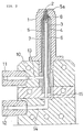
- a nozzle body indicated at 1 with an injection opening 2 formed in the central portion in the end surface thereof is interiorly provided a first resin path 3, a second resin path 4 and a third resin path 5 in a concentric fashion.
- Each of the resin paths is formed with a first hollow core member 6 and a second hollow core member 7 having a spacer on the side thereof, which inserted from the opening at the rear end of the nozzle body 1 into the nozzle body in order.
- a three-layer nozzle shown in FIG. 1 has a construction in which a mouth portion 3a of the first resin path 3 connected to the injection opening 2 is internally provided with a mouth portion 4a of the second resin path 4,and a mouth portion 4a of the second resin path 4 is internally provided with a mouth portion 5a of the third resin path 5, the mouth portion 5a being formed from a valve member 8.
- the aforesaid valve member 8 comprises an annular body which is inserted so as to appear in the inner side of the end of the second core member 7.
- the inside diameter of the valve member 8 is substantially equal to the inside diameter of the mouth portion of the first resin path 3 and is smaller than the diameter of the third resin path 5, and the fore end 8a and the rear end 8b thereof are formed into a tapered surface on which resin pressure exerts.
- the ratio of a pressure receiving area between both the ends 8a and 8b is preferably in the range of
- valve member 8 is operated to open and close the second resin path 4 according to a difference between the resin pressures exerting on both the ends to control the injection of the molten resin from the second resin path 4.
- a three-layer nozzle shown in FIG. 2 has a construction in which opening and closing of the second resin path 4 may be accomplished by the resin pressure of the first resin path 3, and the valve member is inserted to as to appear in the end of the first core member 6.
- the second resin path 4 is closed by the backward movement of the valve member 8, the end 7a of the second core member 7 is reduced in diameter, the end is extended frontwardly of the first resin path 3, the mouth portion 5a of the third resin path is made to front on the inner side of the mouth portion 3a, the second resin path 4 is opened at the side of the end portion, and the mouth portion 41 is constituted by the valve member 8 in the periphery of the end of the second core member 7 inserted into the end of the first core member 6.
- the inside diameter of the valve member 8 is larger than the outside diameter of the end portion of the second core member 7 to form a part of the second resin path 4 between it and the second core member 7, and when the rear end 8b comes into contact with a tapered shoulder 9 formed in the outer surface of the second core memebr 7, the second resin path 4 is closed.
- the ratio of a pressure receiving area between the fore end 8a and the rear end 8b of the valve member 8 formed into a tapered surface is preferably in the range of 0.5 ⁇ second resin path / first resin path ⁇ 4 in the projection plane.
- Resins as material supplied to the respective resin paths are suitably selected depending on molded products, and in case of 3-kinds and 5-layers, different resins are supplied to the respective resin paths.
- the resin material of the first resin path 3 is the same kind as that of the third resin path 5.
- the required number of the aforesaid three-layer nozzles are used while being mounted on a hot runner block 10.
- This embodiment shows the case where a 2-kind and 3-layer molded product is molded, in which the hot runner block 10 is interiorly provided with hot runners 13 and 41 connected to sprue bushes 11 and 12, respectively, arranged on the side thereof, and the hot runner 13, the hot runner 14 and a branch path 15 of the hot runner 14 are connected to the second resin path 4, the third resin path 5 and the first resin path 3, respectively, so that the same kind of resins can be injection from the first and third resin paths 3 and 5, and the different resins from the second resin path 4.
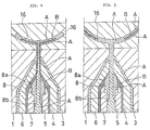
- the valve member 8 is moved backward, as shown in FIG. 4, due to a difference in a pressure receiving area in the valve member 8, to open the second resin path 4 so that the molten resin B is cut in and between the molten resins A and A from the first and third resin paths 3 and 5 and flows out and is then injected into the cavity 16 together with the molten resins A and A from the injection opening 2.
- the molten resin B injected from the second resin path 4 is to be positioned in the center between the molten resins A and A, and therefore, when the resin is filled and moved in the cavity, even if a skin layer caused by cooling should occur on the surfaces of the molten resins A and A in contact with the mold surface, the skin layer slowly influences thereon and the molten resin B is hard to form a skin layer halfway.
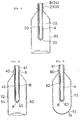
- a molded product 20 shown in FIG. 6 is a preform having a bottom comprising a three-layer of a mouth portion 21 alone obained by injecting and filling the molten resin B of the second resin path 4 and a single layer of a body 22 and a bottom 23 obtained by only the molten resin A, the chain line indicating a container 30 in which a preform having a bottom is orientation blow molded.
- a molded product 40 shown in FIG. 7 is a preform having a bottom comprising a three-layer obtained by injecting and filling the molten resin B of the second resin path 4 into a body 42 alone and a single layer of a mouth portion 41 and a bottom 43 merely filled with the molten resin A, the chain line indicating a container 50 in which a preform having a bottom is orientation blow molded.
- a molded product 60 shown in FIG. 8 is a preform having a bottom comprising a three-layer obtained by injecting and filling the molten resin B of the second resin path 4 into a bottom 63 alone and a single layer of a mouth portion 61 and a body 62 merely filled with the molten resin A, the chain line indicating a container 70 in which a preform having a bottom is orientation blow molded.
- the resin used as the molten resin A may comprise a resin such as a polyethylene terephthalate, and the molten resin B includes resins excellent in barrier properties such as methaxylene group contained polyamide, ethylene vinyl alcohol and high nitrile or resins having a heat resistance such aspolycarbonate and U-polymer, which are used according to uses of containers molded thereby.
- a resin such as a polyethylene terephthalate
- the molten resin B includes resins excellent in barrier properties such as methaxylene group contained polyamide, ethylene vinyl alcohol and high nitrile or resins having a heat resistance such aspolycarbonate and U-polymer, which are used according to uses of containers molded thereby.
- a resin forming an intermediate laye 34 comprises a polycarbonate
- formation of a mouth portion 31 of a container 30 into a multi-layer remarkably improves a heat resistance as compared with the case where it merely comprises a polyethylene terephthalate to prevent the mouth portion from being changed during heating and filling.
- barrier properties are improved, peeling between between layers when a bottom is formed into a multi-layer can be prevented, and expensive resins used for the intermediate layer 54 can be saved.
- a first, a second and a third resin paths are concentrically provided within a nozzle body, the second resin path being closed by a valve member which is actuated by resin pressure of the other resin paths to control a molten resin from the second resin path, whereby a position at which an intermediate layer is formed by the molten resin can be suitably set. Therefore, only the mouth portion, body or bottom of a molded product can be formed into a multilayer. Since the position of the intermediate layer can be set to a central portion, in injection molding of a multi-layer molded product, the effect is great, and it is industrially very effective and widely utilized.
Abstract
Description
- This invention relates to a multi-layer molding nozzle used when a synthetic resin molded product whose sectional construction has a multilayer is injection molded.
- A conventional multi-layer molding nozzle comprises a multiple nozzle in which a nozzle body having a mouth portion in a central portion at a tip thereof is interiorly provided with a plurality of resin paths in a concentric fashion, and different molten resins in the respective resin paths can be cavity-injected from said mouth of the nozzle.
- Formation of a synthetic resin molded product into a mulit-layer causes a quality of a thin-wall molded product as a beverage container to be further improved by the resin present as an intermediate layer. However, this poses a problem in that because of the provision of an intermediate layer, shock resistance of the product is lowered or the cost of the product increases, as compared with those of a single layer.
- In view of the foregoing, an attempt has been made so that a conventional double or three-layer nozzle is used to control injection pressure, time, injection timing or the like of the molten resin which forms an intermediate layer so as to injection-mold a product partly having an intermediate layer. However, it has been very difficult to mold an intermedite layer within a predetermined range in terms of resin pressure.
- Alternatively, there is a multiple nozzle in which a central path of a multiple resin path is made movable so that orifices of resin paths are selectively opened and closed to control molten resin, as disclosed in Japanese Patent Application Laid-Open No. 60-34819. However, in this case, a special valve device is required to control a flow of molten resin entering the central path passing through the orifice for injection, and in addition, the valve device is mechanically operated, and the nozzle has an extremely complicated construction.
- This invention has been achieved in order to solve the above-described problems with respect to the conventional multiple nozzle. An object of this invention is to provide a new multi-layer molding nozzle which is simple in construction, and in which a flowpassage of molten resin which is to form an intermedite layer is opened and closed by a valve member to be operated by resin pressure to always accurately switch a multiple layer to a single layer and vice versa.
- This invention having the aforesaid object overcomes the aforementioned problem encountered in the prior art by a three-layer nozzle in which a nozzle body is interiorly provided with a first resin path, a second resin path and a third resin path having the same injection opening in a concentric fashion, in which multiple nozzle, a mouth portion of the central third resin path located internally of a mouth portion of the second resin path is constituted by a valve member which is moved forward and backward by resin pressure of the third resin path and the second resin path to open and close the second resin path, and a mouth portion of the intermedite second resin path located internally of the first resin path is constituted by a valve member which is moved forward and backward by resin pressure of the second resin path and the first resin path to open and close the second resin path.
- In the above-described structure, the moten resins of the respective resin paths applied with injection pressure are simultaneously injected from the mouth portion of the respective resin paths to cavities through the mouth portion of the nozzle. When the injection pressure of the second resin path is removed during the injection, the valve member is moved forward or backward by the resin pressure of the first or third resin path to close the second resin path to stop an outflow of the molten resin from the second resin path. Because of this, the molten resins of the first and third resin paths are merely injected to the cavity.
- When injection pressure is applied to the second resin path, the valve member is moved backward or forward due to a difference in pressure receiving area in the valve member to open the second resin path, and the molten resin is injected to the cavity together with the molten resin of the other resin paths.
- Accordingly, when the same kind of molten resin is used for the first and third resin paths and the different kind of molten resin is used for the second resin path, a molded product produced thereat is composed of a 2-kind 3-layer portion and a single layer portion.
- This invention will be further described in detail by way of examples shown in the drawings.
- The drawings show embodiments of a multi-layer molding nozzle according to this invention in which: FIG. 1 is a sectional view of a first embodiment; FIG. 2 is a sectional view of a second embodiment thereof; FIG. 3 is a sectional view in which a hot runner block is mounted; FIGS. 4 and 5 are respectively sectional views showing the molding steps; and FIGS. 6 to 8 are respectively sectional view of a preform having a bottom and a container.
- A nozzle body indicated at 1 with an
injection opening 2 formed in the central portion in the end surface thereof is interiorly provided afirst resin path 3, asecond resin path 4 and athird resin path 5 in a concentric fashion. - Each of the resin paths is formed with a first
hollow core member 6 and a secondhollow core member 7 having a spacer on the side thereof, which inserted from the opening at the rear end of thenozzle body 1 into the nozzle body in order. - A three-layer nozzle shown in FIG. 1 has a construction in which a
mouth portion 3a of thefirst resin path 3 connected to theinjection opening 2 is internally provided with amouth portion 4a of thesecond resin path 4,and amouth portion 4a of thesecond resin path 4 is internally provided with amouth portion 5a of thethird resin path 5, themouth portion 5a being formed from avalve member 8. - The
aforesaid valve member 8 comprises an annular body which is inserted so as to appear in the inner side of the end of thesecond core member 7. The inside diameter of thevalve member 8 is substantially equal to the inside diameter of the mouth portion of thefirst resin path 3 and is smaller than the diameter of thethird resin path 5, and thefore end 8a and therear end 8b thereof are formed into a tapered surface on which resin pressure exerts. - The ratio of a pressure receiving area between both the
ends - 0.5 < second resin path / third resin path < 4 in the projection plane, and as long as the aforementioned relevant formula is satisfied, even if the resin pressure of the
third resin path 5 is being applied to therear end 8b by the resin pressure of thesecond resin path 4 during the injection, thevalve member 8 is moved into the end of thesecond core member 7 to maintain thesecond resin 4 open but when the injection pressure of thesecond resin path 4 is controlled to remarkably lower the resin pressure, thevalve member 8 is immediately moved forward due to the resin pressure of thethird resin path 5 exerting on therear end 8b to close thesecond resin path 4. - Accordingly, the
valve member 8 is operated to open and close thesecond resin path 4 according to a difference between the resin pressures exerting on both the ends to control the injection of the molten resin from thesecond resin path 4. - A three-layer nozzle shown in FIG. 2 has a construction in which opening and closing of the
second resin path 4 may be accomplished by the resin pressure of thefirst resin path 3, and the valve member is inserted to as to appear in the end of thefirst core member 6. - In this case, since the
second resin path 4 is closed by the backward movement of thevalve member 8, theend 7a of thesecond core member 7 is reduced in diameter, the end is extended frontwardly of thefirst resin path 3, themouth portion 5a of the third resin path is made to front on the inner side of themouth portion 3a, thesecond resin path 4 is opened at the side of the end portion, and themouth portion 41 is constituted by thevalve member 8 in the periphery of the end of thesecond core member 7 inserted into the end of thefirst core member 6. The inside diameter of thevalve member 8 is larger than the outside diameter of the end portion of thesecond core member 7 to form a part of thesecond resin path 4 between it and thesecond core member 7, and when therear end 8b comes into contact with atapered shoulder 9 formed in the outer surface of thesecond core memebr 7, thesecond resin path 4 is closed. - The ratio of a pressure receiving area between the
fore end 8a and therear end 8b of thevalve member 8 formed into a tapered surface is preferably in the range of 0.5 < second resin path / first resin path < 4 in the projection plane. - Resins as material supplied to the respective resin paths are suitably selected depending on molded products, and in case of 3-kinds and 5-layers, different resins are supplied to the respective resin paths. In the case where a product having 2-kinds and 3-layers is injection molded, the resin material of the
first resin path 3 is the same kind as that of thethird resin path 5. - The required number of the aforesaid three-layer nozzles are used while being mounted on a
hot runner block 10. This embodiment shows the case where a 2-kind and 3-layer molded product is molded, in which thehot runner block 10 is interiorly provided withhot runners sprue bushes hot runner 13, thehot runner 14 and abranch path 15 of thehot runner 14 are connected to thesecond resin path 4, thethird resin path 5 and thefirst resin path 3, respectively, so that the same kind of resins can be injection from the first andthird resin paths second resin path 4. - Next, molding of a three-layer molded product having an intermediate layer by use of the three-layer nozzle shown in FIG. 1 will be described hereinafter.
- First, when injection pressure is applied to the first and
third resin paths valve member 8 together with the molten resins is moved forward simultaneously with the injection due to a pressure difference between thesecond resin path 4 and thethird resin path 5 to close thesecond resin path 4 as shown in FIG. 4. - Thereby, only the same molten resins A and A are injected to a
cavity 16, and different molten resin B of thesecond resin path 4 will not be injected. - Subsequently, at the time of completion of the injection of a predetermined quantity of molten resins A and A and when injection pressure is applied to the
second resin path 4 while continuing the aforesaid injection, thevalve member 8 is moved backward, as shown in FIG. 4, due to a difference in a pressure receiving area in thevalve member 8, to open thesecond resin path 4 so that the molten resin B is cut in and between the molten resins A and A from the first andthird resin paths cavity 16 together with the molten resins A and A from theinjection opening 2. - After the aforesaid injection has been completed, a product having three layers as a whole is molded, and when injection pressure of the
second resin path 4 is disconnected, thevalve member 6 is again moved forward by the resin pressure of thethird resin path 5, as shown in FIG. 5, due to a difference in resin pressure at that time, to close thesecond resin path 4. - Therefore, only the same molten resins A and A are again injected halfway, and a single layer is molded. The molten resin B injected from the
second resin path 4 is to be positioned in the center between the molten resins A and A, and therefore, when the resin is filled and moved in the cavity, even if a skin layer caused by cooling should occur on the surfaces of the molten resins A and A in contact with the mold surface, the skin layer slowly influences thereon and the molten resin B is hard to form a skin layer halfway. - A molded
product 20 shown in FIG. 6 is a preform having a bottom comprising a three-layer of amouth portion 21 alone obained by injecting and filling the molten resin B of thesecond resin path 4 and a single layer of abody 22 and abottom 23 obtained by only the molten resin A, the chain line indicating acontainer 30 in which a preform having a bottom is orientation blow molded. - A molded
product 40 shown in FIG. 7 is a preform having a bottom comprising a three-layer obtained by injecting and filling the molten resin B of thesecond resin path 4 into abody 42 alone and a single layer of amouth portion 41 and abottom 43 merely filled with the molten resin A, the chain line indicating acontainer 50 in which a preform having a bottom is orientation blow molded. - A molded
product 60 shown in FIG. 8 is a preform having a bottom comprising a three-layer obtained by injecting and filling the molten resin B of thesecond resin path 4 into abottom 63 alone and a single layer of amouth portion 61 and abody 62 merely filled with the molten resin A, the chain line indicating acontainer 70 in which a preform having a bottom is orientation blow molded. - The resin used as the molten resin A may comprise a resin such as a polyethylene terephthalate, and the molten resin B includes resins excellent in barrier properties such as methaxylene group contained polyamide, ethylene vinyl alcohol and high nitrile or resins having a heat resistance such aspolycarbonate and U-polymer, which are used according to uses of containers molded thereby.
- For example, when a resin forming an
intermediate laye 34 comprises a polycarbonate, formation of amouth portion 31 of acontainer 30 into a multi-layer remarkably improves a heat resistance as compared with the case where it merely comprises a polyethylene terephthalate to prevent the mouth portion from being changed during heating and filling. - Similarly, when a
bottom 73 of a container 70 (FIG. 8) is formed into a multi-layer by an intermediate layer 78 of U-polyer, the heat resistance of thebottom 73 is improved, and even if heat treatment is conducted after filling a carbonated juice, a central portion thereof is not projected and deformed as in a bottom of a single layer. - Furthermore, in a product in which only a
body 52 is formed into a multi-layer by an intermediate layer formed of a methaxylene group contained polyamide, barrier properties are improved, peeling between between layers when a bottom is formed into a multi-layer can be prevented, and expensive resins used for the intermediate layer 54 can be saved. - Next, one example of molding conditions in the case of the three-layer nozzle shown in FIG. 1 is given below.
- o Sectional area of resin paths

- o Diameter of injection opening 2.0 to 3.0 mm
- o Pressure receiving area (projection area) of valve member Second resin path side (fore end) 25.13 mm 2 Third resin path side (rear end) 21.23 mm 2
- o Resin material First and third resin paths Polyethylene terephthalate Second resin path SM nylon
- o Injection pressure First and third resin paths

- As mentioned above, according to this invention, a first, a second and a third resin paths are concentrically provided within a nozzle body, the second resin path being closed by a valve member which is actuated by resin pressure of the other resin paths to control a molten resin from the second resin path, whereby a position at which an intermediate layer is formed by the molten resin can be suitably set. Therefore, only the mouth portion, body or bottom of a molded product can be formed into a multilayer. Since the position of the intermediate layer can be set to a central portion, in injection molding of a multi-layer molded product, the effect is great, and it is industrially very effective and widely utilized.
Claims (5)
- (1) In a three-layer nozzle in which a first resin path, a second resin path and a third resin path having the same injection opening are formed in the form of a concentric circle by a first core member and a second core member disposed interiorly of a nozzle body, a multi-layer forming nozzle characterized in that a mouth portion of the third resin path in the central portion positioned internally of the mouth portion of the second resin path is constituted by a valve member which is moved forward and backward by resin pressure of the third resin path and the second resin path to open and close the second resin path.
- (2) In a three-layer nozzle in which a first resin path, a second resin path and a third resin path having the same injection opening are formed in the form of a concentric circle by a first core member and a second core member disposed interiorly of a nozzle body, a multi-layer forming nozzle characterized in that a mouth portion of the second resin path in the intermediate portion positioned internally of the first resin path is constituted by a valve member which is moved forward and backward by resin pressure of the second resin path and the first resin path to open and close the second resin path.
- (3) A multi-layer forming nozzle according to Claim 2, wherein an end portion of said second core member is reduced in diameter and an end thereof is extended to the first resin path, a mouth portion of the third resin path is made to front an aninner side of the mouth portion, the second resin path being opened at the side of the end portion, said mouth portion being constituted by a valve member in the periphery of the end portion of the first core member, said valve member being inserted into the end of the first core member, and the rear end of the valve member comes into a tapered shoulder formed on the outer side of the second core member to close the second resin path.
- (4) A multi-layer forming nozzle according to Claim 1, wherein said valve member comprises an annular body fitted so as to appear in an inner side of the end portion of the second core member, said valve having its inside diameter substantially equal to the inside diameter of the mouth portion of the first resin path but smaller than the diameter of the third resin path, the fore.end and rear end thereof being formed into a tapered surface, and the ratio between pressure receiving areas of the both the ends is in the range of0.5 < second resin path / third resin path < 4 in the projection plane.
- (5) A multi-layer forming nozzle according to Claim 2 and 3, wherein said valve member comprises an annular body fitted so as to appear in aninner side of the end portion of the first core member, said valve having its inside diameter formed to be larger than the outside diameter of the end portion of the second core member to form a part of the second resin path between it and the second core member, and the ratio between pressure receiving';areas of the fore end and the rear end of the valve member formed into a tapered surface is in the range of0.5 < second resin path / first resin path < 4 in the projection plane.
Applications Claiming Priority (1)
| Application Number | Priority Date | Filing Date | Title |
|---|---|---|---|
| PCT/JP1987/000841 WO1989003756A1 (en) | 1987-10-30 | 1987-10-30 | Multilayer forming nozzle |
Publications (3)
| Publication Number | Publication Date |
|---|---|
| EP0374247A4 EP0374247A4 (en) | 1989-11-07 |
| EP0374247A1 true EP0374247A1 (en) | 1990-06-27 |
| EP0374247B1 EP0374247B1 (en) | 1994-11-17 |
Family
ID=13902898
Family Applications (1)
| Application Number | Title | Priority Date | Filing Date |
|---|---|---|---|
| EP87907143A Expired - Lifetime EP0374247B1 (en) | 1987-10-30 | 1987-10-30 | Multilayer forming nozzle |
Country Status (7)
| Country | Link |
|---|---|
| US (1) | US5030077A (en) |
| EP (1) | EP0374247B1 (en) |
| KR (1) | KR950012854B1 (en) |
| AU (1) | AU604278B2 (en) |
| DE (1) | DE3750765T2 (en) |
| RU (1) | RU1838120C (en) |
| WO (1) | WO1989003756A1 (en) |
Cited By (14)
| Publication number | Priority date | Publication date | Assignee | Title |
|---|---|---|---|---|
| EP0467274A2 (en) * | 1990-07-16 | 1992-01-22 | Nissei Asb Machine Co., Ltd. | Multi-ply molding hot-runner mold |
| EP0748677A1 (en) * | 1995-06-14 | 1996-12-18 | Krauss-Maffei Aktiengesellschaft | Injection moulding apparatus |
| DE19606045A1 (en) * | 1996-02-19 | 1997-08-21 | Krupp Ag Hoesch Krupp | Process for the injection molding of three-layer moldings and device for carrying out the process |
| DE19617349C1 (en) * | 1996-04-30 | 1997-09-04 | Hans Kuehn | Injection moulding of multilayered tubing |
| DE19613779A1 (en) * | 1996-04-04 | 1997-10-09 | Krupp Ag Hoesch Krupp | Process for the injection molding of three-layer moldings and device for carrying out the process |
| EP0887169A1 (en) * | 1997-06-27 | 1998-12-30 | Altoplast AG | Method for producing a multilayer preform and preform produced according to the method |
| EP0911135A2 (en) * | 1997-10-23 | 1999-04-28 | Mold-Masters Limited | Injection molding apparatus having a melt bore through the front end of the pin |
| WO2000027609A1 (en) * | 1998-11-05 | 2000-05-18 | Gellert Jobst U | Method of three layer injection molding with sequential and simultaneous coinjection |
| WO2000054956A1 (en) * | 1999-03-18 | 2000-09-21 | Mold-Masters Limited | Apparatus and method for multi-layer injection molding |
| US6440350B1 (en) | 1999-03-18 | 2002-08-27 | Mold-Masters Limited | Apparatus and method for multi-layer injection molding |
| WO2006099700A3 (en) * | 2005-03-25 | 2007-03-22 | Resilux | Device and process for manufacturing a preform, preform for blow moulding a container and such a container |
| EP1820621A2 (en) | 2006-02-17 | 2007-08-22 | LeadX Aktiengesellschaft | Device for manufacturing a tubular jacket charged with substances |
| US7399442B2 (en) | 2004-07-07 | 2008-07-15 | Kortec, Inc. | Multilayer molding using temperature adjustment of flow rate in conjunction with shooting pot technology |
| EP2054209B1 (en) * | 2006-08-26 | 2011-11-30 | MHT Mold & Hotrunner Technology AG | Method for the production of a multi-layer preform and nozzle therefor |
Families Citing this family (20)
| Publication number | Priority date | Publication date | Assignee | Title |
|---|---|---|---|---|
| US5131830A (en) * | 1987-10-30 | 1992-07-21 | Nissei Asb Machine Co., Ltd. | Multi-layer molding nozzle |
| US5156857A (en) * | 1988-11-23 | 1992-10-20 | American National Can Company | Extrusion die for extrusion blow molding equipment |
| NO171048C (en) * | 1989-12-19 | 1993-01-20 | Soennichsen As | LUBRICANTS FOR PLASTIC EXTRADERS |
| US5279781A (en) * | 1990-06-12 | 1994-01-18 | Tanaka Kikinzoku Kogyo K.K. | Melt-spin process for electroconductive fibers used in human-implantable electrode and cloth |
| US5369762A (en) * | 1990-06-28 | 1994-11-29 | Wolf; William M. | Method for sorting data in a computer at high speed by using data word values for address locations |
| US5198239A (en) * | 1991-07-08 | 1993-03-30 | Beavers Charles T | Apparatus for co-extruding two food products |
| JP2794268B2 (en) * | 1994-10-21 | 1998-09-03 | 日精樹脂工業株式会社 | Injection equipment for molding synthetic resin hollow bodies, foams, etc. |
| US5900260A (en) * | 1996-12-09 | 1999-05-04 | Cincinnati Milacron Inc. | Accumulator head having a segmented barrel |
| US5972258A (en) * | 1997-10-20 | 1999-10-26 | Husky Injection Molding Systems Ltd. | Method of using a multiple gating nozzle |
| CA2331132C (en) | 1998-05-01 | 2008-12-16 | Fei Enterprises, Ltd. | Method for injection molding manufacture of controlled release devices |
| US6398537B2 (en) | 1999-04-02 | 2002-06-04 | Mold-Masters Limited | Shuttle system for an apparatus for injection molding |
| US6196826B1 (en) | 1999-05-28 | 2001-03-06 | Mold-Masters Limited | Seepage system for an injection molding apparatus |
| US6706438B2 (en) * | 2000-08-10 | 2004-03-16 | Honda Giken Kogyo Kabushiki Kaisha | Fluid supply device for fuel cell |
| US7207796B2 (en) * | 2004-07-01 | 2007-04-24 | Husky Injection Moldiing Systems Ltd. | Hot runner coinjection nozzle with thermally separated melt channels |
| US20080093772A1 (en) * | 2006-10-06 | 2008-04-24 | Graham Packing Company, Lp | Method and apparatus for delivering sequential shots to multiple cavities to form multilayer articles |
| CA2622692C (en) * | 2007-02-26 | 2015-10-06 | Advanced Drainage Systems, Inc. | Defined ratio dual-wall pipe die |
| US9498911B2 (en) | 2010-09-21 | 2016-11-22 | Mold-Masters (2007) Limited | Coinjection hot runner injection molding system |
| EP3453511B1 (en) | 2010-09-21 | 2020-09-16 | Mold-Masters (2007) Limited | Coinjection hot runner injection molding system |
| US9073246B2 (en) | 2011-09-21 | 2015-07-07 | Mold-Masters (2007) Limited | Coinjection hot runner injection molding system |
| DE102014004221A1 (en) | 2014-03-25 | 2015-10-01 | Hpt Hochwertige Pharmatechnik Gmbh & Co. Kg | Spray station for the production of multilayer preforms |
Citations (3)
| Publication number | Priority date | Publication date | Assignee | Title |
|---|---|---|---|---|
| FR1290262A (en) * | 1961-03-01 | 1962-04-13 | Improvements to injection machines for plastics | |
| US4052497A (en) * | 1973-09-21 | 1977-10-04 | Billion S.A. | Method of injection-moulding by injection of an article composed of at least three different materials |
| DE3305931A1 (en) * | 1983-02-21 | 1984-08-23 | Battenfeld Maschfab | Apparatus for discontinuously producing multilayer mouldings from plastic |
Family Cites Families (9)
| Publication number | Priority date | Publication date | Assignee | Title |
|---|---|---|---|---|
| JPS5223160A (en) * | 1975-08-15 | 1977-02-21 | Asahi Dow Ltd | Device for injection molding sandwich structure |
| US4190409A (en) * | 1977-10-14 | 1980-02-26 | Karl Hehl | Apparatus for injecting confluent streams of plastic |
| JPS5650700A (en) * | 1979-09-06 | 1981-05-07 | Cbs Inc | Sound reproducer using acoustic processor |
| US4511528A (en) * | 1983-04-13 | 1985-04-16 | American Can Company | Flow stream channel splitter devices for multi-coinjection nozzle injection molding machines |
| JPS60179418U (en) * | 1984-05-09 | 1985-11-28 | 日精エー・エス・ビー機械株式会社 | Hot runner mold for three-layer molding |
| US4657496A (en) * | 1984-06-04 | 1987-04-14 | Gifu Husky Co., Ltd. | Hot-runner mold for injection molding |
| AU4558685A (en) * | 1984-07-31 | 1986-02-06 | Nissei Asb Machine Co., Ltd. | Multi-layer parison |
| JPS61274912A (en) * | 1985-05-31 | 1986-12-05 | Nissei Ee S B Kikai Kk | Nozzle apparatus for multilayer molding |
| US4863665A (en) * | 1987-05-18 | 1989-09-05 | Husky Injection Molding Systems, Ltd. | Tri-injection of hollow articles |
-
1987
- 1987-10-30 EP EP87907143A patent/EP0374247B1/en not_active Expired - Lifetime
- 1987-10-30 KR KR1019890701181A patent/KR950012854B1/en not_active IP Right Cessation
- 1987-10-30 AU AU81565/87A patent/AU604278B2/en not_active Expired
- 1987-10-30 DE DE3750765T patent/DE3750765T2/en not_active Expired - Lifetime
- 1987-10-30 US US07/381,650 patent/US5030077A/en not_active Expired - Lifetime
- 1987-10-30 WO PCT/JP1987/000841 patent/WO1989003756A1/en active IP Right Grant
-
1989
- 1989-06-30 RU SU894614754A patent/RU1838120C/en active
Patent Citations (3)
| Publication number | Priority date | Publication date | Assignee | Title |
|---|---|---|---|---|
| FR1290262A (en) * | 1961-03-01 | 1962-04-13 | Improvements to injection machines for plastics | |
| US4052497A (en) * | 1973-09-21 | 1977-10-04 | Billion S.A. | Method of injection-moulding by injection of an article composed of at least three different materials |
| DE3305931A1 (en) * | 1983-02-21 | 1984-08-23 | Battenfeld Maschfab | Apparatus for discontinuously producing multilayer mouldings from plastic |
Non-Patent Citations (2)
| Title |
|---|
| PLASTVERARBEITER, vol. 28, no. 11, November 1977, page 609, Speyer/Rhein, DE; "Zwei-Komponenten-Spritzgussmaschinen mit grosser Zukunft" * |
| See also references of WO8903756A1 * |
Cited By (22)
| Publication number | Priority date | Publication date | Assignee | Title |
|---|---|---|---|---|
| EP0467274A2 (en) * | 1990-07-16 | 1992-01-22 | Nissei Asb Machine Co., Ltd. | Multi-ply molding hot-runner mold |
| EP0467274A3 (en) * | 1990-07-16 | 1992-05-20 | Nissei Asb Machine Co., Ltd. | Multi-ply molding hot-runner mold |
| US5232710A (en) * | 1990-07-16 | 1993-08-03 | Nissei Asb Machine Co., Ltd. | Multi-ply molding hot-runner mold |
| EP0748677A1 (en) * | 1995-06-14 | 1996-12-18 | Krauss-Maffei Aktiengesellschaft | Injection moulding apparatus |
| DE19606045A1 (en) * | 1996-02-19 | 1997-08-21 | Krupp Ag Hoesch Krupp | Process for the injection molding of three-layer moldings and device for carrying out the process |
| DE19613779A1 (en) * | 1996-04-04 | 1997-10-09 | Krupp Ag Hoesch Krupp | Process for the injection molding of three-layer moldings and device for carrying out the process |
| DE19613779C2 (en) * | 1996-04-04 | 1998-07-16 | Krupp Ag Hoesch Krupp | Process for the injection molding of three-layer moldings and device for carrying out the process |
| DE19617349C1 (en) * | 1996-04-30 | 1997-09-04 | Hans Kuehn | Injection moulding of multilayered tubing |
| US6702978B1 (en) | 1996-04-30 | 2004-03-09 | Hans Kuehn | Process for manufacturing a plastic tube body |
| EP0887169A1 (en) * | 1997-06-27 | 1998-12-30 | Altoplast AG | Method for producing a multilayer preform and preform produced according to the method |
| EP0911135A3 (en) * | 1997-10-23 | 2000-03-08 | Mold-Masters Limited | Injection molding apparatus having a melt bore through the front end of the pin |
| EP0911135A2 (en) * | 1997-10-23 | 1999-04-28 | Mold-Masters Limited | Injection molding apparatus having a melt bore through the front end of the pin |
| WO2000027609A1 (en) * | 1998-11-05 | 2000-05-18 | Gellert Jobst U | Method of three layer injection molding with sequential and simultaneous coinjection |
| CN1104319C (en) * | 1998-11-05 | 2003-04-02 | 乔布斯特·乌尔里克·盖勒特 | Method of three layer injection molding with sequential and simultaneous coinjection |
| WO2000054956A1 (en) * | 1999-03-18 | 2000-09-21 | Mold-Masters Limited | Apparatus and method for multi-layer injection molding |
| US6440350B1 (en) | 1999-03-18 | 2002-08-27 | Mold-Masters Limited | Apparatus and method for multi-layer injection molding |
| US6648622B1 (en) | 1999-03-18 | 2003-11-18 | Mold Masters Limited | Apparatus and method for multi-layer injection molding |
| US7399442B2 (en) | 2004-07-07 | 2008-07-15 | Kortec, Inc. | Multilayer molding using temperature adjustment of flow rate in conjunction with shooting pot technology |
| WO2006099700A3 (en) * | 2005-03-25 | 2007-03-22 | Resilux | Device and process for manufacturing a preform, preform for blow moulding a container and such a container |
| EP1820621A2 (en) | 2006-02-17 | 2007-08-22 | LeadX Aktiengesellschaft | Device for manufacturing a tubular jacket charged with substances |
| DE102006007482B4 (en) * | 2006-02-17 | 2014-06-18 | Leadx Ag | Apparatus and method for producing a tubular enclosure |
| EP2054209B1 (en) * | 2006-08-26 | 2011-11-30 | MHT Mold & Hotrunner Technology AG | Method for the production of a multi-layer preform and nozzle therefor |
Also Published As
| Publication number | Publication date |
|---|---|
| EP0374247A4 (en) | 1989-11-07 |
| AU604278B2 (en) | 1990-12-13 |
| DE3750765T2 (en) | 1995-06-22 |
| WO1989003756A1 (en) | 1989-05-05 |
| RU1838120C (en) | 1993-08-30 |
| KR950012854B1 (en) | 1995-10-23 |
| EP0374247B1 (en) | 1994-11-17 |
| US5030077A (en) | 1991-07-09 |
| DE3750765D1 (en) | 1994-12-22 |
| AU8156587A (en) | 1989-05-23 |
| KR890701313A (en) | 1989-12-20 |
Similar Documents
| Publication | Publication Date | Title |
|---|---|---|
| EP0374247A1 (en) | Multilayer forming nozzle | |
| US5131830A (en) | Multi-layer molding nozzle | |
| EP0825008B2 (en) | Improved hot runner valve gate for eliminating unidirectional molecular orientation and weld lines from solidified resin used for forming molded articles | |
| KR900011553A (en) | Apparatus and method for injection molding multilayer preforms | |
| US5141695A (en) | Injection molding method for multi-layer bottomed parisons | |
| EP0367123B1 (en) | Multi-layer preform, method of forming preform, and container formed from the preform | |
| US5049345A (en) | Method of forming a multi-layer preform | |
| EP2772341B1 (en) | Process for injection molding a preform | |
| US5972258A (en) | Method of using a multiple gating nozzle | |
| US6634877B2 (en) | Apparatus for injection molding over-molded articles | |
| US4201209A (en) | Molded hypodermic plunger with integral shaft and elastomeric head | |
| US5840231A (en) | Valve gate assembly | |
| GB2118894A (en) | Method of making multi-layer injection molded articles | |
| CA2219257C (en) | Sprue gated five layer injection molding apparatus | |
| JP2929617B2 (en) | Method for producing cylindrical molded body | |
| JPH0698640B2 (en) | Multilayer molding nozzle | |
| CA2216065C (en) | An improved hot runner valve gate and method for eliminating unidirectional molecular orientation and weld lines from solidified resin used for forming molded articles | |
| JP2511390B2 (en) | Tube container molding method |
Legal Events
| Date | Code | Title | Description |
|---|---|---|---|
| PUAI | Public reference made under article 153(3) epc to a published international application that has entered the european phase |
Free format text: ORIGINAL CODE: 0009012 |
|
| 17P | Request for examination filed |
Effective date: 19891012 |
|
| AK | Designated contracting states |
Kind code of ref document: A1 Designated state(s): BE CH DE FR GB IT LI NL SE |
|
| RAP1 | Party data changed (applicant data changed or rights of an application transferred) |
Owner name: NISSEI ASB MACHINE CO., LTD. |
|
| 17Q | First examination report despatched |
Effective date: 19920304 |
|
| GRAA | (expected) grant |
Free format text: ORIGINAL CODE: 0009210 |
|
| ITF | It: translation for a ep patent filed |
Owner name: CON LOR S.R.L. |
|
| AK | Designated contracting states |
Kind code of ref document: B1 Designated state(s): BE CH DE FR GB IT LI NL SE |
|
| PG25 | Lapsed in a contracting state [announced via postgrant information from national office to epo] |
Ref country code: CH Effective date: 19941117 Ref country code: BE Effective date: 19941117 Ref country code: LI Effective date: 19941117 Ref country code: NL Effective date: 19941117 |
|
| REF | Corresponds to: |
Ref document number: 3750765 Country of ref document: DE Date of ref document: 19941222 |
|
| ET | Fr: translation filed | ||
| PG25 | Lapsed in a contracting state [announced via postgrant information from national office to epo] |
Ref country code: SE Effective date: 19950217 |
|
| REG | Reference to a national code |
Ref country code: CH Ref legal event code: PL |
|
| NLV1 | Nl: lapsed or annulled due to failure to fulfill the requirements of art. 29p and 29m of the patents act | ||
| PLBE | No opposition filed within time limit |
Free format text: ORIGINAL CODE: 0009261 |
|
| STAA | Information on the status of an ep patent application or granted ep patent |
Free format text: STATUS: NO OPPOSITION FILED WITHIN TIME LIMIT |
|
| 26N | No opposition filed | ||
| REG | Reference to a national code |
Ref country code: GB Ref legal event code: IF02 |
|
| PGFP | Annual fee paid to national office [announced via postgrant information from national office to epo] |
Ref country code: GB Payment date: 20061025 Year of fee payment: 20 |
|
| PGFP | Annual fee paid to national office [announced via postgrant information from national office to epo] |
Ref country code: DE Payment date: 20061026 Year of fee payment: 20 |
|
| PGFP | Annual fee paid to national office [announced via postgrant information from national office to epo] |
Ref country code: IT Payment date: 20061031 Year of fee payment: 20 |
|
| REG | Reference to a national code |
Ref country code: GB Ref legal event code: PE20 |
|
| PG25 | Lapsed in a contracting state [announced via postgrant information from national office to epo] |
Ref country code: GB Free format text: LAPSE BECAUSE OF EXPIRATION OF PROTECTION Effective date: 20071029 |
|
| PGFP | Annual fee paid to national office [announced via postgrant information from national office to epo] |
Ref country code: FR Payment date: 20061010 Year of fee payment: 20 |