EP0372955A2 - Position indicating device for a digital computer - Google Patents
Position indicating device for a digital computer Download PDFInfo
- Publication number
- EP0372955A2 EP0372955A2 EP89312756A EP89312756A EP0372955A2 EP 0372955 A2 EP0372955 A2 EP 0372955A2 EP 89312756 A EP89312756 A EP 89312756A EP 89312756 A EP89312756 A EP 89312756A EP 0372955 A2 EP0372955 A2 EP 0372955A2
- Authority
- EP
- European Patent Office
- Prior art keywords
- keys
- signals
- input
- motion
- input signal
- Prior art date
- Legal status (The legal status is an assumption and is not a legal conclusion. Google has not performed a legal analysis and makes no representation as to the accuracy of the status listed.)
- Withdrawn
Links
Images

Classifications
-
- G—PHYSICS
- G06—COMPUTING; CALCULATING OR COUNTING
- G06F—ELECTRIC DIGITAL DATA PROCESSING
- G06F3/00—Input arrangements for transferring data to be processed into a form capable of being handled by the computer; Output arrangements for transferring data from processing unit to output unit, e.g. interface arrangements
- G06F3/01—Input arrangements or combined input and output arrangements for interaction between user and computer
- G06F3/03—Arrangements for converting the position or the displacement of a member into a coded form
- G06F3/033—Pointing devices displaced or positioned by the user, e.g. mice, trackballs, pens or joysticks; Accessories therefor
- G06F3/0354—Pointing devices displaced or positioned by the user, e.g. mice, trackballs, pens or joysticks; Accessories therefor with detection of 2D relative movements between the device, or an operating part thereof, and a plane or surface, e.g. 2D mice, trackballs, pens or pucks
- G06F3/03543—Mice or pucks
-
- G—PHYSICS
- G06—COMPUTING; CALCULATING OR COUNTING
- G06F—ELECTRIC DIGITAL DATA PROCESSING
- G06F2203/00—Indexing scheme relating to G06F3/00 - G06F3/048
- G06F2203/033—Indexing scheme relating to G06F3/033
- G06F2203/0333—Ergonomic shaped mouse for one hand
Abstract
Description
- The present invention relates to an input device for use with a digital computer having a video display and more particularly for displaying the position of an indicator thereon.
- Input devices to a digital computer are well known in the art. One type of input device is the so-called "mouse" wherein movement of the mouse causes a position indicator on a video display connected to the digital computer to move in the same direction and magnitude. Typically, a mouse comprises a pair of transducers which detect the movement of the mouse in two orthogonal directions and supplies those signals to the digital computer. In addition, a mouse usually has two or three keys which can be activated and whose signals are also supplied to the digital computer.
- One of the shortcomings of the prior art mouse is that a mouse cannot be used to enter data, i.e. text or numbers. Further, the prior art mouse can be used to only issue a minimal number of commands. Because the mouse has only two or three keys, commands are entered by clicking, double clicking, or even triple clicking the keys on the mouse. This results in a maximum of nine types of different commands.
- Another problem with prior art mouse is that many programs are written to display commands which are displayed on the periphery of the display device. In order to activate these commands, the mouse must be physically moved to cause the position indicator to be positioned over the commands thereby activating the commands. Once the command has been executed, the mouse must be moved back to the original position if the user wishes to continue at the original position.
- Finally, although prior art mouses provided the capability for the user to reprogram the function of the mouse keys, the user must use the keyboard keys to reprogram the functions of the keys on the mouse.
- In the present invention an improved position indicating device for use with a digital computer having a video display is disclosed. The video display displays the position of an indicator thereon. The input device has a first transducing means for generating a first motion signal in response to the input device moving in a first direction. The device also has a second transducing means for generating a second motion signal in response to the input device moving in a second direction which is substantially perpendicular to the first direction. Finally, the mouse has a plurality of keys which supply input signals to the input device.
- In one embodiment, the video display displays a plurality of commands which are positioned generally to the periphery of the display and can be activated by the indicator being positioned thereon. The position indicating device further comprises means for receiving an input signal which is caused by the activation of one of the plurality of keys and activates one or more of the plurality of commands without the device and the indicator on the display being moved.
- In another embodiment, the improvement to the position indicating device comprises means which receives an input signal caused by the activation of one of the plurality of keys and causes the suspension and resumption in the transfer of the one or more motion signals to the computer in response thereto.
- In yet another embodiment, the improvement to the position indicating device comprises means which receives an input signal and reprograms the function of the plurality of keys in response to the input signal.
- Finally, in yet still another embodiment, the improvement to the position indicating device comprises means for processing the first and second motion signals and the input signal by supplying the input signals to the digital computer in the event the input signals are supplied to the input device. In the event no input signal is supplied to the position indicating device, the direction of motion of the device as represented by the first and second motion signal is determined and is supplied to the digital computer.
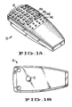
- Figure 1a is a perspective view of one embodiment of the improved input device of the present invention.
- Figure 1b is a bottom view of the improved input device shown in Figure 1a.
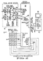
- Figure 2 is a schematic block diagram of one embodiment of a circuit incorporating the improved input device of the present invention for use with a digital computer and a video display.
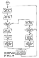
- Figure 3 is a flow diagram of an embodiment of a ROM control program which is resident in the improved input device of the present invention.
- Figure 4 is a flow diagram of an embodiment of a control program which is resident in the digital computer to which the improved input device of the present invention is connected.
- Referring to Figure 1 there is shown an improved
input device 10 of the present invention. The improvedinput device 10 comprises a rotatingmember 12 and a plurality ofkeys 14. The plurality ofkeys 14 include a numeric key pad 13 and a plurality of control keys 14(a-z). In one embodiment, there arefourty keys 14. - Referring to Figure 2 there is shown schematically a block level circuit diagram of the improved
input device 10 of the present invention. The rotatingmember 12 is rotatable in two mutually orthogonal directions: labelled as x-axis and y-axis. In the x-axis, the rotating member 12 (typically a ball) rotates a first wheel 16a having a plurality of slots. The first wheel 16a is interposed between a pair of first photodiodes 18a and a pair of first phototransistors 20a. Each turn of the first wheel 16a causing the interruption of the light from the pair of first photodiodes 18a to the pair of first phototransistors 20a causes a pair of pulses to be generated. The first wheel, turning in one direction, generates a pair of similar pulses. In the opposite direction of rotation, the pair of pulses comprises a pulse and its inverse. This is well known in the art. The pair of pulses are amplified by a pair of first amplifiers 22a and are designated as xr and xq and are supplied to the motionencoder input port 38 of acontrol microprocessor 30. - Similarly, in the y-axis motion, the rotation of the rotating
member 12 causes the rotation of thesecond wheel 16b. Like the first wheel 16a, thesecond wheel 16b is interposed between a pair ofsecond photodiodes 18b which generate light and is received by a corresponding pair of second phototransistors 20b. The signals from the pair of second phototransistors 20b are then amplified by the pair of second amplifiers 22b causing the generation of the pair of pulses which are supplied on the line labeled yr and yq to the motionencoder input port 38. - As previously stated, the generation of the pulses on the lines xr, xq, yr and yq is well known in the art and the generation of these signals are based upon conventional design. The motion signals xr, xq, yr and yq are supplied to the
control microprocessor 30, which in one embodiment, is a National Semiconductor part COPS820. - The plurality of
keys 14 are connected to a key switch matrix 24. The key switch matrix 24 has an output thereof which is a plurality oflines 26 supplied to thekey input port 34 of thecontrol microprocessor 30. Thecontrol microprocessor 30 also has a key scanmask output port 36 which supplies a plurality oflines 28 to the key switch matrix 24. The function of the key scanmask output port 36 is to generate signals thereon which are supplied to the key switch matrix 24 to determined if any of thekeys 14 have been depressed. This aspect of thedevice 10 to determine if any of thekeys 14 has been activated is also of well known conventional design. - The
control microprocessor 30 also has a second output port 32 which is connected viacable 40 to a hostdigital computer 42. Thedigital computer 42 has avideo display 50 for displaying the position of an indicator thereon. The function of the improvedinput device 10 is to indicate the position of the indicator on thevideo display 50. - In one embodiment, the
control microprocessor 30 has a control program which is stored in a Read Only Memory (ROM) 60. The function of theROM control program 60 is shown in a flow diagram form in Figure 3. TheROM control program 60 functions to operate thecontrol microprocessor 30. - Initially, the key scan
mask output port 36 is set such that all thelines 28 are activated to read all of thekeys 14. Thereafter, the keypress input port 34 is read to see if there is any signal from theinput lines 26. If anykey 14 has been activated, then each line of theoutput lines 28 from the key scanmask output port 36 is tested to test each column in the key switch matrix 24. The process of testing each column continues until thekey 14 which has been activated is found. That signal, from the keypress input port 34, is then used in a look up table to find the corresponding key code. The key code, in the form of a two byte code, is then sent from the communication port 32 to thehost computer 40. In another embodiment, since thehost computer 42 is an IBM personal computer or a compatible thereof, the corresponding key code would be an ASCII code. The ASCII code is then passed onto the communication port 32 and is sent over thecable 40 to thehost computer 42. - It should be noted that in the event a key 14 is activated and simultaneously, there is movement of the
device 10, causing the generation of signals into the motionencoder input port 38, then theROM control program 60 would ignore the signals from themotion input port 38 and process the key signals fromkey input port 34. The signals from the key input port would be processed and sent on the output port 32 to thehost computer 42. - In the event no key 14 is activated, then the
control microprocessor 30 looks at the signals on themotion input port 38. If no signal is present on the motionencoder input port 38, then thecontrol microprocessor 30 returns to the initial state. In the initial state, the key scanmask output port 36 is reset and thekey input port 34 is read. - In the event signals are present on the
motion encoder port 38, then thecontrol microprocessor 30 determines the direction of the motion of thefirst wheels 16a and 16b. These signals are then converted into corresponding cursor control key codes and are then outputted onto the communication port 32 to thehost computer 42. The cursor control keys are keys that are normally on the keyboard and indicate direction of movement for the position indicator, but using the depression of the key. Once the signal has been sent to thecomputer 42, then theinput device 10 returns to the initial state. The checking of the keyscan output port 36 is then re-initiated and theROM control program 60 loops through its procedure as mentioned above. This cycle of looping occurs once every 5 milliseconds. - In the present embodiment, once the keyboard signals from the
control microprocessor 30 are sent over thecable 40 into thehost computer 42, they are further processed by acontrol program 62 residing in thehost computer 42. A general flow diagram of thecontrol program 62 in thehost computer 42 is shown in Figure 4. - Initially, when the
host computer 42 is started and thehost control program 62 is activated, a default macro file is loaded from storage, such as disk, into the memory (state 72). Theprogram 62 then branches to astate 74 where it determines if any signal is supplied from thecontrol microprocessor 30 through thecable 40. If no input signal is received, then thehost control program 62 simply waits and remains in theidle state 74. - If an input signal corresponding to a code for a particular key is received by the
host control program 62 from thecontrol microprocessor 30, then the code for that key is read byblock 76. The key code read by thehost control program 62 is then compared to the macro table in memory inblock 78. The macro table is simply a table that lists various key codes to one or more other keys which replaces that key code. In short, a macro is a short hand whereby the activation of one key causes one or more other key signals to be generated. Of course, the key code in the macro table can also be the direct translation, i.e, no change in the functionality of the key. - One of the functions of a key can be the loading of other macro files from disk into memory. If that is the case, then control is branched to load another macro table from storage, such as disk, into memory. Once the other macro table is loaded into memory, then the
control program 62 returns to theidle state 74. Theprogram 62 remains in theidle state 74 until another input signal corresponding to a key code is received by thehost computer 42. - If a key code read in
state 76 does not call for the loading of a new macro table into memory, then the macro string (which can be the key code itself) that corresponds to the key code read is sent to the keyboard buffer of thehost computer 42. The keyboard buffer is the area of thehost computer 42 where application programs look to see what keys are activated by the keyboard and responds thereto. Thecontrol program 62 then returns to the waitingstate 74. - With the ability to change the meaning of a particular key code read into a macro which comprises one or more other key strokes, a number of different embodiments for the
input device 10 can be illustrated. - In one embodiment, the activation of the key "F1" can cause the
host control program 62 to reprogram the function of theother keys 14, or even the "F1" itself. The "F1" key can cause thecontrol program 62 to load a new macro wherein the "F1" key in the new macro would have a different meaning. Thus, if a user were operating a Word Perfect word processing application program on thehost computer 42 and the function key of "F1" in that program normally performs the function of "cancel", then through the reprogramming capability by loading a new macro file into memory, the function key "F1" can be changed to perform the operation of "delete", or other functions. Furthermore, the user can dynamically change the meaning of the various keys while the user is running a particular application program, because thecontrol program 62 can be memory resident. The user then has the capability of dynamically altering the functionality of the keys on theinput device 10 with the user dictating the particular functions that are desired for the particular keys. - In another embodiment of the
input device 10, thehost control program 62 can be loaded with a macro table such that once a particular key (not cursor control key) is activated, then that action suspends the operation or the impact of any motion of theinput device 30. As previously discussed, theROM control program 60 does that to a certain extent in that if a key and a motion were performed simultaneously, then theinput device 10 would send only the key signal to thecomputer 42. In this embodiment, however, the activation of a particular key can suspend any operation of any motion of thedevice 10 until the key to resume the response of the motion signal is received by thecontrol program 62. In a sense, this is like the activation of the "NUM LOCK" key on a keyboard wherein a numeric key pad and cursor control keys share the same physical keys. In one application, for example, if one were operating with a spread sheet program such as Lotus 1-2-3, the activation of an "edit" key, for example, would cause the suspension of thecontrol program 62 from processing any of the vertical cursor keys generated by thecontrol microprocessor 30 based upon the rotation of thebody 12. The vertical cursor keys are then resumed or are activated when the enter key is pressed. Thereafter, the position indicator can be used by the movement of therotating body 12. In this manner, when the user is editing data in a particular location or cell, the movement of theinput device 12 will not cause the position indicator or cursor to move to another location or cell until the user has finished editing or inputting the entire data as signified by activating the "enter" key. - The suspension of the processing of the cursor keys from the
control microprocessor 30 can be in either the x direction or the y direction or both. - Finally, most importantly, in many applications, where an input device is used, a
video display 50 displays a plurality of commands which are positioned generally to the periphery of thedisplay 50. These commands are activated when the position indicator is positioned on the command. One drawback of such a system is that in order to activate the command, one must leave the present position to position the indicator on the command in order to activate it. If one were performing a very position intensive application such as CAD, CAM, or desktop publishing operation, then difficulty arises in returning to the original position after activation of the command. - In the apparatus of the present invention, the
host control program 62 can load a macro such that a particular key that is activated would cause one or more of the commands that is displayed on the periphery of the display to be activated without theinput device 10 or the indicator being moved. Thus, there is greater control of the indicator by being able to activate the commands without moving the input device or the position indicator to the position of the commands. - From the foregoing, it can be appreciated that the invention is independent of the "split" in software between the
ROM control program 60 and theHOST control program 62. Clearly, they can be part of a single program resident in themicroprocessor 30, or in thehost computer 42. In fact in one implementation, a prior art Logitech mouse was connected to an IBM personal computer, in which the rotational position information was supplied on the serial port of the computer and the keystroke information was supplied on the parallel port of the computer. A single program (Exhibit A) was used as theHOST control program 62 to control the operat.ion of the mouse, in accordance with the present invention. - As can be seen from the foregoing, there are many advantages to the input device of the present invention. First and foremost is that the device generates conventional key signals which can be used by any program and yet the input device has rotating
member 12 which facilitates the movement of the position indicator on the display device. Further, with the residence of thehost control program 62, key signals from thecontrol processor 30 can be translated and further processed to provide a number of embodiments which improve the operation of an input device.
Claims (19)
first transducing means for generating a first motion signal in response to said input device moving in a first direction;
second transducing means for generating a second motion signal in response to said input device moving in a second direction substantially perpendicular to said first direction;
a plurality of keys including a numeric keypad and a plurality of control keys for supplying input signals to said input device; and
means for processing said first and second motion signals and said input signals by supplying said input signals to said digital computer in the event said input signals are supplied to said input device, and for determining the direction of motion of said input device corresponding to said first and second motion signals and supplying same to said digital computer, in the event no input signal is supplied to said input device.
means for receiving an input signal caused by activation of one of said plurality of keys and for reprogramming the function of said plurality of keys in response to said input signal.
means for receiving an input signal caused by activation of one of said plurality of keys and for suspending and resuming the transfer of said one or more motion signals to said computer in response thereto.
means for receiving an input signal caused by activation of one of said plurality of keys and for activating one or more of said plurality of commands without said device and indicator being moved.
first transducing means for generating a first motion signal in response to said device moving in a first direction;
second transducing means for generating a second motion signal in response to said device moving in a second direction substantially perpendicular to said first direction;
a plurality of keys each for supplying an input signal to said device; and
means for receiving an input signal and for reprogramming the function of said keys in response to said one input signal.
means for processing said first and second motion signals and said input signals by supplying said input signals to said digital computer in the event said input signals are supplied to said device, and for determining the direction of motion of said device corresponding to said first and second motion signals, and supplying same to said digital computer, in the event no input signal is supplied to said device.
means for receiving an input signal caused by activation of one of said plurality of keys and for suspending and resuming the transfer of said one or more motion signals to said computer in response thereto.
means for receiving an input signal caused by activation of one of said plurality of keys and for activating one or more of said plurality of commands without said device and indicator being moved.
first transducing means for generating a first motion signal in response to said device moving in a first direction;
second transducing means for generating a second motion signal in response to said device moving a second direction, substantially perpendicular to said first direction;
a plurality of keys, each for supplying an input signal to said device; and
means for receiving an input signal caused by activation of one of said plurality of keys and for suspending and resuming the transfer of said one or more motion signals to said computer, in response thereto.
means for receiving an input signal caused by activation of one of said plurality of keys and for reprogramming the function of said plurality of keys in response to said input signal.
means for processing said first and second motion signals and said input signals by supplying said input signals to said digital computer in the event said input signals are supplied to said device, and for determining the direction of motion of said device corresponding to said first and second motion signals, and supplying same to said digital computer, in the event no input signal is supplied to said device.
means for receiving an input signal caused by activation of one of said plurality of keys and for activating one or more of said plurality of commands without said device and indicator being moved.
first transducing means for generating a first motion signal in response to said device moving in a first direction;
second transducing means for generating a second motion signal in response to said device moving in a second direction, substantially;
a plurality of keys, each for supplying an input signal to said device; and
means for receiving an input signal caused by activation of one of said plurality of keys and for activating one or more of said plurality of commands without said device and indicator being moved.
means for processing said first and second motion signals and said input signals by supplying said input signals to said digital computer in the event said input signals are supplied to said device, and by determining the motion of said device corresponding to said first and second motion signals and supplying same to said digital computer, in the event no input signal is supplied to said device.
means for receiving an input signal caused by activation of one of said plurality of keys and for suspending and resuming the transfer of said one or more motion signals to said computer in response thereto.
means for receiving an input signal caused by activation of one of said plurality of keys and for reprogramming the function of said plurality of keys in response to said input signal.
Applications Claiming Priority (2)
| Application Number | Priority Date | Filing Date | Title |
|---|---|---|---|
| US282012 | 1988-12-08 | ||
| US07/282,012 US4994795A (en) | 1988-12-08 | 1988-12-08 | Position indicating device for a digital computer |
Publications (2)
| Publication Number | Publication Date |
|---|---|
| EP0372955A2 true EP0372955A2 (en) | 1990-06-13 |
| EP0372955A3 EP0372955A3 (en) | 1991-04-03 |
Family
ID=23079715
Family Applications (1)
| Application Number | Title | Priority Date | Filing Date |
|---|---|---|---|
| EP19890312756 Withdrawn EP0372955A3 (en) | 1988-12-08 | 1989-12-07 | Position indicating device for a digital computer |
Country Status (4)
| Country | Link |
|---|---|
| US (1) | US4994795A (en) |
| EP (1) | EP0372955A3 (en) |
| JP (1) | JPH02189618A (en) |
| CA (1) | CA2004479A1 (en) |
Cited By (4)
| Publication number | Priority date | Publication date | Assignee | Title |
|---|---|---|---|---|
| EP0596594A1 (en) * | 1992-10-26 | 1994-05-11 | Firstperson, Inc. | Remote control and pointing device |
| GB2406687A (en) * | 2003-10-03 | 2005-04-06 | Richard Chen | A pointing device having multifunction keys or hot-keys |
| WO2006107296A1 (en) * | 2005-04-06 | 2006-10-12 | Razer Usa Ltd. | Programmable computer mouse |
| DE102005041323B4 (en) * | 2005-08-31 | 2020-12-03 | Areson Technology Corp. | Quick entry system for mouse |
Families Citing this family (47)
| Publication number | Priority date | Publication date | Assignee | Title |
|---|---|---|---|---|
| GB9025286D0 (en) * | 1990-11-21 | 1991-01-02 | Smiths Industries Plc | Radar apparatus |
| JPH06511340A (en) * | 1991-10-04 | 1994-12-15 | マイクロメッド・システムズ・インコーポレイテッド | Pocket-sized computer input device and method |
| US5414422A (en) * | 1992-06-30 | 1995-05-09 | Compaq Computer Corporation | Data manipulation operation keypad for use with a pointing device |
| US5313229A (en) * | 1993-02-05 | 1994-05-17 | Gilligan Federico G | Mouse and method for concurrent cursor position and scrolling control |
| US5521617A (en) * | 1993-04-15 | 1996-05-28 | Sony Corporation | Three-dimensional image special effect apparatus |
| US6137476A (en) * | 1994-08-25 | 2000-10-24 | International Business Machines Corp. | Data mouse |
| US5745719A (en) | 1995-01-19 | 1998-04-28 | Falcon; Fernando D. | Commands functions invoked from movement of a control input device |
| US5894303A (en) * | 1995-03-14 | 1999-04-13 | Barr; Ann E. | Computer mouse and shell therefore |
| US5724106A (en) * | 1995-07-17 | 1998-03-03 | Gateway 2000, Inc. | Hand held remote control device with trigger button |
| US6359636B1 (en) | 1995-07-17 | 2002-03-19 | Gateway, Inc. | Graphical user interface for control of a home entertainment system |
| US5847695A (en) * | 1996-01-04 | 1998-12-08 | Siemens Business Communication Systems, Inc. | Method and apparatus for implementing a dialpad on the surface of a mouse input device |
| US5818426A (en) * | 1996-02-01 | 1998-10-06 | Aztech New Media Corporation | Peripheral-computer interfacing system and method |
| US5881318A (en) * | 1996-07-09 | 1999-03-09 | Gateway 2000, Inc. | Keyboard audio controls for integrated CD-ROM players |
| US5990872A (en) * | 1996-10-31 | 1999-11-23 | Gateway 2000, Inc. | Keyboard control of a pointing device of a computer |
| US6147506A (en) * | 1997-04-29 | 2000-11-14 | International Business Machines Corporation | Wafer test fixture using a biasing bladder and methodology |
| US6078312A (en) | 1997-07-09 | 2000-06-20 | Gateway 2000, Inc. | Pointing device with absolute and relative positioning capability |
| US20010043191A1 (en) * | 1997-07-31 | 2001-11-22 | Todd D. Lindsey | Audio and video controls on a pointing device for a computer |
| US6137479A (en) * | 1997-12-05 | 2000-10-24 | Timex Corporation | Programmable computer pointing device |
| US7749089B1 (en) | 1999-02-26 | 2010-07-06 | Creative Kingdoms, Llc | Multi-media interactive play system |
| US7038665B1 (en) | 1999-12-10 | 2006-05-02 | Nmb, U.S.A. Inc. | Integrated USB input device |
| US7878905B2 (en) | 2000-02-22 | 2011-02-01 | Creative Kingdoms, Llc | Multi-layered interactive play experience |
| US7445550B2 (en) | 2000-02-22 | 2008-11-04 | Creative Kingdoms, Llc | Magical wand and interactive play experience |
| US6761637B2 (en) | 2000-02-22 | 2004-07-13 | Creative Kingdoms, Llc | Method of game play using RFID tracking device |
| US7066781B2 (en) | 2000-10-20 | 2006-06-27 | Denise Chapman Weston | Children's toy with wireless tag/transponder |
| US20070066396A1 (en) | 2002-04-05 | 2007-03-22 | Denise Chapman Weston | Retail methods for providing an interactive product to a consumer |
| US6967566B2 (en) | 2002-04-05 | 2005-11-22 | Creative Kingdoms, Llc | Live-action interactive adventure game |
| US7674184B2 (en) | 2002-08-01 | 2010-03-09 | Creative Kingdoms, Llc | Interactive water attraction and quest game |
| US20040155865A1 (en) * | 2002-12-16 | 2004-08-12 | Swiader Michael C | Ergonomic data input and cursor control device |
| US9446319B2 (en) | 2003-03-25 | 2016-09-20 | Mq Gaming, Llc | Interactive gaming toy |
| US6992656B2 (en) * | 2003-08-13 | 2006-01-31 | Hughes Micheal L | Computer mouse with data retrieval and input functionalities |
| US20060244723A1 (en) * | 2005-04-28 | 2006-11-02 | Ching-Tzu Chen | Method of using a mouse to carry out multimedia adjustments |
| US8313379B2 (en) * | 2005-08-22 | 2012-11-20 | Nintendo Co., Ltd. | Video game system with wireless modular handheld controller |
| US7942745B2 (en) * | 2005-08-22 | 2011-05-17 | Nintendo Co., Ltd. | Game operating device |
| JP4805633B2 (en) | 2005-08-22 | 2011-11-02 | 任天堂株式会社 | Game operation device |
| US7927216B2 (en) * | 2005-09-15 | 2011-04-19 | Nintendo Co., Ltd. | Video game system with wireless modular handheld controller |
| JP4262726B2 (en) | 2005-08-24 | 2009-05-13 | 任天堂株式会社 | Game controller and game system |
| US8870655B2 (en) * | 2005-08-24 | 2014-10-28 | Nintendo Co., Ltd. | Wireless game controllers |
| US8308563B2 (en) * | 2005-08-30 | 2012-11-13 | Nintendo Co., Ltd. | Game system and storage medium having game program stored thereon |
| US8157651B2 (en) | 2005-09-12 | 2012-04-17 | Nintendo Co., Ltd. | Information processing program |
| JP4151982B2 (en) * | 2006-03-10 | 2008-09-17 | 任天堂株式会社 | Motion discrimination device and motion discrimination program |
| JP4684147B2 (en) * | 2006-03-28 | 2011-05-18 | 任天堂株式会社 | Inclination calculation device, inclination calculation program, game device, and game program |
| JP4989105B2 (en) | 2006-05-09 | 2012-08-01 | 任天堂株式会社 | Game controller |
| CN101071348B (en) * | 2006-05-11 | 2011-06-22 | 华移联科(沈阳)技术有限公司 | Method for controlling cursor and operating window by identifying dynamic trace |
| CN101071350B (en) * | 2006-05-11 | 2011-06-15 | 华移联科(沈阳)技术有限公司 | Device for operating cursor, window by identifying dynamic trace |
| CN101071349B (en) * | 2006-05-11 | 2011-06-15 | 华移联科(沈阳)技术有限公司 | System for controlling cursor and window-operating by identifying dynamic trace |
| JP2009099079A (en) * | 2007-10-19 | 2009-05-07 | Ty Kikaku:Kk | Data input method and apparatus |
| JP5224832B2 (en) * | 2008-01-21 | 2013-07-03 | 任天堂株式会社 | Information processing program and information processing apparatus |
Citations (4)
| Publication number | Priority date | Publication date | Assignee | Title |
|---|---|---|---|---|
| US4369439A (en) * | 1981-01-14 | 1983-01-18 | Massachusetts Institute Of Technology | Cursor position controller for a display device |
| GB2161755A (en) * | 1984-06-15 | 1986-01-22 | Univ Dundee | Computer peripheral device |
| DE8630921U1 (en) * | 1986-11-18 | 1987-04-23 | Tatarczyk, Severin, 5300 Bonn, De | |
| EP0246971A2 (en) * | 1986-05-21 | 1987-11-25 | Pierre Edmond Gabriel Bourgain | Data input device for a data-pressing system |
Family Cites Families (2)
| Publication number | Priority date | Publication date | Assignee | Title |
|---|---|---|---|---|
| US4333097A (en) * | 1980-09-12 | 1982-06-01 | Bell Telephone Laboratories, Incorporated | Visual display terminal without finger repositioning |
| JPS6194134A (en) * | 1984-10-13 | 1986-05-13 | Naretsuji:Kk | Radio mouse device |
-
1988
- 1988-12-08 US US07/282,012 patent/US4994795A/en not_active Expired - Fee Related
-
1989
- 1989-12-04 CA CA002004479A patent/CA2004479A1/en not_active Abandoned
- 1989-12-07 EP EP19890312756 patent/EP0372955A3/en not_active Withdrawn
- 1989-12-08 JP JP1317930A patent/JPH02189618A/en active Pending
Patent Citations (4)
| Publication number | Priority date | Publication date | Assignee | Title |
|---|---|---|---|---|
| US4369439A (en) * | 1981-01-14 | 1983-01-18 | Massachusetts Institute Of Technology | Cursor position controller for a display device |
| GB2161755A (en) * | 1984-06-15 | 1986-01-22 | Univ Dundee | Computer peripheral device |
| EP0246971A2 (en) * | 1986-05-21 | 1987-11-25 | Pierre Edmond Gabriel Bourgain | Data input device for a data-pressing system |
| DE8630921U1 (en) * | 1986-11-18 | 1987-04-23 | Tatarczyk, Severin, 5300 Bonn, De |
Cited By (6)
| Publication number | Priority date | Publication date | Assignee | Title |
|---|---|---|---|---|
| EP0596594A1 (en) * | 1992-10-26 | 1994-05-11 | Firstperson, Inc. | Remote control and pointing device |
| GB2406687A (en) * | 2003-10-03 | 2005-04-06 | Richard Chen | A pointing device having multifunction keys or hot-keys |
| WO2006107296A1 (en) * | 2005-04-06 | 2006-10-12 | Razer Usa Ltd. | Programmable computer mouse |
| CN101156128B (en) * | 2005-04-06 | 2012-10-10 | 雷泽美国有限公司 | Programmable user input device, method and device for programming user input device |
| KR101260377B1 (en) | 2005-04-06 | 2013-05-07 | 레이저 유에스에이 리미티드 | Programmable computer mouse |
| DE102005041323B4 (en) * | 2005-08-31 | 2020-12-03 | Areson Technology Corp. | Quick entry system for mouse |
Also Published As
| Publication number | Publication date |
|---|---|
| US4994795A (en) | 1991-02-19 |
| CA2004479A1 (en) | 1990-06-08 |
| JPH02189618A (en) | 1990-07-25 |
| EP0372955A3 (en) | 1991-04-03 |
Similar Documents
| Publication | Publication Date | Title |
|---|---|---|
| US4994795A (en) | Position indicating device for a digital computer | |
| US5148155A (en) | Computer with tablet input to standard programs | |
| US5936614A (en) | User defined keyboard entry system | |
| EP0557320B1 (en) | User interface having simulated devices | |
| US6075533A (en) | Method of utilizing a three-dimensional mouse in the windows operating systems | |
| US5917486A (en) | System and method for client program control of a computer display cursor | |
| US6213880B1 (en) | Game pad apparatus and method for navigation on a digital video disk (DVD) system | |
| CA2266446C (en) | Emulator for visual display object files and method of operation thereof | |
| GB2154349A (en) | Touchscreen apparatus | |
| US5812864A (en) | Personal computer/host emulation system for handling host data with personal computer application programs at personal computers | |
| US5269004A (en) | System for integrating pointing functions into computer keyboard with lateral movement of keyswitch mounting plate causing strain and control signal | |
| US6323845B1 (en) | Single finger controlled computer input apparatus and method | |
| US7777720B2 (en) | Input system, program, and recording medium | |
| EP1016952B1 (en) | Personal computer system | |
| US5696535A (en) | Graphics display pointer with integrated selection | |
| US6822638B2 (en) | Pointing device for navigating a 3 dimensional GUI interface | |
| US5402121A (en) | Numeric keypad integration system | |
| JPH0580009B2 (en) | ||
| US5945979A (en) | Combined digital and analog cursor control | |
| US6115029A (en) | Graphical pointing device and method for controlling a graphical pointer within a data processing system | |
| JPH10133796A (en) | Electronic equipment | |
| US7119795B2 (en) | Information processing unit, control method for information processing unit for performing operation according to user input operation, and computer program | |
| JPH1153116A (en) | Information processor with touch panel and control method therefor | |
| EP0653697A2 (en) | Cursor with multiple pointing spots | |
| US5973622A (en) | Keyboard with a two-dimensional actuator for generating direction signals |
Legal Events
| Date | Code | Title | Description |
|---|---|---|---|
| PUAI | Public reference made under article 153(3) epc to a published international application that has entered the european phase |
Free format text: ORIGINAL CODE: 0009012 |
|
| AK | Designated contracting states |
Kind code of ref document: A2 Designated state(s): DE FR GB IT NL |
|
| PUAL | Search report despatched |
Free format text: ORIGINAL CODE: 0009013 |
|
| AK | Designated contracting states |
Kind code of ref document: A3 Designated state(s): DE FR GB IT NL |
|
| 17P | Request for examination filed |
Effective date: 19910813 |
|
| 17Q | First examination report despatched |
Effective date: 19930311 |
|
| STAA | Information on the status of an ep patent application or granted ep patent |
Free format text: STATUS: THE APPLICATION IS DEEMED TO BE WITHDRAWN |
|
| 18D | Application deemed to be withdrawn |
Effective date: 19950701 |