EP0372826A2 - Method and system for enhancing the quality of both color and black and white images produced by ink jet printers - Google Patents
Method and system for enhancing the quality of both color and black and white images produced by ink jet printers Download PDFInfo
- Publication number
- EP0372826A2 EP0372826A2 EP19890312460 EP89312460A EP0372826A2 EP 0372826 A2 EP0372826 A2 EP 0372826A2 EP 19890312460 EP19890312460 EP 19890312460 EP 89312460 A EP89312460 A EP 89312460A EP 0372826 A2 EP0372826 A2 EP 0372826A2
- Authority
- EP
- European Patent Office
- Prior art keywords
- ink
- gray scale
- pixels
- max
- pixel
- Prior art date
- Legal status (The legal status is an assumption and is not a legal conclusion. Google has not performed a legal analysis and makes no representation as to the accuracy of the status listed.)
- Granted
Links
Images

Classifications
-
- H—ELECTRICITY
- H04—ELECTRIC COMMUNICATION TECHNIQUE
- H04N—PICTORIAL COMMUNICATION, e.g. TELEVISION
- H04N1/00—Scanning, transmission or reproduction of documents or the like, e.g. facsimile transmission; Details thereof
- H04N1/46—Colour picture communication systems
- H04N1/52—Circuits or arrangements for halftone screening
-
- G—PHYSICS
- G06—COMPUTING; CALCULATING OR COUNTING
- G06K—GRAPHICAL DATA READING; PRESENTATION OF DATA; RECORD CARRIERS; HANDLING RECORD CARRIERS
- G06K15/00—Arrangements for producing a permanent visual presentation of the output data, e.g. computer output printers
- G06K15/02—Arrangements for producing a permanent visual presentation of the output data, e.g. computer output printers using printers
- G06K15/10—Arrangements for producing a permanent visual presentation of the output data, e.g. computer output printers using printers by matrix printers
- G06K15/102—Arrangements for producing a permanent visual presentation of the output data, e.g. computer output printers using printers by matrix printers using ink jet print heads
-
- H—ELECTRICITY
- H04—ELECTRIC COMMUNICATION TECHNIQUE
- H04N—PICTORIAL COMMUNICATION, e.g. TELEVISION
- H04N1/00—Scanning, transmission or reproduction of documents or the like, e.g. facsimile transmission; Details thereof
- H04N1/40—Picture signal circuits
- H04N1/40087—Multi-toning, i.e. converting a continuous-tone signal for reproduction with more than two discrete brightnesses or optical densities, e.g. dots of grey and black inks on white paper
-
- B—PERFORMING OPERATIONS; TRANSPORTING
- B41—PRINTING; LINING MACHINES; TYPEWRITERS; STAMPS
- B41J—TYPEWRITERS; SELECTIVE PRINTING MECHANISMS, i.e. MECHANISMS PRINTING OTHERWISE THAN FROM A FORME; CORRECTION OF TYPOGRAPHICAL ERRORS
- B41J2/00—Typewriters or selective printing mechanisms characterised by the printing or marking process for which they are designed
- B41J2/005—Typewriters or selective printing mechanisms characterised by the printing or marking process for which they are designed characterised by bringing liquid or particles selectively into contact with a printing material
- B41J2/01—Ink jet
- B41J2/21—Ink jet for multi-colour printing
- B41J2/2121—Ink jet for multi-colour printing characterised by dot size, e.g. combinations of printed dots of different diameter
- B41J2/2128—Ink jet for multi-colour printing characterised by dot size, e.g. combinations of printed dots of different diameter by means of energy modulation
-
- G—PHYSICS
- G06—COMPUTING; CALCULATING OR COUNTING
- G06K—GRAPHICAL DATA READING; PRESENTATION OF DATA; RECORD CARRIERS; HANDLING RECORD CARRIERS
- G06K2215/00—Arrangements for producing a permanent visual presentation of the output data
- G06K2215/0082—Architecture adapted for a particular function
- G06K2215/0094—Colour printing
Abstract
Description
- This invention relates generally to the recording of color and black and white images using digital image processing techniques. More particularly, the invention is directed to a method and system for improving the quality of such images using state-of-the-art ink jet printers and gray scale or halftoning techniques.
- For several years now, it has been known to convert both color and black and white images scanned using a variety of image sensors to an output ink recording of various types of printers, such as ink jet printers. One example of such an image conversion system is disclosed in U.S. Patent 4,672,432 assigned to Canon of Japan, and this system is capable of converting red, blue and green colors of a picture taken by a scanner into cyan, yellow and magenta color outputs from an ink jet printer. The subject matter of this U.S. patent is incorporated herein by reference.
- More recently, significant developments have been made in the art of thermal ink jet color printing. An example of one such development was the introduction by the present assignee, Hewlett-Packard Company, in 1987 of its multicolor thermal ink jet printer sold under the trademark "PaintJet". This printer is described in detail in the Hewlett-Packard Journal, Vol. 39, No. 4 published in August 1988 and incorporated herein by reference. Other newly available color ink jet printers have been recently described in numerous trade journals, and an example of such publication is an article in Personal Computing magazine by W. L. Rosch entitled "New Printers Banish Black and White", May 31, 1988, at page 168 et seq..
- While these color ink jet printers have been generally well received and operate satisfactorily in most respects, some of the images recorded by these printers have exhibited a certain undesirable color contrast or "grainyness" which detracts from the quality of the recorded image. There are two ways of reducing this "grainyness" or undesirable color contrast, and one way involves using a higher dots per inch (dpi) resolution whereas the other way involves the use of gray scale techniques. The present invention falls into the latter category.
- Accordingly, it is an object of the present invention to provide a new and improved method and system which is operative to reduce such undesirable color contrast and grainyness of images recorded by ink jet printers, thereby improving the quality of such recorded images.
- Another object is to provide a new and improved method and system of the type described which achieves such improved image quality without any sacrifice in resolution and without using a higher resolution print density. The disadvantage of going to higher resolutions is that it results in slower print times, requires more nozzles and requires operating the nozzles at a higher print frequency.
- Another object is to provide a new and improved method and system of the type described which is readily and economically adaptable for use with state-of-the-art thermal ink jet printers without requiring an increase in the dot printing density of these printers.
- A further object of this invention is to provide a new and improved method and system of the type described which is able to accomplish the above objects while simultaneously and additionally minimizing the amount of paper cockleing produced during ink jet printing.
- A feature of this invention is the provision of a unique error diffusion and pixel assignment gray scaling stage for a color image conversion-to-hardcopy output electronic system. This gray scaling stage includes, among other things, means for controlling the ejection of ink onto a print medium in a pixel address sequence controlled by the value of gray scale numbers to which said image information is assigned.
- Another feature of this image conversion system is its ability to match an ink loaded drop to a selected print area for receiving the drop in a manner to enhance print quality from an ink jet printing operation. This system includes means for scanning an image to generate digital data representative thereof, means connected to the scanning means for converting the digital data to gray scale digital information, and means connected to the converting means for processing the digital information in such a manner as to prevent the volume of the ink loaded drop from exceeding a preselected maximum allowable ink drop volume, Vmax.
- The above image conversion system also features means for generating cyan, yellow, magenta and black pixel information, means connected to receive the pixel information and for assigning the information a gray scale drop count number based upon a count of ink drops and the dye loading thereof, and means connected to the assigning means for decrementing the drop count number to a desired and selectable lower level number on the gray scale.
- The above image conversion system also features means for printing sub-divided super pixels in response to scanning rows of black, cyan, magenta and colors of first a high dye loading, then a medium dye loading and finally a low dye loading. In this process, the ink printed in successively printed pixels is distributed over the printed media to assure maximum print quality and minimum color contrast.
- The above objects and other features and advantages of this invention are accomplished by, among other things, providing a controlled ink drop count and corresponding selected dye loading for ejection into addressable pixels. These pixels are defined by a plurality of row and column locations in a chosen gray scale matrix. This drop count and corresponding dye loading are representative of digital gray scale information generated by scanning a chosen image, and this information is used to select the ink drop count and dye loadings used in an ink jet printer. Ink drop volumes of each drop count and dye loading are computed, and the sum of the measured ink drop volumes are compared with a predetermined maximum allowable ink drop volume (Vmax) to be received by a selected print medium. Minimum paper cockleing will occur if the chosen ink drop volume does not exceed Vmax for a given area of print media. An ink volume difference or error signal is generated in response to such comparison, and this error signal is in turn used to select the optimum drop count and dye loading for minimum color contrast for each level of gray scale printed.
- It is necessary to control Vmax for different kinds of print media and for different inks printed thereon in order to minimize paper cockleing. This is a condition where the paper expands or contracts unevenly and becomes rough and uneven where too much ink is received in certain area thereon. However, within this limitation of Vmax, the present invention will operate to maximize the drop count number and thus maximize the number of drop counts within a given printed surface area, such as for example a 2 x 2 pixel. This feature in turn has the effect of minimizing color contrast in the printed image.
- In a preferred embodiment of the invention, we provide a novel method for minimizing color contrast in a printed image which includes generating cyan (C), yellow (Y), magenta (M) and black (K) pixel information and assigning this information a gray scale number based upon a count of ink drops and dye loading of the drops. Then, this assigned number is decremented to a selected lower digital number in a given level of gray scale or a lower digital number in a lower level of gray scale in response to a measure of the number of ink drops and their dye loading representative of scanned C, Y, M and K pixel information. The system and method according to the present invention further includes means for assigning each digit of the finally adjusted gray scale number to a selected pixel within a larger or super pixel. The particular pixel selection process is based upon the numerical value of the adjusted gray scale number.
-
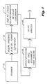
- Fig. 1 is a functional block diagram of the image conversion system according to the present invention.
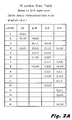
- Fig. 2A is a table of 16 levels of gray scale and is based upon the use of a two-by-two super pixel.
- Fig. 2B is a table of 32 levels of gray scale and is also based upon the use of a two-by-two super pixel.
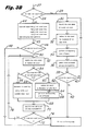
- Figs. 3A and 3B are respectively the upper and lower portions of a schematic flow chart depicting the data processing methodology and structure used for controlling the operation of the error diffusion and pixel assignment gray scaling stage in Fig. 1.
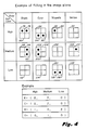
- Fig. 4 is a matrix showing three rows and four columns of 2x2 super pixels to illustrate the assignment of ink drops to each pixel based upon the value of the digits in each assigned gray scale digital number.
- Referring now to Fig. 1, a
scanner 10 may be used to convert a color image into digital gray scale data for application to an additive red-green-blue (R-G-B)format conversion stage 12. The R-G-B output data from theformat conversion stage 12 is applied as indicated to the subtractive color primaries cyan-yellow-magenta (C-Y-M) color conversion stage in a well known manner and including 100% undercolor removal to obtain black. A chromatic color (black) cannot be easily made by mixing Y-M-C ink colors, and such mixing will increase the amount of ink consumed. Therefore, the black created by YMC colors is more preferable replaced by pure black (K). This replacement and the generation of pure black is known in the art as undercolor correction or undercolor removal (UCR). - The use of 100% undercolor removal is for the purpose of minimizing ink consumption and to improve resolution. The equation for 100% UCR for colors C, M, Y and K is K = min (C, M, Y) where the new C = C-K, the new M = M-K and the new Y = Y-K.
- The output of the C-Y-M
color conversion stage 14 is a digital data stream which is applied to the error diffusion andpixel assignment stage 16, and the latter stage in turn drives acolor printer 18, preferably a thermal ink jet color printer. The general functional arrangement of the image scanning and reproduction system of Fig. 1 is generally well known in the image processing art. The image processing operation and capability of such a system is described, for example, in the March 1987 issue of BYTE Magazine in an article by B. M. Dawson entitled "Introduction To Image Processing Algorithms" at page 169 et seq. Such image processing capability and corresponding system operation is also described in a publication by Gary Dispoto et al entitled Designer's Guide to Raster Image Printer Algorithms, First Edition, December 1986, Copyrighted by and available from the Hewlett-Packard Company in Palo Alto, California. Both of these latter references are incorporated herein by reference. - The processes of error diffusion and pixel assignment in a gray scaling image processing operation are also generally well known in this art. Error diffusion is a technique used to disperse to the neighboring pixels the error between a printable gray scale and the input image data gray scale. This error diffusion has been frequently carried out using a selected one of many well known algorithms such as those discussed in the above identified Dawson article. As an example, this error diffusion may be carried our using either one of two well known algorithms in this art, namely, Floyd and Steinberg's 4-point algorithms and Stucke's 12-point algorithms.
- In 1976, Robert W. Floyd and Lewis Steinberg published a paper in the Proceedings of the Society of Information Display, Vol. 17/2 entitled "An Adaptive Algorithm For Spacial Gray Scale", and in this article there is described an algorithm which is entitled "Error Diffusion". As indicated above and described in detail in the Floyd and Steinberg paper, error diffusion is a technique used to disperse the difference between the actual gray scale of the read pixel values and the subsequently assigned row and column (i,j) gray scale of a look-up gray table into the pixels which surround the assigned gray scale pixels. This error diffusion is done in such a manner as to minimize smearing of the image reproduced. The above Floyd and Steinberg paper is incorporated herein by reference.
- Other error diffusion techniques are identified in U.S. Patent No. 4,680,645 issued to Dispoto et al, assigned to the present assignee and also incorporated herein by reference.
- Referring now to Fig. 2A, there is shown a 16 level gray table based upon a two-by-two super pixel and also based upon a high-medium-low dye loading for each 3 digit gray scale number and weighted as indicated to be in the reflectance density ratio of 4:2:1. Thus, the left hand digit of each gray scale number in each row and column of the 16 level gray table in Fig. 2A represents a high (H) dye loading, the middle digit of each 3-digit gray scale number represents the medium (M) dye loading and the right hand digit of each number represents a low (L) dye loading for each drop of ink ejected onto a pixel. Each of these H, M and L dye loadings is selected to give a 4:2:1 reflectance ratio on the printed page as will be understood by those skilled in the art.
- The
numbers scanner 10 in Fig. 1. This assigned gray scale value is the closest gray scale number in the gray table in Fig. 2A to the actually read pixel values. - The blank areas of the table shown in Fig. 2A to which no drop count numbers are assigned are all (0, 0, 0). Therefore, the 3 digit drop count gray scale numbers shown in Fig. 2A are the only numbers in the 16-level gray table having one or more positive digits of either a 1, 2, 3 or 4 value corresponding to available drop counts within the 16 gray scale levels.
- There are actually 256 levels in a complete gray scale used in practicing this invention. This number 256 is a convenient even number in the digital signal processing art and has far more resolution in gray scale than is normally needed. The human eye can resolve only about 50 gray levels between maximum white and maximum black. Also, the number 256 is a typical level resolution number for the
scanner 10. Therefore, each of the 16 levels in Fig. 2A represent one sixteenth of the total 256 level gray scale. Thus, in level one (1) of the table in Fig. 2A, the (0, 0, 1) notation indicates that the only available drop count and dye loading for achieving a level one of the gray table is a single drop or drop count having a low (L) or one weighted dye loading. Similarly, a level two of gray scale may be achieved by using either one drop of a medium (M) dye loading (0, 1, 0) or two drops of a low dye loading (0, 0, 2), as indicated in level two of the table, and so on down the table. However, it will be understood by those skilled in the art that many other gray levels may be used instead of the 16 levels indicated in Fig. 2A. - For example, a 32 level gray table is especially well suited for use in practicing the present invention and would be used in combination with a 8:3:1 reflectance ratio in an arrangement shown in Fig. 2B. It will be observed in Fig. 2B that
level 15 of the table has no exact available gray scale number for achieving theexact level Level 15 can be achieved by using alevel 14 in combination with an error diffusion. The selection of the above gray scale numbers in Figs. 2A and 2B which define and control the available drop counts and dye loadings will become better understood in the following descriptions of Figs. 3-4. - Referring now to Figs. 3A and 3B, the data processing system shown in these two connected figures provides a detailed explanation of the operation of the error diffusion and
pixel assignment stage 16 in Fig. 1. This data processing system is comprised of a number of functional blocks which include therein descriptive legend to aid in the reader's understanding of the invention. These functional blocks are actually individual stages of a computer, and as such are sometimes alternatively referred to as "stages" or "test stages" in the case of performing a yes-no test on a particular piece of data. The test stages in this system are indicated by the diamond shaped functional blocks, whereas the other operational stages which perform a specific functional operation on the incoming data are rectangular in shape. However, for the ease of describing this data processing system and its two feedback loops, each of the functional blocks or stages therein will be referred to hereinafter as "steps" in order to generically indicate the functional steps performed on the data being operated on in each of the electronic stages. - As indicated at
step 20, each of the black, cyan, magenta and yellow pixel values are read by thescanner 10 in Fig. 1 and converted to C, Y, M and K digital data, each having a row and column, (i, j,) within the 256 level gray scale. As indicated atstep 22, each of the black, cyan, magenta and yellow gray levels fromstep 20 are assigned their closest corresponding gray scale number within the gray table of Fig. 2A, and the difference between the actual and assigned gray levels are diffused by error diffusion atstep 24 into the surrounding pixels as previously described. - At
step 26, a total drop count is calculated for the black, cyan, magenta and yellow minimum available drop count numbers within the 16 level gray table of Fig. 2A, and this drop count minimum is compared atstep 28 in Fig. 3B to a predetermined maximum allowable drop count, Vmax, as previously defined. If the total drop count minimum atstep 28 is greater than Vmax, then the color plane of the highest drop count, Dmax1, of the group of drop counts for the colors C, Y, M and K is identified atstep 30, reduced (decremented) in drop count atstep 32 to its next lower value in the gray scale and the difference between the newly assigned gray scale number and the actually read gray scale number is used to produce a corresponding error diffusion atstep 34. Thereafter, the new total drop count is updated atstep 36 and then again compared to Vmax atstep 38. If the total drop count atstep 38 is now less than Vmax, then the correct corresponding digital data is generated online 40 and is used to drive a colorink jet printer 18 in Fig. 1. If the total drop count atstep 38 is still greater than Vmax, then a feedback signal generated in thefeedback loop 42 is utilized to then again identify the color plane of the next existing highest C, Y, M, or K drop count atstep 30 and the process in theloop - If the total drop count at
step 28 is now less than Vmax, then thestep 44 is operative to generate a total drop count sum of all the maximum drop count numbers in the gray table of Fig. 2A for each of the K, C, M and Y assigned pixel values. This sum of the total K, C, M and Y drop count maximums is then compared at step 46 to Vmax. If this total drop count sum is less than Vmax, a signal online 48 is generated and is used to drive a color printer and no further signal processing is necessary. If, however, the total maximum drop count sum at step 46 is now greater than Vmax, then the output signal online 50 from step 46 is applied to step 52 and therein used to identify the color plane of the next highest individual drop count, Dmax2, of each of the previously summed K, C, M and Y drop count maximums. - If there is then existing a lower drop count gray scale number at the same gray level within the table of Fig. 2A as determined in
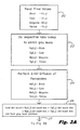
step 54, then a signal online 56 fromstep 54 is generated and is used to decrement the drop count instep 58 by going to the next lower drop count maximum number within the same level of the gray table in Fig. 2A. If, however, no lower drop count number exists for the same level of gray scale as determined instep 54, then a signal generated online 60 fromstep 58 is applied to thestep 62 where it is used to reduce the drop count number by decrementing the level of the gray table instep 62 to its next lowest gray level wherein a new drop count maximum number is selected. Then, an output signal online 64 is applied to thestep 66 where an error diffusion is performed to generate an error diffusion signal online 68. The signal online 68 is applied to thenext step 70 where the total drop count maximum is updated atstep 70 and then fed to anoutput comparator 76. Here in thecomparator 70 the updated total drop count number is again compared to Vmax to insure that the newly updated drop count number does not now still exceed Vmax. If Vmax is not exceeded, a signal online 74 is generated to drive the color printer. However, if the total drop count instep 70 still exceeds Vmax, then a feedback signal online 76 is returned vialine 50 to the input ofstep 52 to again identify the color plane of the then existing next highest drop count for each of the group of K, C, M and Y maximum drop count gray scale numbers. - The following code in TABLE I is referred to in the image processing art as a "pseudo code" and is a statement of all of the various steps described above with reference to Figures 3A and 3B:


- An example of the above minimum and maximum C, Y, M and K drop counting and initial gray scale assignment is as follows: Assume that the read pixel values on the 256 level gray scale are K = 20, C = 50, M = 35 and Y = O. Converting these values to the 16 level gray scale will yield K =1 plus a remainder of 4, C = 3 plus a remainder of 2, M = 2 plus a remainder of 3, and Y = O. The above remainders are diffused via error diffusion into the surrounding pixels and using the well known Floyd and Steinberg algorithm. This error diffusion is made into pixels surrounding the particular chosen pixel within the above gray levels of 1, 3 and 2. From the table in Fig. 2A, the drop count minimum for the above 1, 3, 2 and O levels of gray scale are Kgmin = 1, Cymin = 2, Mgmin = 1 and Ygmin = O or a total minimum drop count of 4. The drop count maximum for these same levels of gray scale are Kgmax = 1, Cgmax = 3, Mgmax = 2 and Ygmax = O, or a total maximum drop count of 6. Thus, if the maximum allowable drop count for each 2
X 2 super pixel is 8 drops, then the minimum (4) and maximum (6) drop count numbers given above will both be less than Vmax and a measurement of the total maximum drop count in step 46 of Fig. 3B will in turn generate an output signal online 48 for directly controlling thecolor printer 18. - In another example of C, Y, M and K drop counting, assume that K=70, C=75, M=35 and Y=0. Converting these values to the 16 level gray scale will yield Kg=4 with a remainder Ke=6; Cg=4 with a remainder Ke=11; Mg=2 with a remainder Me=3; and Yg=0 with a remainder Ye=0. From the table in Fig. 2A, the drop count minimum for the above Kgmin, Cgmin, Mgmin and Ygmin values is 1+1+1+0=3, whereas the drop count maximum for the above Kgmax, Cgmax, Mgmax and Ygmax values is 4+4+2+0=10. Thus, if Vmax = 8, the drop count minimum output signal from
step 26 is not greater than Vmax, so that no drop count minimum output signal is applied fromstep 28 to step 30, and step 44 is now activated. However, since the drop count maximum of 10 exceeds a Vmax of 8, the now activatedstep 44 begins a maximum drop counting function as previously described above with reference to Fig. 3B. This operation in turn will activate the test step 46 and ask step 46 if a drop count of 10 is greater than a Vmax of 8. Since this answer is "yes", then step 52 is activated to identify the color plane of the highest drop count in this gray scale reading which is K = 4, or the input data which is applied to step 54. Since a lower drop count does exist at the same gray scale level as the level for K = 4, and this lower drop count is K = 3 as indicated in thelevel line 56 and is applied to step 58 which decrements the drop count to K = 3.Step 58 reduces or decrements the new total drop count sum to 9 instead of 10. The updating of the new drop count sum is performed instep 70. - Now, is the new drop count sum of 9 still greater than a Vmax of 8? The answer is "yes" as is indicated in
step 72, and thus a feedback signal online 76 is applied to step 52 to again identify the color plane of the next highest drop count. As indicated in the numbers of this example, the answer is C = 4 and this information is applied to step 54 where C = 4 is used to determine if a lower drop count for C or cyan exists at the same gray level in Fig. 2A as the level for C = 4. Since the answer is "yes", the signal generated online 56 is applied again to step 58 where C = 4 is decremented to C = 3 and then applied to step 70. In step 70 a new total drop count sum of 8 is generated and is applied to step 72 for receiving another new drop count comparison. - Since the new drop count total of 8 is not greater than a Vmax of 8, a "no" signal is generated on
line 74 and is applied to either acolor printer 18 in real time or stored in a printer storage file for subsequent use. - In yet a third example of C, Y, M and K drop counting, assume that the read pixel values are as follows: K = 85, C = 85, M = 85, Y = 0. Converting these values to the 16 level gray scale will yield Kg = 5 + Ke = 5; Cg = 5 + Ce = 5; Mg = 5 + Me = 5; and Yg = 0 and Ye = 0. From the table in Fig. 2A, the drop count minimum for Kgmin, Cgmin, Mgmin and Ygmin, respectively = 2+2+2+0=6, and the drop count maximum for Kgmax, Cgmax, Mgmax and Ygmax, respectively = 3+3+3+0=9. Assume further for this particular example that Vmax = 5, so that the drop count minimum sum is greater than Vmax and a "yes" output signal is generated on
line 29 and applied to step 30 to thereby activate thesubsequent steps feedback loop 42 as previously described. Here in thisloop containing steps feedback line 42 the drop count minimum selection from the gray table of Fig. 2A will be decremented as previously described until a "no" output signal is generated on theoutput line 40 from the yes/notest step 38. - When using a multidrop color imaging system such as the one described in the above U.S. Patent No. 4,680,645 issued to Dispoto et al which fires drops on top of drops in a single pixel, the drop count and dye loading selection process is complete at this point. However, when the drops are fired into super pixels such as a 2X2 super pixel, the fired drops must now be assigned to a desired pixel quadrant as they are sequentially fired in to the super pixel. This operation is described below with reference to Fig. 4.
- Fig. 4 shows a matrix of 12 color planes of 2X2 super pixels including three rows of high, medium, and low dye loadings versus four columns of black, cyan, magenta and yellow colors. Although these twelve super pixels are shown as being physically separated in Fig. 4, it will be understood by those skilled in the art that these super pixels are all superimposed on one another in the print scanning operation described below and thereby actually occupy the same space on the print media. Accordingly, the physical separation of these twelve super pixels in Fig. 4 is made for purposes of explanation only.
- These super pixels are sequentially addressed from left to right and starting at the top or H row and then proceeding vertically down through the M & L rows in the normal manner of scanning a printed surface area. These 12 super pixels represent the timed sequence of successive dot printing in order to achieve a minimum of color contrast on a printed page. The black, cyan, magenta and yellow colors are arbitrarily assigned designated digits of 0, 1, 2 and 3, respectively, whereas the high, medium and low levels of dye loading are assigned weighted units of 0, 1 and 2 respectively. Thus, when one is printing sequentially from left to right and then scanning vertically down the matrix in Fig. 4, the individually assigned pixels for receiving successive drops of ink are continuously changed in a clockwise rotation in moving from pixel to pixel. In this manner, each successively printed pixel receives in succession (and in accordance with its assigned gray scale drop count number) the colors C, Y, M and black cycled in order through the high, medium and low dye loadings.
- The firing sequence of the color printhead of the ink jet printer under control is continuously controlled to print the next adjacent quadrant of each super pixel as each super pixel is printed in succession. This clockwise (or counter clockwise) clocking action continues to rotate the location of each next printed individual pixel to the next super pixel quadrant, so that each successively printed drop of ink is rotated to the next adjacent quadrant of each super pixel until all of the scanned super 2x2 pixels are printed in succession. In this manner, the ink is distributed over the entire super pixel matrix in Fig. 4 in a highly uniform manner, and this operation minimizes the ink volume per unit of printed area ratio for an ink jet printing operation. This action in turn simultaneously minimizes both paper cockleing and color contrast or grainyness of the printed hardcopy output from an ink jet printer.
- The above operation will be better understood with reference to an example of the finally adjusted gray scale information which is applied to the color printer or
printer storage file 18 from one of the input lines 40, 48 or 74 connected thereto as shown in Fig. 3B. As shown in the example of Fig. 4, assume that the "High" column of K, C, M and Y data is 2, 2, 1, 0, that the "Medium" column of K, C, M, and Y data is 2, 2, 0, 1 and that the "Low" column of K, C, M, Y data is 0, 0, 2, 0. Using this gray scale K, C, M and Y information, the pixel rotational and scanning operation will proceed as follows: The K = 2 in the "High" dye loading column will eject drops intoquadrants 76 and 78 of thesuper pixel 80. Then, rotating clockwise, the C = 2 "High" dye loading will eject drops in the next clockwiseadjacent quadrants 82 and 84 of the nextsuper pixel 86. For M = 1 in the "High" column, a drop is ejected inadjacent quadrant 88 of the next adjacentsuper pixel 90. Then, for Y = 0 the nextsuper pixel 92 is skipped. - Next the "Medium" dye loading column is addressed and K = 2 therein puts drops in
quadrants 94 and 96 in super pixel 98; C = 2 puts drops in the next adjacentclockwise quadrants super pixel 104; M = 0 causes the nextsuper pixel 106 to be skipped; and Y = 1 then puts a drop in quadrant of super pixel 110. - Continuing, a "Low" column K = 0 and C = 0 causes
super pixels 112 and 114 to be skipped, respectively; a low M = 2 puts drops in the next adjacentclockwise quadrants super pixel 120 and a low Y = 0 causes thelast pixel 122 of the matrix to be skipped. Then the above described operation is repeated for the next received gray scale data applied to theprinter 18. - The above pixel selection process described with reference to Fig. 4 is defined in code form by the following pseudo code shown in the table below for the 2X2 super pixel assignment - defining data structure.

- The scheme of dots assignment to a 2X2 super-pixel is to assign the dots counts in the sequence of their highest gray level plane from black, cyan, magenta to yellow. This scheme is then repeated as described in the example given above for medium and low gray level.
- Various modifications may be made in the above described embodiment without departing from the scope of this invention. As an example, a different dye loading ratio of 8:3:1 may be used with a 32 level gray scale and with a 2x2 super pixel in accordance with the above teachings. In addition, this invention may be used with different size drop volumes or with multi-drop formatting where the print area is only a single pixel. However, in the multi-drop printing process, higher print frequencies are required as compared to those required by the present invention. Also, the present invention is not limited to use by thermal ink jet printers, and may be used with other different types of ink jet printers such as thermal transfer or piezoelectric ink jet printers.
- The present invention may also be modified by one skilled in the art to make it adaptable for use with different ink drop volumes (e.g. 160, 80 and 40 picoliters) such as those described in commonly assigned U.S. Patent No. 4,746,935 issued to Ross R. Allen. Using a suitable modification of the data processing methodology shown in Figs. 3A and 3B, it is possible to accommodate the used of multiple drop sizes with or without the use of multiple gray levels.
- In priority of selecting the highest drop count from the (C, Y, M, K) colors, there may be an advantage to modify this set to only (C, M, Y) colors only and to leave the black or K plane of information intact. This is because the black plane contains most of the resolution information, and this is especially true for the case of 100% UCR Where the error diffusion of the color plane will only slightly alter the chromaticity of the printed image. Additionally, the visual perception is more sensitive to resolution than it is to color information.
- Finally, as a practical matter, the yellow gray scale is of least importance, so from both a hardware and a software standpoint, a single dye level of yellow would be acceptable.
Claims (12)
Applications Claiming Priority (2)
| Application Number | Priority Date | Filing Date | Title |
|---|---|---|---|
| US278881 | 1988-12-02 | ||
| US07/278,881 US4930018A (en) | 1988-12-02 | 1988-12-02 | Method and system for enhancing the quality of both color and black and white images produced by ink jet printers |
Publications (3)
| Publication Number | Publication Date |
|---|---|
| EP0372826A2 true EP0372826A2 (en) | 1990-06-13 |
| EP0372826A3 EP0372826A3 (en) | 1992-04-15 |
| EP0372826B1 EP0372826B1 (en) | 1996-03-06 |
Family
ID=23066773
Family Applications (1)
| Application Number | Title | Priority Date | Filing Date |
|---|---|---|---|
| EP89312460A Expired - Lifetime EP0372826B1 (en) | 1988-12-02 | 1989-11-30 | Method and system for enhancing the quality of both color and black and white images produced by ink jet printers |
Country Status (6)
| Country | Link |
|---|---|
| US (1) | US4930018A (en) |
| EP (1) | EP0372826B1 (en) |
| JP (1) | JP2980331B2 (en) |
| CA (1) | CA1322891C (en) |
| DE (1) | DE68925871T2 (en) |
| HK (1) | HK161296A (en) |
Cited By (22)
| Publication number | Priority date | Publication date | Assignee | Title |
|---|---|---|---|---|
| EP0454448A2 (en) * | 1990-04-27 | 1991-10-30 | Hewlett-Packard Company | Method and system for enhancing the quality of both color and black and white images produced by ink jet and electrophotographic printers |
| EP0562755A2 (en) * | 1992-03-25 | 1993-09-29 | Scitex Corporation Ltd. | A technique for generating image reproduction |
| EP0722835A1 (en) * | 1994-05-11 | 1996-07-24 | Seiko Epson Corporation | Ink jet recording method and recording apparatus |
| WO1996032812A1 (en) * | 1995-04-12 | 1996-10-17 | Eastman Kodak Company | Improvements in image halftoning |
| WO1996032809A1 (en) * | 1995-04-12 | 1996-10-17 | Eastman Kodak Company | A color photocopier using a drop on demand ink jet printing system |
| EP0791892A2 (en) * | 1995-09-08 | 1997-08-27 | Canon Kabushiki Kaisha | Image processing apparatus and method |
| EP0820187A2 (en) * | 1996-07-18 | 1998-01-21 | Seiko Epson Corporation | Printing system and method of recording images |
| EP0790130A3 (en) * | 1996-02-13 | 1998-06-17 | Sony Corporation | Printing apparatus and method for suppressing emission of excess dilution liquid |
| EP0850767A1 (en) * | 1996-12-04 | 1998-07-01 | Canon Kabushiki Kaisha | Recording apparatus and method of controlling same |
| US5805178A (en) * | 1995-04-12 | 1998-09-08 | Eastman Kodak Company | Ink jet halftoning with different ink concentrations |
| EP0863019A1 (en) * | 1996-07-18 | 1998-09-09 | Seiko Epson Corporation | Printer and image recording method |
| EP0889640A2 (en) * | 1997-06-30 | 1999-01-07 | Xerox Corporation | Sum and difference error diffusion |
| EP0803370A3 (en) * | 1996-04-23 | 1999-06-09 | Canon Kabushiki Kaisha | Ink-jet print method and apparatus |
| EP0925928A3 (en) * | 1997-12-26 | 2000-01-26 | Canon Kabushiki Kaisha | A recording apparatus and a recording method |
| US6120121A (en) * | 1991-06-07 | 2000-09-19 | Canon Kabushiki Kaisha | Recording apparatus and a method of forming driving data |
| US6142600A (en) * | 1996-04-23 | 2000-11-07 | Canon Kabushiki Kaisha | Print control method and printer |
| US6145950A (en) * | 1996-04-23 | 2000-11-14 | Canon Kabushiki Kaisha | User interface, printing system using user interface and print control method |
| EP1057648A1 (en) * | 1998-02-09 | 2000-12-06 | Copyer Co., Ltd. | Ink-jet recording method and device |
| US6158836A (en) * | 1996-04-23 | 2000-12-12 | Canon Kabushiki Kaisha | Print method and apparatus |
| US6260938B1 (en) | 1996-04-23 | 2001-07-17 | Canon Kabushiki Kaisha | Ink-jet printing method and apparatus for printing with inks of different densities |
| WO2009031165A1 (en) | 2007-09-03 | 2009-03-12 | Telecom Italia S.P.A. | Image processing method and apparatus |
| EP1939004A3 (en) * | 1998-05-29 | 2009-12-23 | Canon Kabushiki Kaisha | Complementary recordin system using multi-scan |
Families Citing this family (52)
| Publication number | Priority date | Publication date | Assignee | Title |
|---|---|---|---|---|
| US5537230A (en) * | 1988-02-24 | 1996-07-16 | Mitsubishi Denki Kabushiki Kaisha | Signal processing device for video printer |
| US5016191A (en) * | 1988-09-02 | 1991-05-14 | Tektronix, Inc. | Half toning pixel processor |
| JP2791066B2 (en) * | 1988-11-15 | 1998-08-27 | キヤノン株式会社 | Recording device |
| DE69023044T2 (en) * | 1989-06-02 | 1996-04-11 | Canon Kk | A recording apparatus and method for use therein to produce multiple dots in a picture element. |
| ES2091288T3 (en) * | 1990-04-20 | 1996-11-01 | Canon Kk | PRINTING DEVICE. |
| US5260807A (en) * | 1992-06-05 | 1993-11-09 | Eastman Kodak Company | Method and apparatus for imbedding controlled structure for gray scale rendering |
| US5515479A (en) * | 1992-07-23 | 1996-05-07 | Xerox Corporation | Image processing method to reduce marking material coverage in printing processes |
| US5633662A (en) * | 1992-08-05 | 1997-05-27 | Hewlett-Packard Company | Ink limiting in ink jet printing systems |
| US5539667A (en) * | 1992-09-15 | 1996-07-23 | Gcc Technologies | Method and apparatus for improved digital film recorder |
| US5508826A (en) * | 1993-04-27 | 1996-04-16 | Lloyd; William J. | Method and apparatus for calibrated digital printing using a four by four transformation matrix |
| US5434672A (en) * | 1993-06-23 | 1995-07-18 | Hewlett-Packard Company | Pixel error diffusion method |
| US5485183A (en) * | 1993-06-30 | 1996-01-16 | Dataproducts Corporation | Interlaced dot-on-dot printing |
| US5621546A (en) * | 1993-11-02 | 1997-04-15 | Xerox Corporation | Method and apparatus for vector error diffusion with output color control |
| US5519815A (en) * | 1993-11-29 | 1996-05-21 | Xerox Corporation | Image processing method to reduce marking material coverage in printing processes |
| US5563985A (en) * | 1994-01-05 | 1996-10-08 | Xerox Corporation | Image processing method to reduce marking material coverage in printing processes |
| US6106093A (en) * | 1994-06-17 | 2000-08-22 | Canon Kabushiki Kaisha | Ink jet recording apparatus capable of recording in different resolutions, and ink jet recording method using such apparatus |
| GB2291838B (en) * | 1994-07-29 | 1998-11-18 | Robert John Young | A machine and method for printing on an edible substrate |
| US6536345B1 (en) | 1994-07-29 | 2003-03-25 | Cadex Limited | Printing on the surface of edible substrates |
| US5635967A (en) * | 1994-08-15 | 1997-06-03 | Xerox Corporation | Image processing method to reduce marking material coverage in printing processes |
| US5649071A (en) * | 1994-09-26 | 1997-07-15 | Xerox Corporation | Image processing method to reduce marking material coverage in sequential color printing processes |
| US6072902A (en) * | 1995-05-03 | 2000-06-06 | Apple Computer, Inc. | Method and system for color matching between digital display devices |
| US5982990A (en) * | 1995-07-20 | 1999-11-09 | Hewlett-Packard Company | Method and apparatus for converting color space |
| US5880752A (en) * | 1996-05-09 | 1999-03-09 | Hewlett-Packard Company | Print system for ink-jet pens |
| US5894358A (en) * | 1996-06-27 | 1999-04-13 | Xerox Corporation | Adaptable color density management system |
| US6081340A (en) * | 1997-03-31 | 2000-06-27 | Xerox Corporation | Image processing method to reduce marking material coverage with non-linear specifications |
| US6135655A (en) * | 1997-10-14 | 2000-10-24 | Hewlett-Packard Company | Multipixel dots in monochrome drop-on-demand printing |
| US6539110B2 (en) * | 1997-10-14 | 2003-03-25 | Apple Computer, Inc. | Method and system for color matching between digital display devices |
| US6068361A (en) * | 1997-10-30 | 2000-05-30 | Mantell; David A. | Method and apparatus for multiple drop error diffusion in a liquid ink printer |
| US6014227A (en) * | 1998-04-30 | 2000-01-11 | Hewlett-Packard Co. | Printer with progressive column error diffusion system and method of using same for improved printer throughput |
| US6179407B1 (en) | 1998-11-20 | 2001-01-30 | Hewlett-Packard Company | Multi-pass inkjet printer system and method of using same |
| US6407825B1 (en) | 1998-12-17 | 2002-06-18 | Eastman Kodak Company | Colorant reduction method for digital images |
| US6445463B1 (en) * | 1999-01-19 | 2002-09-03 | Xerox Corporation | Image processing method to reduce marking material coverage in printing processes |
| US6172692B1 (en) | 1999-02-11 | 2001-01-09 | Lexmark International, Inc. | Multilevel ink mixing device and method using diluted and saturated color inks for inkjet printers |
| US6161919A (en) * | 1999-02-22 | 2000-12-19 | Xerox Corporation | Ink coverage reduction method for printers capable of printing multiple drop sizes |
| US6765693B1 (en) | 2000-03-20 | 2004-07-20 | Sharp Laboratories Of America, Inc. | Photo quality color printing by using light black ink |
| US7050195B1 (en) | 2000-04-20 | 2006-05-23 | Hewlett-Packard Development Company, L.P. | Printed medium data storage |
| US20020154327A1 (en) * | 2001-04-24 | 2002-10-24 | Jones Michael J. | Incorporating data in hardcopy correspondence |
| US7190485B2 (en) * | 2001-06-14 | 2007-03-13 | Eastman Kodak Company | Method for multilevel printing of digital images using reduced colorant amounts |
| US6435657B1 (en) | 2001-08-20 | 2002-08-20 | Eastman Kodak Company | Method for multicolorant printing of digital images using reduced colorant amounts |
| US7061645B2 (en) * | 2001-09-27 | 2006-06-13 | Sharp Laboratories Of America, Inc. | Non-segmentation, individual pixel-by-pixel-based image rendering system |
| US7044573B2 (en) * | 2002-02-20 | 2006-05-16 | Lexmark International, Inc. | Printhead alignment test pattern and method for determining printhead misalignment |
| US20030179410A1 (en) * | 2002-03-21 | 2003-09-25 | Velde Koen Van De | Multilevel colour error-diffusion providing reduced sensitivity to printing process variability errors |
| US7245395B2 (en) * | 2002-12-04 | 2007-07-17 | Eastman Kodak Company | Calibrating a digital printer using a cost function |
| US7239422B2 (en) * | 2002-12-04 | 2007-07-03 | Eastman Kodak Company | Color gamut mapping using a cost function |
| US7173734B2 (en) * | 2002-12-11 | 2007-02-06 | Xerox Corporation | Intercolor bleed reduction in liquid ink printers |
| US7196817B2 (en) * | 2002-12-12 | 2007-03-27 | Eastman Kodak Company | Printing of digital images using reduced colorant amounts while preserving perceived color |
| JP4235569B2 (en) * | 2003-02-26 | 2009-03-11 | キヤノン株式会社 | Recording method and recording apparatus |
| US7152964B2 (en) * | 2003-05-21 | 2006-12-26 | Eastman Kodak Company | Very high speed printing using selective deflection droplet separation |
| US20050003056A1 (en) * | 2003-07-02 | 2005-01-06 | The Procter & Gamble Company | Article of commerce comprising edible substrate, image, and message |
| US7593563B2 (en) * | 2003-07-11 | 2009-09-22 | The Procter & Gamble Company | Image variety on edible substrates |
| US20050058753A1 (en) * | 2003-09-17 | 2005-03-17 | The Procter & Gamble Company | Method to increase image variety with limited image components |
| US20050058749A1 (en) * | 2003-09-17 | 2005-03-17 | The Procter & Gamble Company | Image exposure control in edible substrates |
Citations (6)
| Publication number | Priority date | Publication date | Assignee | Title |
|---|---|---|---|---|
| DE3037774A1 (en) * | 1980-10-06 | 1982-04-15 | Siemens AG, 1000 Berlin und 8000 München | Method and arrangement for displaying multicolor halftone images |
| GB2094095A (en) * | 1981-02-06 | 1982-09-08 | Fuji Photo Film Co Ltd | Coloured ink recording method |
| DE3415778A1 (en) * | 1983-04-28 | 1984-10-31 | Canon K.K., Tokio/Tokyo | METHOD FOR PRODUCING A HALFTONE IMAGE |
| US4595948A (en) * | 1982-10-13 | 1986-06-17 | Ricoh Company, Ltd. | Multicolor ink jet recording apparatus having means for preventing blurring of ink |
| US4680645A (en) * | 1986-08-25 | 1987-07-14 | Hewlett-Packard Company | Method for rendering gray scale images with variable dot sizes |
| US4686538A (en) * | 1984-10-31 | 1987-08-11 | Canon Kabushiki Kaisha | Tone recording method |
Family Cites Families (11)
| Publication number | Priority date | Publication date | Assignee | Title |
|---|---|---|---|---|
| JPS5952069B2 (en) * | 1977-12-15 | 1984-12-18 | 凸版印刷株式会社 | Ink usage prediction device |
| JPH0639185B2 (en) * | 1983-07-15 | 1994-05-25 | キヤノン株式会社 | Color image reproduction method |
| JPS6015165A (en) * | 1983-07-08 | 1985-01-25 | Canon Inc | Color image reproduction method |
| US4635078A (en) * | 1983-04-28 | 1987-01-06 | Canon Kabushiki Kaisha | Intermediate gradient image producing method |
| US4503444A (en) * | 1983-04-29 | 1985-03-05 | Hewlett-Packard Company | Method and apparatus for generating a gray scale with a high speed thermal ink jet printer |
| JPS60152172A (en) * | 1984-01-19 | 1985-08-10 | Canon Inc | Device for forming color picture |
| JPS6125365A (en) * | 1984-07-13 | 1986-02-04 | Canon Inc | Method for forming half-tone picture |
| US4680596A (en) * | 1984-08-02 | 1987-07-14 | Metromedia Company | Method and apparatus for controlling ink-jet color printing heads |
| US4638373A (en) * | 1985-03-06 | 1987-01-20 | Metromedia, Inc. | Method and apparatus for improving gray scale resolution in an ink jet printing system |
| US4746935A (en) * | 1985-11-22 | 1988-05-24 | Hewlett-Packard Company | Multitone ink jet printer and method of operation |
| JPS63147654A (en) * | 1986-12-12 | 1988-06-20 | Canon Inc | Ink jet printer |
-
1988
- 1988-12-02 US US07/278,881 patent/US4930018A/en not_active Expired - Lifetime
-
1989
- 1989-09-27 CA CA000613607A patent/CA1322891C/en not_active Expired - Fee Related
- 1989-11-30 DE DE68925871T patent/DE68925871T2/en not_active Expired - Fee Related
- 1989-11-30 EP EP89312460A patent/EP0372826B1/en not_active Expired - Lifetime
- 1989-12-01 JP JP1313118A patent/JP2980331B2/en not_active Expired - Fee Related
-
1996
- 1996-08-29 HK HK161296A patent/HK161296A/en not_active IP Right Cessation
Patent Citations (6)
| Publication number | Priority date | Publication date | Assignee | Title |
|---|---|---|---|---|
| DE3037774A1 (en) * | 1980-10-06 | 1982-04-15 | Siemens AG, 1000 Berlin und 8000 München | Method and arrangement for displaying multicolor halftone images |
| GB2094095A (en) * | 1981-02-06 | 1982-09-08 | Fuji Photo Film Co Ltd | Coloured ink recording method |
| US4595948A (en) * | 1982-10-13 | 1986-06-17 | Ricoh Company, Ltd. | Multicolor ink jet recording apparatus having means for preventing blurring of ink |
| DE3415778A1 (en) * | 1983-04-28 | 1984-10-31 | Canon K.K., Tokio/Tokyo | METHOD FOR PRODUCING A HALFTONE IMAGE |
| US4686538A (en) * | 1984-10-31 | 1987-08-11 | Canon Kabushiki Kaisha | Tone recording method |
| US4680645A (en) * | 1986-08-25 | 1987-07-14 | Hewlett-Packard Company | Method for rendering gray scale images with variable dot sizes |
Non-Patent Citations (2)
| Title |
|---|
| ICASSP 86 Proceedings, 7-11 April 1986, Tokyo (JP) (International Conference on Acoustics, Speech, and Signal Processing), vol. 1, 1986, New York (US) pages 541-544; K. Yamada et al.: "A Representation Method of Color Pictures by Arranging Fixed Size Dots of the Primary Colors" * |
| Proceedings of the Third International Congress on Advances in Non-impact Printing Technologies, 24-28 August 1986, San Francisco, California US, The Society for Imaging and Technology, Springfield, VA (US) pages 252-264 S. SUGIURA et al.: "Multibus-based color correcting hardware providing faster processing for bubble jet color printer" * |
Cited By (41)
| Publication number | Priority date | Publication date | Assignee | Title |
|---|---|---|---|---|
| EP0454448A3 (en) * | 1990-04-27 | 1993-02-24 | Hewlett-Packard Company | Method and system for enhancing the quality of both color and black and white images produced by ink jet and electrophotographic printers |
| EP0454448A2 (en) * | 1990-04-27 | 1991-10-30 | Hewlett-Packard Company | Method and system for enhancing the quality of both color and black and white images produced by ink jet and electrophotographic printers |
| US6120121A (en) * | 1991-06-07 | 2000-09-19 | Canon Kabushiki Kaisha | Recording apparatus and a method of forming driving data |
| EP0562755A2 (en) * | 1992-03-25 | 1993-09-29 | Scitex Corporation Ltd. | A technique for generating image reproduction |
| EP0562755A3 (en) * | 1992-03-25 | 1994-01-26 | Scitex Corp Ltd | |
| US5473733A (en) * | 1992-03-25 | 1995-12-05 | Scitex Corporation Ltd. | Technique for generating image reproduction |
| EP0722835A1 (en) * | 1994-05-11 | 1996-07-24 | Seiko Epson Corporation | Ink jet recording method and recording apparatus |
| US6099104A (en) * | 1994-05-11 | 2000-08-08 | Seiko Epson Corporation | Printing method by ink jet and a printing device by ink jet |
| EP0722835A4 (en) * | 1994-05-11 | 1996-12-18 | Seiko Epson Corp | Ink jet recording method and recording apparatus |
| WO1996032812A1 (en) * | 1995-04-12 | 1996-10-17 | Eastman Kodak Company | Improvements in image halftoning |
| WO1996032809A1 (en) * | 1995-04-12 | 1996-10-17 | Eastman Kodak Company | A color photocopier using a drop on demand ink jet printing system |
| US5805178A (en) * | 1995-04-12 | 1998-09-08 | Eastman Kodak Company | Ink jet halftoning with different ink concentrations |
| EP0791892A2 (en) * | 1995-09-08 | 1997-08-27 | Canon Kabushiki Kaisha | Image processing apparatus and method |
| EP0791892A3 (en) * | 1995-09-08 | 1998-03-25 | Canon Kabushiki Kaisha | Image processing apparatus and method |
| US5887124A (en) * | 1995-09-08 | 1999-03-23 | Canon Kabushiki Kaisha | Image processing apparatus and method in which a restriction process is performed according to color component values |
| EP0790130A3 (en) * | 1996-02-13 | 1998-06-17 | Sony Corporation | Printing apparatus and method for suppressing emission of excess dilution liquid |
| US6354684B1 (en) | 1996-02-13 | 2002-03-12 | Sony Corporation | Printing apparatus and method for suppressing emission of excess dilution liquid |
| US6328403B1 (en) | 1996-04-23 | 2001-12-11 | Canon Kabushiki Kaisha | Print method and apparatus |
| EP0803370A3 (en) * | 1996-04-23 | 1999-06-09 | Canon Kabushiki Kaisha | Ink-jet print method and apparatus |
| US6260938B1 (en) | 1996-04-23 | 2001-07-17 | Canon Kabushiki Kaisha | Ink-jet printing method and apparatus for printing with inks of different densities |
| US6543872B2 (en) | 1996-04-23 | 2003-04-08 | Canon Kabushiki Kaisha | Ink-jet printing method and apparatus for printing with inks of different densities |
| US6158836A (en) * | 1996-04-23 | 2000-12-12 | Canon Kabushiki Kaisha | Print method and apparatus |
| US6145950A (en) * | 1996-04-23 | 2000-11-14 | Canon Kabushiki Kaisha | User interface, printing system using user interface and print control method |
| US6142600A (en) * | 1996-04-23 | 2000-11-07 | Canon Kabushiki Kaisha | Print control method and printer |
| US6120129A (en) * | 1996-04-23 | 2000-09-19 | Canon Kabushiki Kaisha | Ink-jet print method and apparatus |
| US6601938B1 (en) | 1996-04-23 | 2003-08-05 | Canon Kabushiki Kaisha | Ink-jet print method and apparatus |
| EP0820187A3 (en) * | 1996-07-18 | 1999-12-22 | Seiko Epson Corporation | Printing system and method of recording images |
| EP0820187A2 (en) * | 1996-07-18 | 1998-01-21 | Seiko Epson Corporation | Printing system and method of recording images |
| EP0863019A1 (en) * | 1996-07-18 | 1998-09-09 | Seiko Epson Corporation | Printer and image recording method |
| EP0863019A4 (en) * | 1996-07-18 | 1999-12-22 | Seiko Epson Corp | Printer and image recording method |
| US6164747A (en) * | 1996-12-04 | 2000-12-26 | Canon Kabushiki Kaisha | Recording apparatus and method of controlling same |
| EP0850767A1 (en) * | 1996-12-04 | 1998-07-01 | Canon Kabushiki Kaisha | Recording apparatus and method of controlling same |
| EP0889640A2 (en) * | 1997-06-30 | 1999-01-07 | Xerox Corporation | Sum and difference error diffusion |
| EP0889640A3 (en) * | 1997-06-30 | 2000-01-26 | Xerox Corporation | Sum and difference error diffusion |
| EP0925928A3 (en) * | 1997-12-26 | 2000-01-26 | Canon Kabushiki Kaisha | A recording apparatus and a recording method |
| US6471315B1 (en) | 1997-12-26 | 2002-10-29 | Canon Kabushiki Kaisha | Recording apparatus and a recording method |
| EP1057648A1 (en) * | 1998-02-09 | 2000-12-06 | Copyer Co., Ltd. | Ink-jet recording method and device |
| EP1057648A4 (en) * | 1998-02-09 | 2006-05-24 | Canon Finetech Inc | Ink-jet recording method and device |
| EP1939004A3 (en) * | 1998-05-29 | 2009-12-23 | Canon Kabushiki Kaisha | Complementary recordin system using multi-scan |
| WO2009031165A1 (en) | 2007-09-03 | 2009-03-12 | Telecom Italia S.P.A. | Image processing method and apparatus |
| US8824013B2 (en) | 2007-09-03 | 2014-09-02 | Sicpa Holding Sa | Error diffusion halftoning method for dark ink and light ink channels, based on a measure of solvent quantity that should be ejected for each pixel, and apparatus that performs the halftoning method |
Also Published As
| Publication number | Publication date |
|---|---|
| EP0372826A3 (en) | 1992-04-15 |
| CA1322891C (en) | 1993-10-12 |
| HK161296A (en) | 1996-09-06 |
| US4930018A (en) | 1990-05-29 |
| JPH02188263A (en) | 1990-07-24 |
| EP0372826B1 (en) | 1996-03-06 |
| DE68925871T2 (en) | 1996-08-01 |
| DE68925871D1 (en) | 1996-04-11 |
| JP2980331B2 (en) | 1999-11-22 |
Similar Documents
| Publication | Publication Date | Title |
|---|---|---|
| EP0372826B1 (en) | Method and system for enhancing the quality of both color and black and white images produced by ink jet printers | |
| US5111302A (en) | Method and system for enhancing the quality of both color and black and white images produced by ink jet and electrophotographic printers | |
| EP0444290B1 (en) | Method and system for reproducing monochromatic and color images using ordered dither and error diffusion | |
| CA2208831C (en) | Recording method using large and small dots | |
| EP0817112B1 (en) | Ink-jet printing method and apparatus therefor | |
| US6068361A (en) | Method and apparatus for multiple drop error diffusion in a liquid ink printer | |
| US6057933A (en) | Table based fast error diffusion halftoning technique | |
| US20110149304A1 (en) | Image Output Control System, Image Processing Device, and Image Processing Method | |
| US20020039118A1 (en) | Ink-jet printing apparatus and method, and computer readable memory | |
| EP0290282B1 (en) | Method and apparatus for creating a dither pattern | |
| EP1033257B1 (en) | Compensation for print-direction induced hue shift using depletion of pixels | |
| US5832184A (en) | Image processing apparatus and method | |
| JP4375050B2 (en) | An image output system for outputting an image based on information on the number of dots formed in a predetermined area | |
| EP0954164B1 (en) | Printer with progressive column error diffusion system and method of using the same for improved printer throughput | |
| US7158262B2 (en) | Multi-level error diffusion apparatus and method of using same | |
| US5611022A (en) | Color imaging | |
| US6081653A (en) | Color imaging | |
| US6389167B1 (en) | Multi-level pixel density reduction for printers | |
| US20060132849A1 (en) | Technique for image data recording | |
| JPH0920034A (en) | Image processing device and image processing | |
| JPH0519353B2 (en) | ||
| JPH066588A (en) | Color printer | |
| JP2005039491A (en) | Image display system for displaying image based on information of the number of dots to be formed in prescribed area | |
| MXPA97004809A (en) | Registration method using large and small points |
Legal Events
| Date | Code | Title | Description |
|---|---|---|---|
| PUAI | Public reference made under article 153(3) epc to a published international application that has entered the european phase |
Free format text: ORIGINAL CODE: 0009012 |
|
| AK | Designated contracting states |
Kind code of ref document: A2 Designated state(s): DE FR GB IT |
|
| RIN1 | Information on inventor provided before grant (corrected) |
Inventor name: BEARSS, JAMES G. Inventor name: NELSON, TERRY M. Inventor name: CHAN, C. S. |
|
| PUAL | Search report despatched |
Free format text: ORIGINAL CODE: 0009013 |
|
| AK | Designated contracting states |
Kind code of ref document: A3 Designated state(s): DE FR GB IT |
|
| 17P | Request for examination filed |
Effective date: 19920803 |
|
| 17Q | First examination report despatched |
Effective date: 19940720 |
|
| GRAA | (expected) grant |
Free format text: ORIGINAL CODE: 0009210 |
|
| AK | Designated contracting states |
Kind code of ref document: B1 Designated state(s): DE FR GB IT |
|
| REF | Corresponds to: |
Ref document number: 68925871 Country of ref document: DE Date of ref document: 19960411 |
|
| ITF | It: translation for a ep patent filed |
Owner name: SOCIETA' ITALIANA BREVETTI S.P.A. |
|
| ET | Fr: translation filed | ||
| PLBE | No opposition filed within time limit |
Free format text: ORIGINAL CODE: 0009261 |
|
| STAA | Information on the status of an ep patent application or granted ep patent |
Free format text: STATUS: NO OPPOSITION FILED WITHIN TIME LIMIT |
|
| 26N | No opposition filed | ||
| REG | Reference to a national code |
Ref country code: GB Ref legal event code: 732E |
|
| REG | Reference to a national code |
Ref country code: FR Ref legal event code: TP |
|
| REG | Reference to a national code |
Ref country code: GB Ref legal event code: IF02 |
|
| PGFP | Annual fee paid to national office [announced via postgrant information from national office to epo] |
Ref country code: IT Payment date: 20061130 Year of fee payment: 18 |
|
| PGFP | Annual fee paid to national office [announced via postgrant information from national office to epo] |
Ref country code: GB Payment date: 20070125 Year of fee payment: 18 |
|
| PGFP | Annual fee paid to national office [announced via postgrant information from national office to epo] |
Ref country code: DE Payment date: 20070228 Year of fee payment: 18 |
|
| PGFP | Annual fee paid to national office [announced via postgrant information from national office to epo] |
Ref country code: FR Payment date: 20070207 Year of fee payment: 18 |
|
| GBPC | Gb: european patent ceased through non-payment of renewal fee |
Effective date: 20071130 |
|
| PG25 | Lapsed in a contracting state [announced via postgrant information from national office to epo] |
Ref country code: DE Free format text: LAPSE BECAUSE OF NON-PAYMENT OF DUE FEES Effective date: 20080603 |
|
| REG | Reference to a national code |
Ref country code: FR Ref legal event code: ST Effective date: 20080930 |
|
| PG25 | Lapsed in a contracting state [announced via postgrant information from national office to epo] |
Ref country code: GB Free format text: LAPSE BECAUSE OF NON-PAYMENT OF DUE FEES Effective date: 20071130 |
|
| PG25 | Lapsed in a contracting state [announced via postgrant information from national office to epo] |
Ref country code: FR Free format text: LAPSE BECAUSE OF NON-PAYMENT OF DUE FEES Effective date: 20071130 |
|
| PG25 | Lapsed in a contracting state [announced via postgrant information from national office to epo] |
Ref country code: IT Free format text: LAPSE BECAUSE OF NON-PAYMENT OF DUE FEES Effective date: 20071130 |