EP0372376A2 - Oscillating device - Google Patents
Oscillating device Download PDFInfo
- Publication number
- EP0372376A2 EP0372376A2 EP89122051A EP89122051A EP0372376A2 EP 0372376 A2 EP0372376 A2 EP 0372376A2 EP 89122051 A EP89122051 A EP 89122051A EP 89122051 A EP89122051 A EP 89122051A EP 0372376 A2 EP0372376 A2 EP 0372376A2
- Authority
- EP
- European Patent Office
- Prior art keywords
- drive shaft
- axis
- oscillating
- drive according
- oscillating drive
- Prior art date
- Legal status (The legal status is an assumption and is not a legal conclusion. Google has not performed a legal analysis and makes no representation as to the accuracy of the status listed.)
- Granted
Links
Images


Classifications
-
- F—MECHANICAL ENGINEERING; LIGHTING; HEATING; WEAPONS; BLASTING
- F16—ENGINEERING ELEMENTS AND UNITS; GENERAL MEASURES FOR PRODUCING AND MAINTAINING EFFECTIVE FUNCTIONING OF MACHINES OR INSTALLATIONS; THERMAL INSULATION IN GENERAL
- F16H—GEARING
- F16H21/00—Gearings comprising primarily only links or levers, with or without slides
- F16H21/10—Gearings comprising primarily only links or levers, with or without slides all movement being in, or parallel to, a single plane
- F16H21/40—Gearings comprising primarily only links or levers, with or without slides all movement being in, or parallel to, a single plane for interconverting rotary motion and oscillating motion
-
- B—PERFORMING OPERATIONS; TRANSPORTING
- B24—GRINDING; POLISHING
- B24B—MACHINES, DEVICES, OR PROCESSES FOR GRINDING OR POLISHING; DRESSING OR CONDITIONING OF ABRADING SURFACES; FEEDING OF GRINDING, POLISHING, OR LAPPING AGENTS
- B24B41/00—Component parts such as frames, beds, carriages, headstocks
- B24B41/04—Headstocks; Working-spindles; Features relating thereto
-
- B—PERFORMING OPERATIONS; TRANSPORTING
- B23—MACHINE TOOLS; METAL-WORKING NOT OTHERWISE PROVIDED FOR
- B23Q—DETAILS, COMPONENTS, OR ACCESSORIES FOR MACHINE TOOLS, e.g. ARRANGEMENTS FOR COPYING OR CONTROLLING; MACHINE TOOLS IN GENERAL CHARACTERISED BY THE CONSTRUCTION OF PARTICULAR DETAILS OR COMPONENTS; COMBINATIONS OR ASSOCIATIONS OF METAL-WORKING MACHINES, NOT DIRECTED TO A PARTICULAR RESULT
- B23Q5/00—Driving or feeding mechanisms; Control arrangements therefor
- B23Q5/02—Driving main working members
- B23Q5/027—Driving main working members reciprocating members
-
- B—PERFORMING OPERATIONS; TRANSPORTING
- B24—GRINDING; POLISHING
- B24B—MACHINES, DEVICES, OR PROCESSES FOR GRINDING OR POLISHING; DRESSING OR CONDITIONING OF ABRADING SURFACES; FEEDING OF GRINDING, POLISHING, OR LAPPING AGENTS
- B24B1/00—Processes of grinding or polishing; Use of auxiliary equipment in connection with such processes
- B24B1/04—Processes of grinding or polishing; Use of auxiliary equipment in connection with such processes subjecting the grinding or polishing tools, the abrading or polishing medium or work to vibration, e.g. grinding with ultrasonic frequency
-
- B—PERFORMING OPERATIONS; TRANSPORTING
- B24—GRINDING; POLISHING
- B24B—MACHINES, DEVICES, OR PROCESSES FOR GRINDING OR POLISHING; DRESSING OR CONDITIONING OF ABRADING SURFACES; FEEDING OF GRINDING, POLISHING, OR LAPPING AGENTS
- B24B23/00—Portable grinding machines, e.g. hand-guided; Accessories therefor
- B24B23/04—Portable grinding machines, e.g. hand-guided; Accessories therefor with oscillating grinding tools; Accessories therefor
-
- B—PERFORMING OPERATIONS; TRANSPORTING
- B26—HAND CUTTING TOOLS; CUTTING; SEVERING
- B26B—HAND-HELD CUTTING TOOLS NOT OTHERWISE PROVIDED FOR
- B26B7/00—Hand knives with reciprocating motor-driven blades
Landscapes
- Engineering & Computer Science (AREA)
- Mechanical Engineering (AREA)
- General Engineering & Computer Science (AREA)
- Life Sciences & Earth Sciences (AREA)
- Forests & Forestry (AREA)
- Transmission Devices (AREA)
- Finish Polishing, Edge Sharpening, And Grinding By Specific Grinding Devices (AREA)
- Apparatuses For Generation Of Mechanical Vibrations (AREA)
Abstract
Description
Die Erfindung betrifft einen Oszillationsantrieb für Werkzeuge mit einer von einem Motor getriebenen Antriebswelle, mit einem auf der Antriebswelle sitzenden Oszillationsantriebselement, mit einer mit ihrer Achse quer zur Antriebswelle ausgerichteten Werkzeugantriebswelle und mit einem sich von der Werkzeugantriebswelle in Richtung des Oszillationsantriebselements erstreckenden Schwenkelement.The invention relates to an oscillation drive for tools with a drive shaft driven by a motor, with an oscillation drive element seated on the drive shaft, with a tool drive shaft aligned with its axis transverse to the drive shaft and with a pivoting element extending from the tool drive shaft in the direction of the oscillation drive element.
Ein derartiger Oszillationsantrieb ist aus dem deutschen Gebrauchsmuster G 80 31 084.5 bekannt. Dieser Oszillationsantrieb ist so aufgebaut, daß das Schwenkelement eine Schwinge bildet, in welcher ein Kolben parallel zur Achse der Werkzeugantriebswelle verschieblich und außerdem noch um seine Verschiebeachse drehbar ist. Dieser Kolben wird von einem Exzenterzapfen durchsetzt und ist außerdem in Längsrichtung des Exzenterzapfens auf diesem verschieblich gelagert.Such an oscillation drive is known from German utility model G 80 31 084.5. This oscillation drive is constructed in such a way that the swivel element forms a rocker arm in which a piston is displaceable parallel to the axis of the tool drive shaft and can also be rotated about its displacement axis. This piston is penetrated by an eccentric pin and is also slidably mounted on the eccentric pin in the longitudinal direction.
Der Nachteil dieses Oszillationsantriebs ist darin zu sehen, daß dieser - obwohl er zuverlässig funktioniert - aufgrund der vielen drehbaren und verschieblichen Lagerungen sehr aufwendig herzustellen und daher auch sehr teuer ist.The disadvantage of this oscillation drive can be seen in the fact that, although it works reliably, it is very complex to manufacture owing to the many rotatable and displaceable bearings and is therefore also very expensive.
Der Erfindung liegt daher die Aufgabe zugrunde, einen Oszillationsantrieb der gattungsgemäßen Art derart zu verbessern, daß dieser kostengünstiger und einfacher herzustellen ist.The invention is therefore based on the object of improving an oscillation drive of the generic type in such a way that it is less expensive and easier to manufacture.
Diese Aufgabe wird bei einem Oszillationsantrieb der eingangs beschriebenen Art erfindungsgemäß dadurch gelöst, daß das Osilllationsantriebselement ein Exzenterelement aufweist, welches über ein Verbindungsglied, umfassend ein Drehlager kombiniert mit einem bezüglich einer Drehachse desselben allseitig kippbaren Kippgelenk, mit dem Schwenkelement verbunden ist und daß ein an dem Verbindungsglied angreifender Teil des Schwenkelements mit einer in einer durch die Achse der Werkzeugantriebswelle hindurchverlaufenden Ebene liegenden Richtungskomponente schwenkbar, im übrigen starr mit der Werkzeugantriebswelle verbunden ist.This object is achieved according to the invention in an oscillation drive of the type described in the introduction in that the oscillation drive element has an eccentric element which is connected to the pivot element via a connecting element comprising a rotary bearing combined with a tilting joint which can be tilted on all sides with respect to an axis of rotation, and in that on the Connecting part of the swivel element with a directional component lying in a plane passing through the axis of the tool drive shaft, is otherwise rigidly connected to the tool drive shaft.
Der Vorteil der erfindungsgemäßen Lösung ist darin zu sehen, daß sich die erfindungsgemäße Lösung einfacher herstellen läßt und daß mit dieser insbesondere auch größere Drehmomente in einfacherer Weise übertragen werden können. Ferner kommt hinzu, daß die erfindungsgemäße Lösung so ausgeführt werden kann, daß sie kleiner baut als die bisher bekannte Lösung.The advantage of the solution according to the invention can be seen in the fact that the solution according to the invention is easier to manufacture and that, in particular, larger torques can also be transmitted in a simpler manner. In addition, the solution according to the invention can be designed so that it is smaller than the previously known solution.
Zweckmäßigerweise wird der an dem Verbindungselement angreifende Teil des Schwenkelements lediglich in der durch die Werkzeugantriebswelle hindurchverlaufenden Ebene schwenkbar sein.Expediently, the part of the swivel element which engages the connecting element can only be swiveled in the plane passing through the tool drive shaft.
Um insbesondere eine kleinbauende Lösung zu erhalten, ist es besonders zweckmäßig, wenn das Kippgelenk Kippachsen aufweist, welche im wesentlichen in einer Ebene liegen. Insbesondere treten dann auch keine unterschiedlichen geometrischen Verhältnisse auf, wenn um die eine oder andere Kippachse gekippt wird.In order to obtain a small-scale solution in particular, it is particularly expedient if the tilt joint has tilt axes which lie essentially in one plane. In particular, there are no different geometrical relationships when tilting about one or the other tilt axis.
Besonders kompakt läßt sich die erfindungsgemäße Lösung dann bauen, wenn die Ebene, in welcher die Kippachsen des Kippgelenks liegen, mit einer Lagerebene des Drehlagers zusammenfällt, so daß die einzelnen Bauelemente nicht aufeinanderfolgend angeordnet werden müssen.The solution according to the invention can be built particularly compactly if the plane in which the tilt axes of the tilt joint lie coincides with a bearing plane of the pivot bearing, so that the individual components do not have to be arranged in succession.
Da der erfindungsgemäße Oszillationsantrieb insbesondere mit hohen Drehzahlen und kleinen Schwenkwinkeln bei den Oszillationsbewegungen arbeiten soll, ist es auch nicht nötig, das Kippgelenk um einen großen Winkel kippbar zu machen, so daß vorteilhafterweise das Kippgelenk lediglich einen Kippwinkelbereich von maximal 10°, vorteilhafterweise maximal 5°, oder weniger aufweist.Since the oscillation drive according to the invention is intended to work in particular at high speeds and small swivel angles in the oscillating movements, it is also not necessary to make the tilt joint tiltable by a large angle, so that advantageously the tilt joint only has a tilt angle range of a maximum of 10 °, advantageously a maximum of 5 ° , or less.
Eine besonders einfache Form, das erfindungsgemäße Verbindungsglied zu realisieren, die insbesondere extrem kostengünstig ist, liegt dann vor, wenn das Verbindungsglied ein Pendellager ist, da das Pendellager einerseits ein Drehlager und andererseits ein um zwei senkrecht aufeinanderstehende Kippachsen kippbares Kippgelenk bildet.A particularly simple form of realizing the connecting link according to the invention, which is particularly extremely inexpensive, is when the connecting link is a self-aligning bearing, since the self-aligning bearing forms a pivot bearing on the one hand and a tilt joint that can be tilted about two mutually perpendicular tilt axes.
Bei den bislang beschriebenen Ausführungsbeispielen wurde nicht näher darauf eingegangen, wie das Schwenkelement ausgebildet sein soll. Eine Möglichkeit, das Schwenkelement so auszubilden, daß dessen an dem Verbindungsglied angreifender Teil in der besagten, durch die Achse der Werkzeugantriebswelle hindurchverlaufenden Ebene schwenkbar ist, ist dann gegeben, wenn der an dem Verbindungsglied an greifende Teil des Schwenkelements um eine Schwenkachse gelenkig gelagert ist, denn dies stellt die konstruktiv einfachste Lösung für die Schwenkbarkeit dar.In the exemplary embodiments described so far, it has not been discussed in detail how the pivoting element is to be designed. One possibility of designing the swivel element in such a way that its part engaging on the connecting member can be swiveled in the plane passing through the axis of the tool drive shaft is provided when it is on the connecting member gripping part of the swivel element is articulated about a swivel axis, because this represents the simplest design solution for the swiveling.
Insbesondere um einfache geometrische Verhältnisse bei der Schwenkbewegung in Verbindung mit der Drehbewegung der Werkzeugantriebswelle zu erhalten, ist es zweckmäßig, wenn die Schwenkachse die Achse der Werkzeugantriebswelle schneidet. Damit kann nämlich erreicht werden, daß der an dem Verbindungsglied angreifende Teil des Schwenkelements, beispielsweise dessen mit dem Verbindungsglied zusammenwirkendes Ende, sich auf einer Kreisbahn bewegt, welche einen Schnitt einer Kugelfläche mit einer Ebene darstellt, wobei der Mittelpunkt der Kugelfläche der Schnittpunkt der Schwenkachse mit der Achse der Werkzeugantriebswelle ist. Diese geometrischen Verhältnisse lassen sich insbesondere vorteilhaft mit einem Kippgelenk kombinieren, welches, wie oben bereits als zweckmäßig erläutert, sämtliche Kippachsen in einer Ebene hat. In diesem Fall entstehen weder auf seiten des Kippgelenks noch auf seiten der Lagerung des Schwenkelements an der Werkzeugantriebswelle beim Bewegen des Oszillationsantriebs Änderungen im Abstand zwischen dem Schnittpunkt der Kippachsen des Kippgelenks und dem Schnittpunkt der Schwenkachse mit der Achse der Werkzeugantriebswelle, während diese Abstandsänderungen immer stets dann auftreten, wenn diese besagten Achsen sich nicht in einem Punkt schneiden. Im letztgenannten Fall muß dann zusätzlich noch ein Längenausgleich herbeigeführt werden, welcher einen zusätzlichen konstruktiven und herstellungstechnischen Aufwand erfordert.In particular, in order to obtain simple geometric relationships in the swivel movement in connection with the rotational movement of the tool drive shaft, it is expedient if the swivel axis intersects the axis of the tool drive shaft. This means that the part of the swivel element engaging the connecting element, for example its end cooperating with the connecting element, moves on a circular path which represents a section of a spherical surface with a plane, the center of the spherical surface being the intersection of the pivot axis is the axis of the tool drive shaft. These geometrical relationships can be combined particularly advantageously with a tilting joint which, as already explained as expedient above, has all tilting axes in one plane. In this case, there are no changes in the distance between the point of intersection of the tilting axes of the tilting joint and the point of intersection of the pivot axis with the axis of the tool drive shaft, neither on the side of the tilting joint nor on the side of the mounting of the pivoting element on the tool drive shaft when the oscillating drive is moving, while these changes in distance always always occur occur when these axes do not intersect at one point. In the latter case, a length compensation must then also be brought about, which requires additional constructional and manufacturing expenditure.
Besonders einfach ist die vorstehend als vorteilhaft bezeichnete Lösung dann, wenn die Schwenkachse senkrecht auf der Achse der Werkzeugantriebswelle steht.The solution referred to as advantageous above is particularly simple when the pivot axis is perpendicular to the axis of the tool drive shaft.
Im Rahmen der erfindungsgemäßen Lösung kann das Verbindungsglied prinzipiell sowohl an dem Schwenkelement als auch an dem Exzenterelement gehalten sein. Besonders vorteilhaft ist es jedoch, wenn das Verbindungsglied an dem Exzenterelement gehalten ist, so daß sich dieses dann in einfacher Weise auswuchten läßt und somit die gesamte Masse des Verbindungsglieds nicht zu Vibrationen des Oszillationsantriebs beitragen kann.In the context of the solution according to the invention, the connecting element can in principle be held both on the swivel element and on the eccentric element. However, it is particularly advantageous if the connecting member is held on the eccentric element so that it can then be balanced in a simple manner and the entire mass of the connecting member cannot contribute to vibrations of the oscillation drive.
Besonders einfach ist es, wenn das Verbindungsglied in einer Ausnehmung des Exzenterelements aufgenommen ist, da diese Lösung sehr klein baut.It is particularly simple if the connecting member is received in a recess in the eccentric element, since this solution is very small.
Eine konstruktiv besonders günstige Ausführungsform sieht vor, daß das Exzenterelement ein Rad ist, welches dann als Ausnehmung für das Verbindungsglied eine entsprechend exzentrisch angeordnete Bohrung aufweisen kann.A structurally particularly advantageous embodiment provides that the eccentric element is a wheel, which can then have a correspondingly eccentrically arranged bore as a recess for the connecting member.
Bei allen Ausführungsbeispielen, bei welchem das Verbindungsglied an dem Exzenterelement gehalten ist, ist vorteilhafterweise die Konstruktion so gewählt, daß das Schwenkelement mit einem Zapfen in eine Aufnahme des Verbindungselements eingreift, so daß sich hierbei Vorteile beim Zusammenbau des erfindungsgemäßen Oszillationsantriebs ergeben, da das Schwenkelement lediglich in die Aufnahme eingesteckt werden muß.In all embodiments, in which the connecting member is held on the eccentric element, the construction is advantageously chosen so that the pivoting element engages with a pin in a receptacle of the connecting element, so that there are advantages in the assembly of the oscillation drive according to the invention, since the pivoting element only must be inserted into the recording.
Anstelle einer gelenkigen Lagerung des an dem Verbindungsglied angreifenden Teils des Schwenkelements, insbesondere des gesamten Schwenkelements an der Werkzeugantriebswelle, kann bei einer noch einfacheren Ausführungsform der erfindungsgemäßen Lösung vorgesehen sein, daß das Schwenkelement unbeweglich mit der Werkzeugantriebswelle verbunden ist und daß das Schwenkelement zumindest teilweise aus in der durch die Achse der Werkzeugantriebswelle hindurchverlaufenden Ebene elastisch beweglichem Material ist. Somit erspart man sich durch diese Ausbildung des Schwenkelements ein Gelenk.Instead of an articulated mounting of the part of the swivel element engaging the connecting member, in particular the entire swivel element on the tool drive shaft, it can be provided in an even simpler embodiment of the solution according to the invention that the swivel element is immovably connected to the tool drive shaft and that the swivel element is at least partially made in the plane passing through the axis of the tool drive shaft is elastically movable material. This saves a joint through this design of the swivel element.
Die einfachste Möglichkeit, das Schwenkelement dergestalt auszubilden, ist die, daß dieses ein Federstahlplättchen umfaßt, bei welchem insbesondere dessen Schmalseite parallel zu der durch die Achse der Werkzeugantriebswelle hindurchverlaufenden Ebene verläuft und dessen Breitseite senkrecht auf dieser Ebene steht.The simplest way of designing the swivel element in this way is that it comprises a spring steel plate, in which in particular the narrow side thereof runs parallel to the plane passing through the axis of the tool drive shaft and the broad side of which is perpendicular to this plane.
Hinsichtlich der Form des Schwenkelements selbst wurden bislang keine weiteren Angaben gemacht. So ist vorteilhafterweise das Schwenkelement so ausgebildet, daß es die Werkzeugantriebswelle gabelförmig umgreift.No further details have so far been given regarding the shape of the swivel element itself. The pivoting element is advantageously designed such that it engages around the tool drive shaft in a fork-shaped manner.
Insbesondere dann, wenn hohe Drehmomente benötigt werden, ist vorgesehen, daß das Schwenkelement einen Träger aufweist, an welchem der an dem Verbindungsglied angreifende Teil desselben in der durch die Achse der Werkzeugantriebswelle hindurchverlaufenden Ebene beweglich geführt ist, was den Vorteil hat, daß nicht das gesamte Drehmoment über die Befestigung oder die Lagerung des Schwenkelements an der Werkzeugwelle übertragen werden muß.In particular, when high torques are required, it is provided that the pivoting element has a carrier on which the part of the connecting element engaging it is movably guided in the plane passing through the axis of the tool drive shaft, which has the advantage that not all of it Torque must be transmitted via the attachment or the bearing of the swivel element on the tool shaft.
Ein vorteilhaftes Ausführungsbeispiel sieht vor, daß der an dem Verbindungsglied angreifende Teil des Schwenkelements die Finger beidseitig umgreift, so daß eine Drehmomentübertragung zu beiden Seiten hin möglich ist.An advantageous embodiment provides that the part of the swivel element engaging on the connecting member engages around the fingers on both sides, so that a torque transmission to both sides is possible.
Vorzugsweise ist dabei der Finger so ausgebildet, daß er zu dieser Ebene parallele Führungsflächen aufweist, an welchen der an dem Verbindungsglied angreifende Teil des Schwenkelements geführt ist.The finger is preferably designed such that it has guide surfaces parallel to this plane, on which the part of the swivel element engaging the connecting member is guided.
Um ein derartiges Gleiten des an dem Verbindungsglied angreifenden Teils des Schwenkelements ohne große Reibungsverluste zu ermöglichen, ist zweckmäßigerweise vorgesehen, daß sich dieses auf den Führungsflächen des Fingers mit Gleitelementen abstützt.In order to allow such a sliding of the part of the swivel element engaging on the connecting member without great friction losses, it is expediently provided that it is supported on the guide surfaces of the finger with sliding elements.
Diese Gleitelemente sind vorzugsweise Gleitschichten oder können auch Wälzkörper umfassen.These sliding elements are preferably sliding layers or can also comprise rolling elements.
Die bisher beschriebenen Ausführungsbeispiele stellen allesamt vorteilhafte Lösungsmöglichkeiten einer ersten Konzeption zur Lösung der erfindungsgemäßen Aufgabe dar.The exemplary embodiments described so far all represent advantageous possible solutions for a first concept for achieving the object according to the invention.
Bei einer zweiten Konzeption wird die eingangs genannte Aufgabe erfindungsgemäß dadurch gelöst, daß das Oszillationsantriebselement ein Taumelelement ist, welches ein auf der Antriebswelle sitzendes und sich mit dieser mitdrehendes erstes Taumelglied und ein vom ersten Taumelglied bewegtes, jedoch sich nicht mit diesem mitdrehendes zweites Taumelglied umfaßt, und daß das Schwenkelement an dem zweiten Taumelglied um eine Achse gelenkig bewegbar angreift.In a second concept, the above-mentioned object is achieved according to the invention in that the oscillation drive element is a wobble element which comprises a first wobble element which is seated on the drive shaft and rotates with it and a second wobble element which is moved by the first wobble element but does not rotate with it. and that the pivot element on the second wobble member is pivotally movable about an axis.
Der Vorteil dieser Lösung ist ebenfalls in der kostengünstigen Herstellung einer derartigen Lösung zu sehen.The advantage of this solution can also be seen in the cost-effective production of such a solution.
Besonders zweckmäßig im Rahmen einer ersten Variante ist es, wenn das Taumelelement ein Taumellager mit einem das erste Taumelglied bildenden Lagerinnenring und einem das zweite Taumelglied bildenden Lageraußenring ist. Das Taumellager ist vorzugsweise als Wälzlager ausgebildet.It is particularly expedient in the context of a first variant if the wobble element is a wobble bearing with a bearing inner ring forming the first wobble member and a bearing outer ring forming the second wobble member. The swash bearing is preferably designed as a roller bearing.
Um nun die Taumelbewegung des Lageraußenrings in eine oszillierende Drehbewegung um die Achse der Werkzeugantriebswelle umzusetzen, ist im einfachsten Fall der Lageraußenring an dem Schwenkelement um eine Schwenkachse drehbar gelagert.In order to convert the wobbling movement of the bearing outer ring into an oscillating rotary movement about the axis of the tool drive shaft, in the simplest case the bearing outer ring is rotatably mounted on the pivot element about a pivot axis.
Hierzu weist das Schwenkelement vorzugsweise eine Gabel auf, welche den Lageraußenring umgreift und die die Schwenkachse bildenden Lagerelemente trägt.For this purpose, the swivel element preferably has a fork which engages around the bearing outer ring and carries the bearing elements forming the swivel axis.
Hinsichtlich der Anordnung der Schwenkachse relativ zur Achse der Werkzeugantriebswelle wurden bislang keine näheren Angaben gemacht. Um eine jedoch möglichst geometrisch einfache Taumelbewegung des Lageraußenrings zu erreichen, ist es vorteilhaft, wenn die Schwenkachse zwischen Schnittpunkt der Achse der Werkzeugantriebswelle und der Antriebswellenachse hindurchverläuft, so daß sich die Schwenkachse ihrerseits um diesen Schnittpunkt dreht und lediglich eine schwingende Bewegung mit der Achse der Werkzeugantriebswelle als Drehachse durchführt.With regard to the arrangement of the pivot axis relative to the axis of the tool drive shaft, no further details have so far been given. In order to achieve a geometrically simple wobble movement of the bearing outer ring, however, it is advantageous if the pivot axis runs between the intersection of the axis of the tool drive shaft and the drive shaft axis, so that the pivot axis in turn rotates about this intersection point and only an oscillating movement with the axis of the tool drive shaft performed as an axis of rotation.
Desgleichen ist es zweckmäßig, wenn die Antriebswellenachse und die Achse der Werkzeugantriebswelle senkrecht aufeinander stehen.It is also expedient if the drive shaft axis and the axis of the tool drive shaft are perpendicular to one another.
Da der erfindungsgemäße Oszillationsantrieb vorzugsweise mit kleinen Winkelbereichen arbeiten soll, ist das Taumelelement bezüglich der Antriebswellenachse so ausgerichtet, daß es mit der Antriebswellenachse einen Winkel zwischen 85 und 90° einschließt, so daß der mit dem Oszillationsantrieb erhältliche Schwenkwinkel im Bereich von <10° und > 0° liegt.Since the oscillation drive according to the invention should preferably work with small angular ranges, the wobble element is aligned with respect to the drive shaft axis in such a way that it encloses an angle between 85 and 90 ° with the drive shaft axis, so that the swivel angle obtainable with the oscillation drive is in the range of <10 ° and> 0 °.
Eine zweite Variante der zweiten erfindungsgemäßen Konzeption sieht vor, daß der Lageraußenring einen Stab aufweist, welcher sich im wesentlichen in radialer Richtung durch eine Längs- und Drehführung am Schwenkelement hindurch erstreckt und daß die Achse der Werkzeugantriebswelle seitlich neben der Antriebswellenachse verläuft und somit diese nicht schneidet. Bei dieser Variante führt der Stab, ausgelöst durch die Taumelbewegungen des Lageraußenrings, Drehoszialltionsbewegungen um die Achse der Werkzeugantriebswelle als Drehachse durch.A second variant of the second concept according to the invention provides that the bearing outer ring has a rod which extends essentially in the radial direction through a longitudinal and rotary guide on the swivel element and that the axis of the tool drive shaft runs laterally next to the drive shaft axis and thus does not intersect it . In this variant, the rod, triggered by the wobbling movements of the outer bearing ring, performs rotational movements around the axis of the tool drive shaft as the axis of rotation.
Die Führung des Stabs im Schwenkelement erfolgt am günstigsten dadurch, daß der Stab durch ein Gleitelement in der Längs- und Drehführung gehalten ist.The guiding of the rod in the swivel element is most conveniently carried out in that the rod is held in the longitudinal and rotary guide by a sliding element.
Zweckmäßigerweise kann das Gleitelement als eine Gleitbeschichtung ausgebildet sein. Geringere Reibungswiderstände ergeben sich jedoch dann, wenn das Gleitelement Wälzkörper umfaßt.The sliding element can expediently be designed as a sliding coating. However, there are lower frictional resistances if the sliding element comprises rolling elements.
Um hierbei dem Taumellager die notwendige Bewegungsfreiheit zum Ausgleich von unterschiedlichen Abständen zwischen einem Drehmittelpunkt des Taumellagers und der Achse der Werkzeugantriebswelle zu belassen, ist vorgesehen, daß der Lagerinnenring drehfest, aber in Richtung der Antriebswellenachse verschieblich auf der Antriebswelle gehalten ist.In order to leave the wobble bearing the necessary freedom of movement to compensate for different distances between a center of rotation of the wobble bearing and the axis of the tool drive shaft, it is provided that the bearing inner ring is held on the drive shaft in a rotationally fixed but displaceable manner in the direction of the drive shaft axis.
Zur Herstellung einer drehfesten Verbindung zwischen dem Lagerinnenring und der Antriebswelle ist vorteilhafterweise vorgesehen, daß der Lagerinnenring mittels einer Keilverzahnung auf der Antriebswelle drehfest gehalten ist.To establish a rotationally fixed connection between the bearing inner ring and the drive shaft, it is advantageously provided that the bearing inner ring is held in a rotationally fixed manner on the drive shaft by means of splines.
Um möglichst einfache geometrische Verhältnisse zu schaffen, ist vorteilhafterweise vorgesehen, daß eine Führungsrichtung der Längs- und Drehführung die Antriebswellenachse schneidet. Dies ist insbesondere am günstigsten dadurch realisierbar, daß die Führungsrichtung senkrecht zur Achse der Werkzeugantriebswellenachse verläuft.In order to create the simplest possible geometric relationships, it is advantageously provided that a guide direction of the longitudinal and rotary guide intersects the drive shaft axis. This can be realized most advantageously in that the guide direction is perpendicular to the axis of the tool drive shaft axis.
Eine dritte Variante im Rahmen der zweiten Konzeption der erfindungsgemäßen Lösung sieht vor, daß das Taumelelement eine Taumelscheibe als erstes Taumelglied und eine von der Taumelscheibe in Richtung parallel zur Antriebswellenachse beaufschlagte Druckscheibe als zweites Taumelglied aufweist. Diese Lösung hat den Vorteil, daß sie sehr einfach herzuzustellen ist.A third variant in the context of the second concept of the solution according to the invention provides that the wobble element has a wobble plate as the first wobble member and a pressure disk acted upon by the wobble plate in the direction parallel to the drive shaft axis as the second wobble member. This solution has the advantage that it is very easy to manufacture.
Die Taumelscheibe kann dabei entweder eine schräg zur Antriebswellenachse stehende Scheibe sein oder eine Scheibe mit einer Frontfläche, welche in radialer Richtung zur Antriebswellenachse parallel zu einer senkrecht auf der Antriebswellenachse stehenden Ebene verläuft, jedoch mit im Verlauf eines Umlaufs von einem Minimalabstand zu einem Maximalabstand zunehmenden und wiederum bis zum Minimalabstand abnehmenden Abständen von dieser Ebene.The swashplate can either be a disk that is inclined to the drive shaft axis or a disk with a front surface that runs parallel to a plane perpendicular to the drive shaft axis in the radial direction of the drive shaft axis, but with increasing and increasing in the course of a revolution from a minimum distance to a maximum distance again decreasing distances from this level to the minimum distance.
Bei dieser Variante führt nun die Druckscheibe dieselben Taumelbewegungen wie die Taumelscheibe aus. Um diese nun in oszillierende Bewegungen um die Achse der Werkzeugantriebswelle umzusetzen, ist vorgesehen, daß die Druckscheibe längs einer Anlagelinie auf das Schwenkelement wirkt und somit um diese Anlagelinie kippen kann.In this variant, the pressure plate now performs the same wobble movements as the swash plate. To this now To implement in oscillating movements around the axis of the tool drive shaft, it is provided that the thrust washer acts on the pivoting element along a contact line and can thus tilt about this contact line.
Diese Anlagelinie ist dabei zweckmäßigerweise so ausgerichtet, daß sie die Antriebswellenachse schneidet.This line of equipment is expediently aligned so that it intersects the drive shaft axis.
Im einfachsten Fall ist hierfür das Schwenkteil so ausgebildet, daß es eine die Anlagelinie bildende Kante aufweist.In the simplest case, the swivel part is designed so that it has an edge forming the contact line.
Wenn die Druckscheibe bezüglich des Schwenkteils, insbesondere auch in Richtung der Anlagelinie, beweglich sein soll, muß die Druckscheibe separat gehalten sein. Vorteilhafterweise ist daher vorgesehen, daß die Druckscheibe von der Antriebswelle und auf dieser drehbar gehalten ist, so daß die Druckscheibe sich nicht mit der Antriebswelle mitdreht, sondern stehen bleibt, jedoch gegenüber der Antriebswelle kippbar ist.If the pressure plate is to be movable with respect to the swivel part, in particular also in the direction of the contact line, the pressure plate must be kept separate. It is therefore advantageously provided that the thrust washer is rotatably held by the drive shaft and on it, so that the thrust washer does not rotate with the drive shaft, but remains standing, but can be tilted with respect to the drive shaft.
Um die Taumelbewegungen von der Taumelscheibe auf die Druckscheibe zu übertragen ist zweckmäßigerweise zwischen der Taumelscheibe und der Druckscheibe ein Gleitelement vorgesehen. Dieses Gleitelement kann im einfachsten Fall eine Gleitbeschichtung sein, noch besser ist es jedoch, wenn das Gleitelement Wälzkörper umfaßt.In order to transmit the wobble movements from the swash plate to the pressure plate, a sliding element is expediently provided between the swash plate and the pressure plate. In the simplest case, this sliding element can be a sliding coating, but it is even better if the sliding element comprises rolling elements.
Weitere Merkmale und Vorteile der vorliegenden Erfindung sind Gegenstand der nachfolgenden Beschreibung sowie der zeichnerischen Darstellung einiger Ausführungsbeispiele. In der Zeichnung zeigen:
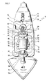
- Fig. 1 eine teilweise geschnittene perspektivische Gesamtansicht einer ersten Variante einer ersten Konzeption der erfindungsgemäßen Lösung;
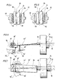
- Fig. 2 einen Schnitt längs Linie 2-2 in Fig. 1;
- Fig. 3 einen Schnitt längs Linie 3-3 in Fig. 2;
- Fig. 4 einen Schnitt längs Linie 4-4 in Fig. 3 bei einem Ausführungsbeispiel;
- Fig. 5 eine Darstellung ähnlich Fig. 4 bei einem weiteren Ausführungsbeispiel;
- Fig. 6 eine ausschnittweise Darstellung ähnlich Fig. 2 einer zweiten Variante der ersten Konzeption;
- Fig. 7 eine Darstellung ähnlich Fig. 3 der zweiten Variante;
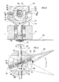
- Fig. 8 eine teilweise geschnittene Frontansicht einer ersten Variante einer zweiten Konzeption;
- Fig. 9 einen Schnitt längs Linie 9-9 in Fig.8;
- Fig.10 eine zweite Variante der zweiten Konzeption in Draufsicht ähnlich Fig. 9;
- Fig. 11 eine teilweise geschnittene Draufsicht auf eine dritte Variante der zweiten Konzeption und
- Fig. 12 eine teilweise geschnittene ausschnittsweise Darstellung einer Seitenansicht der dritten Variante gemäß Fig. 11.
- Figure 1 is a partially sectioned overall perspective view of a first variant of a first concept of the solution according to the invention.
- Fig. 2 is a section along line 2-2 in Fig. 1;
- Fig. 3 is a section along line 3-3 in Fig. 2;
- 4 shows a section along line 4-4 in FIG. 3 in one exemplary embodiment;
- 5 shows a representation similar to FIG. 4 in a further exemplary embodiment;
- FIG. 6 is a partial illustration similar to FIG. 2 of a second variant of the first concept;
- FIG. 7 shows a representation similar to FIG. 3 of the second variant;
- 8 is a partially sectioned front view of a first variant of a second concept;
- 9 shows a section along line 9-9 in FIG. 8;
- 10 shows a second variant of the second concept in plan view similar to FIG. 9;
- Fig. 11 is a partially sectioned plan view of a third variant of the second concept and
- FIG. 12 shows a partially sectioned illustration of a side view of the third variant according to FIG. 11.
Eine in Fig. 1 als Ganzes mit 10 bezeichnete erste Variante einer ersten Konzeption eines erfindungsgemäßen Oszillationsantriebs umfaßt einen als Ganzes mit 12 bezeichneten Motor, welcher, wie in Fig. 2 und 3 dargestellt, eine Antriebswelle 14 treibt, welche auf ihrem vorderen Ende ein Exzenterrad 16 trägt. Dieses Exzenterrad 16 ist koaxial zu einer Antriebswellenachse 18 angeordnet und weist eine gegenüber der Antriebswellenachse 18 exzentrisch versetzt angeordnete kreiszylindrische Ausnehmung 20 auf, deren Achse 22 parallel zur Antriebswellenachse 18 ausgerichtet ist.A first variant, designated as a whole in FIG. 1 by 10, of a first concept of an oscillation drive according to the invention comprises a motor, designated as a whole as 12, which, as shown in FIGS. 2 and 3, drives a
In diese Ausnehmung 20 ist ein Pendellager 24 eingesetzt, welches einen Lageraußenring 26 aufweist, dessen innere Ringflächen 28 in der Art eines ringförmigen Ausschnitts aus einer Hohlkugel geformt sind, so daß auf dieser Ringfläche laufende Wälzkörper 30, die sich ihrerseits auf einem Lagerinnenring 32 in in dessen Außenmantel eingearbeiteten Führungsrinnen 34 abstützen, insgesamt ein Kippen des Lagerinnenrings 32 gegenüber der Achse 22 um einen Kugelmittelpunkt der hohlkugelförmig ausgebildeten inneren Ringfläche 28 des Lageraußenrings 26 erlaubt, welcher auf der Achse 22 liegt. Ein Kippwinkel, bezogen auf die Achse 22, liegt vorzugsweise im Bereich von < 5°, woraus ein maximaler Kippbereich von < 10° resultiert.In this
Vorzugsweise liegt der Kugelmittelpunkt der inneren Ringfläche 28 im Schnittpunkt einer senkrecht auf der Achse 22 stehenden und eine Symmetrieebene des Pendellagers 24 bildenden Lagerebene 36 mit der Achse 22, so daß die beiden Kippachsen, um welche der Lagerinnenring 32 gegenüber dem Lageraußenring 26 verkippbar ist, in der Lagerebene 36 liegen.Preferably, the center of the sphere of the
Der Lagerinnenring 32 weist eine in seiner nicht gekippten Stellung mit der Achse 22 koaxiale Aufnahmebohrung 38 auf. In diese greift ein Zapfen 40 eines Arms 42 ein, welcher die zur Antriebswellenachse 18 exzentrischen Bewegungen der Aufnahmebohrung auf eine Werkzeugantriebswelle 44 überträgt. Die Werkzeugantriebswelle 44 ist in einem das Exzenterrad 16, den Arm 42 und einen oberen Abschnitt 48 umschließenden Getriebegehäuse 46 zweifach gelagert, nämlich im Bereich eines Unterteils 50 und im Bereich eines Oberteils 52 des Getriebegehäuses 46.The bearing
Wie in Fig. 1 dargestellt, erstreckt sich ein unterer Abschnitt 54 der Werkzeugantriebswelle 44 über das Getriebehäuse 46 hinaus und trägt beispielsweise ein Schleifwerkzeug 56. Anstelle dieses Schleifwerkzeugs 56 ist es jedoch ebenfalls denkbar, beispielsweise eine Schneidklinge gemäß dem europäischen Patent 0 174 427 einzusetzen.As shown in FIG. 1, a
Vorzugsweise ist die Werkzeugantriebswelle 44 so angeordnet, daß deren Achse 58 senkrecht auf der Antriebswellenachse 18 steht und diese schneidet.The
Im oberen Abschnitt 48 der Werkzeugantriebswelle ist ein diese umschließender Lagerblock 60 vorgesehen, welcher zwei in entgegengesetzte Richtungen von diesem abstehende Lagerzapfen 62 trägt, die eine die Achse 58 schneidende und vorzugsweise senkrecht auf dieser stehende Schwenkachse 64 bilden, um welche der Arm 42 verschwenkbar ist.Provided in the
Der Lagerblock 60 und der Arm 42 bilden somit ein Schwenkelement, wobei der Arm 42 einen an dem Pendellager 24 als Verbindungsglied angreifenden Teil des Schwenkelements darstellt. Der Abstand der Achse 58 von der Aufnahmebohrung 38 und die Exzentrizität derselben, d.h. deren Abstand von der Antriebswellenachse, sind dabei so bemessen, daß bei rotierendem Exzenterrad 16 an dem Pendellager 24 Kippwinkel von < 5° auftreten.The bearing
Besonders bevorzugt ist eine Lösung, bei welcher die Schwenkachse 64 sowohl die Achse 58 als auch die Antriebswellenachse 18 in deren Schnittpunkt schneidet und so ausgerichtet ist, daß die oszillierenden Bewegungen der Werkzeugantriebswelle 44 symmetrisch zu einer senkrecht auf der Antriebswellenachse 18 stehenden und durch die Achse 58 hindurchverlaufenden Mittelebene 66 erfolgende Bewegungen der Schwenkachse 64 bewirken.A particularly preferred solution is one in which the
Erfindungsgemäß ist bei der ersten Varianten, dargestellt in den Fig. 2 und 3, der Arm 42 gabelförmig ausgebildet, so daß jeweils ein Schenkel 68 des Arms 42 zu einem der Lagerzapfen 62 reicht. Im einfachsten Fall haben die Schenkel keine den Lagerzapfen 62 vollkommen umschließende Lagerbohrung, sondern lediglich eine den jeweiligen Lagerzapfen 62 U-förmig umgreifende Aussparung 70, welche zu einem dem Zapfen 40 gegenüberliegenden Ende 72 des jeweiligen Schenkels 68 hin offen ist.According to the invention, in the first variant, shown in FIGS. 2 and 3, the
Zwischen den beiden Schenkeln 68 des Arms 42 erstreckt sich ein an den Lagerblock 60 angeformter Finger 74, welcher auf einander gegenüberliegenden Seiten jeweils eine dem jeweiligen Schenkel 68 zugewandte Führungsfläche 76 aufweist, an welchem der jeweilige Schenkel 68 des Arms 42 geführt ist.Extending between the two
Vorzugsweise sind, wie in den Fig. 4 und 5 dargestellt, in einem dem Zapfen 40 zugewandten Endbereich im Bereich der Führungsflächen 76 auf diesen Führungsflächen 76 aufliegende Gleitelemente vorgesehen, welche entweder in Ausnehmungen 78 der Schenkel 68 gehaltene Wälzkörper 80 oder in diesen Ausnehmungen 78 gehaltene Gleitkörper 82 sein können, wobei die Gleitkörper 82 vorzugsweise aus Teflon hergestellt sind. Es ist aber auch denkbar, zwischen dem Finger 74 und den Schenkeln 68 andere Flachbahn ührungen vorzusehen.4 and 5, in an end region facing the
Zweckmäßigerweise ist die Anordnung des Fingers 74 und des Zapfens 40 so gewählt, daß diese symmetrisch zu einer durch die Achse 58 der Werkzeugantriebswelle hindurchgehende Symmetrieebene 84 ausgebildet sind, wobei die Symmetrieebene 84 gemeinsam mit dem Arm 42 und dem Finger 74 hin- und heroszilliert.The arrangement of the
Um eine exakte Führung zwischen den Schenkeln 68 und dem Finger 74 zu erreichen, ist es vorteilhaft, wenn die Wälzkörper 80 oder die Gleitkörper 82 mit einer bestimmten Kraft vorgespannt sind, so daß kein Spiel zwischen dem Finger 74 und dem Schenkel 68 besteht. Zu diesem Zweck ist der Finger 74 mit einem diesen parallel zur Symmetrieebene 84 durchsetzenden Schlitz 86 versehen, der dem Finger senkrecht zu der Symmetrieebene 84 eine Querelastizität verleiht, so daß dieser als elastischer Kraftspeicher zur Beaufschlagung der Wälzkörper 80 oder der Gleitkörper 82 dienen kann. Vorteilhafterweise ist auch der Schlitz 86 symmetrisch zur Symmetrieebene 84 ausgebildet.In order to achieve an exact guidance between the
Um die Möglichkeit zu schaffen, daß sich der Zapfen 40 an einem senkrecht zur Achse 22 verlaufenden Boden 88 der Ausnehmung 20 abstützen kann, ist ein diesem Boden 88 zugewandtes Ende des Zapfens 40 mit einer Kugel 90 versehen, welche lose in einer entsprechenden Ausnehmung des Zapfens 40 liegt, so daß sich die Kugel 90 auf dem Boden 88 abrollen kann.To create the possibility that the
Eine gegenüber der ersten Variante vereinfachte zweite Variante, dargestellt in den Fig. 6 und 7, ist insoweit als dieselben Teile Verwendung finden, mit denselben Bezugszeichen versehen, so daß diesbezüglich auf die Ausführungen zur ersten Variante Bezug genommen wird.A simplified second variant compared to the first variant, shown in FIGS. 6 and 7, is provided with the same reference numerals insofar as the same parts are used, so that reference is made in this regard to the explanations for the first variant.
Bei diesem zweiten Ausführungsbeispiel erstreckt sich die Werkzeugantriebswelle 44′ nicht durch das Getriebegehäuse 46′ hindurch, sondern ist lediglich im Bereich des Unterteils 50′ gelagert, wobei der obere Abschnitt 48′ ein in das Getriebegehäuse 46′ hineinragender Wellenstummel ist.In this second embodiment, the tool drive shaft 44 'does not extend through the gear housing 46', but is only supported in the region of the lower part 50 ', the upper section 48' being a shaft stub projecting into the gear housing 46 '.
Darüberhinaus ist der Arm 42′ im Gegensatz zur ersten Variante nicht aus starrem Material, sondern aus Material, welches in Richtung parallel zur Achse 58′ der Werkzeugantriebswelle 44′ auf und ab federn kann, so daß der Zapfen 40 in der Symmetrieebene 84 auf- und abschwenkbar ist, während zwischen dem Zapfen 40 und dem oberen Abschnitt 48′ der Werkzeugantriebswelle 44′ in Richtung senkrecht zur Symmetrieebene 84 eine starre Verbindung beseht.In addition, the arm 42 'in contrast to the first variant is not made of rigid material, but of material which can spring up and down in the direction parallel to the axis 58' of the tool drive shaft 44 ', so that the
Hierfür ist der Arm 42′ vorzugsweise aus einem Federplättchen gebildet, welches in Richtung senkrecht zur Symmetrieebene eine wesentlich größere Breitenausdehnung als in seiner parallel zur Symmetrieebene 84 gemessenen Dicke hat.For this purpose, the arm 42 'is preferably formed from a spring plate, which is in the direction perpendicular to the plane of symmetry has a substantially greater width than in its thickness measured parallel to the plane of
Darüberhinaus ist, um im wesentlichen eine Bewegung des Zapfens 40 auf einer Kegelbahn zu gewährleisten, das den Arm 42′ bildende Federplättchen auf einer dem Exzenterrad 16 entgegengesetzten Seite des oberen Abschnitts 48′ der Werkzeugantriebswelle 44′ zwischen zwei den Lagerblock 60′ bildenden Klemmstücken 92 und 94 eingespannt, wobei das Klemmstück 94 fest an dem oberen Abschnitt 48′ der Werkzeugantriebswelle 44′ gehalten ist.In addition, to ensure essentially movement of the
Bei einer ersten Variante einer zweiten Konzeption der Erfindung, dargestellt in den Fig. 8 und 9, trägt die Antriebswelle 100 ein als Ganzes mit 102 bezeichnetes Taumellager, welches ein auf der Antriebswelle 100 sitzendes Lagerinnenteil 104 mit einer um die Antriebswelle 100 umlaufenden Kreisbahn 106 trägt, deren Mittelpunkt auf der Antriebswellenachse 108 liegt, deren Bahnebene 110 jedoch einen Winkel mit der Antriebswellenachse einschließt, welcher vorzugsweise in einem Bereich zwischen 85 bis 90° liegt. Diese Kreisbahn 106 ist als Umlaufbahn für Wälzkörper 112 des Taumellagers 102 ausgebildet, welche ihrerseits wiederum in einem Lageraußenring 114 laufen, so daß der Lageraußenring durch die Wälzkörper 112 in der Bahnebene 110 gegenüber dem Lagerinnenteil 104 drehbar ist.In a first variant of a second concept of the invention, shown in FIGS. 8 and 9, the
Wenn nun das drehfest mit der Antriebswelle 100 verbundene Lagerinnenteil mit dieser rotiert, so führt die Bahnebene 110 Taumelbewegungen um die Antriebswellenachse 108 durch, wobei durch die freie Drehbarkeit des Lageraußenrings 114 gegenüber dem Lagerinnenteil 104 ersterer sich nicht mit der Antriebswelle 100 mitzudrehen braucht.If the inner bearing part rotatably connected to the
Der Lageraußenring 114 ist seinerseits in einer Fassung 116 gehalten, welche auf gegenüberliegenden Seiten und koaxial zueinander angeordnete Stifte 118 aufweist, die gemeinsam eine Schwenkachse 120 bilden, die vorzugsweise durch den Mittelpunkt der Kreisbahn 106 hindurchverläuft und in diesem auch die Antriebswellenachse 108 schneidet. Die Stifte 118 sind in einer die Fassung 116 umgreifenden Gabel 122 gelagert, welche ihrerseits drehfest mit der Werkzeugantriebswelle 124 verbunden ist. Die Achse 126 der Werkzeugantriebswelle 124 verläuft dabei vorzugsweise senkrecht zur Antriebswellenachse 124 und durch den Mittelpunkt der Kreisbahn 106.The bearing
Ein Drehen der Antriebswelle 100 führt nun dazu, daß sich das Lagerinnenteil 104 mit dieser mitdreht und somit die Bahnebene 110 Taumelbewegungen durchführt. Der gegenüber dem Lagerinnenteil 104 drehbare Lageraußenring 114 dreht sich dabei nicht, sondern führt lediglich die Taumelbewegungen durch, wobei durch die in der Bahnebene 110 verlaufende Schwenkachse 120 sämtliche Kippbewegungen um diese nicht auf die Gabel 122 übertragen werden, sondern lediglich die Kippbewegungen um die Achse 126, so daß letztendlich die Gabel 122 eine schwenkoszillierende Bewegung um die Achse 126 mit einem Schwenkwinkel durchführt, der der doppelten Differenz zwischen einem rechten Winkel und dem Neigungswinkel der Bahnebene 110 zur Antriebswellenachse 108 entspricht.Rotation of the
Als Werkzeug ist in den Fig. 8 und 9 ein Schneidmesser 128 dargestellt. Es kann jedoch auch ein in Fig. 1 dargestelltes Schleifwerkzeug 56 an der Werkzeugantriebswelle 124 montiert sein.A cutting
Bei einer zweiten Variante der zweiten Konzeption, dargestellt in Fig. 10, sind dieselben Teile wie bei der ersten Variante mit denselben Bezugszeichen versehen, so daß hinsichtlich deren Beschreibung auf die Ausführungen zur ersten Variante verwiesen werden kann.In a second variant of the second concept, shown in FIG. 10, the same parts as in the first variant are provided with the same reference numerals, so that reference can be made to the explanations for the description of the first variant with regard to their description.
Bei dieser zweiten Variante treibt eine Motorwelle 130 über zwei Zahnräder 132, 134 die Antriebswelle 100′, auf welcher das Taumellager 102′ sitzt. Das Lagerinnenteil 104′ ist jedoch nicht, wie bei der ersten Variante, fest auf der Antriebswelle 100′ angeordnet, sondern lediglich drehfest, und ist daher in Richtung der Antriebswellenachse 108′ auf der Antriebswelle 100′ verschieblich. Zur drehfesten Verbindung zwischen der Antriebswelle 100′ und dem Lagerinnenteil 104′ ist die Antriebswelle 100′ mit einer Keilverzahnung 136 versehen, welche in entsprechende Nuten im Lagerinnenteil 104′ eingreift.In this second variant, a
Der Lageraußenring 114′ ist mit einem sich radial von diesem weg erstreckenden Stab 138 versehen, welcher eine drehfest mit der Werkzeugantriebswelle 124′ verbundene Stabführung 140 durchgreift, in welcher der Stab 138 um seine Stabachse 142 drehbar und in Längsrichtung der Stabachse 142 verschiebbar gelagert ist. Vorzugsweise ist der Stab 138 hierbei kreiszylindrisch ausgebildet und die Stabachse 142 ist ebenfalls so ausgerichtet, daß sie senkrecht zur Achse 126′ der Werkzeugantriebswelle 124′ verläuft und diese schneidet. Ferner liegt die Stabachse 142 zweckmäßigerweise in der Bahnebene 110′ des Taumellagers 102′ und schneidet die Antriebswellenachse 108′.The bearing outer ring 114 'is provided with a
Zum Massenausgleich ist an einem dem Lageraußenring 114′ entgegengesetzten Ende des Stabs 138 ein Ausgleichsgewicht 139 vorgesehen, welches für einen ruhigeren Lauf der zweiten Variante notwendig ist.To balance the mass, a
Dreht sich nun die Antriebswelle 100′, so führt das Taumellager 102′ ebenfalls Taumelbewegungen aus, wobei sämtliche Schwenkbewegungen um die Stabachse 142 frei erfolgen können. Da außerdem die Stabführung 140 um die Achse 126′ der Werkzeugantriebswelle 124′ drehbar ist, kann der Stab 138 zusätzlich auch noch um diese Achse verschwenken, wozu sich das Taumellager 102′ auf der Antriebswelle 100′ zwischen seiner durchgezogen gezeichneten Stellung und seiner strichpunktiert gezeichneten Stellung in Fig. 10 auf- und abbewegen können muß. Zum Ausgleich des unterschiedlichen Abstandes des Kreismittelpunkts der Kreisbahn 106′ von der Achse 126′ ist es erforderlich, daß der Stab 138 in Richtung der Stabachse 142 in der Stabführung 140 gleitend gelagert ist.If the drive shaft 100 'now rotates, the wobble bearing 102' also performs wobble movements, with all pivoting movements about the
Bei einer dritten Variante der zweiten Konzeption, dargestellt in den Fig. 11 und 12, ist direkt auf der Antriebswelle 150 eine Taumelscheibe 152 montiert, welche eine Frontfläche 154 aufweist, die in radialer Richtung zur Antriebswellenachse 156 stets parallel zu einer senkrecht auf dieser Antriebswellenachse 156 stehenden Ebene 158 verläuft, jedoch im Verlauf eines Bahnumlaufs einen bis zu einem halben Umlauf zunehmenden und anschließend wieder auf Null abnehmenden Abstand von dieser Ebene 158 aufweist.In a third variant of the second concept, shown in FIGS. 11 and 12, a
Auf dieser Frontfläche 154 liegen in einem Käfig 160 geführte und mit ihren Rotationsachsen radial zur Antriebswellenachse 156 ausgerichtete Wälzkörper 162 an, welche auf ihrer der Frontfläche 154 gegenüberliegenden Seite eine Druckscheibe 164 beaufschlagen. Sowohl der Käfig 160 als auch die Druckscheibe 164 besitzen jeweils eine zentrale Ausnehmung 166 bzw. 168, mit welchen sie auf einem über die Frontfläche 154 überstehenden und zur Antriebswelle 150 koaxialen Wellenstummel 170 geführt sind, sich jedoch nicht mit dem Wellenstummel 170 mitdrehen. Der Käfig 160 und die Druckscheibe 164 sind gegenüber dem Wellenstummel 70 kippbar, so daß es ihnen möglich ist, den Bewegungen der Wälzkörper 162 in Richtung der Antriebswellenachse 156 zu folgen und dabei ebenfalls Bewegungen in dieser Richtung durchzuführen.
Die Druckscheibe 164 liegt mit einer den Wälzkörpern 162 gegenüberliegenden Druckfläche 172 an einem fest mit der Werkzeugantriebswelle 174 verbundenen Schwenkteil 176 an, welches mit der Werkzeugantriebswelle 174 um dessen Achse 178 drehbar ist, wobei vorzugsweise die Achse 178 senkrecht zur Antriebswellenachse 156 verläuft. Eine der Druckfläche 172 der Druckscheibe 164 zugewandte Anlagefläche 180 des Schwenkteils 176 ist dabei so ausgebildet, daß sie eine geradlinig verlaufende Kante 182 aufweist, welche die Antriebswellenachse 156 schneidet und vorzugsweise senkrecht auf der Achse 178 steht. Beiderseits der Kante 182 ist die Auflagefläche 180 in Richtung auf die Achse 178 abgeschrägt, so daß die Kante 182 der am weitesten in Richtung der Druckfläche 172 vorspringende Bereich der Auflagefläche 180 ist. Die Abschrägung ist dabei so gewählt, daß sie beiderseits der Kante 182 ein Verkippen der Druckscheibe 164 um eine von der Kante 182 gebildete Kippachse erlaubt, welches bei rotierender Antriebswelle 150 durch die Taumelscheibe 152 und die durch deren Frontfläche 154 beaufschlagten Wälzkörper 162 hervorgerufen wird.The
Allein ein Verkippen der Druckscheibe 164 um eine zur Achse 178 der Werkzeugantriebswelle 174 parallele Achse führt zu einer Beaufschlagung der Auflagefläche 180 durch die Druckfläche 172 im Bereich der Kante 182 und somit gleichzeitig zu einem Verschwenken des Schwenkteils 176 um die Achse 178. Dadurch wird bei rotierender Taumelscheibe 152 eine Schwenkbewegung um die Achse 178 auf das Schwenkteil 176 übertragen, welches seinerseits über die Werkzeugantriebswelle 174 beispielsweise ein Schneidwerkzeug 184 ebenfalls oszillierend verschwenkt.Tilting the
Claims (38)
Applications Claiming Priority (2)
| Application Number | Priority Date | Filing Date | Title |
|---|---|---|---|
| DE3840974A DE3840974A1 (en) | 1988-12-06 | 1988-12-06 | OSCILLATION DRIVE |
| DE3840974 | 1988-12-06 |
Publications (3)
| Publication Number | Publication Date |
|---|---|
| EP0372376A2 true EP0372376A2 (en) | 1990-06-13 |
| EP0372376A3 EP0372376A3 (en) | 1990-11-28 |
| EP0372376B1 EP0372376B1 (en) | 1993-05-12 |
Family
ID=6368503
Family Applications (1)
| Application Number | Title | Priority Date | Filing Date |
|---|---|---|---|
| EP89122051A Expired - Lifetime EP0372376B1 (en) | 1988-12-06 | 1989-11-29 | Oscillating device |
Country Status (4)
| Country | Link |
|---|---|
| EP (1) | EP0372376B1 (en) |
| JP (1) | JPH06100253B2 (en) |
| KR (1) | KR930000570B1 (en) |
| DE (2) | DE3840974A1 (en) |
Cited By (19)
| Publication number | Priority date | Publication date | Assignee | Title |
|---|---|---|---|---|
| EP0610801A1 (en) * | 1993-02-04 | 1994-08-17 | Robert Bosch Gmbh | Handtool for machining surfaces |
| EP0623422A1 (en) * | 1993-05-05 | 1994-11-09 | C. & E. FEIN GmbH & Co. | Electrical tool |
| EP0631843A1 (en) * | 1993-07-01 | 1995-01-04 | Black & Decker Inc. | Two plane oscillating sander |
| EP0655023A1 (en) * | 1992-08-14 | 1995-05-31 | Ryobi Motor Products Corp. | Detail sander |
| WO1997014531A1 (en) * | 1995-10-18 | 1997-04-24 | Ab Dentatus | Hand-held apparatus for sideways driving of a tool |
| US5626510A (en) * | 1993-02-04 | 1997-05-06 | Robert Bosch Gmbh | Power tool for surface treatment |
| EP0799675A1 (en) * | 1996-04-02 | 1997-10-08 | S.P. Air Kabusiki Kaisha | Power abrading tool |
| US6158528A (en) * | 2000-01-27 | 2000-12-12 | S.P. Air Kabusiki Kaisha | Hand-held pneumatic rotary drive device |
| US6179696B1 (en) | 1998-04-29 | 2001-01-30 | Black & Decker Inc. | Powered oscillating hand tool |
| US6443239B1 (en) | 2000-02-29 | 2002-09-03 | S.P. Air Kabusiki Kaisha | Pneumatic rotary tool |
| EP1358965A2 (en) * | 2002-04-30 | 2003-11-05 | C. & E. Fein Gmbh & Co. KG | Drive arrangement for oscillating spindle |
| EP1358964A1 (en) * | 2002-04-30 | 2003-11-05 | C. & E. Fein Gmbh & Co. KG | Oscillations generator |
| US6796386B2 (en) | 2000-09-08 | 2004-09-28 | S.P. Air Kabusiki Kaisha | Pneumatic rotary tool |
| GB2408708A (en) * | 2003-12-01 | 2005-06-08 | Bosch Gmbh Robert | Hand-held machine tool |
| US7404450B2 (en) | 2000-01-27 | 2008-07-29 | S.P. Air Kabusiki Kaisha | Pneumatic rotary tool |
| WO2009089940A1 (en) * | 2008-01-16 | 2009-07-23 | Robert Bosch Gmbh | Motor-driven machine tool |
| WO2014105943A1 (en) * | 2012-12-31 | 2014-07-03 | Robert Bosch Gmbh | Wobble drive for an oscillating tool |
| CN103939549A (en) * | 2013-01-22 | 2014-07-23 | 陈伯均 | Conical movement link mechanism |
| US20180015567A1 (en) * | 2016-07-13 | 2018-01-18 | Lawrence Livermore National Security, Llc | Direct writing nozzle system for additive manufacturing |
Families Citing this family (20)
| Publication number | Priority date | Publication date | Assignee | Title |
|---|---|---|---|---|
| US5533926A (en) * | 1992-09-04 | 1996-07-09 | Ryobi North America | Sandpaper pad and pad support for a detail sander |
| US5637034A (en) * | 1993-08-13 | 1997-06-10 | Ryobi North America, Inc. | Detail sander |
| DE4344849A1 (en) * | 1993-12-29 | 1995-07-06 | Fein C & E | Machine tool |
| US5607343A (en) * | 1994-08-22 | 1997-03-04 | Ryobi North America | Sander vibration isolator |
| US5759094A (en) | 1995-02-09 | 1998-06-02 | Porter-Cable Corporation | In-line detail sander |
| US5743791A (en) * | 1995-02-09 | 1998-04-28 | Porter Cable Corporation | Sanding system |
| DE10164081B4 (en) * | 2001-12-19 | 2012-01-26 | C. & E. Fein Gmbh | Oscillating tool with compensation section |
| US6926595B2 (en) | 2002-04-30 | 2005-08-09 | C.&E. Fein Gmbh & Co. Kg | Oscillatory drive |
| DE202009011312U1 (en) | 2009-08-11 | 2010-12-23 | C. & E. Fein Gmbh | Hand tool with an oscillation drive |
| US8365419B2 (en) * | 2009-09-29 | 2013-02-05 | Robert Bosch Gmbh | Accessory attachment system for an oscillating power tool |
| DE102011015117A1 (en) * | 2011-03-22 | 2012-09-27 | C. & E. Fein Gmbh | hand tool |
| JP2013031906A (en) * | 2011-08-02 | 2013-02-14 | Makita Corp | Oscillating-rotary-type electric tool |
| DE102013100085A1 (en) * | 2013-01-07 | 2014-07-10 | C. & E. Fein Gmbh | Oscillating powered machine tool |
| DE102013002727A1 (en) | 2013-02-16 | 2014-08-21 | Heule Werkzeug Ag | Drive device for exercising a push and turn movement on a drive shaft for driving a deburring tool and method for operation |
| US10252441B2 (en) | 2013-08-28 | 2019-04-09 | Corning Incorporated | System and method for cutting a wet green ceramic article |
| DE102014102128A1 (en) * | 2014-02-19 | 2015-08-20 | C. & E. Fein Gmbh | oscillatory |
| DE102015226029A1 (en) * | 2015-12-18 | 2017-06-22 | Robert Bosch Gmbh | Motor-driven hand tool machine |
| FR3059264B1 (en) * | 2016-11-29 | 2019-05-10 | Mure Et Peyrot | ELECTRIC KNIFE |
| WO2020175009A1 (en) * | 2019-02-28 | 2020-09-03 | 工機ホールディングス株式会社 | Work machine |
| CN110722607B (en) * | 2019-10-18 | 2021-08-31 | 苏州劲山电动工具有限公司 | Structure for balancing vibration of high-frequency swinging mechanism of handheld tool |
Citations (7)
| Publication number | Priority date | Publication date | Assignee | Title |
|---|---|---|---|---|
| DE143844C (en) * | ||||
| US2639620A (en) * | 1950-10-16 | 1953-05-26 | Frank L Bamford | Reciprocator |
| US2697897A (en) * | 1950-01-12 | 1954-12-28 | Peninsula Tool Company Inc | Rubbing machine |
| US3740847A (en) * | 1971-02-04 | 1973-06-26 | W Kliever | Power driven meat trimming and cutting knife |
| DE8031084U1 (en) * | 1981-07-23 | C. & E. Fein Gmbh & Co, 7000 Stuttgart | Power tool with oscillating tool drive | |
| EP0035805A2 (en) * | 1980-02-20 | 1981-09-16 | Officine Meccaniche Ferrari Fernando S.p.A. | Control unit for cutter bars in general |
| SU896294A1 (en) * | 1980-03-19 | 1982-01-07 | Предприятие П/Я В-8721 | Apparatus for converting rotation to oscillatory motion |
Family Cites Families (3)
| Publication number | Priority date | Publication date | Assignee | Title |
|---|---|---|---|---|
| CH532139A (en) * | 1972-03-02 | 1972-12-31 | Mueller Jakob | Device for converting a rotary movement into an oscillating movement in narrow weaving machines |
| DE3430562C1 (en) * | 1984-08-20 | 1985-11-21 | Braun Ag, 6000 Frankfurt | Apparatus for converting a rotary motion into a reciprocating motion |
| DE8529622U1 (en) * | 1985-10-18 | 1986-01-23 | Chicago Pneumatic Zweigniederlassung der Chicago Pneumatic Tool Co. (West Germany), 6222 Geisenheim | Drive for an oscillating tool |
-
1988
- 1988-12-06 DE DE3840974A patent/DE3840974A1/en not_active Ceased
-
1989
- 1989-11-29 EP EP89122051A patent/EP0372376B1/en not_active Expired - Lifetime
- 1989-11-29 DE DE8989122051T patent/DE58904346D1/en not_active Expired - Fee Related
- 1989-12-05 JP JP1314466A patent/JPH06100253B2/en not_active Expired - Lifetime
- 1989-12-06 KR KR1019890018098A patent/KR930000570B1/en not_active IP Right Cessation
Patent Citations (7)
| Publication number | Priority date | Publication date | Assignee | Title |
|---|---|---|---|---|
| DE143844C (en) * | ||||
| DE8031084U1 (en) * | 1981-07-23 | C. & E. Fein Gmbh & Co, 7000 Stuttgart | Power tool with oscillating tool drive | |
| US2697897A (en) * | 1950-01-12 | 1954-12-28 | Peninsula Tool Company Inc | Rubbing machine |
| US2639620A (en) * | 1950-10-16 | 1953-05-26 | Frank L Bamford | Reciprocator |
| US3740847A (en) * | 1971-02-04 | 1973-06-26 | W Kliever | Power driven meat trimming and cutting knife |
| EP0035805A2 (en) * | 1980-02-20 | 1981-09-16 | Officine Meccaniche Ferrari Fernando S.p.A. | Control unit for cutter bars in general |
| SU896294A1 (en) * | 1980-03-19 | 1982-01-07 | Предприятие П/Я В-8721 | Apparatus for converting rotation to oscillatory motion |
Non-Patent Citations (1)
| Title |
|---|
| Soviet Inventions Illustrated, Derwent Publications Ltd., Sektion Mechanik, Woche J47, Zusammenfassung, Nr.A1944, Q64, 12.Januar 1& SU-A-896294 (PIVOVARENOK A M) 7.Januar 1982 . * |
Cited By (34)
| Publication number | Priority date | Publication date | Assignee | Title |
|---|---|---|---|---|
| EP0655023A1 (en) * | 1992-08-14 | 1995-05-31 | Ryobi Motor Products Corp. | Detail sander |
| EP0655023A4 (en) * | 1992-08-14 | 1995-10-25 | Ryobi Motor Products Corp | Detail sander. |
| US5626510A (en) * | 1993-02-04 | 1997-05-06 | Robert Bosch Gmbh | Power tool for surface treatment |
| EP0610801A1 (en) * | 1993-02-04 | 1994-08-17 | Robert Bosch Gmbh | Handtool for machining surfaces |
| EP0623422A1 (en) * | 1993-05-05 | 1994-11-09 | C. & E. FEIN GmbH & Co. | Electrical tool |
| US5441450A (en) * | 1993-05-05 | 1995-08-15 | C.&E. Fein Gmbh & Co. | Power tool having means to switch from oscillatory movement to rotary movement |
| EP0631843A1 (en) * | 1993-07-01 | 1995-01-04 | Black & Decker Inc. | Two plane oscillating sander |
| US5993304A (en) * | 1995-10-18 | 1999-11-30 | Ab Dentatus | Hand-held apparatus for sideways driving of a tool |
| WO1997014531A1 (en) * | 1995-10-18 | 1997-04-24 | Ab Dentatus | Hand-held apparatus for sideways driving of a tool |
| EP0799675A1 (en) * | 1996-04-02 | 1997-10-08 | S.P. Air Kabusiki Kaisha | Power abrading tool |
| US5919085A (en) * | 1996-04-02 | 1999-07-06 | S.P. Air Kabusiki Kaisha | Power abrading tool having dust abatement feature |
| US6179696B1 (en) | 1998-04-29 | 2001-01-30 | Black & Decker Inc. | Powered oscillating hand tool |
| USRE40345E1 (en) * | 1998-04-29 | 2008-05-27 | Black & Decker, Inc. | Powered oscillating hand tool |
| US6158528A (en) * | 2000-01-27 | 2000-12-12 | S.P. Air Kabusiki Kaisha | Hand-held pneumatic rotary drive device |
| US7404450B2 (en) | 2000-01-27 | 2008-07-29 | S.P. Air Kabusiki Kaisha | Pneumatic rotary tool |
| USRE39009E1 (en) * | 2000-01-27 | 2006-03-14 | S.P. Air Kabusiki Kaisha | Hand-held pneumatic rotary drive device |
| US6443239B1 (en) | 2000-02-29 | 2002-09-03 | S.P. Air Kabusiki Kaisha | Pneumatic rotary tool |
| US6796386B2 (en) | 2000-09-08 | 2004-09-28 | S.P. Air Kabusiki Kaisha | Pneumatic rotary tool |
| EP1358965A3 (en) * | 2002-04-30 | 2004-04-07 | C. & E. FEIN GmbH | Drive arrangement for oscillating spindle |
| DE10220325B4 (en) * | 2002-04-30 | 2011-06-01 | C. & E. Fein Gmbh | oscillatory |
| EP1358965A2 (en) * | 2002-04-30 | 2003-11-05 | C. & E. Fein Gmbh & Co. KG | Drive arrangement for oscillating spindle |
| EP1358964A1 (en) * | 2002-04-30 | 2003-11-05 | C. & E. Fein Gmbh & Co. KG | Oscillations generator |
| US7108077B2 (en) | 2003-12-01 | 2006-09-19 | Robert Bosch Gmbh | Power tool |
| GB2408708A (en) * | 2003-12-01 | 2005-06-08 | Bosch Gmbh Robert | Hand-held machine tool |
| GB2408708B (en) * | 2003-12-01 | 2005-11-16 | Bosch Gmbh Robert | Hand-held machine tool |
| WO2009089940A1 (en) * | 2008-01-16 | 2009-07-23 | Robert Bosch Gmbh | Motor-driven machine tool |
| RU2484939C2 (en) * | 2008-01-16 | 2013-06-20 | Роберт Бош Гмбх | Processing machine drive by engine |
| US8720162B2 (en) | 2008-01-16 | 2014-05-13 | Robert Bosch Gmbh | Motor-driven machine tool |
| CN101909815B (en) * | 2008-01-16 | 2014-10-15 | 罗伯特·博世有限公司 | Motor-driven machine tool |
| WO2014105943A1 (en) * | 2012-12-31 | 2014-07-03 | Robert Bosch Gmbh | Wobble drive for an oscillating tool |
| US9561569B2 (en) | 2012-12-31 | 2017-02-07 | Robert Bosch Tool Corporation | Wobble drive for an oscillating tool |
| CN103939549A (en) * | 2013-01-22 | 2014-07-23 | 陈伯均 | Conical movement link mechanism |
| US20180015567A1 (en) * | 2016-07-13 | 2018-01-18 | Lawrence Livermore National Security, Llc | Direct writing nozzle system for additive manufacturing |
| US10730138B2 (en) * | 2016-07-13 | 2020-08-04 | Lawrence Livermore National Security, Llc | Direct writing nozzle system for additive manufacturing |
Also Published As
| Publication number | Publication date |
|---|---|
| EP0372376A3 (en) | 1990-11-28 |
| JPH02209653A (en) | 1990-08-21 |
| DE58904346D1 (en) | 1993-06-17 |
| DE3840974A1 (en) | 1990-06-07 |
| JPH06100253B2 (en) | 1994-12-12 |
| KR900010270A (en) | 1990-07-07 |
| EP0372376B1 (en) | 1993-05-12 |
| KR930000570B1 (en) | 1993-01-25 |
Similar Documents
| Publication | Publication Date | Title |
|---|---|---|
| EP0372376A2 (en) | Oscillating device | |
| DE102006041430B4 (en) | Machine tool with motor drive | |
| DE69922925T2 (en) | SAW WITH LARGE SAW BLADE | |
| DE10035357B4 (en) | Saw with reciprocating cutting movement with adjustable stroke | |
| DE102005024370A1 (en) | Anti-rotation drive mechanism for sawing with reciprocating motion | |
| DE2951647A1 (en) | TRANSMISSION FOR A MACHINE WITH RETURNING PISTON WITH VARIABLE STROKE | |
| DE2343540B2 (en) | Tripod type synchronous universal joint | |
| DE3705461C2 (en) | ||
| DE10207947B4 (en) | jigsaw | |
| DE60025857T2 (en) | Device for the collective and cyclical adjustment of the blades of a helicopter | |
| CH677202A5 (en) | ||
| EP0309762B1 (en) | Adjustable axial piston machine with a swash plate | |
| DE10057807C2 (en) | Adjustment device for function parameters for an unbalance vibration exciter | |
| EP0173089B1 (en) | Mechanical press | |
| DE4237463C2 (en) | Differential gear | |
| DE3308935C2 (en) | Constant velocity joint, especially with a large flexion angle | |
| EP0218831B1 (en) | Drive for an oscillating tool | |
| DE285517C (en) | ||
| DE60105252T2 (en) | Height adjustment device for a tabletop | |
| CH682646A5 (en) | Hubantriebseinheit for a tool. | |
| DE2608919C2 (en) | ||
| DE1782099C3 (en) | Rotary haymaker | |
| DE963487C (en) | Infinitely variable transmission | |
| DE688183C (en) | inevitably simultaneously pivotable clamping and driver parts for the workpiece | |
| CH674628A5 (en) | Power driven compass saw |
Legal Events
| Date | Code | Title | Description |
|---|---|---|---|
| PUAI | Public reference made under article 153(3) epc to a published international application that has entered the european phase |
Free format text: ORIGINAL CODE: 0009012 |
|
| AK | Designated contracting states |
Kind code of ref document: A2 Designated state(s): CH DE FR GB IT LI NL SE |
|
| PUAL | Search report despatched |
Free format text: ORIGINAL CODE: 0009013 |
|
| RHK1 | Main classification (correction) |
Ipc: F16H 21/40 |
|
| AK | Designated contracting states |
Kind code of ref document: A3 Designated state(s): CH DE FR GB IT LI NL SE |
|
| 17P | Request for examination filed |
Effective date: 19910314 |
|
| 17Q | First examination report despatched |
Effective date: 19920218 |
|
| GRAA | (expected) grant |
Free format text: ORIGINAL CODE: 0009210 |
|
| AK | Designated contracting states |
Kind code of ref document: B1 Designated state(s): CH DE FR GB IT LI NL SE |
|
| PG25 | Lapsed in a contracting state [announced via postgrant information from national office to epo] |
Ref country code: IT Free format text: LAPSE BECAUSE OF FAILURE TO SUBMIT A TRANSLATION OF THE DESCRIPTION OR TO PAY THE FEE WITHIN THE PRE;WARNING: LAPSES OF ITALIAN PATENTS WITH EFFECTIVE DATE BEFORE 2007 MAY HAVE OCCURRED AT ANY TIME BEFORE 2007. THE CORRECT EFFECTIVE DATE MAY BE DIFFERENT FROM THE ONE RECORDED.SCRIBED TIME-LIMIT Effective date: 19930512 Ref country code: SE Effective date: 19930512 Ref country code: NL Effective date: 19930512 |
|
| GBT | Gb: translation of ep patent filed (gb section 77(6)(a)/1977) |
Effective date: 19930519 |
|
| REF | Corresponds to: |
Ref document number: 58904346 Country of ref document: DE Date of ref document: 19930617 |
|
| ET | Fr: translation filed | ||
| NLV1 | Nl: lapsed or annulled due to failure to fulfill the requirements of art. 29p and 29m of the patents act | ||
| PGFP | Annual fee paid to national office [announced via postgrant information from national office to epo] |
Ref country code: GB Payment date: 19981012 Year of fee payment: 10 |
|
| PGFP | Annual fee paid to national office [announced via postgrant information from national office to epo] |
Ref country code: FR Payment date: 19981015 Year of fee payment: 10 |
|
| PGFP | Annual fee paid to national office [announced via postgrant information from national office to epo] |
Ref country code: CH Payment date: 19981023 Year of fee payment: 10 |
|
| PG25 | Lapsed in a contracting state [announced via postgrant information from national office to epo] |
Ref country code: GB Free format text: LAPSE BECAUSE OF NON-PAYMENT OF DUE FEES Effective date: 19991129 |
|
| PG25 | Lapsed in a contracting state [announced via postgrant information from national office to epo] |
Ref country code: LI Free format text: LAPSE BECAUSE OF NON-PAYMENT OF DUE FEES Effective date: 19991130 Ref country code: CH Free format text: LAPSE BECAUSE OF NON-PAYMENT OF DUE FEES Effective date: 19991130 |
|
| REG | Reference to a national code |
Ref country code: CH Ref legal event code: PL |
|
| GBPC | Gb: european patent ceased through non-payment of renewal fee |
Effective date: 19991129 |
|
| PG25 | Lapsed in a contracting state [announced via postgrant information from national office to epo] |
Ref country code: FR Free format text: LAPSE BECAUSE OF NON-PAYMENT OF DUE FEES Effective date: 20000731 |
|
| REG | Reference to a national code |
Ref country code: FR Ref legal event code: ST |
|
| PGFP | Annual fee paid to national office [announced via postgrant information from national office to epo] |
Ref country code: DE Payment date: 20061123 Year of fee payment: 18 |
|
| PG25 | Lapsed in a contracting state [announced via postgrant information from national office to epo] |
Ref country code: DE Free format text: LAPSE BECAUSE OF NON-PAYMENT OF DUE FEES Effective date: 20080603 |
|
| PLBE | No opposition filed within time limit |
Free format text: ORIGINAL CODE: 0009261 |
|
| STAA | Information on the status of an ep patent application or granted ep patent |
Free format text: STATUS: NO OPPOSITION FILED WITHIN TIME LIMIT |