EP0371642A2 - Portable electronic apparatus - Google Patents
Portable electronic apparatus Download PDFInfo
- Publication number
- EP0371642A2 EP0371642A2 EP89311633A EP89311633A EP0371642A2 EP 0371642 A2 EP0371642 A2 EP 0371642A2 EP 89311633 A EP89311633 A EP 89311633A EP 89311633 A EP89311633 A EP 89311633A EP 0371642 A2 EP0371642 A2 EP 0371642A2
- Authority
- EP
- European Patent Office
- Prior art keywords
- display device
- front surface
- flat type
- container
- personal computer
- Prior art date
- Legal status (The legal status is an assumption and is not a legal conclusion. Google has not performed a legal analysis and makes no representation as to the accuracy of the status listed.)
- Granted
Links
Images


Classifications
-
- G—PHYSICS
- G06—COMPUTING; CALCULATING OR COUNTING
- G06F—ELECTRIC DIGITAL DATA PROCESSING
- G06F3/00—Input arrangements for transferring data to be processed into a form capable of being handled by the computer; Output arrangements for transferring data from processing unit to output unit, e.g. interface arrangements
- G06F3/01—Input arrangements or combined input and output arrangements for interaction between user and computer
- G06F3/02—Input arrangements using manually operated switches, e.g. using keyboards or dials
-
- G—PHYSICS
- G06—COMPUTING; CALCULATING OR COUNTING
- G06F—ELECTRIC DIGITAL DATA PROCESSING
- G06F1/00—Details not covered by groups G06F3/00 - G06F13/00 and G06F21/00
- G06F1/16—Constructional details or arrangements
- G06F1/1613—Constructional details or arrangements for portable computers
- G06F1/1633—Constructional details or arrangements of portable computers not specific to the type of enclosures covered by groups G06F1/1615 - G06F1/1626
- G06F1/1656—Details related to functional adaptations of the enclosure, e.g. to provide protection against EMI, shock, water, or to host detachable peripherals like a mouse or removable expansions units like PCMCIA cards, or to provide access to internal components for maintenance or to removable storage supports like CDs or DVDs, or to mechanically mount accessories
-
- G—PHYSICS
- G06—COMPUTING; CALCULATING OR COUNTING
- G06F—ELECTRIC DIGITAL DATA PROCESSING
- G06F1/00—Details not covered by groups G06F3/00 - G06F13/00 and G06F21/00
- G06F1/16—Constructional details or arrangements
- G06F1/1613—Constructional details or arrangements for portable computers
- G06F1/1615—Constructional details or arrangements for portable computers with several enclosures having relative motions, each enclosure supporting at least one I/O or computing function
- G06F1/1616—Constructional details or arrangements for portable computers with several enclosures having relative motions, each enclosure supporting at least one I/O or computing function with folding flat displays, e.g. laptop computers or notebooks having a clamshell configuration, with body parts pivoting to an open position around an axis parallel to the plane they define in closed position
-
- G—PHYSICS
- G06—COMPUTING; CALCULATING OR COUNTING
- G06F—ELECTRIC DIGITAL DATA PROCESSING
- G06F1/00—Details not covered by groups G06F3/00 - G06F13/00 and G06F21/00
- G06F1/16—Constructional details or arrangements
- G06F1/1613—Constructional details or arrangements for portable computers
- G06F1/1633—Constructional details or arrangements of portable computers not specific to the type of enclosures covered by groups G06F1/1615 - G06F1/1626
- G06F1/1662—Details related to the integrated keyboard
- G06F1/1669—Detachable keyboards
-
- G—PHYSICS
- G06—COMPUTING; CALCULATING OR COUNTING
- G06F—ELECTRIC DIGITAL DATA PROCESSING
- G06F1/00—Details not covered by groups G06F3/00 - G06F13/00 and G06F21/00
- G06F1/16—Constructional details or arrangements
- G06F1/1613—Constructional details or arrangements for portable computers
- G06F1/1633—Constructional details or arrangements of portable computers not specific to the type of enclosures covered by groups G06F1/1615 - G06F1/1626
- G06F1/1675—Miscellaneous details related to the relative movement between the different enclosures or enclosure parts
- G06F1/1681—Details related solely to hinges
-
- Y—GENERAL TAGGING OF NEW TECHNOLOGICAL DEVELOPMENTS; GENERAL TAGGING OF CROSS-SECTIONAL TECHNOLOGIES SPANNING OVER SEVERAL SECTIONS OF THE IPC; TECHNICAL SUBJECTS COVERED BY FORMER USPC CROSS-REFERENCE ART COLLECTIONS [XRACs] AND DIGESTS
- Y10—TECHNICAL SUBJECTS COVERED BY FORMER USPC
- Y10S—TECHNICAL SUBJECTS COVERED BY FORMER USPC CROSS-REFERENCE ART COLLECTIONS [XRACs] AND DIGESTS
- Y10S248/00—Supports
- Y10S248/917—Video display screen support
- Y10S248/919—Adjustably orientable video screen support
- Y10S248/92—Angular and linear video display screen support adjustment
Definitions
- the invention relates to portable electronic apparatus, in particular a personal computer, which is normally stored and used on a desk or similar support.
- Various portable personal computers have been developed. Many of these are the "suit case" type as shown in Fig. 3A of the drawings herein.
- a handle is provided on the top of the personal computer.
- the personal computer In the non-use, storage, condition, the personal computer is placed on a desk in the upright position, as shown in the Fig. 3A.
- the personal computer When the personal computer is to be used or operated by an operator, the personal computer is laid down on the desk in a horizontal position, as shown in Fig. 3B, and its cover is opened, as shown in Fig. 3C.
- a flat type display device is mounted on a back of the cover. By opening the cover, a keyboard appears.
- This type of personal computer has inherent disadvantages.
- the personal computer When the personal computer is operated by the operator, it must be laid down, as shown in the Fig. 3B, so that the area contacting the desk is appreciably increased, and the space available on the desk for other purposes is decreased.
- the operator who frequently uses the personal computer tends to place the personal computer on the desk in the horizontal position, as shown in the Fig. 3B, since he/she finds it a burden to store the personal computer in the upright position, as in Fig. 3A, and then to lay the personal computer down into the horizontal position shown in the Figs. 3B and 3C whenever he/she wants to operate the personal computer.
- Portable personal computers of the type shown in the Figs. 3A-3C are disclosed in US Design Patent No. 243,250 and in US-A-4,497,036.
- US-A-4,669,053 discloses a personal computer similar to the personal computer shown in the Figs. 3A-3C.
- a disk drive unit is retractably mounted on the top surface of the personal computer
- a retractable keyboard is pivotally mounted on a front surface
- a display device is fixedly attached in a position substantially parallel to the front surface.
- the personal computer disclosed has a larger bottom surface than the front surface, whereby it requires a large space on the desk.
- US-A-4,294,496 discloses a portable personal computer wherein a keyboard enclosure is hinged to a main frame enclosure in such a manner that it is possible to fold the keyboard up against the main frame and to latch the two together.
- a disk drive unit is mounted in such a manner that a surface or plane of a disk in the drive unit is parallel to left and right side surfaces.
- the personal computer disclosed requires a large space on the desk.
- US-A-4,496,943 discloses a portable information display system which includes a compact enclosure of a size to fit under a typical airline seat. It includes a fixedly mounted cathode ray tube display and a retractable keyboard pivotally mounted on a front surface. It requires a large distance between the front surface and a back surface due to the cathode ray tube display.
- US-A-4,660,111 discloses a lifting mechanism for a floppy disk drive, which differs from the mechanism of the electronic apparatus described herein.
- the object of the present invention is to provide a portable electronic apparatus which requires the minimum space on the desk both when it is operated or used by the operator and when it is not operated or used.
- the present invention relates to portable electronic apparatus comprising a container having a front surface, a back surface, a top surface, and a bottom surface, and adapted to be stored and used while supported on its bottom surface.
- the apparatus is characterised in that the area of the bottom surface is less than the area of the front surface, the front surface comprises a pivotably mounted cover, and a keyboard is mounted on the inside of the pivotally mounted cover.
- the cover When the electronic apparatus is to be used, the cover is opened to make the keyboard available to an operator.
- the space occupied by the apparatus in use is only increased by the size of the keyboard.
- a portable type personal computer 1 includes a flat type display device 2, a floppy disk drive unit 3, and a keyboard 4.
- the keyboard 4 is pivotally mounted on a frame of the personal computer 1, and pivotable between the opened position as shown in Fig. 1 and a closed position as shown in Fig. 2. That is, the keyboard 4 acts as a cover of the portable computer 1.
- Both the flat type display device 2 and the floppy disk drive unit 3 are also moved between the retracted positions as shown in Fig. 1 and the open positions as shown in Fig. 4.
- a mechanism for controlling the movement of the display device 2 and the floppy disk drive unit 3 is described hereinafter.
- the case of the portable personal computer 1 has a top surface 23, a bottom surface 24, a front surface 25, a back surface 26, a left side surface 27 and a right side surface 28.
- the area of the bottom surface 24 is smaller than the area of each of the front surface 25 and the back surface 26.
- the bottom surface 24 is placed on the desk during both the non-used state and used state of the personal computer.
- the keyboard 4 is mounted on the back inside of the cover.
- the cover constitutes a main part of the front surface.
- a hard disk drive unit, a power supply circuit, a microprocessor, and various circuit boards are mounted within the personal computer 1.
- a power supply circuit for example, a battery, a battery, and a processor.
- various circuit boards are mounted within the personal computer 1.
- FIG. 1, 2 and 4. For simplifying the drawings and since they do not form essential parts of the invention, these are not shown in the Figs. 1, 2 and 4.
- the flat type display device 2 is a plasma display device or a liquid crystal display device, or the like.
- the keyboard 4 is retained in the retracted or closed position by latch mechanisms 5A and 5B. These mechanisms are described hereinafter with reference to Fig. 11.
- the keyboard 4 is electrically connected to the personal computer 1 by a cable 6, which is stored in a groove 7 of a member 11.
- a power switch 8 is mounted on a surface 9 of the main part of the personal computer 1.
- the switch 8 is a "seesaw" type switch. When the left end of the switch (as viewed in Fig. 1) is in a high position, as shown in Fig. 1, the power is turned on.
- An extended tab 10 is provided on the member 11. When the keyboard 4 is closed as shown in Fig. 2, the tab 10 pushes down the raised left end of the switch 8 to turn off the switch 8 automatically.
- a handle 16 is mounted on the top surface 23 of the personal computer 1.
- a mechanism 51 for controlling the movement of the flat type display device 2 between the retracted (closed) position and the pulled out (open) position is shown.
- the mechanism is mounted between a right side wall 2A of the flat type display device 2 and a frame 52 of the main part of the personal computer 1.
- the same mechanism with the components being in a mirror relationship to the components shown in Figs. 5A and 5B is mounted between a left side wall 2B of the display device 2 and a left side frame.
- the mechanism 51 includes a first member 53 and a second member 54.
- the first member 53 is pivotally mounted on the frame 52 at a pivot point 55, and is biased in a counter-clockwise direction (as viewed in the Figures) by a coil spring 56.
- a slot 57 is formed in the upper portion of the first member 53.
- a sliding shoe 58 and a coil spring 59 are mounted within the slot 57.
- the sliding shoe 58 is pressed firmly against a cam surface 60 of a cam member 61 by the coil spring 59.
- the cam member 61 is rigidly mounted on the second member 54.
- the second member 54 is pivotally mounted on the first member 53 at a pivot point 62.
- a first latch comprising an arrow head shaped member 63 and a receiving member 64 and second latch comprising an arrow head shaped member 65 and a receiving member 66 are provided to latch the flat type display device 2 to the frame 52 as illustrated in Fig. 5B.
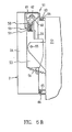
- FIGs. 6B, 7B, 8B and 9B show the movement of the mechanism 51 and the flat type display device 2 with respect to the frame 52.
- arrow head shaped members 63 and 65 engage with the receiving members 64 and 66, respectively, so that the flat type display device 2 is retained in the retracted position at which the keyboard 4 is closed as shown in Figs. 2 and 6A.
- an operator pulls the display device 2 out of the personal computer 1.
- recessed portions 67A and 67B are formed on the right and left side of the display device 2, respectively.
- the operator pulls the recessed portions 67A or 67B by his/her finger.
- the second member 54 which is rigidly coupled to the portions 67A and 67B, is being pulled by the operator, the arrow head shaped member 65 becomes disengaged from the receiving member 66, and the second member 54 is rotated in the clockwise direction.
- the arrow head shaped member 63 becomes disengaged from the receiving member 64, so that the first member 53 starts to rotate in the counter-clockwise direction by the action of the coil spring 56, as shown in Fig. 7B.
- the second member 54 maintains the position shown in the Fig. 7B.
- the second member 53 rotates until a back surface 68 is stopped by the frame 52, as shown in Fig. 8B.
- the flat type display device 2 can be retained at any angled position between these two by the relatively firm engagement between the cam surface 60 and the sliding shoe 58.
- the operator pushes the lower part of the display device 2 to incline the display device 2 to the negative angle position (Fig. 8B) and then pushes the top part of the display device as shown in Fig. 9B, so that first the arrow head shaped member 65 is latched by the receiving member 66 and then the arrow head shaped member 63 is latched by the receiving member 64, whereby the mechanism is returned to the original position as shown in Figs. 5B and 6B.
- the floppy disk drive unit 3 includes a floppy disk load/unload slot 22 and a floppy disk drive device 21.
- a floppy disk 20 can be loaded and unloaded through the slot 22.
- the drive device 21, which includes a read/write head and a step motor, etc., and is shown by the block 21, is well known.
- the longitudinal dimension A, shown in Fig. 1, is larger than the depth B of the personal computer 1, and the depth C of the floppy disk drive unit 3, shown in Fig. 4, is smaller than the depth B.
- the floppy disk drive unit 3 is pivotally mounted at its bottom portion, and can be pivotally moved between its closed or retracted position shown in Fig. 1 and its open or pulled out position shown in Fig. 4. Since the pivot mechanism is well known, it is not shown in the drawings.
- the read/write operations of the floppy disk 20 are performed with the drive unit 3 in either the open position or the closed position since the floppy disk drive device 21 is mounted within the unit 3.
- the depth B of the personal computer 1 is reduced to a minimum value, which is sufficient to provide the stability of the personal computer 1 when it is standing on the desk.
- the slot 22 is hidden within the personal computer 1, whereby the slot 22 is protected against dust or other undesired outside particles.
- FIG. 10 shows the right side components.
- the leg members support the member 11.
- a surface 19 of the leg member 13 is supported by a receiving surface 15.
- the round surfaces 15 and 19 allow the keyboard 4 to pivot between its closed position and its opened position.
- the same mechanism as that shown in the Fig. 10 is provided on the left side of the keyboard with the components being in a mirror relationship with those illustrated in Fig. 10.
- the leg member 13 is detachably mounted on the receiving surface 15, whereby the keyboard 4 can be detached from the personal computer 1, as shown in the Fig. 10.
- the leg member 13 can be pivoted in the clockwise direction from the position shown in the Fig. 10, whereby the detached keyboard 4 can be inclined to face to the operator and supported by the leg member 19.
- FIG. 11 shows the right side latch mechanism 5A.
- the left side latch mechanism 5B is provided with the same structure as that of the mechanism 5A, with the components being in a mirror relationship.
- the latch mechanism 5A includes a slide button 16, a bar 17 coupled to the slide button 16, and an aperture 18. The aperture is formed on the right side wall of the personal computer, as shown in the Fig. 1.
Abstract
Description
- The invention relates to portable electronic apparatus, in particular a personal computer, which is normally stored and used on a desk or similar support.
- Various portable personal computers have been developed. Many of these are the "suit case" type as shown in Fig. 3A of the drawings herein. For carrying this type of personal computer, a handle is provided on the top of the personal computer. In the non-use, storage, condition, the personal computer is placed on a desk in the upright position, as shown in the Fig. 3A. When the personal computer is to be used or operated by an operator, the personal computer is laid down on the desk in a horizontal position, as shown in Fig. 3B, and its cover is opened, as shown in Fig. 3C. A flat type display device is mounted on a back of the cover. By opening the cover, a keyboard appears.
- This type of personal computer has inherent disadvantages. When the personal computer is operated by the operator, it must be laid down, as shown in the Fig. 3B, so that the area contacting the desk is appreciably increased, and the space available on the desk for other purposes is decreased. The operator who frequently uses the personal computer tends to place the personal computer on the desk in the horizontal position, as shown in the Fig. 3B, since he/she finds it a burden to store the personal computer in the upright position, as in Fig. 3A, and then to lay the personal computer down into the horizontal position shown in the Figs. 3B and 3C whenever he/she wants to operate the personal computer.
- Portable personal computers of the type shown in the Figs. 3A-3C are disclosed in US Design Patent No. 243,250 and in US-A-4,497,036. US-A-4,669,053 discloses a personal computer similar to the personal computer shown in the Figs. 3A-3C. As described in this patent specification, a disk drive unit is retractably mounted on the top surface of the personal computer, and a retractable keyboard is pivotally mounted on a front surface, and a display device is fixedly attached in a position substantially parallel to the front surface. The personal computer disclosed has a larger bottom surface than the front surface, whereby it requires a large space on the desk.
- US-A-4,294,496 discloses a portable personal computer wherein a keyboard enclosure is hinged to a main frame enclosure in such a manner that it is possible to fold the keyboard up against the main frame and to latch the two together. A disk drive unit is mounted in such a manner that a surface or plane of a disk in the drive unit is parallel to left and right side surfaces. The personal computer disclosed requires a large space on the desk.
- US-A-4,496,943 discloses a portable information display system which includes a compact enclosure of a size to fit under a typical airline seat. It includes a fixedly mounted cathode ray tube display and a retractable keyboard pivotally mounted on a front surface. It requires a large distance between the front surface and a back surface due to the cathode ray tube display.
- US-A-4,660,111 discloses a lifting mechanism for a floppy disk drive, which differs from the mechanism of the electronic apparatus described herein.
- The object of the present invention is to provide a portable electronic apparatus which requires the minimum space on the desk both when it is operated or used by the operator and when it is not operated or used.
- The present invention relates to portable electronic apparatus comprising a container having a front surface, a back surface, a top surface, and a bottom surface, and adapted to be stored and used while supported on its bottom surface.
- According to the invention the apparatus is characterised in that the area of the bottom surface is less than the area of the front surface, the front surface comprises a pivotably mounted cover, and a keyboard is mounted on the inside of the pivotally mounted cover.
- When the electronic apparatus is to be used, the cover is opened to make the keyboard available to an operator. The space occupied by the apparatus in use is only increased by the size of the keyboard.
- In order that the invention may be more readily understood, an embodiment will now be described with reference to the accompanying drawings in which:
- Fig. 1 is a perspective view of a portable personal computer shown "open" with the keyboard being positioned in the operating position,
- Fig. 2 is a perspective view of the portable personal computer illustrated in Fig. 1 shown "closed" with the keyboard being moved to its closed position,
- Figs. 3A, 3B and 3C are perspective views of a known type of personal computer,
- Fig. 4 is a perspective view of the portable personal computer illustrated in Fig. 1 with the flat type display device and the floppy disk drive unit moved to their pulled out positions,
- Figs. 5A and 5B illustrate the mechanism for supporting and moving the flat type display device,
- Figs, 6A, 6B, 7A, 7B, 8A, 8B, 9A and 9B illustrate the movement of the moving mechanism and the flat type display device,
- Fig. 10 illustrates the coupling of the keyboard to the rest of the personal computer, and
- Fig. 11 illustrates the mechanism for latching the keyboard into the rest of the personal computer.
- Referring to Fig. 1, a portable type
personal computer 1 includes a flattype display device 2, a floppydisk drive unit 3, and akeyboard 4. Thekeyboard 4 is pivotally mounted on a frame of thepersonal computer 1, and pivotable between the opened position as shown in Fig. 1 and a closed position as shown in Fig. 2. That is, thekeyboard 4 acts as a cover of theportable computer 1. Both the flattype display device 2 and the floppydisk drive unit 3 are also moved between the retracted positions as shown in Fig. 1 and the open positions as shown in Fig. 4. A mechanism for controlling the movement of thedisplay device 2 and the floppydisk drive unit 3 is described hereinafter. - Referring to Fig. 2, the case of the portable
personal computer 1 has atop surface 23, abottom surface 24, afront surface 25, aback surface 26, aleft side surface 27 and aright side surface 28. The area of thebottom surface 24 is smaller than the area of each of thefront surface 25 and theback surface 26. Thebottom surface 24 is placed on the desk during both the non-used state and used state of the personal computer. - Referring to Fig. 1, the
keyboard 4 is mounted on the back inside of the cover. The cover constitutes a main part of the front surface. - A hard disk drive unit, a power supply circuit, a microprocessor, and various circuit boards are mounted within the
personal computer 1. For simplifying the drawings and since they do not form essential parts of the invention, these are not shown in the Figs. 1, 2 and 4. - The flat
type display device 2 is a plasma display device or a liquid crystal display device, or the like. - The
keyboard 4 is retained in the retracted or closed position bylatch mechanisms keyboard 4 is electrically connected to thepersonal computer 1 by acable 6, which is stored in agroove 7 of amember 11. - A
power switch 8 is mounted on asurface 9 of the main part of thepersonal computer 1. Theswitch 8 is a "seesaw" type switch. When the left end of the switch (as viewed in Fig. 1) is in a high position, as shown in Fig. 1, the power is turned on. An extended tab 10 is provided on themember 11. When thekeyboard 4 is closed as shown in Fig. 2, the tab 10 pushes down the raised left end of theswitch 8 to turn off theswitch 8 automatically. - A
handle 16 is mounted on thetop surface 23 of thepersonal computer 1. - Referring to Figs. 5A and 5B, a
mechanism 51 for controlling the movement of the flattype display device 2 between the retracted (closed) position and the pulled out (open) position is shown. The mechanism is mounted between aright side wall 2A of the flattype display device 2 and aframe 52 of the main part of thepersonal computer 1. The same mechanism with the components being in a mirror relationship to the components shown in Figs. 5A and 5B is mounted between aleft side wall 2B of thedisplay device 2 and a left side frame. - The
mechanism 51 includes afirst member 53 and asecond member 54. Thefirst member 53 is pivotally mounted on theframe 52 at apivot point 55, and is biased in a counter-clockwise direction (as viewed in the Figures) by acoil spring 56. Aslot 57 is formed in the upper portion of thefirst member 53. A slidingshoe 58 and acoil spring 59 are mounted within theslot 57. The slidingshoe 58 is pressed firmly against acam surface 60 of acam member 61 by thecoil spring 59. Thecam member 61 is rigidly mounted on thesecond member 54. By the firm engagement of the slidingshoe 58 and thecam surface 60, thedisplay device 2 can be moved into and maintained at any angled position relative to the rest of the computer. Thesecond member 54 is pivotally mounted on thefirst member 53 at apivot point 62. A first latch comprising an arrow head shapedmember 63 and a receivingmember 64 and second latch comprising an arrow head shapedmember 65 and a receivingmember 66 are provided to latch the flattype display device 2 to theframe 52 as illustrated in Fig. 5B. - Referring to Figs. 6B, 7B, 8B and 9B, these show the movement of the
mechanism 51 and the flattype display device 2 with respect to theframe 52. - In Fig. 6B, the arrow head shaped
members members type display device 2 is retained in the retracted position at which thekeyboard 4 is closed as shown in Figs. 2 and 6A. - To disengage the first and second latches, an operator pulls the
display device 2 out of thepersonal computer 1. For this purpose, recessedportions display device 2, respectively. The operator pulls the recessedportions second member 54, which is rigidly coupled to theportions member 65 becomes disengaged from the receivingmember 66, and thesecond member 54 is rotated in the clockwise direction. The arrow head shapedmember 63 becomes disengaged from the receivingmember 64, so that thefirst member 53 starts to rotate in the counter-clockwise direction by the action of thecoil spring 56, as shown in Fig. 7B. As the operator continues to pull the recessedportion 67A, thesecond member 54 maintains the position shown in the Fig. 7B. Thesecond member 53 rotates until aback surface 68 is stopped by theframe 52, as shown in Fig. 8B. - It is apparent that, when the flat
type display device 2 is retained in the retracted position, as shown in Figs. 1, 5B, 6A and 6B, the distance between thepivot point 62 and theframe surface 69 is a minimum X₁, as shown in Fig. 6B, and when thedisplay device 2 is pulled out, the distance between thepivot point 62 and theframe surface 69 is a maximum X₂, as shown in Fig. 8B. As the flattype display device 2 is moved from its retracted position to its pulled out position, it is pivoted at thepivot point 62 between a positive angle position, such as a position shown by thesecond member 54 in Fig. 8B and a negative angle position, such as a position shown by the dashedline 54′ corresponding to the position of the second member in Fig. 8B. The flattype display device 2 can be retained at any angled position between these two by the relatively firm engagement between thecam surface 60 and the slidingshoe 58. - To return the flat
type display device 2 to its retracted position, the operator pushes the lower part of thedisplay device 2 to incline thedisplay device 2 to the negative angle position (Fig. 8B) and then pushes the top part of the display device as shown in Fig. 9B, so that first the arrow head shapedmember 65 is latched by the receivingmember 66 and then the arrow head shapedmember 63 is latched by the receivingmember 64, whereby the mechanism is returned to the original position as shown in Figs. 5B and 6B. - Describing the floppy
disk drive unit 3 with reference to Figs. 1 and 4, the floppydisk drive unit 3 includes a floppy disk load/unloadslot 22 and a floppydisk drive device 21. Afloppy disk 20 can be loaded and unloaded through theslot 22. Thedrive device 21, which includes a read/write head and a step motor, etc., and is shown by theblock 21, is well known. The longitudinal dimension A, shown in Fig. 1, is larger than the depth B of thepersonal computer 1, and the depth C of the floppydisk drive unit 3, shown in Fig. 4, is smaller than the depth B. The floppydisk drive unit 3 is pivotally mounted at its bottom portion, and can be pivotally moved between its closed or retracted position shown in Fig. 1 and its open or pulled out position shown in Fig. 4. Since the pivot mechanism is well known, it is not shown in the drawings. - The read/write operations of the
floppy disk 20 are performed with thedrive unit 3 in either the open position or the closed position since the floppydisk drive device 21 is mounted within theunit 3. By arranging the surface of thefloppy disk 20 parallel to a surface of the flattype display device 2, the depth B of thepersonal computer 1 is reduced to a minimum value, which is sufficient to provide the stability of thepersonal computer 1 when it is standing on the desk. In the closed or retracted position, theslot 22 is hidden within thepersonal computer 1, whereby theslot 22 is protected against dust or other undesired outside particles. - With reference to Figs. 1 and 10, the mechanism for pivoting the
keyboard 4 to allow for its movement between its closed position as shown in Fig. 2 and its open position as shown in Figs. 1 and 4 is described.Leg members 13 are pivotally mounted at pivot points 14 on both the right and left sides of thekeyboard 4. Fig. 10 shows the right side components. The leg members support themember 11. Asurface 19 of theleg member 13 is supported by a receivingsurface 15. The round surfaces 15 and 19 allow thekeyboard 4 to pivot between its closed position and its opened position. The same mechanism as that shown in the Fig. 10 is provided on the left side of the keyboard with the components being in a mirror relationship with those illustrated in Fig. 10. Theleg member 13 is detachably mounted on the receivingsurface 15, whereby thekeyboard 4 can be detached from thepersonal computer 1, as shown in the Fig. 10. Theleg member 13 can be pivoted in the clockwise direction from the position shown in the Fig. 10, whereby thedetached keyboard 4 can be inclined to face to the operator and supported by theleg member 19. - With reference to Figs. 1, 2 and 11, these illustrate the
latch mechanisms keyboard 4 in the closed position. Fig. 11 shows the rightside latch mechanism 5A. The leftside latch mechanism 5B is provided with the same structure as that of themechanism 5A, with the components being in a mirror relationship. Thelatch mechanism 5A includes aslide button 16, abar 17 coupled to theslide button 16, and anaperture 18. The aperture is formed on the right side wall of the personal computer, as shown in the Fig. 1. - Rightward movement of the
slide button 16 by the operator causes thebar 17 to enter into theaperture 18, whereby thekeyboard 4 is locked in the closed position. Leftward movement of theslide button 16 by the operator causes thebar 17 to retract from theaperture 18, thereby the back of thelatch mechanism 5A is released.
Claims (8)
a container (1) having a front surface (25), a back surface (26), a top surface (23), and a bottom surface (24), and adapted to be stored and used while supported on its bottom surface (24),
characterised in that
the area of said bottom surface (24) is less than the area of said front surface (25),
said front surface (25) comprises a pivotably mounted cover, and
a keyboard (4) is mounted on the inside of said pivotally mounted cover.
a first member (53) pivotally mounted on a frame of said container at a first pivot point (55),
a second member (54) pivotally mounted on said first member at second pivot point (62) which is spaced from said first pivot point, and supporting said flat type display device (2).
Applications Claiming Priority (2)
| Application Number | Priority Date | Filing Date | Title |
|---|---|---|---|
| JP63300808A JPH02148114A (en) | 1988-11-30 | 1988-11-30 | Personal computer |
| JP300808/88 | 1988-11-30 |
Publications (3)
| Publication Number | Publication Date |
|---|---|
| EP0371642A2 true EP0371642A2 (en) | 1990-06-06 |
| EP0371642A3 EP0371642A3 (en) | 1991-01-16 |
| EP0371642B1 EP0371642B1 (en) | 1996-02-28 |
Family
ID=17889351
Family Applications (1)
| Application Number | Title | Priority Date | Filing Date |
|---|---|---|---|
| EP89311633A Expired - Lifetime EP0371642B1 (en) | 1988-11-30 | 1989-11-10 | Portable electronic apparatus |
Country Status (9)
| Country | Link |
|---|---|
| US (1) | US5021922A (en) |
| EP (1) | EP0371642B1 (en) |
| JP (1) | JPH02148114A (en) |
| KR (1) | KR920005601B1 (en) |
| CN (1) | CN1012922B (en) |
| DE (1) | DE68925785T2 (en) |
| HK (1) | HK203996A (en) |
| MY (1) | MY108542A (en) |
| SG (1) | SG44421A1 (en) |
Cited By (7)
| Publication number | Priority date | Publication date | Assignee | Title |
|---|---|---|---|---|
| DE4032959A1 (en) * | 1990-10-17 | 1992-04-23 | Josef Schreiner | Portable computer integrated into case - incorporates pivoting module unit in lid leaving room in case for portable office printer, modem connector |
| US5187644A (en) * | 1991-11-14 | 1993-02-16 | Compaq Computer Corporation | Compact portable computer having an expandable full size keyboard with extendable supports |
| EP0627291A1 (en) * | 1993-05-12 | 1994-12-07 | DR. BOY GmbH | Control unit for an injection moulding machine |
| EP0659010A1 (en) * | 1993-12-15 | 1995-06-21 | Canon Kabushiki Kaisha | Electronic apparatus having display device |
| WO2001071670A1 (en) * | 2000-03-22 | 2001-09-27 | Italdata Ingegneria Dell'idea S.P.A. | Portable apparatus for scientific identification of an individual |
| WO2002025942A1 (en) * | 2000-09-25 | 2002-03-28 | Pixeltronic Ag | Television receiver having a flat display |
| DE102023125102A1 (en) | 2022-09-26 | 2024-03-28 | Engel Austria Gmbh | Control unit for a shaping machine |
Families Citing this family (51)
| Publication number | Priority date | Publication date | Assignee | Title |
|---|---|---|---|---|
| JP2766347B2 (en) * | 1989-10-31 | 1998-06-18 | 株式会社東芝 | Small electronic equipment |
| JP2547102B2 (en) * | 1989-12-15 | 1996-10-23 | クラリオン株式会社 | Liquid crystal display device with slide storage |
| JP2910114B2 (en) * | 1990-01-20 | 1999-06-23 | ソニー株式会社 | Electronics |
| US5157585A (en) * | 1991-06-27 | 1992-10-20 | Compaq Computer Corporation | Compact AC-powerable portable computer having a CPU and expansion bay in an upper housing pivotally attached to a lower housing |
| US5260884A (en) * | 1991-07-17 | 1993-11-09 | Jonathan Stern | Brief case having integral computer |
| DE4203503A1 (en) * | 1992-02-07 | 1993-08-12 | Ezu Metallwaren Eberha | Carrying case for portable computer - forms compact assembly for housing computer and accessories which extends to provide stable in-car work station |
| US5247285A (en) * | 1992-03-06 | 1993-09-21 | Everex Systems, Inc. | Standup portable personal computer with detachable wireless keyboard and adjustable display |
| WO1994000037A1 (en) * | 1992-06-24 | 1994-01-06 | Cad Forms Technology Inc. | A pen based computer protective case |
| US5847685A (en) * | 1992-08-19 | 1998-12-08 | Alpine Electronics, Inc. | Vehicle-mounted display mechanism |
| US5796575A (en) * | 1992-12-21 | 1998-08-18 | Hewlett-Packard Company | Portable computer with hinged cover having a window |
| DE4400853A1 (en) * | 1994-01-14 | 1995-07-20 | Hans Matuschek | Transportable computer with briefcase type housing |
| KR0130883Y1 (en) * | 1994-02-02 | 1998-12-15 | 김광호 | Hard disk drive attaching/detaching apparatus for computer |
| DE4408295C2 (en) * | 1994-03-11 | 1996-12-05 | G S A Elektro Elektronik Baute | Device for the functional combination of electrical and / or electronic devices |
| DE19511309C2 (en) * | 1994-04-19 | 2001-09-13 | Loh Kg Ritto Werk | Housing with a display device |
| US5580107A (en) * | 1995-09-25 | 1996-12-03 | Dell U.S.A., L.P. | Hidden latch hook for portable personal computer and the like |
| US5748442A (en) * | 1995-11-08 | 1998-05-05 | Palo Alto Design Group | Personal computer and chassis having interchangeable trim plates for horizontal model and tower model configuration, one trim plate having a larger periphery for use as a base plate |
| US6151012A (en) * | 1995-11-16 | 2000-11-21 | Bullister; Edward | Multifunctional portable computing device with special housing |
| US6697055B1 (en) | 1995-11-16 | 2004-02-24 | Edward Bullister | Multifunctional portable computing device with special housing |
| US5654846A (en) * | 1995-12-28 | 1997-08-05 | Sony Corporation | Disk drive unit tilt device |
| US5717431A (en) * | 1996-01-05 | 1998-02-10 | Dell Usa, L.P. | Ergonomic keyboard for a portable computer and methods of operation and manufacture therefor |
| US6246449B1 (en) | 1996-08-16 | 2001-06-12 | Rosen Products Llc | Display unit |
| US5946055A (en) * | 1996-08-16 | 1999-08-31 | Rosen Product Development, Inc. | Display unit |
| US5712761A (en) * | 1996-09-23 | 1998-01-27 | International Business Machines, Corporation | Computer system having cooperating spring, gear tracks and geared dampers for allowing a drive housing to move between open and closed positions |
| US5764480A (en) * | 1996-09-23 | 1998-06-09 | International Business Machines Corporation | Computer system having a latching drive housing which pivots on hinge pins between an open position wherein a DASD is accessible and a closed position wherein the DASD is not accessible |
| US5878271A (en) * | 1996-09-23 | 1999-03-02 | International Business Machines Corporation | Multi-conductor cable architecture and interface for a split system personal computer |
| US5764479A (en) * | 1996-09-23 | 1998-06-09 | International Business Machines Corporation | Split system personal computer having floppy disk drive moveable between accessible and inaccessible positions |
| JPH10222244A (en) * | 1997-02-07 | 1998-08-21 | Hitachi Ltd | Desk-top computer |
| US6168250B1 (en) | 1998-07-10 | 2001-01-02 | Zmicrosystems | Flat panel monitor mounting assembly |
| US6017106A (en) * | 1999-02-02 | 2000-01-25 | Gateway 2000, Inc | Removable carry handle and adapter for portable computer |
| US6292236B1 (en) | 1999-03-26 | 2001-09-18 | Rosen Products Llc | Automotive-ceiling-mounted monitor |
| USD446507S1 (en) | 1999-06-18 | 2001-08-14 | Rosen Products Llc | Ceiling-mounted monitor |
| US6654235B2 (en) * | 2000-01-25 | 2003-11-25 | Bruce Imsand | Portable workstation computer |
| US7679578B2 (en) * | 2003-05-15 | 2010-03-16 | Audiovox Corporation | Headrest mountable video system |
| JP3487822B2 (en) * | 2000-11-27 | 2004-01-19 | Necパーソナルプロダクツ株式会社 | Apparatus for protecting a moving part of electronic equipment and method of protecting the same |
| US6680843B2 (en) | 2001-09-28 | 2004-01-20 | International Business Machines Corporation | All-in-one personal computer with tool-less quick-release features for various elements thereof including a reusable thin film transistor monitor |
| TW518562B (en) * | 2001-09-28 | 2003-01-21 | Wistron Corp | Optical disk driver module having conjoint switch |
| EP1365310A1 (en) * | 2002-05-22 | 2003-11-26 | Tektronix Berlin GmbH & Co. KG | System comprising a keyboardholder and a keyboard |
| DE10234715B8 (en) * | 2002-07-30 | 2008-04-03 | Röchling Automotive AG & Co. KG | Rotatable body with unlocking element |
| TWI234522B (en) * | 2003-01-24 | 2005-06-21 | Primax Electronics Ltd | Pivoting device operated with auxiliary force and multi-task machine including the same |
| JP4667725B2 (en) * | 2003-04-25 | 2011-04-13 | パナソニック株式会社 | Portable information processing device |
| US7909397B2 (en) * | 2003-05-15 | 2011-03-22 | Audiovox Corporation | In-vehicle docking station for a portable media player |
| US7609946B2 (en) | 2003-05-15 | 2009-10-27 | Audiovox Corporation | Portable video system |
| US7954894B2 (en) * | 2003-05-15 | 2011-06-07 | Audiovox Corporation | Headrest mountable video system |
| US7791586B2 (en) * | 2003-05-15 | 2010-09-07 | Audiovox Corporation | Entertainment system mountable in a vehicle seat |
| JP2006147008A (en) * | 2004-11-17 | 2006-06-08 | Toshiba Corp | Disk drive device and display device with the same |
| ES2451645T3 (en) | 2005-11-07 | 2014-03-28 | Audiovox Corporation | Audio-visual system that can be mounted on a vehicle seat and its assembly and visualization procedures |
| TWI309360B (en) * | 2006-06-16 | 2009-05-01 | Asustek Comp Inc | Otg type storage device and notebook computer using the same |
| TW200900898A (en) * | 2007-06-21 | 2009-01-01 | Compal Electronics Inc | Latching mechanism and base casing of notebook using the same |
| US8662605B2 (en) * | 2011-02-18 | 2014-03-04 | Rubbermaid Incorporated | Mobile technology cabinet |
| CN103064462A (en) * | 2011-10-19 | 2013-04-24 | 苏州辛瑞拉光电科技有限公司 | Hand-held box type computer |
| US8687362B2 (en) * | 2012-05-02 | 2014-04-01 | Yifan Zhao | Portable briefcase office |
Citations (3)
| Publication number | Priority date | Publication date | Assignee | Title |
|---|---|---|---|---|
| WO1986006516A1 (en) * | 1985-04-26 | 1986-11-06 | Ncr Corporation | Portable personal computing system |
| US4718740A (en) * | 1986-10-28 | 1988-01-12 | Allied Corporation | Housing and stowage mechanism for terminal keyboard and display panel |
| GB2200783A (en) * | 1987-01-15 | 1988-08-10 | Compaq Computer Corp | Adjustable display panel for portable computer |
Family Cites Families (8)
| Publication number | Priority date | Publication date | Assignee | Title |
|---|---|---|---|---|
| JPS5312119U (en) * | 1976-07-14 | 1978-02-01 | ||
| JPS55102028A (en) * | 1979-01-31 | 1980-08-04 | Toshiba Corp | Terminal unit |
| JPS6095782A (en) * | 1983-10-29 | 1985-05-29 | Nippon Telegr & Teleph Corp <Ntt> | Signal transmission device of memory card write and read device |
| US4862353A (en) * | 1984-03-05 | 1989-08-29 | Tektronix, Inc. | Modular input device system |
| JPS60189523A (en) * | 1984-03-09 | 1985-09-27 | Matsushita Electric Ind Co Ltd | Information processor |
| US4704604A (en) * | 1984-11-28 | 1987-11-03 | Zenith Electronics Corporation | Pivoting mount for detachable keyboard |
| JPS61160525U (en) * | 1985-03-25 | 1986-10-04 | ||
| JPS63110929U (en) * | 1987-01-06 | 1988-07-16 |
-
1988
- 1988-11-30 JP JP63300808A patent/JPH02148114A/en active Granted
-
1989
- 1989-10-27 MY MYPI89001493A patent/MY108542A/en unknown
- 1989-10-28 CN CN89108195A patent/CN1012922B/en not_active Expired
- 1989-10-30 KR KR1019890015631A patent/KR920005601B1/en not_active IP Right Cessation
- 1989-11-10 EP EP89311633A patent/EP0371642B1/en not_active Expired - Lifetime
- 1989-11-10 SG SG1996000275A patent/SG44421A1/en unknown
- 1989-11-10 DE DE68925785T patent/DE68925785T2/en not_active Expired - Fee Related
- 1989-11-22 US US07/441,030 patent/US5021922A/en not_active Expired - Fee Related
-
1996
- 1996-11-07 HK HK203996A patent/HK203996A/en not_active IP Right Cessation
Patent Citations (3)
| Publication number | Priority date | Publication date | Assignee | Title |
|---|---|---|---|---|
| WO1986006516A1 (en) * | 1985-04-26 | 1986-11-06 | Ncr Corporation | Portable personal computing system |
| US4718740A (en) * | 1986-10-28 | 1988-01-12 | Allied Corporation | Housing and stowage mechanism for terminal keyboard and display panel |
| GB2200783A (en) * | 1987-01-15 | 1988-08-10 | Compaq Computer Corp | Adjustable display panel for portable computer |
Cited By (10)
| Publication number | Priority date | Publication date | Assignee | Title |
|---|---|---|---|---|
| DE4032959A1 (en) * | 1990-10-17 | 1992-04-23 | Josef Schreiner | Portable computer integrated into case - incorporates pivoting module unit in lid leaving room in case for portable office printer, modem connector |
| US5187644A (en) * | 1991-11-14 | 1993-02-16 | Compaq Computer Corporation | Compact portable computer having an expandable full size keyboard with extendable supports |
| EP0627291A1 (en) * | 1993-05-12 | 1994-12-07 | DR. BOY GmbH | Control unit for an injection moulding machine |
| EP0659010A1 (en) * | 1993-12-15 | 1995-06-21 | Canon Kabushiki Kaisha | Electronic apparatus having display device |
| US5719645A (en) * | 1993-12-15 | 1998-02-17 | Canon Kabushiki Kaisha | Electronic apparatus having display device |
| WO2001071670A1 (en) * | 2000-03-22 | 2001-09-27 | Italdata Ingegneria Dell'idea S.P.A. | Portable apparatus for scientific identification of an individual |
| US6938823B2 (en) | 2000-03-22 | 2005-09-06 | Italdata Ingegneria Dell'idea S.P.A. | Portable apparatus for scientific identification of an individual |
| CZ301456B6 (en) * | 2000-03-22 | 2010-03-10 | Italdata Ingegneria Dell'idea S. P. A. | Portable apparatus for exact identification of a person |
| WO2002025942A1 (en) * | 2000-09-25 | 2002-03-28 | Pixeltronic Ag | Television receiver having a flat display |
| DE102023125102A1 (en) | 2022-09-26 | 2024-03-28 | Engel Austria Gmbh | Control unit for a shaping machine |
Also Published As
| Publication number | Publication date |
|---|---|
| HK203996A (en) | 1996-11-15 |
| CN1043212A (en) | 1990-06-20 |
| MY108542A (en) | 1996-10-31 |
| JPH02148114A (en) | 1990-06-07 |
| KR920005601B1 (en) | 1992-07-09 |
| SG44421A1 (en) | 1997-12-19 |
| EP0371642B1 (en) | 1996-02-28 |
| CN1012922B (en) | 1991-06-19 |
| KR900008368A (en) | 1990-06-04 |
| DE68925785D1 (en) | 1996-04-04 |
| JPH0574088B2 (en) | 1993-10-15 |
| US5021922A (en) | 1991-06-04 |
| DE68925785T2 (en) | 1996-09-26 |
| EP0371642A3 (en) | 1991-01-16 |
Similar Documents
| Publication | Publication Date | Title |
|---|---|---|
| EP0371642B1 (en) | Portable electronic apparatus | |
| US7298610B2 (en) | Supporting apparatus for portable computer | |
| US5107401A (en) | Lap top computer with tilting mechanism consisting of a battery pack pivotally attached on a rear surface | |
| US5539615A (en) | Notebook computer keyboard with slot-supported sliding pin tilt mechanism | |
| US5175671A (en) | Expanding apparatus for portable electronic apparatus | |
| US5629832A (en) | Electronic device keyboard with pivot bar tilt mechanism | |
| US7111852B2 (en) | Utility cart | |
| US5341154A (en) | Portable personal computer | |
| US6168250B1 (en) | Flat panel monitor mounting assembly | |
| US4903221A (en) | Keyboard latching arrangement for portable computers | |
| US4901261A (en) | Retractable handle and latch for portable computers | |
| US7097355B2 (en) | X-ray equipment with cassette storage box locking means | |
| US7095607B2 (en) | Electronic apparatus with a removable component | |
| JPH0895669A (en) | Electronic equipment system | |
| JP2001069391A (en) | Enlargement unit, portable information processor and image pickup device | |
| JP2001100912A (en) | Pointing device | |
| JP2986082B2 (en) | Portable information processing equipment | |
| US5239444A (en) | Tiltable portable electronic apparatus with sliding tilt leg | |
| GB2266360A (en) | Electronic apparatus with a keyboard and a trackball. | |
| JPH0772954A (en) | Tilt mechanism for portable computer | |
| JP2629032B2 (en) | Electronics | |
| JP2923389B2 (en) | Handheld computer device capable of handwriting input | |
| JP2598497B2 (en) | Tripod built-in grip | |
| JPH10293625A (en) | Desktop housing case for notebook-sized personal computer | |
| JPH09244763A (en) | Electronic equipment |
Legal Events
| Date | Code | Title | Description |
|---|---|---|---|
| PUAI | Public reference made under article 153(3) epc to a published international application that has entered the european phase |
Free format text: ORIGINAL CODE: 0009012 |
|
| AK | Designated contracting states |
Kind code of ref document: A2 Designated state(s): DE FR GB |
|
| 17P | Request for examination filed |
Effective date: 19900926 |
|
| PUAL | Search report despatched |
Free format text: ORIGINAL CODE: 0009013 |
|
| AK | Designated contracting states |
Kind code of ref document: A3 Designated state(s): DE FR GB |
|
| 17Q | First examination report despatched |
Effective date: 19931126 |
|
| GRAA | (expected) grant |
Free format text: ORIGINAL CODE: 0009210 |
|
| AK | Designated contracting states |
Kind code of ref document: B1 Designated state(s): DE FR GB |
|
| REF | Corresponds to: |
Ref document number: 68925785 Country of ref document: DE Date of ref document: 19960404 |
|
| ET | Fr: translation filed | ||
| PGFP | Annual fee paid to national office [announced via postgrant information from national office to epo] |
Ref country code: FR Payment date: 19961112 Year of fee payment: 8 |
|
| PGFP | Annual fee paid to national office [announced via postgrant information from national office to epo] |
Ref country code: DE Payment date: 19961127 Year of fee payment: 8 |
|
| PLBE | No opposition filed within time limit |
Free format text: ORIGINAL CODE: 0009261 |
|
| STAA | Information on the status of an ep patent application or granted ep patent |
Free format text: STATUS: NO OPPOSITION FILED WITHIN TIME LIMIT |
|
| 26N | No opposition filed | ||
| PG25 | Lapsed in a contracting state [announced via postgrant information from national office to epo] |
Ref country code: FR Free format text: THE PATENT HAS BEEN ANNULLED BY A DECISION OF A NATIONAL AUTHORITY Effective date: 19971130 |
|
| PG25 | Lapsed in a contracting state [announced via postgrant information from national office to epo] |
Ref country code: DE Free format text: LAPSE BECAUSE OF NON-PAYMENT OF DUE FEES Effective date: 19980801 |
|
| REG | Reference to a national code |
Ref country code: FR Ref legal event code: ST |
|
| REG | Reference to a national code |
Ref country code: GB Ref legal event code: IF02 |
|
| PGFP | Annual fee paid to national office [announced via postgrant information from national office to epo] |
Ref country code: GB Payment date: 20041101 Year of fee payment: 16 |
|
| PG25 | Lapsed in a contracting state [announced via postgrant information from national office to epo] |
Ref country code: GB Free format text: LAPSE BECAUSE OF NON-PAYMENT OF DUE FEES Effective date: 20051110 |
|
| GBPC | Gb: european patent ceased through non-payment of renewal fee |
Effective date: 20051110 |