EP0369719A2 - Image processing apparatus - Google Patents
Image processing apparatus Download PDFInfo
- Publication number
- EP0369719A2 EP0369719A2 EP89311742A EP89311742A EP0369719A2 EP 0369719 A2 EP0369719 A2 EP 0369719A2 EP 89311742 A EP89311742 A EP 89311742A EP 89311742 A EP89311742 A EP 89311742A EP 0369719 A2 EP0369719 A2 EP 0369719A2
- Authority
- EP
- European Patent Office
- Prior art keywords
- image data
- inputting
- image
- data
- input
- Prior art date
- Legal status (The legal status is an assumption and is not a legal conclusion. Google has not performed a legal analysis and makes no representation as to the accuracy of the status listed.)
- Granted
Links
Images


Classifications
-
- G—PHYSICS
- G06—COMPUTING; CALCULATING OR COUNTING
- G06T—IMAGE DATA PROCESSING OR GENERATION, IN GENERAL
- G06T11/00—2D [Two Dimensional] image generation
- G06T11/001—Texturing; Colouring; Generation of texture or colour
Definitions
- the present invention relates to an image processing apparatus for concentration modulating input image data.
- a texture process for concentration modulating image data by using arbitrary pattern data
- a texture process denotes that an input image as shown in Fig. 7A is concentration modulated by using pattern data as shown in Fig. 7B, so that an output image as shown in Fig. 7C is obtained.
- the texture pattern of Fig. 7B is a pattern of a cloth design
- the cloth pattern can be synthesized to the area in the L-shaped character of Fig. 7A.
- an image processing apparatus for outputting an image from an image input in a real-time manner
- the apparatus which can execute such a texture process does not exist.
- the texture process in the case of variably magnifying a texture pattern and executing the concentration modulation to the input image data, after the variably magnifying process was executed to the texture pattern every process, the texture process must be performed, so that it is troublesome.
- an apparatus of a construction as shown in Fig. 1 is considered as a method of realizing that the texture process is executed to an input image in a real-time manner. That is, according to the method, a pattern image for the texture process is previously read and stored, and when an original image which is subjected to the texture process is read, the stored pattern image is read out and calculated by an image modulator and the concentration is modulated.
- Fig. 16A shows a finite size pattern.
- Fig. 16B shows concentration difference lines which are generated when the texture process of the repetitive pattern was executed to an area larger than the size of the finite size pattern of Fig. 16A.
- the present invention is made in consideration of the above conventional technique and it is the first object of the invention to provide an image processing apparatus which can execute the texture process in a real-time manner.
- an invention in which by providing means for producing at least one area signal, particularly, a non-rectangular area signal, a texture process is executed to at least one area and the result can be output in a real-time manner.
- the second object of the invention is to provide an image processing apparatus which can execute a variety of texture processes.
- an invention in which by providing means for storing a modulation pattern and means for controlling addresses of a memory to store the modulation pattern, variably magnifying processes which are different in the horizontal and vertical directions are executed independently of image data to be modulated, texture processes are executed, and the result can be output in a real-time manner.
- the third object of the invention is to provide an image processing apparatus which can prevent a deterioration in picture quality when a texture process is executed.
- the third invention of the patent application comprises: input means for inputting first image data; memory means for storing the first image data; means for executing a proper process to the first image data; input means for inputting second image data; and means for modulating a concentration of the second image data by an output from the means for executing the proper process.
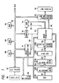
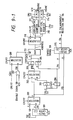
- Fig. 1 is a block diagram including a texture process of a color copying apparatus as an image processing apparatus of the embodiment.
- the apparatus of the embodiment comprises: a CPU 108 for processing and calculating which is connected to a CPU bus 117; an ROM 109 in which programs for the texture process and the like are previously stored; an RAM 110 for auxiliary storage which is used as a work area; a CCD 100 to read image data; an A/D conversion unit 101 for converting an analog signal into a digital signal; a color masking unit 102; an undercolor removing unit or undercolor removal unit (hereinafter, simply referred to as an UCR unit) 103 for removing the undercolor from output data 123 of the color masking unit 102; a gradation correction unit 104 to execute the gamma conversion to image data 124; an operation unit 105 to execute various inputs; an image modulator 114 to execute the texture process on the basis of image data 120 and data of an RAM 113; an area generation circuit 111 to generate an area signal (particularly
- a color laser beam printer is used as a printer unit 106 in the example.
- the printer unit 106 sequentially develops the colors of Y (yellow), M (magenta), C (cyan), and K (black) and obtains a full-color image output.
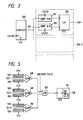
- Fig. 3 is an explanatory diagram of the area generation circuit 111.
- the area designation circuit 111 comprises: a counter 300 which is counted up by the input of an image clock VCK and is reset by the input of a horizontal sync signal HSYNC and outputs a count signal 304; comparators 301 and 302 to indicate an active start point and an active end point of the area signal on the basis of data which is input from the digitizer 106; and a JK flip-flop (JK F/F) 303 which executes the toggling operation on the basis of outputs of the two comparators 301 and 302 and generates an area signal, that is, an enable signal 128-1 of the texture process.
- JK F/F JK flip-flop
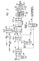
- Fig. 2 is a diagram for explaining a texture processing circuit as a characteristic section of the invention. Explanation will now be made individually hereinbelow with respect to a writing unit to write modulation data (texture pattern) 218 into the RAM 113 and a calculating unit (texture processing unit) of data 216 from the RAM 113 and image data 215 which is subjected to the texture process.
- a writing unit to write modulation data (texture pattern) 218 into the RAM 113 and a calculating unit (texture processing unit) of data 216 from the RAM 113 and image data 215 which is subjected to the texture process.
- a calculator (1) 201 comprises: luminance to concentration converters for receiving input signals of R (red), G (green), and B (blue) and outputting signals of Y (yellow), M (magenta), and C (cyan); and a YMC mean value circuit.
- RGB input signals 122 (Y + M + C)/3, that is concentration data 219 of eight bits is obtained.
- the concentration data 219 is input to the B side of a selector 200.
- data of eight bits is input to the A side of the selector 200 through the CPU bus 117.
- This 8-bit data is the video data and is the read image data which is not transmitted through the calculator (1) 201.
- the selector 200 selects the concentration data on the B side in response to an instruction of the CPU 108.
- a selector 202 selects the A side.
- an OR circuit 207 calculates the OR of the enable signal 128 and the VCK.
- a selector 208 selects the B side by an instruction of the CPU 108.
- a signal 220 is input as an enable signal to a WE input terminal of the memory 113 and to a driver 203.
- a memory address signal is produced by a vertical counter 212 which is counted up synchronously with the horizontal sync signal HSYNC and a horizontal counter 211 which is counted up synchronously with the image clock VCK.
- a selector 210 selects the B side and the selected memory address signal is input to an address in the memory 113.
- the concentration pattern of the input image is written into the memory 113.
- the position of an original is designated by the digitizer 106 and the CCD 100 then the pattern of the designated position is written into the memory 113.
- the selector 202 selects the B side to input the CPU data.
- the selector 208 selects the WE signal of the CPU on the A side.
- the WE signal is input as WE of the memory 113 and an enable signal of the driver 203.
- the CPU address signal on the A side is selected by the selector 210 and is input to an address in the memory 113. In this manner, by switching the addresses in the case where the pattern data from the reader is stored into the memory 113 and the case where the pattern data from the CPU 108 is stored, the pattern data even from any input can be stored.
- an arbitrary concentration pattern is written into the memory 113. (Calculating unit of data 216 of the RAM 113 and image data 215)
- the above calculation is realized by a calculator (2) 215.
- the calculator (2) comprises a multiplier.
- the calculation of the data 216 and 215 is executed in only the portion where the enable signal 128 generated by the area generation circuit 111 is active, so that the texture process is executed.
- the enable signal 218 is disenable, the data 215 is set to the through state, so that the image data 126 of eight bits which is not subjected to the texture process is output.
- the calculation to synthesize the data (texture pattern data) 216 of the RAM 113 and the image data 215 is realized by the calculator (2) 215.
- the calculator (2) comprises a multiplier.
- the calculation of the data 216 of the calculator and the data 215 is executed in only the portion where the enable signal 218 to control whether the texture process is executed or not is active. When the signal 218 is disenable, the data 215 is set to the through state.
- the input image data 215 is the data 120 on the A side which is selected by the selector 200, that is, the video data.
- Another input data 216 is the texture pattern data which is output from the memory 113.
- the address control is executed by using the horizontal counter 211 and vertical counter 212 on the B side of the selector 210.
- the CPU address on the A side of the selector 210 is used.
- the reducing process is executed when image data 217 is written into the memory 113.
- Data are set into two r.m.p. (rate multipliers) 213 and 214 by the CPU 108 so that the image clocks VCK are thinned out by the r.m.p. 213 and the horizontal sync signals HSYNC are thinned out by the r.m.p. 214. Due to this, the counting-up speeds of the horizontal counter 211 and vertical counter 212 become slow, so that the reduced data is written into the memory 113.
- the calculation of the data 216 of the RAM 113 and the image data 215 is executed (when the texture process is performed)
- data are set into the r.m.p. 213 and 214 from the CPU 108 so that the VCK and HSYNC are not thinned out, respectively.
- a fineness of the repetitive pattern can be arbitrarily determined by the above enlarging and reducing processes.
- the fundamental construction is similar to Fig. 1. Only a different point relates to a construction of the area generation circuit 111.
- the area generation circuit 111 comprises the circuits shown in Figs. 3 and 5.
- the area generation circuit 111 outputs a "1" signal from an AND gate 507 when the area signal generated from the circuit of Fig. 3 is set to 1 and when color separation data R (122-1), G (122-2), and B (122-3) of the input image data lie within a predetermined luminance range which has been preset by the CPU 108.
- Reference numeral 511 denotes a timing circuit which is provided to synchronize the enable signal 128.
- the non-rectangular texture process can be executed without using a memory to designate an area although it is difficult to adjust the timing.
- the texture process can be easily executed to at least one area, particularly, a non-rectangular area in a real-time manner.
- the apparatus can be widely applied to the design field.
- the modulation pattern can be variably magnified independently of the image data to be modulated, the image data can be easily modulated by the variably magnified modulation pattern in a real-time manner. There is an advantage such that the apparatus can be widely applied to the design field.
- the discontinuity at the joint surfaces of the images in the right/left and upper/lower positions is weakened, thereby enabling the image process to be more continuously executed.
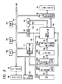
- Fig. 8 is a block diagram including the texture process in the image processing apparatus of the embodiment of the invention.
- a fundamental construction of the image processing apparatus in the embodiment is also similar to that in Fig. 1. Therefore, the description of each section is omitted.
- Fig. 9-1 is a diagram for explaining a texture processing circuit. Since a construction of Fig. 9-1 is also similar to Fig. 2, its description is omitted.
- the image processing apparatus using the invention includes the operation unit (105 in Fig. 8) having: means (key input means) for selecting the texture mode; and means (key input means) for making the effect of the filtering process of the invention operative or inoperative in the texture process.
- Each means can set, check, and change.
- Fig. 10-1 is a flowchart showing an outline of the operation of the apparatus.
- an operation command is input from the operation unit 105 (step S-400).
- a check is made to see if the operation command is a copy start command or not. If it is not the copy start command, a check is made to see if the operation command is a texture pattern reading command or not (S-402). If the operation command is the texture pattern reading command (S-403), an original is scanned and the image data obtained is stored into the texture pattern RAM 113 (S-408). On the other hand, if the operating command is not the reading command, a check is made to see if the operating command indicates to execute other process or not (S-405). If YES, the other process is executed (S-407).
- the apparatus When the reading operation is finished, if the execution of the filtering process is not set (S-410), the apparatus again waits for the input of the operation command (S-400). If the execution of the filtering process has been set (S-409), the filtering process as will be explained hereinlater is performed.
- a general filter of an average in a block as shown in Fig. 12-2 is used as a smoothing filter.
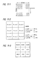
- a size of RAM 113 for the texture pattern is set to 512 dots x 512 dots as shown in Fig. 11-1.
- Fig. 11-2 shows a matrix of 3 x 3 indicative of the addresses in the memory.
- Fig. 11-3 shows a practical example.
- the operation which is executed in the circuit of Fig. 9-1 will be described with reference to a flowchart for the CPU 108 in Fig. 10-2.
- the texture pattern data which was set through the selector 202 is now stored in the RAM 113.
- the first block data of 3 x 3 pixels (Fig. 12-2) is read out of the RAM 113 and is input to the CPU 108 through the drivers 204 and 206 (S-500).
- the calculation is executed in accordance with the smoothing calculating equation shown in Fig. 12-2 (S-501).
- the result of the calculation is written as a value of a central pixel e into the RAM 113 through the driver 205, selector 202, and driver 203 (S-502).
- the smoothing calculation has been performed every pixel (refer to S-503).
- a smoothing circuit 600 to execute the smoothing calculation as shown in Fig. 12-2 is provided for the hardware construction and the enable control is performed by the CPU 108 so as to execute the smoothing process with respect to a predetermined area.
- the filtering process is executed to the area near the outer frame of the texture pattern as shown in Fig. 12-1.
- the filtering process is performed to only the portion in a range from the pixel of the outermost position to the pixel which is inside therefrom by only a proper number of pixels. If a width of such a portion is narrowed, the effect decreases. However, if the width is set to be too wide, the effect of the texture process is reduced.
- the width corresponding to the number of pixels can be set to be large or small by the operation unit 105.
- the CPU 108 changes the size of area which is subjected to the smoothing process in accordance with the setting of such a width by the operation unit 105. Fig.
- FIG. 12-4 shows the result in the case where the area near the outer frame of the pattern shown in Fig. 12-3 was subjected to the filtering process.
- Figs. 13-1 and 13-2 show the patterns in which the areas which were subjected to the filtering process are repetitively arranged.
- the drawings relate to the case where the pattern has been repeated only in the lateral direction, the effect similar to the case of the lateral direction can be also obtained with regard to the vertical direction.
- the operation command is a copy start command (S-401)
- a check is made to see if the texture process has been selected or not. If the texture process has been selected (S-412), the image modulator 114 is made operative. If the texture process is not selected (S-413), the operating mode of the image modulator 114 is set to the image through mode and the ordinary original reading operation is executed (S-416).
- the matrix of 3 x 3 has been used to execute the filtering process.
- the matrix size is not limited to 3 x 3.
- a matrix of 5 x 5, 7 x 7, or the like can be also used.
- the width of the area which is subjected to the filtering process that is, the width of the hatched area of Fig. 12-1 can be properly determined in accordance with a degree of a desired filtering effect. On the other hand, it is also possible to execute the filtering process in only the vertical or lateral direction.
- the kind of filter is not limited to the average in the matrix but can be also set to the maximum value (Fig. 8), minimum value, or the like in the matrix.
- inputting means for inputting first image data
- memory means for storing the first image data
- means for executing the filtering process to the first image data
- means for modulating a concentration of the second image data by an output from the means for executing the filtering process
- the embodiment 4 also intends to prevent the concentration different lines which are generated when a texture pattern is repeated.
- such an object is accomplished by the folding-back process of the data in the texture pattern memory 113.
- FIG. 1 A whole construction of the fourth embodiment of the invention is similar to Fig. 1.
- the circuits to execute the texture process are also substantially similar to those in Fig. 3, their descriptions are omitted.
- Fig. 15 is a diagram for explaining an algorithm of the embodiment.
- step 1 a concentration pattern (texture pattern) of an original put on an original base is read.
- the reading operation is similar to that in the case of the first embodiment.
- step 2 a folding-back operation, which will be explained later, is executed to the memory into which the read pattern was stored.
- a pattern which is point symmetrical with respect the center of the memory as an origin is formed.
- Figs. 17A to 17C, 18A, and 18B are diagrams for explaining a practical example.
- step 3 the texture process is executed by the pattern produced.
- the concentrations of the left, right, upper, and lower edges are equally repeated. Even if the patterns are arranged in the upper, lower, right, and lift positions, no concentration variation occurs at the boundaries.
- the texture process is executed by using the produced pattern, even if a texture pattern of a limit size is used, the texture process such as not to cause any concentration different line at the boundaries is executed and a good image pattern can be output.
- the texture process is executed by the pattern as shown in Fig. 16C.
- a point symmetrical pattern has been used as a pattern for the concentration modulation.
- a line symmetrical pattern is generated and the concentration modulation can be also executed on the basis of the line symmetrical pattern.
- the embodiment 5 relates to the case where when a texture pattern is read, that is, when the concentration modulation is executed, a pattern which is point symmetrical with respect to the center of the pattern as an origin is read out.
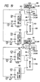
- the fundamental system of the embodiment 5 is substantially the same as the fourth embodiment and can be realized by replacing the horizontal counter 211 and vertical counter 212 in Fig. 3 to counters shown in Fig. 19.
- the system of Fig. 19 comprises: a horizontal up counter 801; a horizontal down counter 802; a vertical up counter 803; a vertical down counter 804; OR gates 805, 806, 807′, 811, and 817; AND gates 810 and 816; EXOR gates 813 and 819; frequency demultipliers 808 and 814; D flip-flops (D F/F) 809 and 815; and selectors 812 and 818.
- the texture pattern has a size of n x m
- a waveform is formed by the frequency demultiplier so as to select the address of the down counter by a selector (a (a′) in Fig. 20).
- the values set by the CPU 108 are loaded into the counters, respectively, (load pulse in Fig. 20).
- ⁇ is loaded into the horizontal up counter 801 and n/2 is loaded into the horizontal down counter 802.
- Fig. 21 is a diagram showing the case where the above operation is applied in the horizontal and vertical directions. Due to this, even if the pattern of Fig. 17A is the read pattern, a pattern as shown in Fig. 17C can be read out.
- the concentration modulation has been executed to the multivalue color image data by using the multivalue single color concentration data.
- the concentration modulation is executed by using the multivalue color image data.
- the texture processing unit in Fig. 2 from which the calculator (1) to execute the mean value process of each color component is omitted is provided for each color component of R, G, and B (900, 901, 902), thereby enabling the texture process to be executed every color component.
- Each of the texture processing units 900 to 902 has a construction similar to that in the case of Fig. 2.
- the address signal of the memory and the enable signal can be commonly used for the R, G, and B signals. In such a case, the counters and the like can be commonly used.
- the embodiment can be also applied to the embodiments 1 to 5. According to the embodiment 6, since the mutual calculations among the multivalue color image data are executed, the effect of the texture process becomes typical.
- a printer which can output a color image such as color laser printer, color ink jet printer, color dot printer, color thermal copy transfer printer, color printer using a recording material responsive to three primary colors of light, etc. can be used as a printer unit 116 which is used in the invention.
- the construction of the texture process for executing the concentration modulation to the color image input in a real-time manner has been shown.
- a white and black image may be also used as an image which is subjected to the texture process.
- both of the texture pattern and the image to be texture processed use the multivalue data.
- either one or both of them can use binary data.
- arithmetic operating circuits such as adder, AND circuit, OR circuit, etc. can be also used in place of the multipliers.
- a method of forming the pattern data is not limited to (R + G + B)/3. That is, the pattern data can be formed on the basis of the maximum or minimum value among the R, G, and B signals.
- Image inputting means is not limited to the CCD but, for instance, external inputting means such as still video camera, video camera, or the like can be also used.
- the memory to store the pattern data is not limited to the RAM but memory means such as a magnetic disk or the like can be also used.
Abstract
Description
- The present invention relates to an image processing apparatus for concentration modulating input image data.
- Hitherto, an apparatus which can execute a process (hereinafter, referred to as a texture process) for concentration modulating image data by using arbitrary pattern data is limited to a relatively large scale computer. The texture process will now be briefly described. For instance, the texture process denotes that an input image as shown in Fig. 7A is concentration modulated by using pattern data as shown in Fig. 7B, so that an output image as shown in Fig. 7C is obtained. Assuming that the texture pattern of Fig. 7B is a pattern of a cloth design, the cloth pattern can be synthesized to the area in the L-shaped character of Fig. 7A.
- In an image processing apparatus for outputting an image from an image input in a real-time manner, the apparatus which can execute such a texture process does not exist.
- On the other hand, hitherto, in the case of executing the texture process to a plurality of areas, the process must be sequentially executed every area and it is troublesome. Therefore, even in the case of synthesizing the same texture pattern to a plurality of areas, it takes a time in proportion to the number of areas.
- In addition, even in the case of executing the texture process to a non-rectangular area instead of a rectangular area, a mask must be produced to designate such an area, so that it is very complicated.
- Further, in the case of variably magnifying a texture pattern and executing the concentration modulation to the input image data, after the variably magnifying process was executed to the texture pattern every process, the texture process must be performed, so that it is troublesome.
- On the other hand, for instance, an apparatus of a construction as shown in Fig. 1 is considered as a method of realizing that the texture process is executed to an input image in a real-time manner. That is, according to the method, a pattern image for the texture process is previously read and stored, and when an original image which is subjected to the texture process is read, the stored pattern image is read out and calculated by an image modulator and the concentration is modulated.
- However, in such an apparatus, since there is a limitation in the capacity of a memory unit to store the pattern image for the texture process, if the pattern image to be processed is smaller than the original image data to be processed, the pattern image must be repetitively used.
- In the case of repetitively using the pattern image as mentioned above, no problem occurs for an image such that the patterns are relatively continuous at the right/left and upper/lower joint surfaces of the pattern image. However, in many cases, since the patterns at the joint surfaces are discontinuous, there is a drawback such that the image after completion of the texture process suddenly changes at the joint surfaces of the pattern and an unnatural line of the concentration difference appears in the image. For instance, Fig. 16A shows a finite size pattern. Fig. 16B shows concentration difference lines which are generated when the texture process of the repetitive pattern was executed to an area larger than the size of the finite size pattern of Fig. 16A.
- Such a drawback inevitably occurs in the image process for concentration modulating an image in accordance with a certain pattern.
- The present invention is made in consideration of the above conventional technique and it is the first object of the invention to provide an image processing apparatus which can execute the texture process in a real-time manner.
- To accomplish the above object, according to the first invention of the patent application, there is provided an invention in which by providing means for producing at least one area signal, particularly, a non-rectangular area signal, a texture process is executed to at least one area and the result can be output in a real-time manner.
- The second object of the invention is to provide an image processing apparatus which can execute a variety of texture processes.
- To accomplish the second object, according to the second invention of the patent application, there is provided an invention in which by providing means for storing a modulation pattern and means for controlling addresses of a memory to store the modulation pattern, variably magnifying processes which are different in the horizontal and vertical directions are executed independently of image data to be modulated, texture processes are executed, and the result can be output in a real-time manner.
- The third object of the invention is to provide an image processing apparatus which can prevent a deterioration in picture quality when a texture process is executed.
- To accomplish the third object, the third invention of the patent application comprises: input means for inputting first image data; memory means for storing the first image data; means for executing a proper process to the first image data; input means for inputting second image data; and means for modulating a concentration of the second image data by an output from the means for executing the proper process.
- The above and other objects and features of the present invention will become apparent from the following detailed description and the appended claims with reference to the accompanying drawings.
-
- Fig. 1 is a whole block diagram of an image processing apparatus of the first embodiment of the present invention;
- Fig. 2 is a diagram for explaining a texture processing circuit;
- Fig. 3 is an explanatory diagram of an area generating
circuit 111; - Figs. 4A and 4B are diagrams showing a practical example of a texture process;
- Fig. 5 is an explanatory diagram of the
area generating circuit 111 in the second embodiment of the invention; - Figs. 6A and 6B are diagrams showing a practical example of a texture process in the second embodiment of the invention;
- Figs. 7A to 7C are diagrams showing the relation between the texture and the modulation pattern;
- Fig. 8 is a whole block diagram of an image processing apparatus in the third embodiment of the invention;
- Figs. 9-1 and 9-2 are block diagrams of image modulators;
- Figs. 10-1 and 10-2 are flowcharts for the operation of the image processing apparatus of the third embodiment of the invention;
- Fig. 11-1 is a constructional diagram of an RAM for a texture pattern;
- Fig. 11-2 is a diagram showing a method of calculating coordinates for a filtering process;
- Fig. 11-3 is a diagram showing a practical example of the calculation of the coordinates for the filtering process;
- Fig. 12-1 is a diagram showing a range which is subjected to the filtering process;
- Fig. 12-2 is a diagram showing an example of a smoothing filter which is used in the filtering process;
- Fig. 12-3 is a diagram showing a texture pattern before the filtering process is executed;
- Fig. 12-4 is a diagram showing the texture pattern after completion of the filtering process;
- Fig. 13-1 is a diagram showing the case where the texture pattern before the filtering process was repeated;
- Fig. 13-2 is a diagram showing the case where the texture pattern after completion of the filtering process was repeated;
- Fig. 14 is a diagram showing a filter matrix;
- Fig. 15 is a diagram showing an algorithm of the fourth embodiment of the invention;
- Figs. 16A to 16C are diagrams for explaining a problem in the conventional texture process;
- Figs. 17A to 17C are diagrams for explaining a practical example of the texture process in the embodiment;
- Figs. 18A and 18B are diagrams showing states of a pattern memory in the fourth embodiment of the invention;
- Fig. 19 is a block diagram of the fifth embodiment of the invention;
- Fig. 20 is a diagram showing pulses for the texture process according to the fifth embodiment of the invention;
- Fig. 21 is a diagram showing counters which are used in the texture process in the fifth embodiment of the invention; and
- Fig. 22 is a diagram showing the sixth embodiment of the invention.
- Fig. 1 is a block diagram including a texture process of a color copying apparatus as an image processing apparatus of the embodiment. The apparatus of the embodiment comprises: a
CPU 108 for processing and calculating which is connected to aCPU bus 117; anROM 109 in which programs for the texture process and the like are previously stored; anRAM 110 for auxiliary storage which is used as a work area; aCCD 100 to read image data; an A/D conversion unit 101 for converting an analog signal into a digital signal; acolor masking unit 102; an undercolor removing unit or undercolor removal unit (hereinafter, simply referred to as an UCR unit) 103 for removing the undercolor from output data 123 of thecolor masking unit 102; agradation correction unit 104 to execute the gamma conversion to imagedata 124; anoperation unit 105 to execute various inputs; animage modulator 114 to execute the texture process on the basis ofimage data 120 and data of anRAM 113; anarea generation circuit 111 to generate an area signal (particularly, the area signal is used as an enable signal of acounter 112 and an enable signal of the texture process); an enlargement/reduction unit 115 to execute an enlarging/reducing process in the horizontal direction to imagedata 126; and aprinter unit 116 to output a final hard copy. Adigitizer 106 is connected to the apparatus through a serial I/F 107. - A color laser beam printer is used as a
printer unit 106 in the example. Theprinter unit 106 sequentially develops the colors of Y (yellow), M (magenta), C (cyan), and K (black) and obtains a full-color image output. - Fig. 3 is an explanatory diagram of the
area generation circuit 111. Thearea designation circuit 111 comprises: acounter 300 which is counted up by the input of an image clock VCK and is reset by the input of a horizontal sync signal HSYNC and outputs acount signal 304;comparators digitizer 106; and a JK flip-flop (JK F/F) 303 which executes the toggling operation on the basis of outputs of the twocomparators of the number as many as only the number of areas.
- Fig. 2 is a diagram for explaining a texture processing circuit as a characteristic section of the invention. Explanation will now be made individually hereinbelow with respect to a writing unit to write modulation data (texture pattern) 218 into the
RAM 113 and a calculating unit (texture processing unit) ofdata 216 from theRAM 113 andimage data 215 which is subjected to the texture process. - A calculator (1) 201 comprises: luminance to concentration converters for receiving input signals of R (red), G (green), and B (blue) and outputting signals of Y (yellow), M (magenta), and C (cyan); and a YMC mean value circuit. For RGB input signals 122, (Y + M + C)/3, that is
concentration data 219 of eight bits is obtained. Theconcentration data 219 is input to the B side of aselector 200. On the other hand, data of eight bits is input to the A side of theselector 200 through theCPU bus 117. This 8-bit data is the video data and is the read image data which is not transmitted through the calculator (1) 201. When data is written into the memory, theselector 200 selects the concentration data on the B side in response to an instruction of theCPU 108. Then, aselector 202 selects the A side. - On the other hand, an OR
circuit 207 calculates the OR of the enable signal 128 and the VCK. Aselector 208 selects the B side by an instruction of theCPU 108. To write the modulation pattern into thememory 113, asignal 220 is input as an enable signal to aWE input terminal of thememory 113 and to adriver 203. - A memory address signal is produced by a
vertical counter 212 which is counted up synchronously with the horizontal sync signal HSYNC and ahorizontal counter 211 which is counted up synchronously with the image clock VCK. Aselector 210 selects the B side and the selected memory address signal is input to an address in thememory 113. - As mentioned above, the concentration pattern of the input image is written into the
memory 113. In general, for such a pattern, the position of an original is designated by thedigitizer 106 and theCCD 100 then the pattern of the designated position is written into thememory 113. - In the case where the modulation data from the
CPU 108 is written into thememory 113, theselector 202 selects the B side to input the CPU data. On the other hand, theselector 208 selects theWE signal of the CPU on the A side. TheWE signal is input asWE of thememory 113 and an enable signal of thedriver 203. For the memory address, the CPU address signal on the A side is selected by theselector 210 and is input to an address in thememory 113. In this manner, by switching the addresses in the case where the pattern data from the reader is stored into thememory 113 and the case where the pattern data from theCPU 108 is stored, the pattern data even from any input can be stored. As mentioned above, an arbitrary concentration pattern is written into thememory 113. (Calculating unit ofdata 216 of theRAM 113 and image data 215) - The above calculation is realized by a calculator (2) 215. The calculator (2) comprises a multiplier. The calculation of the
data area generation circuit 111 is active, so that the texture process is executed. When the enable signal 218 is disenable, thedata 215 is set to the through state, so that theimage data 126 of eight bits which is not subjected to the texture process is output. - When the texture process is executed to the broken line areaof an image as shown in Fig. 4A, the OR of the area signals of ① to ③ is input as an enable signal, so that an output image as shown in Fig. 4B can be obtained. It is now assumed that the modulation pattern is as shown in Fig. 7B.

- As mentioned above, by calculating the OR of a plurality of area signals, the process to synthesize the same texture pattern can be executed by merely adding a procedure to designate a plurality of areas. (Calculating unit of
data 216 of theRAM 113 and image data 215) - The calculation to synthesize the data (texture pattern data) 216 of the
RAM 113 and theimage data 215 is realized by the calculator (2) 215. The calculator (2) comprises a multiplier. The calculation of thedata 216 of the calculator and thedata 215 is executed in only the portion where the enable signal 218 to control whether the texture process is executed or not is active. When thesignal 218 is disenable, thedata 215 is set to the through state. - The
input image data 215 is thedata 120 on the A side which is selected by theselector 200, that is, the video data. Anotherinput data 216 is the texture pattern data which is output from thememory 113. In a manner similar to the writing mode, when the data from thememory 113 is read out as well, in the case wherepattern data 219 from the CCD has been stored, the address control is executed by using thehorizontal counter 211 andvertical counter 212 on the B side of theselector 210. When the pattern data from theCPU 108 has been stored, the CPU address on the A side of theselector 210 is used. - A method of variably magnifying the modulation data (texture pattern data) independently of the input image data will now be described.
- The reducing process is executed when
image data 217 is written into thememory 113. Data are set into two r.m.p. (rate multipliers) 213 and 214 by theCPU 108 so that the image clocks VCK are thinned out by the r.m.p. 213 and the horizontal sync signals HSYNC are thinned out by the r.m.p. 214. Due to this, the counting-up speeds of thehorizontal counter 211 andvertical counter 212 become slow, so that the reduced data is written into thememory 113. When the calculation of thedata 216 of theRAM 113 and theimage data 215 is executed (when the texture process is performed), data are set into the r.m.p. 213 and 214 from theCPU 108 so that the VCK and HSYNC are not thinned out, respectively. - On the contrary, when image data is written into the
memory 113, data are respectively set into the r.m.p. 213 and 214 by theCPU 108 so that the clocks which are not thinned out are set into the two counters. - When the calculation of the
data 216 of theRAM 113 and theimage data 215 is executed (when the texture process is performed), data are respectively set into the two r.m.p. so that the VCK and HSYNC are thinned out. Due to this, the counting-up speeds of the two address counters become slow, so that the texture pattern is modulated in an enlarged form. - Although the same enlarging/reducing processes in the horizontal and vertical directions have been executed in the above embodiment for simplicity of explanation, since the r.m.p. is independently provided for each process, by changing the data which are set into the r.m.p. 213 and 214, it is possible to independently variably magnify in the horizontal and vertical directions in a manner such as to enlarge in only the horizontal direction and to reduce in only the vertical direction, or to reduce in the horizontal direction and to enlarge in only the vertical direction, or the like.
- By repeating the counting operations until certain values of the
horizontal counter 211 andvertical counter 212, the same pattern is repeated and the texture process can be executed. - On the other hand, a fineness of the repetitive pattern can be arbitrarily determined by the above enlarging and reducing processes.
- The fundamental construction is similar to Fig. 1. Only a different point relates to a construction of the
area generation circuit 111. In the embodiment, thearea generation circuit 111 comprises the circuits shown in Figs. 3 and 5. - Fig. 5 will now be described. The
area generation circuit 111 outputs a "1" signal from an ANDgate 507 when the area signal generated from the circuit of Fig. 3 is set to 1 and when color separation data R (122-1), G (122-2), and B (122-3) of the input image data lie within a predetermined luminance range which has been preset by theCPU 108.Reference numeral 511 denotes a timing circuit which is provided to synchronize the enablesignal 128. With the above construction, from an original as shown in Fig. 6A such that red characters are drawn on a green background, an output image in which the texture process was executed to only the red character portion as shown in Fig. 6B can be obtained. A modulation pattern as shown in Fig. 7B is used here. - By providing the circuit as shown in Fig. 5, the non-rectangular texture process can be executed without using a memory to designate an area although it is difficult to adjust the timing.
- As described above, according to the apparatus of the embodiment, the texture process can be easily executed to at least one area, particularly, a non-rectangular area in a real-time manner. The apparatus can be widely applied to the design field.
- On the other hand, since the modulation pattern can be variably magnified independently of the image data to be modulated, the image data can be easily modulated by the variably magnified modulation pattern in a real-time manner. There is an advantage such that the apparatus can be widely applied to the design field.
- According to the third embodiment of the invention which will be explained hereinlater, by executing a filtering process to an area near the outer frame portion of the pattern image for the texture process, particularly, since the memory unit to store the pattern image has a limited size, in the case where the pattern image must be continuously used or the like, the discontinuity at the joint surfaces of the images in the right/left and upper/lower positions is weakened, thereby enabling the image process to be more continuously executed.
- Fig. 8 is a block diagram including the texture process in the image processing apparatus of the embodiment of the invention. A fundamental construction of the image processing apparatus in the embodiment is also similar to that in Fig. 1. Therefore, the description of each section is omitted.
- Fig. 9-1 is a diagram for explaining a texture processing circuit. Since a construction of Fig. 9-1 is also similar to Fig. 2, its description is omitted.
- The image processing apparatus using the invention includes the operation unit (105 in Fig. 8) having: means (key input means) for selecting the texture mode; and means (key input means) for making the effect of the filtering process of the invention operative or inoperative in the texture process. Each means can set, check, and change. When the texture mode is selected by the mode selecting key, the operating mode is set to the texture processing mode from the ordinary processing mode.
- The operation of the invention will now be described herein below.
- Fig. 10-1 is a flowchart showing an outline of the operation of the apparatus.
- First, an operation command is input from the operation unit 105 (step S-400). A check is made to see if the operation command is a copy start command or not. If it is not the copy start command, a check is made to see if the operation command is a texture pattern reading command or not (S-402). If the operation command is the texture pattern reading command (S-403), an original is scanned and the image data obtained is stored into the texture pattern RAM 113 (S-408). On the other hand, if the operating command is not the reading command, a check is made to see if the operating command indicates to execute other process or not (S-405). If YES, the other process is executed (S-407). When the reading operation is finished, if the execution of the filtering process is not set (S-410), the apparatus again waits for the input of the operation command (S-400). If the execution of the filtering process has been set (S-409), the filtering process as will be explained hereinlater is performed.
- A general filter of an average in a block as shown in Fig. 12-2 is used as a smoothing filter.
- For instance, it is now assumed that a size of
RAM 113 for the texture pattern is set to 512 dots x 512 dots as shown in Fig. 11-1. - When executing the filtering process to the
RAM 113 by a matrix of 3 x 3, the address calculations of the memory are as shown in Fig. 11-2. - Fig. 11-2 shows a matrix of 3 x 3 indicative of the addresses in the memory.
- If all of total nine pixels of 3 x 3 which are used in the filtering process lie within an area of 512 dots x 512 dots, the filtering process can be directly executed. However, in the case of filtering the outer peripheral portion of the texture pattern, some of the nine pixels are deviated out of the area of 512 dots x 512 dots. Therefore, in such a case, the address calculations are executed by setting as follows with respect to the x and y directions, respectively.

- Fig. 11-3 shows a practical example. As shown in the diagram, to execute the filtering process to (1, 1), it is necessary to use the texture data of x = 512 or y = 512. Therefore, all of the texture data are first stored into the
RAM 113 and some of the texture data which are necessary to the filtering process are input to theCPU 108 and calculated on the basis of the address calculations mentioned above. That is, when the images each having the size of 512 dots x 512 dots are arranged, the calculation is executed with respect to the adjacent pixels at the edges of the image patterns. - The operation which is executed in the circuit of Fig. 9-1 will be described with reference to a flowchart for the
CPU 108 in Fig. 10-2. The texture pattern data which was set through theselector 202 is now stored in theRAM 113. First, the first block data of 3 x 3 pixels (Fig. 12-2) is read out of theRAM 113 and is input to theCPU 108 through thedrivers 204 and 206 (S-500). The calculation is executed in accordance with the smoothing calculating equation shown in Fig. 12-2 (S-501). The result of the calculation is written as a value of a central pixel e into theRAM 113 through thedriver 205,selector 202, and driver 203 (S-502). In the address control of theRAM 113 in such a case, an address control signal of theCPU 108 on the A side of theselector 210 is used. The above calculation is sequentially executed (S-503) with respect to the hatched area in Fig. 12-1, which will be explained later, that is, the peripheral area of the texture pattern. - In the above example, the smoothing calculation has been performed every pixel (refer to S-503). However, it is also possible to construct such that all of the data in the
RAM 113 are read out and input to theCPU 108 and the calculations are executed in a lump and the results of the calculations are sequentially written into theRAM 113. On the other hand, as shown in Fig. 9-2, it is also possible to construct in a manner such that a smoothingcircuit 600 to execute the smoothing calculation as shown in Fig. 12-2 is provided for the hardware construction and the enable control is performed by theCPU 108 so as to execute the smoothing process with respect to a predetermined area. - The filtering process is executed to the area near the outer frame of the texture pattern as shown in Fig. 12-1. The filtering process is performed to only the portion in a range from the pixel of the outermost position to the pixel which is inside therefrom by only a proper number of pixels. If a width of such a portion is narrowed, the effect decreases. However, if the width is set to be too wide, the effect of the texture process is reduced. The width corresponding to the number of pixels can be set to be large or small by the
operation unit 105. TheCPU 108 changes the size of area which is subjected to the smoothing process in accordance with the setting of such a width by theoperation unit 105. Fig. 12-4 shows the result in the case where the area near the outer frame of the pattern shown in Fig. 12-3 was subjected to the filtering process. Figs. 13-1 and 13-2 show the patterns in which the areas which were subjected to the filtering process are repetitively arranged. Although the drawings relate to the case where the pattern has been repeated only in the lateral direction, the effect similar to the case of the lateral direction can be also obtained with regard to the vertical direction. - On the other hand, if the operation command is a copy start command (S-401), a check is made to see if the texture process has been selected or not. If the texture process has been selected (S-412), the
image modulator 114 is made operative. If the texture process is not selected (S-413), the operating mode of theimage modulator 114 is set to the image through mode and the ordinary original reading operation is executed (S-416). - In the embodiment, the matrix of 3 x 3 has been used to execute the filtering process. However, the matrix size is not limited to 3 x 3. A matrix of 5 x 5, 7 x 7, or the like can be also used.
- The width of the area which is subjected to the filtering process, that is, the width of the hatched area of Fig. 12-1 can be properly determined in accordance with a degree of a desired filtering effect. On the other hand, it is also possible to execute the filtering process in only the vertical or lateral direction.
- Further, the kind of filter is not limited to the average in the matrix but can be also set to the maximum value (Fig. 8), minimum value, or the like in the matrix.
- As mentioned above, according to the embodiment, as the result of that a sample image for the texture process was repetitively arranged, if the joint surfaces of the sample images become unnatural, by executing the filtering process to the outside frame portion of the sample image, a situation such that the process unnaturally changes at the joint surfaces can be avoided. Even in the case where the memory size of the sample image is relatively small, the natural texture effect can be also derived.
- As described above, according to the embodiment, by providing,
inputting means (CCD 100 or the like) for inputting first image data,
memory means (RAM 113) for storing the first image data,
means (image modulator 114) for executing the filtering process to the first image data, and
means (image modulator 114) for modulating a concentration of the second image data by an output from the means for executing the filtering process,
the generation of the lines of the concentration difference due to a sudden change in concentration when the concentration modulation is executed to the image data can be prevented. - The above embodiment has been described with respect to the filtering process in the case of executing the texture process by using a repetitive pattern. However, even in the case of using the repetitive pattern, when the texture process is executed to a part of the original image, an effect such that the boundary with the non-processing portion becomes smooth can be obtained.
- In a manner similar to the
embodiment 3, the embodiment 4 also intends to prevent the concentration different lines which are generated when a texture pattern is repeated. In the embodiment, such an object is accomplished by the folding-back process of the data in thetexture pattern memory 113. - A whole construction of the fourth embodiment of the invention is similar to Fig. 1. In addition, since the circuits to execute the texture process are also substantially similar to those in Fig. 3, their descriptions are omitted.
- Fig. 15 is a diagram for explaining an algorithm of the embodiment.
- In
step 1, a concentration pattern (texture pattern) of an original put on an original base is read. The reading operation is similar to that in the case of the first embodiment. - In
step 2, a folding-back operation, which will be explained later, is executed to the memory into which the read pattern was stored. A pattern which is point symmetrical with respect the center of the memory as an origin is formed. Figs. 17A to 17C, 18A, and 18B are diagrams for explaining a practical example. - Assuming that the pattern memory size is set to n x m, first, the following substitution is executed (Fig. 18A).
P(x, y) → P(n+1-x, y)
where, x = 1 to n/2, y = 1 to m/2
Thus, the content of the pattern memory becomes as shown in Fig. 17B. - Next, the following substitution is performed (Fig. 18B).
P(x, y) → P(x, m+1-y)
where, x = 1 to n, y = 1 to m/2
Thus, the content of the pattern memory becomes as shown in Fig. 17C. A pattern which is point symmetrical with respect to the center of the memory as an origin is produced. The above process is executed in accordance with a procedure of the program of theCPU 108. The operation of the texture processing circuit (Fig. 2) is similar to the case of theembodiment 3. - In
step 3, the texture process is executed by the pattern produced. - In the pattern produced, the concentrations of the left, right, upper, and lower edges are equally repeated. Even if the patterns are arranged in the upper, lower, right, and lift positions, no concentration variation occurs at the boundaries.
- Therefore, if the texture process is executed by using the produced pattern, even if a texture pattern of a limit size is used, the texture process such as not to cause any concentration different line at the boundaries is executed and a good image pattern can be output.
- That is, for instance, if the texture pattern as shown in Fig. 16A is read, the texture process is executed by the pattern as shown in Fig. 16C.
- In the embodiment, a point symmetrical pattern has been used as a pattern for the concentration modulation. However, by executing the similar process, a line symmetrical pattern is generated and the concentration modulation can be also executed on the basis of the line symmetrical pattern. In this case, it is possible to execute the texture process having no concentration different line with respect to at least either the vertical or lateral direction.
- The
embodiment 5 relates to the case where when a texture pattern is read, that is, when the concentration modulation is executed, a pattern which is point symmetrical with respect to the center of the pattern as an origin is read out. - The fundamental system of the
embodiment 5 is substantially the same as the fourth embodiment and can be realized by replacing thehorizontal counter 211 andvertical counter 212 in Fig. 3 to counters shown in Fig. 19. - The system of Fig. 19 comprises: a horizontal up counter 801; a horizontal down
counter 802; a vertical upcounter 803; avertical down counter 804; ORgates gates EXOR gates selectors - Since horizontal and vertical counters have substantially the same construction except that the clocks are different, explanation will now be made by using the horizontal counters hereinafter.
- Assuming that the texture pattern has a size of n x m, first, when the address of the up counter is equal to or larger than the length of 1/2 of the pattern size (until n/2 in the horizontal direction), a waveform is formed by the frequency demultiplier so as to select the address of the down counter by a selector (a (a′) in Fig. 20). At the changing point of the selection of the counter, the values set by the
CPU 108 are loaded into the counters, respectively, (load pulse in Fig. 20). Practically speaking, ø is loaded into the horizontal up counter 801 and n/2 is loaded into the horizontal downcounter 802. - Fig. 21 is a diagram showing the case where the above operation is applied in the horizontal and vertical directions. Due to this, even if the pattern of Fig. 17A is the read pattern, a pattern as shown in Fig. 17C can be read out.
- When the pattern is read, by using ø as a register value which is set into the
gates - As described above, by generating a pattern which is point symmetrical with respect to the center of a texture pattern of a limited size, it is possible to provide a cheap image processing apparatus of a high performance which can reduce the concentration diffferent line of the boundary portions which are generated in the case of executing the texture process to an area larger than the size of the pattern memory by using the pattern memory of the limited size.
- In the
above embodiments 1 to 5, the concentration modulation has been executed to the multivalue color image data by using the multivalue single color concentration data. However, in the sixth embodiment, the concentration modulation is executed by using the multivalue color image data. - Therefore, as shown in Fig. 22, in the embodiment, the texture processing unit in Fig. 2 from which the calculator (1) to execute the mean value process of each color component is omitted is provided for each color component of R, G, and B (900, 901, 902), thereby enabling the texture process to be executed every color component. Each of the
texture processing units 900 to 902 has a construction similar to that in the case of Fig. 2. The address signal of the memory and the enable signal can be commonly used for the R, G, and B signals. In such a case, the counters and the like can be commonly used. - The embodiment can be also applied to the
embodiments 1 to 5. According to theembodiment 6, since the mutual calculations among the multivalue color image data are executed, the effect of the texture process becomes typical. - A printer which can output a color image such as color laser printer, color ink jet printer, color dot printer, color thermal copy transfer printer, color printer using a recording material responsive to three primary colors of light, etc. can be used as a
printer unit 116 which is used in the invention. - In the embodiments, the construction of the texture process for executing the concentration modulation to the color image input in a real-time manner has been shown. However, a white and black image may be also used as an image which is subjected to the texture process.
- In the above embodiment, both of the texture pattern and the image to be texture processed use the multivalue data. However, either one or both of them can use binary data.
- Various kinds of arithmetic operating circuits such as adder, AND circuit, OR circuit, etc. can be also used in place of the multipliers.
- A method of forming the pattern data is not limited to (R + G + B)/3. That is, the pattern data can be formed on the basis of the maximum or minimum value among the R, G, and B signals.
- Image inputting means is not limited to the CCD but, for instance, external inputting means such as still video camera, video camera, or the like can be also used.
- The memory to store the pattern data is not limited to the RAM but memory means such as a magnetic disk or the like can be also used.
- The present invention is not limited to the foregoing embodiments but many modifications and variations are possible within the spirit and scope of the appended claims of the invention.
Claims (36)
inputting means for inputting image data;
memory means for storing first image data which is input by said inputting means; and
processing means for executing a modulating process to at least one area of second image data which is input by the inputting means by using the first image data stored in said memory means.
inputting means for inputting image data;
memory means for storing first image data which is input by said inputting means; and
processing means for variably magnifying the first image data stored in said memory means and modulating a concentration of second image data which is input by said inputting means.
and wherein said area is specified by the color detected by said detecting means.
inputting means for inputting image data;
memory means for storing first image data input by said inputting means;
filtering processing means for executing a filtering process to the first image data; and
modulating means for modulating second image data input by said inputting means by using an output of said filtering processing means.
inputting means for inputting image data;
memory means for storing first image data input by said inputting means;
modulating means for modulating second image data input by said inputting means by repetitively using the first image data; and
processing means for eliminating discontinuity in a boundary portion of the first image data.
inputting means for inputting a plurality of color component signals;
memory means for storing multivalue concentration data which is obtained on the basis of the color component signals input by said inputting means; and
calculating means for executing a calculation by using the color component signals input by said inputting means and the concentration data stored in said memory means.
storing first image data;
inputting second image data; and
sequentially mutually calculating said first and second image data every pixel while reading out the first image data every pixel.
designating an area in an image which is expressed by said second image data,
and wherein in said calculating step, said mutual calculation is executed with respect to only the area designated in said area designating step.
Applications Claiming Priority (6)
| Application Number | Priority Date | Filing Date | Title |
|---|---|---|---|
| JP63287093A JP3004993B2 (en) | 1988-11-14 | 1988-11-14 | Image processing device |
| JP287093/88 | 1988-11-14 | ||
| JP291564/88 | 1988-11-18 | ||
| JP63291564A JP2728904B2 (en) | 1988-11-18 | 1988-11-18 | Image processing device |
| JP35349/89 | 1989-02-14 | ||
| JP1035349A JPH02214257A (en) | 1989-02-14 | 1989-02-14 | Picture processor |
Publications (3)
| Publication Number | Publication Date |
|---|---|
| EP0369719A2 true EP0369719A2 (en) | 1990-05-23 |
| EP0369719A3 EP0369719A3 (en) | 1991-04-24 |
| EP0369719B1 EP0369719B1 (en) | 1998-01-21 |
Family
ID=27288736
Family Applications (1)
| Application Number | Title | Priority Date | Filing Date |
|---|---|---|---|
| EP89311742A Expired - Lifetime EP0369719B1 (en) | 1988-11-14 | 1989-11-14 | Image processing apparatus and method |
Country Status (4)
| Country | Link |
|---|---|
| US (1) | US5021876A (en) |
| EP (1) | EP0369719B1 (en) |
| DE (1) | DE68928557T2 (en) |
| ES (1) | ES2110950T3 (en) |
Cited By (2)
| Publication number | Priority date | Publication date | Assignee | Title |
|---|---|---|---|---|
| AU745107B2 (en) * | 1998-11-30 | 2002-03-14 | Canon Kabushiki Kaisha | Texture advisor |
| US6751339B1 (en) | 1998-11-30 | 2004-06-15 | Canon Kabushiki Kaisha | Texture advisor |
Families Citing this family (25)
| Publication number | Priority date | Publication date | Assignee | Title |
|---|---|---|---|---|
| JP2802062B2 (en) * | 1987-07-22 | 1998-09-21 | 株式会社リコー | Digital color copier |
| JP3039658B2 (en) * | 1989-05-10 | 2000-05-08 | キヤノン株式会社 | Image processing apparatus and method |
| JP2886924B2 (en) | 1990-01-25 | 1999-04-26 | キヤノン株式会社 | Image processing device |
| EP0446008B1 (en) * | 1990-03-05 | 1996-10-16 | Canon Kabushiki Kaisha | Image processing method and apparatus |
| JP3029118B2 (en) * | 1990-04-27 | 2000-04-04 | キヤノン株式会社 | Color image forming equipment |
| DE69227853T2 (en) * | 1991-03-01 | 1999-05-27 | Canon Kk | Image processing device |
| US5499113A (en) * | 1991-03-19 | 1996-03-12 | Minolta Camera Kabushiki Kaisha | Image data processing system with still video camera and digital image forming apparatus |
| JP3347339B2 (en) | 1991-04-08 | 2002-11-20 | キヤノン株式会社 | Image processing device |
| JP3082289B2 (en) * | 1991-05-14 | 2000-08-28 | 富士ゼロックス株式会社 | Image processing device |
| JP3320100B2 (en) * | 1991-07-19 | 2002-09-03 | キヤノン株式会社 | Image processing method and apparatus |
| JPH06223168A (en) * | 1992-04-29 | 1994-08-12 | Canon Inf Syst Res Australia Pty Ltd | Mixture and generation system of color as well as graphics system |
| JP3230535B2 (en) * | 1992-04-30 | 2001-11-19 | キヤノン株式会社 | Image processing device |
| US5610997A (en) * | 1992-07-28 | 1997-03-11 | Canon Kabushiki Kaisha | Image processing method and apparatus |
| US6421145B1 (en) * | 1992-09-28 | 2002-07-16 | Canon Kabushiki Kaisha | Image processing apparatus and method using image information and additional information or an additional pattern added thereto or superposed thereon |
| US5692229A (en) * | 1993-05-31 | 1997-11-25 | Canon Kabushiki Kaisha | Image forming system which superimposes additional information on an image signal |
| JP3337768B2 (en) * | 1993-07-23 | 2002-10-21 | キヤノン株式会社 | Composite image forming apparatus and method of controlling composite image forming apparatus |
| US6031631A (en) * | 1993-09-03 | 2000-02-29 | Canon Kabushiki Kaisha | Image processing system with independent control of image forming apparatuses |
| JP3110924B2 (en) * | 1993-09-30 | 2000-11-20 | キヤノン株式会社 | Image forming device |
| US5581359A (en) * | 1993-09-30 | 1996-12-03 | Canon Kabushiki Kaisha | Image processing apparatus and method |
| US6515769B1 (en) | 1993-10-29 | 2003-02-04 | Canon Kabushiki Kaisha | Image forming apparatus and method |
| JPH07147639A (en) * | 1993-11-22 | 1995-06-06 | Canon Inc | Device and system for forming image |
| JP3566334B2 (en) * | 1994-03-25 | 2004-09-15 | キヤノン株式会社 | Image processing apparatus and method |
| JPH08195878A (en) | 1995-01-18 | 1996-07-30 | Canon Inc | Image processor |
| JP4478222B2 (en) | 1997-09-24 | 2010-06-09 | キヤノン株式会社 | Image forming system, image forming apparatus, and control method thereof |
| US7433091B2 (en) * | 2002-11-28 | 2008-10-07 | Canon Kabushiki Kaisha | Image forming and reading apparatus |
Citations (4)
| Publication number | Priority date | Publication date | Assignee | Title |
|---|---|---|---|---|
| US4106416A (en) * | 1976-12-02 | 1978-08-15 | Westpoint Pepperell, Inc. | Control apparatus for textile dyeing and tufting machinery |
| US4297691A (en) * | 1978-08-30 | 1981-10-27 | Hitachi, Ltd. | Figure displaying device |
| US4646078A (en) * | 1984-09-06 | 1987-02-24 | Tektronix, Inc. | Graphics display rapid pattern fill using undisplayed frame buffer memory |
| GB2218295A (en) * | 1988-08-11 | 1989-11-08 | Graphic Palette Company Ltd | 2-D to 3-D image transformation |
Family Cites Families (9)
| Publication number | Priority date | Publication date | Assignee | Title |
|---|---|---|---|---|
| US4403249A (en) * | 1978-02-21 | 1983-09-06 | Dr. Ing. Rudolf Hell Gmbh. | Apparatus for mixing image signals to obtain a printing master |
| GB2089165B (en) * | 1980-10-30 | 1985-10-09 | Canon Kk | Character and image processing |
| JPS57150274A (en) * | 1981-03-13 | 1982-09-17 | Fuji Xerox Co Ltd | Image output device |
| DE3486434T2 (en) * | 1983-03-08 | 1996-12-19 | Canon Kk | Imaging device |
| US4714940A (en) * | 1983-08-16 | 1987-12-22 | Canon Kabushiki Kaisha | Image processing apparatus having display means to monitor and display information from a date input section |
| JPS60106267A (en) * | 1983-11-15 | 1985-06-11 | Canon Inc | Copy recorder |
| US4731672A (en) * | 1983-11-25 | 1988-03-15 | Canon Kabushiki Kaisha | Image processing system |
| JPS615675A (en) * | 1984-06-20 | 1986-01-11 | Dainippon Screen Mfg Co Ltd | Picture scanning recording method |
| US4916489A (en) * | 1985-08-09 | 1990-04-10 | Canon Kabushiki Kaisha | Image forming apparatus |
-
1989
- 1989-11-14 DE DE68928557T patent/DE68928557T2/en not_active Expired - Fee Related
- 1989-11-14 ES ES89311742T patent/ES2110950T3/en not_active Expired - Lifetime
- 1989-11-14 EP EP89311742A patent/EP0369719B1/en not_active Expired - Lifetime
-
1990
- 1990-09-18 US US07/587,172 patent/US5021876A/en not_active Expired - Lifetime
Patent Citations (4)
| Publication number | Priority date | Publication date | Assignee | Title |
|---|---|---|---|---|
| US4106416A (en) * | 1976-12-02 | 1978-08-15 | Westpoint Pepperell, Inc. | Control apparatus for textile dyeing and tufting machinery |
| US4297691A (en) * | 1978-08-30 | 1981-10-27 | Hitachi, Ltd. | Figure displaying device |
| US4646078A (en) * | 1984-09-06 | 1987-02-24 | Tektronix, Inc. | Graphics display rapid pattern fill using undisplayed frame buffer memory |
| GB2218295A (en) * | 1988-08-11 | 1989-11-08 | Graphic Palette Company Ltd | 2-D to 3-D image transformation |
Non-Patent Citations (2)
| Title |
|---|
| COMMUNICATIONS OF THE ASSOCIATION FOR COMPUTING MACHINERY. vol. 19, no. 10, October 1976, NEW YORK US pages 542 - 546; J.F.BLINN et al.: "Texture and reflection in computer generated images" * |
| LE NOUVEL AUTOMATISME. vol. 27, no. 30, May 1982, PARIS FR pages 42 - 47; F.MARTINEZ et al.: "HELIOS : Terminal vidéo-interactif par la synthèse d'images réalistes" * |
Cited By (2)
| Publication number | Priority date | Publication date | Assignee | Title |
|---|---|---|---|---|
| AU745107B2 (en) * | 1998-11-30 | 2002-03-14 | Canon Kabushiki Kaisha | Texture advisor |
| US6751339B1 (en) | 1998-11-30 | 2004-06-15 | Canon Kabushiki Kaisha | Texture advisor |
Also Published As
| Publication number | Publication date |
|---|---|
| DE68928557T2 (en) | 1998-05-14 |
| DE68928557D1 (en) | 1998-02-26 |
| EP0369719A3 (en) | 1991-04-24 |
| EP0369719B1 (en) | 1998-01-21 |
| ES2110950T3 (en) | 1998-03-01 |
| US5021876A (en) | 1991-06-04 |
Similar Documents
| Publication | Publication Date | Title |
|---|---|---|
| US5021876A (en) | Image processing apparatus with real-time texture processing | |
| EP1089553B1 (en) | Colour image processing apparatus and method | |
| US7945114B2 (en) | Image transform method for obtaining expanded image data, image processing apparatus and image display device therefore | |
| EP0369702B1 (en) | Image processing apparatus and method | |
| EP0633535B1 (en) | Image processor | |
| US5130820A (en) | Image processing device | |
| EP0743617A2 (en) | Image processing method and apparatus thereof | |
| US5200832A (en) | Color image recording device with color edit and conversion processing | |
| US5142355A (en) | Edit control system for use in an image processing apparatus | |
| JP3357776B2 (en) | Image processing method | |
| US5572600A (en) | Color image processing apparatus capable of suppressing moire | |
| JPH01321578A (en) | Picture display system | |
| JP2000255110A (en) | Color print system and its control method | |
| JPH04165873A (en) | Picture processor | |
| JP4063918B2 (en) | Apparatus and method for creating an image containing graphics information for display | |
| US6232978B1 (en) | Image processing apparatus, and method of controlling same, using a combination of enlargement and fixed ratio reduction processing | |
| EP0579177B1 (en) | Color image processing apparatus | |
| US7576892B2 (en) | Color image processing apparatus | |
| JPH04139589A (en) | Graphic processor | |
| US5502642A (en) | HSL neighborhoods in CMY color space | |
| JP2686258B2 (en) | Image data processing device | |
| JPH0372781A (en) | Picture processor | |
| JP2921850B2 (en) | Image processing device | |
| JP2903175B2 (en) | Image processing device | |
| JPH0620044A (en) | Method and device for image processing |
Legal Events
| Date | Code | Title | Description |
|---|---|---|---|
| PUAI | Public reference made under article 153(3) epc to a published international application that has entered the european phase |
Free format text: ORIGINAL CODE: 0009012 |
|
| AK | Designated contracting states |
Kind code of ref document: A2 Designated state(s): DE ES FR GB IT NL |
|
| 17P | Request for examination filed |
Effective date: 19901231 |
|
| PUAL | Search report despatched |
Free format text: ORIGINAL CODE: 0009013 |
|
| AK | Designated contracting states |
Kind code of ref document: A3 Designated state(s): DE ES FR GB IT NL |
|
| 17Q | First examination report despatched |
Effective date: 19940307 |
|
| GRAG | Despatch of communication of intention to grant |
Free format text: ORIGINAL CODE: EPIDOS AGRA |
|
| GRAG | Despatch of communication of intention to grant |
Free format text: ORIGINAL CODE: EPIDOS AGRA |
|
| GRAG | Despatch of communication of intention to grant |
Free format text: ORIGINAL CODE: EPIDOS AGRA |
|
| GRAH | Despatch of communication of intention to grant a patent |
Free format text: ORIGINAL CODE: EPIDOS IGRA |
|
| GRAH | Despatch of communication of intention to grant a patent |
Free format text: ORIGINAL CODE: EPIDOS IGRA |
|
| GRAA | (expected) grant |
Free format text: ORIGINAL CODE: 0009210 |
|
| AK | Designated contracting states |
Kind code of ref document: B1 Designated state(s): DE ES FR GB IT NL |
|
| REF | Corresponds to: |
Ref document number: 68928557 Country of ref document: DE Date of ref document: 19980226 |
|
| REG | Reference to a national code |
Ref country code: ES Ref legal event code: FG2A Ref document number: 2110950 Country of ref document: ES Kind code of ref document: T3 |
|
| ITF | It: translation for a ep patent filed |
Owner name: SOCIETA' ITALIANA BREVETTI S.P.A. |
|
| ET | Fr: translation filed | ||
| PLBE | No opposition filed within time limit |
Free format text: ORIGINAL CODE: 0009261 |
|
| STAA | Information on the status of an ep patent application or granted ep patent |
Free format text: STATUS: NO OPPOSITION FILED WITHIN TIME LIMIT |
|
| 26N | No opposition filed | ||
| REG | Reference to a national code |
Ref country code: GB Ref legal event code: IF02 |
|
| PGFP | Annual fee paid to national office [announced via postgrant information from national office to epo] |
Ref country code: NL Payment date: 20071119 Year of fee payment: 19 Ref country code: DE Payment date: 20071130 Year of fee payment: 19 Ref country code: ES Payment date: 20071008 Year of fee payment: 19 |
|
| PGFP | Annual fee paid to national office [announced via postgrant information from national office to epo] |
Ref country code: IT Payment date: 20071121 Year of fee payment: 19 |
|
| PGFP | Annual fee paid to national office [announced via postgrant information from national office to epo] |
Ref country code: GB Payment date: 20071112 Year of fee payment: 19 Ref country code: FR Payment date: 20071122 Year of fee payment: 19 |
|
| GBPC | Gb: european patent ceased through non-payment of renewal fee |
Effective date: 20081114 |
|
| PG25 | Lapsed in a contracting state [announced via postgrant information from national office to epo] |
Ref country code: NL Free format text: LAPSE BECAUSE OF NON-PAYMENT OF DUE FEES Effective date: 20090601 |
|
| NLV4 | Nl: lapsed or anulled due to non-payment of the annual fee |
Effective date: 20090601 |
|
| PG25 | Lapsed in a contracting state [announced via postgrant information from national office to epo] |
Ref country code: IT Free format text: LAPSE BECAUSE OF NON-PAYMENT OF DUE FEES Effective date: 20081114 |
|
| REG | Reference to a national code |
Ref country code: FR Ref legal event code: ST Effective date: 20090731 |
|
| PG25 | Lapsed in a contracting state [announced via postgrant information from national office to epo] |
Ref country code: DE Free format text: LAPSE BECAUSE OF NON-PAYMENT OF DUE FEES Effective date: 20090603 |
|
| PG25 | Lapsed in a contracting state [announced via postgrant information from national office to epo] |
Ref country code: GB Free format text: LAPSE BECAUSE OF NON-PAYMENT OF DUE FEES Effective date: 20081114 |
|
| REG | Reference to a national code |
Ref country code: ES Ref legal event code: FD2A Effective date: 20081115 |
|
| PG25 | Lapsed in a contracting state [announced via postgrant information from national office to epo] |
Ref country code: ES Free format text: LAPSE BECAUSE OF NON-PAYMENT OF DUE FEES Effective date: 20081115 |
|
| PG25 | Lapsed in a contracting state [announced via postgrant information from national office to epo] |
Ref country code: FR Free format text: LAPSE BECAUSE OF NON-PAYMENT OF DUE FEES Effective date: 20081130 |