EP0368669A2 - Method of manufacturing automobile windows - Google Patents
Method of manufacturing automobile windows Download PDFInfo
- Publication number
- EP0368669A2 EP0368669A2 EP89311645A EP89311645A EP0368669A2 EP 0368669 A2 EP0368669 A2 EP 0368669A2 EP 89311645 A EP89311645 A EP 89311645A EP 89311645 A EP89311645 A EP 89311645A EP 0368669 A2 EP0368669 A2 EP 0368669A2
- Authority
- EP
- European Patent Office
- Prior art keywords
- frame body
- shaped frame
- window plate
- frame member
- window
- Prior art date
- Legal status (The legal status is an assumption and is not a legal conclusion. Google has not performed a legal analysis and makes no representation as to the accuracy of the status listed.)
- Granted
Links
Images


Classifications
-
- B—PERFORMING OPERATIONS; TRANSPORTING
- B29—WORKING OF PLASTICS; WORKING OF SUBSTANCES IN A PLASTIC STATE IN GENERAL
- B29C—SHAPING OR JOINING OF PLASTICS; SHAPING OF MATERIAL IN A PLASTIC STATE, NOT OTHERWISE PROVIDED FOR; AFTER-TREATMENT OF THE SHAPED PRODUCTS, e.g. REPAIRING
- B29C44/00—Shaping by internal pressure generated in the material, e.g. swelling or foaming ; Producing porous or cellular expanded plastics articles
- B29C44/34—Auxiliary operations
- B29C44/3484—Stopping the foaming reaction until the material is heated or re-heated
-
- B—PERFORMING OPERATIONS; TRANSPORTING
- B29—WORKING OF PLASTICS; WORKING OF SUBSTANCES IN A PLASTIC STATE IN GENERAL
- B29C—SHAPING OR JOINING OF PLASTICS; SHAPING OF MATERIAL IN A PLASTIC STATE, NOT OTHERWISE PROVIDED FOR; AFTER-TREATMENT OF THE SHAPED PRODUCTS, e.g. REPAIRING
- B29C35/00—Heating, cooling or curing, e.g. crosslinking or vulcanising; Apparatus therefor
- B29C35/02—Heating or curing, e.g. crosslinking or vulcanizing during moulding, e.g. in a mould
- B29C35/12—Dielectric heating
-
- B—PERFORMING OPERATIONS; TRANSPORTING
- B29—WORKING OF PLASTICS; WORKING OF SUBSTANCES IN A PLASTIC STATE IN GENERAL
- B29C—SHAPING OR JOINING OF PLASTICS; SHAPING OF MATERIAL IN A PLASTIC STATE, NOT OTHERWISE PROVIDED FOR; AFTER-TREATMENT OF THE SHAPED PRODUCTS, e.g. REPAIRING
- B29C63/00—Lining or sheathing, i.e. applying preformed layers or sheathings of plastics; Apparatus therefor
- B29C63/0026—Lining or sheathing, i.e. applying preformed layers or sheathings of plastics; Apparatus therefor an edge face with strip material, e.g. a panel edge
- B29C63/0034—Lining or sheathing, i.e. applying preformed layers or sheathings of plastics; Apparatus therefor an edge face with strip material, e.g. a panel edge the strip material being folded
-
- B—PERFORMING OPERATIONS; TRANSPORTING
- B29—WORKING OF PLASTICS; WORKING OF SUBSTANCES IN A PLASTIC STATE IN GENERAL
- B29C—SHAPING OR JOINING OF PLASTICS; SHAPING OF MATERIAL IN A PLASTIC STATE, NOT OTHERWISE PROVIDED FOR; AFTER-TREATMENT OF THE SHAPED PRODUCTS, e.g. REPAIRING
- B29C70/00—Shaping composites, i.e. plastics material comprising reinforcements, fillers or preformed parts, e.g. inserts
- B29C70/68—Shaping composites, i.e. plastics material comprising reinforcements, fillers or preformed parts, e.g. inserts by incorporating or moulding on preformed parts, e.g. inserts or layers, e.g. foam blocks
- B29C70/74—Moulding material on a relatively small portion of the preformed part, e.g. outsert moulding
- B29C70/76—Moulding on edges or extremities of the preformed part
- B29C70/763—Moulding on edges or extremities of the preformed part the edges being disposed in a substantial flat plane
-
- B—PERFORMING OPERATIONS; TRANSPORTING
- B29—WORKING OF PLASTICS; WORKING OF SUBSTANCES IN A PLASTIC STATE IN GENERAL
- B29C—SHAPING OR JOINING OF PLASTICS; SHAPING OF MATERIAL IN A PLASTIC STATE, NOT OTHERWISE PROVIDED FOR; AFTER-TREATMENT OF THE SHAPED PRODUCTS, e.g. REPAIRING
- B29C70/00—Shaping composites, i.e. plastics material comprising reinforcements, fillers or preformed parts, e.g. inserts
- B29C70/68—Shaping composites, i.e. plastics material comprising reinforcements, fillers or preformed parts, e.g. inserts by incorporating or moulding on preformed parts, e.g. inserts or layers, e.g. foam blocks
- B29C70/84—Shaping composites, i.e. plastics material comprising reinforcements, fillers or preformed parts, e.g. inserts by incorporating or moulding on preformed parts, e.g. inserts or layers, e.g. foam blocks by moulding material on preformed parts to be joined
-
- B—PERFORMING OPERATIONS; TRANSPORTING
- B60—VEHICLES IN GENERAL
- B60J—WINDOWS, WINDSCREENS, NON-FIXED ROOFS, DOORS, OR SIMILAR DEVICES FOR VEHICLES; REMOVABLE EXTERNAL PROTECTIVE COVERINGS SPECIALLY ADAPTED FOR VEHICLES
- B60J1/00—Windows; Windscreens; Accessories therefor
- B60J1/20—Accessories, e.g. wind deflectors, blinds
- B60J1/2002—Wind deflectors specially adapted for preventing soiling, e.g. for side windows
-
- B—PERFORMING OPERATIONS; TRANSPORTING
- B60—VEHICLES IN GENERAL
- B60J—WINDOWS, WINDSCREENS, NON-FIXED ROOFS, DOORS, OR SIMILAR DEVICES FOR VEHICLES; REMOVABLE EXTERNAL PROTECTIVE COVERINGS SPECIALLY ADAPTED FOR VEHICLES
- B60J10/00—Sealing arrangements
- B60J10/20—Sealing arrangements characterised by the shape
- B60J10/21—Sealing arrangements characterised by the shape having corner parts or bends
-
- B—PERFORMING OPERATIONS; TRANSPORTING
- B60—VEHICLES IN GENERAL
- B60J—WINDOWS, WINDSCREENS, NON-FIXED ROOFS, DOORS, OR SIMILAR DEVICES FOR VEHICLES; REMOVABLE EXTERNAL PROTECTIVE COVERINGS SPECIALLY ADAPTED FOR VEHICLES
- B60J10/00—Sealing arrangements
- B60J10/20—Sealing arrangements characterised by the shape
- B60J10/22—Sealing arrangements characterised by the shape having varying cross-section in the longitudinal direction
-
- B—PERFORMING OPERATIONS; TRANSPORTING
- B60—VEHICLES IN GENERAL
- B60J—WINDOWS, WINDSCREENS, NON-FIXED ROOFS, DOORS, OR SIMILAR DEVICES FOR VEHICLES; REMOVABLE EXTERNAL PROTECTIVE COVERINGS SPECIALLY ADAPTED FOR VEHICLES
- B60J10/00—Sealing arrangements
- B60J10/20—Sealing arrangements characterised by the shape
- B60J10/25—Sealing arrangements characterised by the shape characterised by water drainage means
-
- B—PERFORMING OPERATIONS; TRANSPORTING
- B60—VEHICLES IN GENERAL
- B60J—WINDOWS, WINDSCREENS, NON-FIXED ROOFS, DOORS, OR SIMILAR DEVICES FOR VEHICLES; REMOVABLE EXTERNAL PROTECTIVE COVERINGS SPECIALLY ADAPTED FOR VEHICLES
- B60J10/00—Sealing arrangements
- B60J10/70—Sealing arrangements specially adapted for windows or windscreens
-
- B—PERFORMING OPERATIONS; TRANSPORTING
- B60—VEHICLES IN GENERAL
- B60R—VEHICLES, VEHICLE FITTINGS, OR VEHICLE PARTS, NOT OTHERWISE PROVIDED FOR
- B60R13/00—Elements for body-finishing, identifying, or decorating; Arrangements or adaptations for advertising purposes
- B60R13/07—Water drainage or guide means not integral with roof structure
Definitions
- the present invention relates to a method of manufacturing automobile windows including a window plate and a frame member provided integrally therewith.
- Automobile windows wherein a window plate is integrally provided with a frame member is advantageous in that, since it is not necessary to prepare a window molding member as a separate component from the window plate, the number of components and assembly steps can be reduced to realize an improved productivity in the assembly lines of automobile factories.
- window molding members are known, including upper and side segments which are adapted to extend along the upper and side edges of the window plate, respectively, and which are substantially same with and slightly different from each other in cross-section to satisfy both functional and ornamental requirements. More particularly, in case of a front window molding member, the side segments are provided with elongate weirs which prevent rain water on the widow plate from flowing across the side segment onto side windows, by guiding the water to flow along the weir without disturbing the driver's sight through side windows, while the upper segment without the weir realizes a flush outer surface along the upper edge of the window plate. Also, the weir may be provided for the upper segment of a rear window molding member, which is then adapted to guide water on the roof panel to flow along the weir sidewards thereby to preserve the driver's sight through the rear window.
- a method of manufacturing windows for automobiles each including a window plate and a frame member composed essentially of a thermoplastic synthetic resin material formed into a predetermined shape so as to be integral with the window plate along edges thereof, each frame member including at least one guide portion along at least one edge of the window plate, for guiding water to flow along the guide portion, comprising the steps of:
- the guide portion as an integral part of the frame member can be prepared separately from the pre-shaped body, and caused to adhere with the pre-shaped body during the application of the high frequency voltage to the mold.
- the guide portion as an integral part of the frame member can be prepared by forming the pre-shaped frame body to have a longitudinally constant cross-section including cross-sectional portion which corresponds to the guide portion, and by subsequently subjecting the pre-shaped frame body to the removal of material at least locally over a predetermined length corresponding to the regions of the frame member without the guide portion, before the pre-shaped frame body is placed in the mold cavity.
- the window can be manufactured without subjecting the window plate to a high injection pressure, not only the window plate can be prevented from undesirable tendency of damages, but also the method can be carried out using a mold of less complicated and hence less expensive arrangement.
- the heat foamable agent in the thermoplastic synthetic resin material for the pre-shaped frame body is subjected to a substantially uniform expansion within the entire mold cavity, without accompanying local fluctuation of the expansion degree, so that it is possible to prevent the frame member from undesirable local deformation and to thereby manufacture improved automobile windows with a smooth outer surface and a satisfactory uniformity in the appearance or color.
- the window 1 includes a window plate 2 and a window frame member 3 composed of a thermoplastic synthetic resin material which is integral with the window plate 2 and extends along the edges of the window plate 2.
- the frame member 3 includes first and second lip sections 3a, 3b on its outer side, as well as a web section 3c on its rear side.
- the first lip section 3a is adapted to cover a gap between a shoulder portion of an automobile body panel 4 and the edge of the window plate 2, so as to be engageable with the outer surface of the body panel 4.
- the second lip section 3b and the web section 3c are arranged opposite to each other to accommodate the edge of the window plate 2 therebetween; thus, they are in engagement with the outer and rear surfaces of the window plate 2, respectively.
- the window frame member 3 includes side and upper regions 5, 6 extending along the side and upper edges of the window plate 2, respectively.
- the side regions 5 of the window frame member 3 are provided with longitudinal ridges 7.
- the ridge 7 is provided on the upper region 6 of the window frame member 3.
- the window plate 2 has an opaque printed layer 8 along its periphery on its rear surface, and is mounted on a flange 4a of the body panel 4 with an elongate and flexible dam element 9 and an adhesive material 10 therebetween, which are covered by the opaque printed layer 8 so as not to be visible from outside.
- each ridge 7 on the side region 5 of the frame member 3 serves to guide rain water on the window plate 2 to flow along the ridge and to prevent the water from flowing across the frame member 3, thereby to preserve the driver's sight through a neighbouring side window.
- the ridge 7 on the upper region 6 of the frame member 3 is adapted to guide the rain water on the automobile roof panel to flow along the ridge and to prevent the water from flowing across the frame member 3, for preserving the driver's sight through the rear window.
- the upper region 6 of the frame member 3 in the front window and the side regions 5 of the frame member 3 in the rear window, which are not formed with the ridge 7, makes it readily possible to realize a flush outer surface of the automobile body.
- the automobile window shown in Fig. 1 or 2 can be manufactured by a method according to the present invention, of which a first embodiment will be explained below.
- a window plate 2 and a pre-shaped frame body 11 substantially corresponding to the frame member 3.
- the pre-shaped frame body 3 has a cross-section which is dimensionally somewhat smaller than, but geometrically similar to that of the region of the frame member 3 which is not formed with the ridge 7.
- the pre-shaped frame body 11 is formed by extruding appropriate thermoplastic synthetic resin material having a relatively high dielectric loss, such as plasticized polyvinylchloride (PVC) resin, which contains a heat foamable agent.
- PVC plasticized polyvinylchloride
- the extrusion is carried out under such a predetermined temperature condition that the heat foamable agent in the extruded thermoplastic synthetic resin material is maintained in a substantially unfoamed state or in a medium foamed state in which it has not reached an ultimately desired expansion degree.
- the pre-shaped frame body 11 includes first and second lip sections 11a, 11b and a web section 11c which correspond to the first and second lip sections 3a, 3b and the web section 3c of the frame member 3, respectively, as well as an elongate dam section 11d which corresponds to the dam element 9 and is integrally connected to the web section 11c via a strip-like extension 11e.
- the pre-shaped frame body 11 further includes a groove 12 which is defined between the lip section 11b and the web section 11c.
- the groove 12 has bottom edges formed with slits 13 and the width of the groove 12, i.e.
- the distance between the lip section 11b and the web section 11c is slightly greater than the thickness of the window plate 2, so that the edge of the window plate 2 can be readily inserted into the groove 12 by temporarily deflecting the lip and web sections 11b, 11c about the slits 13 to in cease the width of the groove 12.
- layers of a heat activation type synthetic resin material are formed on the inner surfaces of the groove 12 in the pre-shaped frame body 11 synchronously with or after the extrusion thereof, which can be activated when heated above a predetermined temperature, to adhere the pre-shaped frame body 11 with the window plate 2.
- the adhesive material layers may be formed on the front and rear surfaces of the window plate 2.
- the strip-like extension 11e connecting the dam section 11d with the web section 11c is preferably subjected to local removal of the material along its longitudinal regions 14a to leave a desired number of connection bridges 14b.
- the pre-shaped frame body 11 is temporarily secured to the edge of the window plate 2 by an appropriate mechanical means.
- the pre-shaped frame body 11 may be cut into a predetermined length and then secured to the edge of the window plate 2 with the longitudinal ends of the neighbouring pre-shaped frame bodies 11 in abutment with each other.
- an elongate pre-shaped frame body 11 may be used to continuously cover the upper and side edges of the window plate 2 by bending the pre-shaped frame body 11 into the curvature of the corner regions of the window plate 2 without accompanying an undesirable deformation.
- the elongate pre-shaped frame body 11 may be used to continuously cover the edges of the window plate 2 by forming a series of substantially V-shaped notches 15 (Fig. 5) in those regions of the pre-shaped frame body 11 corresponding to the corner regions of the window plate 2, thereby to facilitate subsequent bending of the pre-shaped frame body 11 into the curvature of the corner regions of the window plate 2.
- the pre-shaped frame body 11 is brought into the cavity of a mold 20 including upper and lower mold halves 21, 22 and having a configuration corresponding to the peripheral contour of the window plate 2.
- the upper mold half 21 is provided with an upper electrode 23 which is held in position by means of a holder plate 24.
- the lower mold half 22 is provided with a lower electrode 25 which is held in position by means of a holder plate 26.
- the two mold halves 21, 22 are tightly engageable with each other along a parting surface 27, to define a mold cavity 28 therebetween.
- the mold halves 21, 22 are composed of a material with a relatively low dielectric loss, such as silicone resin, polyolefin-based resin or appropriate ceramic material.
- the electrodes 23, 25 are arranged in the regions of the mold halves 21, 22 corresponding to the frame member 3 on the window plate 2, and shaped to have a width which is greater than the horizontal width of the cavity 28, and spaced from the cavity 28 by as constant distance as possible at any location of the electrodes.
- the cavity 28 of the mold 20 includes side and upper regions connected with each other, which correspond to the side and upper regions 5, 6 of the window frame member 3, respectively.
- each side region of the cavity 28 is formed with a groove 29 for forming the ridge 7 therein.
- the upper mold half 21 is further provided with cutter blades 30 which are adapted to form longitudinal slits in the pre-shaped frame body 11 corresponding to the eventual local removal of its material along the longitudinal regions 14a of the strip-like extension 11e, thereby to leave the connection bridges 14b between the web and dam sections 11c, 11d.
- a filling 31 corresponding to the ridge 7 is arranged in each groove 29 of the mold cavity 28, which preferably consists of a material containing a foamable agent, like the material of the pre-shaped frame body 11.
- the filling 31 may be an elongate rod-like body consisting preferably of a thermoplastic synthetic resin material which is same as that of the pre-shaped frame body 11, or which at least exhibits a sufficient compatibility with the latter.
- the rod-like body 31 may be applied with a layer of heat-activation type adhesive material on its surface which is to be opposed to the pre-shaped frame body 11.
- the filling 31 may be in the form of plastic sol or powder discharged from an applicator 32.
- the two mold halves 21, 22 are tightened with each other.
- the electrodes 23, 25 are then applied with high frequency voltage to heat the pre-shaped frame body 11 of a material with a higher dielectric loss, without significantly heating the mold 20 of a material with a lower dielectric loss, or without accompanying softening of the mold 20 or deformation of the cavity 28.
- the pre-shaped frame body 11 is heated to a predetermined temperature above the softening temperature of the resin material and the foamable agent contained in the material of the pre-shaped body 11 is caused to evaporate, inducing the expansion of the entire pre-shaped frame body 11 in the cavity 28 so as to completely fill the inner space of the cavity.
- the adhesive material layer between the pre-shaped frame body 11 and the window plate 2 is activated to integrally connect them with each other, to form a window 1 including a frame member 3 which is integral with the window plate 2.
- the pre-shaped frame body 11 heated above the softening temperature of the resin material is caused to adhere with the filling 31, as shown in Fig. 12, to form a frame member 3 with integral ridges 7.
- the filling 31 contains a foamable agent
- the filling 31 also is caused to expand in the mold cavity 28 to mitigate possible difference in appearance or color between the ridge 7 and the remaining sections of the frame member 3.
- a complete automobile front window 1 in its final form shown in Fig. 1 can be obtained after locally removing material from the frame member 3 along the longitudinal slits formed by the blades 30, leaving the connection bridges 14b between the web section 3c and the dam element 9.
- FIG. 1 or 2 Another embodiment of the method according to the prevent invention for manufacturing the automobile window shown in Fig. 1 or 2 will be explained below.
- This embodiment differs from the previous one in that, instead of forming the ridges 7 by arranging a filling 31 in each groove 29 of the mold cavity 28 and subsequently causing the filling 31 and the pre-shaped frame body 11 to adhere with each other, the pre-shaped frame body 11 is extruded into an initial, longitudinally constant cross-section as shown in Figs. 13a and 13b, including a continuous section 11f with the cross-section of the ridge 7 on the second lip section 11b.
- the pre-shaped frame body 11 is thereafter subjected to a local removal of the continuous section 11f. That is, in case of the automobile front window shown in Fig. 1, the continuous section 11f is removed along the region of the frame body 11 corresponding to the upper region 6 of the frame member 3, while leaving the continuous section 11f along the regions of the frame body 11 corresponding to the side regions 5 of the frame member 3. Similarly, in case of the automobile rear window shown in Fig. 2, the continuous section 11f is removed along the regions of the frame body 11 corresponding to the side regions 5 of the frame member 3, while leaving the continuous section 11f along the region of the frame body 11 corresponding to the upper region 6 of the frame member 3.
- Fig. 14 shows the pre-shaped frame body 11 for an automobile front window, which has been subjected to the local removal of the continuous section 11f and formed with a series of substantially V-shaped notches 15 at regions corresponding to the corner regions of the window plate.
- the above-mentioned step of local removal of the continuous section 11f from the pre-shaped frame body 11, and the step of temporarily securing the frame body 11 to the window plate 2 may be carried out either simultaneously, or one after the other. It is of course that, when placing the pre-shaped frame body 11 in the mold cavity together with the relevant edges of the window plate 2, the remaining region of the continuous section 11f corresponding to the ridge 7 is arranged in the groove 29 within the cavity 28, like the filling 31 as shown in Fig. 11.
- the present embodiment is essentially to carry out the process steps as in the previous one.
- Figs. 15a and 15b differs from that shown in Figs. 1 and 2 in that it includes a channel 41, instead of the ridge 7, as means for guiding the flow of water on the window plate or roof panel.
- the pre-shaped frame body is extruded into the original, longitudinally constant cross-section essentially shown in Fig. 15a, including a longitudinal recess corresponding to the channel 41.
- the recess is locally filled with a synthetic resin material 42 which may contain a foamable agent, along the upper region 6 in case of a front window, or along the side regions 5 in case of the rear window.
- the pre-shaped frame body may be extruded into the original, longitudinally constant cross-section essentially shown in Fig. 15b, including a relatively thick center section at a location corresponding to the channel 41.
- the center section may be subjected to the local removal of the material to form the channel along the side regions 5 in case of a front window, or along the upper region 6 in case of the rear window.
- automobile windows can be manufactured without subjecting the window plate to a high injection pressure, so that the window plate can be prevented from undesirable tendency of damages and the method can be carried out using a mold of less complicated and less expensive arrangement.
- the heat foamable agent in the thermoplastic synthetic resin material for the pre-shaped frame body is subjected to a substantially uniform expansion within the entire mold cavity, without accompanying local fluctuation of the expansion degree, so that it is possible to prevent the frame member from undesirable local deformation and to thereby manufacture improved automobile windows with a smooth outer surface and a satisfactory uniformity in the appearance or color.
- the guide portions in the form of a ridge or channel which are arranged close to the window plate in the above-mentioned embodiments, may be formed at a location which is somewhat remote from the window plate and in the vicinity of the automobile body panel.
Abstract
Description
- The present invention relates to a method of manufacturing automobile windows including a window plate and a frame member provided integrally therewith.
- Automobile windows wherein a window plate is integrally provided with a frame member is advantageous in that, since it is not necessary to prepare a window molding member as a separate component from the window plate, the number of components and assembly steps can be reduced to realize an improved productivity in the assembly lines of automobile factories.
- There is disclosed, e.g. in Japanese Patent Application Laid-open Publication No. 58-113,480, a method of manufacturing such automobile windows, wherein the peripheral edge of a window plate is placed in the cavity of an injection mold, and the frame member is formed by an injection molding process, i.e. by injecting a thermoplastic synthetic resin material into the mold cavity. This known method suffers from a problem that the window plate tends to be subjected to damages due to a high injection pressure of the resin material.
- Another method of manufacturing such windows is disclosed in Japanese Patent Application Laid-open Publication No. 62-251,229, wherein an elongate pre-shaped frame body of a constant cross-section is prepared separately from the window plate, from a thermoplastic synthetic resin material having a relatively high dielectric loss and containing a heat foamable agent therein, such that the foamable agent is maintained in a state in which it has not been substantially foamed. The pre-shaped frame body is secured to and along the peripheral edges of the window plate, is placed in a mold cavity together with the edges of the window plate, and is then applied with a high frequency voltage to cause expansion of the foamable agent within the cavity. Such a method effectively prevents the window plate from damages since the plate is not subjected to a high injection pressure as mentioned above.
- On the other hand, window molding members are known, including upper and side segments which are adapted to extend along the upper and side edges of the window plate, respectively, and which are substantially same with and slightly different from each other in cross-section to satisfy both functional and ornamental requirements. More particularly, in case of a front window molding member, the side segments are provided with elongate weirs which prevent rain water on the widow plate from flowing across the side segment onto side windows, by guiding the water to flow along the weir without disturbing the driver's sight through side windows, while the upper segment without the weir realizes a flush outer surface along the upper edge of the window plate. Also, the weir may be provided for the upper segment of a rear window molding member, which is then adapted to guide water on the roof panel to flow along the weir sidewards thereby to preserve the driver's sight through the rear window.
- One may thus consider it readily possible to form the weir on a window frame member integrally with the window plate, based on the technology disclosed in the above-mentioned Japanese Patent Application Laid-open Publication No. 62-251,229. As a result of extensive experiments conducted by the inventors, however, it proved to be difficult to manufacture the desired products with a sufficient shape stability, since the heat foamable agent in the resin material has to be subjected to a locally higher degree of expansion at those regions of the pre-shaped frame body which are to be provided with the weirs. The local difference in the expansion degree of the foamable agent results in a local deformation of the frame member and prevents formation of a smooth outer surface of the window frame member with a satisfactory uniformity in the appearance or color.
- It is therefore an object of the present invention to provide a novel and improved method which makes it possible to readily manufacture automobile windows including a frame member arranged integrally with the window plate and locally formed with at least one guide portion for guiding the water to flow along the frame member, without accompanying the above-mentioned drawbacks.
- According to the present invention, there is provided a method of manufacturing windows for automobiles, each including a window plate and a frame member composed essentially of a thermoplastic synthetic resin material formed into a predetermined shape so as to be integral with the window plate along edges thereof, each frame member including at least one guide portion along at least one edge of the window plate, for guiding water to flow along the guide portion, comprising the steps of:
- (A) preparing a window plate of a desired shape;
- (B) forming a pre-shaped frame body of a thermoplastic synthetic resin material having a relatively high dielectric loss and containing a heat foamable agent therein, while maintaining the foamable agent in a state in which it has not been substantially foamed;
- (C) temporarily securing the pre-shaped frame body onto and along the edge of the window plate;
- (D) placing the pre-shaped frame body in a cavity of a mold composed at least partly of a material having a relatively low dielectric loss, together with at least those regions of the window plate which are adjacent to the pre-shaped frame body;
- (E) subsequently applying a high frequency voltage to the mold in its region corresponding to the pre-shaped frame body, to heat the pre-shaped frame body and cause the foamable agent to expand within the cavity; and
- (F) forming said at least one guide portion as an integral part of the frame member.
- In one preferred embodiment of the method according to the present invention, the guide portion as an integral part of the frame member can be prepared separately from the pre-shaped body, and caused to adhere with the pre-shaped body during the application of the high frequency voltage to the mold.
- Alternatively, in another preferred embodiment of the method according to the present invention, the guide portion as an integral part of the frame member can be prepared by forming the pre-shaped frame body to have a longitudinally constant cross-section including cross-sectional portion which corresponds to the guide portion, and by subsequently subjecting the pre-shaped frame body to the removal of material at least locally over a predetermined length corresponding to the regions of the frame member without the guide portion, before the pre-shaped frame body is placed in the mold cavity.
- In either case, because the window can be manufactured without subjecting the window plate to a high injection pressure, not only the window plate can be prevented from undesirable tendency of damages, but also the method can be carried out using a mold of less complicated and hence less expensive arrangement. Moreover, the heat foamable agent in the thermoplastic synthetic resin material for the pre-shaped frame body is subjected to a substantially uniform expansion within the entire mold cavity, without accompanying local fluctuation of the expansion degree, so that it is possible to prevent the frame member from undesirable local deformation and to thereby manufacture improved automobile windows with a smooth outer surface and a satisfactory uniformity in the appearance or color.
- For a better understanding of the invention, reference is taken to the accompanying drawings, in which:
- Fig. 1 is a fragmentary perspective view of an automobile front window manufactured by the method according to the present invention;
- Fig. 2 is a fragmentary perspective view of an automobile rear window also manufactured by the method according to the present invention;
- Fig. 3 is a perspective view showing the cross-section of the pre-shaped frame body;
- Fig. 4a is a fragmentary front view showing the manner of securing the pre-shaped frame body to a window plate;
- Fig. 4b and 4c are cross-sectional views taken along the lines A-A and B-B in Fig. 4a, respectively;
- Fig. 5 is a fragmentary plan view of the pre-shaped frame body in an enlarged scale;
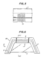
- Fig. 6 is a plan view of the mold;
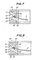
- Figs. 7 and 8 are cross-sectional views taken along the lines C-C and D-D in Fig. 6;
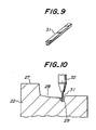
- Fig. 9 is a perspective view of a rod-like filling for forming the weir;
- Figs. 10 to 12 are cross-sectional views similar to Fig. 7, showing successive stages of the process step using the mold;
- Figs. 13a and 13b are perspective views of a pre-shaped frame body to be used in a method according to another embodiment of the present invention;
- Fig. 14 is a plan view of the pre-shaped frame body shown in Figs. 13a and 13b; and
- Figs. 15a and 15b are sectional views showing different regions of a window manufactured by the method according to still another embodiment of the present invention.
- There is shown in Figs. 1 and 2 an automobile window which is designated as a whole by
reference numeral 1. Thewindow 1 includes awindow plate 2 and awindow frame member 3 composed of a thermoplastic synthetic resin material which is integral with thewindow plate 2 and extends along the edges of thewindow plate 2. Theframe member 3 includes first andsecond lip sections web section 3c on its rear side. Thefirst lip section 3a is adapted to cover a gap between a shoulder portion of anautomobile body panel 4 and the edge of thewindow plate 2, so as to be engageable with the outer surface of thebody panel 4. Thesecond lip section 3b and theweb section 3c are arranged opposite to each other to accommodate the edge of thewindow plate 2 therebetween; thus, they are in engagement with the outer and rear surfaces of thewindow plate 2, respectively. - The
window frame member 3 includes side andupper regions window plate 2, respectively. In case of afront window 1 shown in Fig. 1, theside regions 5 of thewindow frame member 3 are provided withlongitudinal ridges 7. On the other hand, in case of an automobile rear window shown in Fig. 2, theridge 7 is provided on theupper region 6 of thewindow frame member 3. Thewindow plate 2 has an opaque printedlayer 8 along its periphery on its rear surface, and is mounted on aflange 4a of thebody panel 4 with an elongate andflexible dam element 9 and anadhesive material 10 therebetween, which are covered by the opaque printedlayer 8 so as not to be visible from outside. - In the
front window 1 shown in Fig. 1, eachridge 7 on theside region 5 of theframe member 3 serves to guide rain water on thewindow plate 2 to flow along the ridge and to prevent the water from flowing across theframe member 3, thereby to preserve the driver's sight through a neighbouring side window. Similarly, in case of therear window 1 shown in Fig. 2, theridge 7 on theupper region 6 of theframe member 3 is adapted to guide the rain water on the automobile roof panel to flow along the ridge and to prevent the water from flowing across theframe member 3, for preserving the driver's sight through the rear window. Furthermore, theupper region 6 of theframe member 3 in the front window and theside regions 5 of theframe member 3 in the rear window, which are not formed with theridge 7, makes it readily possible to realize a flush outer surface of the automobile body. - The automobile window shown in Fig. 1 or 2 can be manufactured by a method according to the present invention, of which a first embodiment will be explained below. First of all, as shown in Fig. 3, it is necessary to prepare a
window plate 2 and a pre-shaped frame body 11 substantially corresponding to theframe member 3. More particularly, thepre-shaped frame body 3 has a cross-section which is dimensionally somewhat smaller than, but geometrically similar to that of the region of theframe member 3 which is not formed with theridge 7. The pre-shaped frame body 11 is formed by extruding appropriate thermoplastic synthetic resin material having a relatively high dielectric loss, such as plasticized polyvinylchloride (PVC) resin, which contains a heat foamable agent. The extrusion is carried out under such a predetermined temperature condition that the heat foamable agent in the extruded thermoplastic synthetic resin material is maintained in a substantially unfoamed state or in a medium foamed state in which it has not reached an ultimately desired expansion degree. - The pre-shaped frame body 11 includes first and second lip sections 11a, 11b and a web section 11c which correspond to the first and
second lip sections web section 3c of theframe member 3, respectively, as well as an elongate dam section 11d which corresponds to thedam element 9 and is integrally connected to the web section 11c via a strip-like extension 11e. The pre-shaped frame body 11 further includes agroove 12 which is defined between the lip section 11b and the web section 11c. Thegroove 12 has bottom edges formed withslits 13 and the width of thegroove 12, i.e. the distance between the lip section 11b and the web section 11c, is slightly greater than the thickness of thewindow plate 2, so that the edge of thewindow plate 2 can be readily inserted into thegroove 12 by temporarily deflecting the lip and web sections 11b, 11c about theslits 13 to in cease the width of thegroove 12. - Advantageously, layers of a heat activation type synthetic resin material are formed on the inner surfaces of the
groove 12 in the pre-shaped frame body 11 synchronously with or after the extrusion thereof, which can be activated when heated above a predetermined temperature, to adhere the pre-shaped frame body 11 with thewindow plate 2. Alternatively, or additionally, the adhesive material layers may be formed on the front and rear surfaces of thewindow plate 2. The strip-like extension 11e connecting the dam section 11d with the web section 11c is preferably subjected to local removal of the material along itslongitudinal regions 14a to leave a desired number ofconnection bridges 14b. By this, theadhesive material 10 shown in Figs. 1 and 2 can be brought into direct contact with the rear surface of thewindow plate 2 through spaces between the neighbouringbridges 14b. - In the next step, as shown in Figs. 4a to 4c, the pre-shaped frame body 11 is temporarily secured to the edge of the
window plate 2 by an appropriate mechanical means. To this end, the pre-shaped frame body 11 may be cut into a predetermined length and then secured to the edge of thewindow plate 2 with the longitudinal ends of the neighbouring pre-shaped frame bodies 11 in abutment with each other. Alternatively, when the periphery of thewindow plate 2 has corner regions with a substantial radius of curvature, an elongate pre-shaped frame body 11 may be used to continuously cover the upper and side edges of thewindow plate 2 by bending the pre-shaped frame body 11 into the curvature of the corner regions of thewindow plate 2 without accompanying an undesirable deformation. When, on the other hand, the periphery of thewindow plate 2 has corner regions with a relatively small radius of curvature, the elongate pre-shaped frame body 11 may be used to continuously cover the edges of thewindow plate 2 by forming a series of substantially V-shaped notches 15 (Fig. 5) in those regions of the pre-shaped frame body 11 corresponding to the corner regions of thewindow plate 2, thereby to facilitate subsequent bending of the pre-shaped frame body 11 into the curvature of the corner regions of thewindow plate 2. - Thereafter, together with the side and upper edges of the
window plate 2, the pre-shaped frame body 11 is brought into the cavity of amold 20 including upper and lower mold halves 21, 22 and having a configuration corresponding to the peripheral contour of thewindow plate 2. As shown in Figs. 6 to 8, theupper mold half 21 is provided with anupper electrode 23 which is held in position by means of aholder plate 24. Similarly, thelower mold half 22 is provided with alower electrode 25 which is held in position by means of aholder plate 26. The twomold halves parting surface 27, to define amold cavity 28 therebetween. The mold halves 21, 22 are composed of a material with a relatively low dielectric loss, such as silicone resin, polyolefin-based resin or appropriate ceramic material. Theelectrodes frame member 3 on thewindow plate 2, and shaped to have a width which is greater than the horizontal width of thecavity 28, and spaced from thecavity 28 by as constant distance as possible at any location of the electrodes. Thecavity 28 of themold 20 includes side and upper regions connected with each other, which correspond to the side andupper regions window frame member 3, respectively. As for themold 20 adapted to be used in manufacturing the window shown in Fig. 1, each side region of thecavity 28 is formed with agroove 29 for forming theridge 7 therein. Theupper mold half 21 is further provided withcutter blades 30 which are adapted to form longitudinal slits in the pre-shaped frame body 11 corresponding to the eventual local removal of its material along thelongitudinal regions 14a of the strip-like extension 11e, thereby to leave the connection bridges 14b between the web and dam sections 11c, 11d. - Before bringing the pre-shaped frame body 11 into the
cavity 28 of themold 20, as shown in Fig. 9, a filling 31 corresponding to theridge 7 is arranged in eachgroove 29 of themold cavity 28, which preferably consists of a material containing a foamable agent, like the material of the pre-shaped frame body 11. The filling 31 may be an elongate rod-like body consisting preferably of a thermoplastic synthetic resin material which is same as that of the pre-shaped frame body 11, or which at least exhibits a sufficient compatibility with the latter. When, however, the material of the rod-like body 31 does not exhibit a sufficient compatibility, the rod-like body 31 may be applied with a layer of heat-activation type adhesive material on its surface which is to be opposed to the pre-shaped frame body 11. Also, as shown in Fig. 10, the filling 31 may be in the form of plastic sol or powder discharged from anapplicator 32. - After the filling 31 has been arranged in each
groove 29 of themold cavity 28 and the pre-shaped frame body 11 has subsequently been brought into thecavity 28 together with the relevant edges of thewindow plate 2, the twomold halves electrodes mold 20 of a material with a lower dielectric loss, or without accompanying softening of themold 20 or deformation of thecavity 28. By this, the pre-shaped frame body 11 is heated to a predetermined temperature above the softening temperature of the resin material and the foamable agent contained in the material of the pre-shaped body 11 is caused to evaporate, inducing the expansion of the entire pre-shaped frame body 11 in thecavity 28 so as to completely fill the inner space of the cavity. At the same time, the adhesive material layer between the pre-shaped frame body 11 and thewindow plate 2 is activated to integrally connect them with each other, to form awindow 1 including aframe member 3 which is integral with thewindow plate 2. Moreover, the pre-shaped frame body 11 heated above the softening temperature of the resin material is caused to adhere with the filling 31, as shown in Fig. 12, to form aframe member 3 withintegral ridges 7. When the filling 31 contains a foamable agent, the filling 31 also is caused to expand in themold cavity 28 to mitigate possible difference in appearance or color between theridge 7 and the remaining sections of theframe member 3. - After stopping the application of high frequency voltage and subjecting the
frame member 3 to cooling and solidification, the mold halves 21, 22 are disengaged from each other to take out thewindow 1 from themold 20. A completeautomobile front window 1 in its final form shown in Fig. 1 can be obtained after locally removing material from theframe member 3 along the longitudinal slits formed by theblades 30, leaving the connection bridges 14b between theweb section 3c and thedam element 9. - When manufacturing the automobile rear windows shown in Fig. 2, it is of course that the above-mentioned steps are to be carried out in essentially the same manner, using a mold which includes a cavity with side regions of the cross-section shown in Fig. 7 and an upper region of the cross-section shown in Fig. 8.
- Another embodiment of the method according to the prevent invention for manufacturing the automobile window shown in Fig. 1 or 2 will be explained below. This embodiment differs from the previous one in that, instead of forming the
ridges 7 by arranging a filling 31 in eachgroove 29 of themold cavity 28 and subsequently causing the filling 31 and the pre-shaped frame body 11 to adhere with each other, the pre-shaped frame body 11 is extruded into an initial, longitudinally constant cross-section as shown in Figs. 13a and 13b, including a continuous section 11f with the cross-section of theridge 7 on the second lip section 11b. - The pre-shaped frame body 11 is thereafter subjected to a local removal of the continuous section 11f. That is, in case of the automobile front window shown in Fig. 1, the continuous section 11f is removed along the region of the frame body 11 corresponding to the
upper region 6 of theframe member 3, while leaving the continuous section 11f along the regions of the frame body 11 corresponding to theside regions 5 of theframe member 3. Similarly, in case of the automobile rear window shown in Fig. 2, the continuous section 11f is removed along the regions of the frame body 11 corresponding to theside regions 5 of theframe member 3, while leaving the continuous section 11f along the region of the frame body 11 corresponding to theupper region 6 of theframe member 3. Fig. 14 shows the pre-shaped frame body 11 for an automobile front window, which has been subjected to the local removal of the continuous section 11f and formed with a series of substantially V-shapednotches 15 at regions corresponding to the corner regions of the window plate. - The above-mentioned step of local removal of the continuous section 11f from the pre-shaped frame body 11, and the step of temporarily securing the frame body 11 to the
window plate 2 may be carried out either simultaneously, or one after the other. It is of course that, when placing the pre-shaped frame body 11 in the mold cavity together with the relevant edges of thewindow plate 2, the remaining region of the continuous section 11f corresponding to theridge 7 is arranged in thegroove 29 within thecavity 28, like the filling 31 as shown in Fig. 11. - Except for the above-mentioned differences, the present embodiment is essentially to carry out the process steps as in the previous one.
- Still another embodiment of the method according to the present invention for manufacturing the automobile windows will be explained below. The window to be manufactured is illustrated in Figs. 15a and 15b, which differs from that shown in Figs. 1 and 2 in that it includes a
channel 41, instead of theridge 7, as means for guiding the flow of water on the window plate or roof panel. To this end, the pre-shaped frame body is extruded into the original, longitudinally constant cross-section essentially shown in Fig. 15a, including a longitudinal recess corresponding to thechannel 41. As shown in Fig. 15b, the recess is locally filled with asynthetic resin material 42 which may contain a foamable agent, along theupper region 6 in case of a front window, or along theside regions 5 in case of the rear window. Alternatively, the pre-shaped frame body may be extruded into the original, longitudinally constant cross-section essentially shown in Fig. 15b, including a relatively thick center section at a location corresponding to thechannel 41. The center section may be subjected to the local removal of the material to form the channel along theside regions 5 in case of a front window, or along theupper region 6 in case of the rear window. - It will be appreciated from the foregoing description that, according to the present invention, automobile windows can be manufactured without subjecting the window plate to a high injection pressure, so that the window plate can be prevented from undesirable tendency of damages and the method can be carried out using a mold of less complicated and less expensive arrangement. Moreover, the heat foamable agent in the thermoplastic synthetic resin material for the pre-shaped frame body is subjected to a substantially uniform expansion within the entire mold cavity, without accompanying local fluctuation of the expansion degree, so that it is possible to prevent the frame member from undesirable local deformation and to thereby manufacture improved automobile windows with a smooth outer surface and a satisfactory uniformity in the appearance or color.
- While the present invention has been described with reference to certain specific embodiments presented by way of examples only, those skilled in the art will readily appreciate that various modifications and/or alterations may be made without departing from the scope of the invention. For example, the guide portions in the form of a ridge or channel, which are arranged close to the window plate in the above-mentioned embodiments, may be formed at a location which is somewhat remote from the window plate and in the vicinity of the automobile body panel.
Claims (9)
preparing the guide portion separately from the pre-shaped frame body, prior to said high frequency voltage application step (E); and
causing the guide portion to adhere with the pre-shaped frame body, during said high frequency voltage application step (E).
forming said pre-shaped frame body with a constant cross-section including cross-sectional portion corresponding to said guide portion; and
removing material from said pre-shaped body at least locally over a predetermined length, corresponding to regions of the frame member without the guide portion, prior to said step (D) of placing the pre-shaped frame body in said mold.
Applications Claiming Priority (4)
| Application Number | Priority Date | Filing Date | Title |
|---|---|---|---|
| JP28433688A JPH02128917A (en) | 1988-11-10 | 1988-11-10 | Manufacture of window having synthetic resin frame |
| JP284336/88 | 1988-11-10 | ||
| JP284335/88 | 1988-11-10 | ||
| JP28433588A JPH02128916A (en) | 1988-11-10 | 1988-11-10 | Manufacture of window having synthetic resin frame |
Publications (3)
| Publication Number | Publication Date |
|---|---|
| EP0368669A2 true EP0368669A2 (en) | 1990-05-16 |
| EP0368669A3 EP0368669A3 (en) | 1991-07-24 |
| EP0368669B1 EP0368669B1 (en) | 1994-09-07 |
Family
ID=26555429
Family Applications (1)
| Application Number | Title | Priority Date | Filing Date |
|---|---|---|---|
| EP89311645A Expired - Lifetime EP0368669B1 (en) | 1988-11-10 | 1989-11-10 | Method of manufacturing automobile windows |
Country Status (3)
| Country | Link |
|---|---|
| EP (1) | EP0368669B1 (en) |
| CA (1) | CA2002768C (en) |
| DE (1) | DE68918050T2 (en) |
Cited By (9)
| Publication number | Priority date | Publication date | Assignee | Title |
|---|---|---|---|---|
| DE9012288U1 (en) * | 1990-08-27 | 1991-09-19 | Siv Deutschland Gmbh, 6000 Frankfurt, De | |
| EP0458662A2 (en) * | 1990-05-18 | 1991-11-27 | Sonoco Products Company | Plastic chime overlay for fibre drum |
| EP0485639A1 (en) * | 1990-11-10 | 1992-05-20 | Kuo-Nan Yang | EVA insole manufacturing process |
| EP0493809A1 (en) * | 1990-12-29 | 1992-07-08 | Asahi Glass Company Ltd. | A method of making a window glass with a synthetic resin frame |
| EP0577195A1 (en) * | 1992-07-01 | 1994-01-05 | ELELYS S.p.A. | Mould for moulding plastic materials by applying an electromagnetic field |
| US6106931A (en) * | 1990-12-27 | 2000-08-22 | Tokai Kogyo Kabushiki Kaisha | Panel unit |
| WO2002066277A3 (en) * | 2001-02-15 | 2002-10-31 | Ct Luxembourgeois Rech Verre | Method of applying extruded profile to corners of a window glazing |
| FR2947498A1 (en) * | 2009-07-03 | 2011-01-07 | Peugeot Citroen Automobiles Sa | Cover for window post of windscreen of motor vehicle, has gutter permitting discharge of swept water on windscreen through windscreen wiper, and exterior skin in flush contact with windscreen |
| FR2949101A1 (en) * | 2009-08-11 | 2011-02-18 | Peugeot Citroen Automobiles Sa | FRONT PART OF MOTOR VEHICLE. |
Families Citing this family (2)
| Publication number | Priority date | Publication date | Assignee | Title |
|---|---|---|---|---|
| DE102019126860A1 (en) * | 2019-10-07 | 2021-04-08 | Webasto SE | Lid for closing an opening in a vehicle body |
| CN110815899B (en) * | 2019-10-10 | 2022-01-07 | 中国直升机设计研究所 | Helicopter blade embedded box-shaped device and forming method thereof |
Citations (5)
| Publication number | Priority date | Publication date | Assignee | Title |
|---|---|---|---|---|
| GB733623A (en) * | 1952-04-04 | 1955-07-13 | Rubber Improvement Ltd | Improvements in or relating to edge-moulding |
| DE3403518A1 (en) * | 1984-02-02 | 1985-08-14 | Daimler-Benz Ag, 7000 Stuttgart | Design of a drip moulding of a motor vehicle |
| US4757659A (en) * | 1986-12-04 | 1988-07-19 | Tokiwa Chemical Industries Co., Ltd. | Front glass mouldings |
| DE3707481A1 (en) * | 1987-03-09 | 1988-09-22 | Heinz Schirmacher Gmbh | Foot mat made of fibrous material |
| EP0325828A1 (en) * | 1988-01-29 | 1989-08-02 | Hashimoto Forming Industry Co Ltd | Method of producing molding members |
-
1989
- 1989-11-10 CA CA002002768A patent/CA2002768C/en not_active Expired - Fee Related
- 1989-11-10 EP EP89311645A patent/EP0368669B1/en not_active Expired - Lifetime
- 1989-11-10 DE DE68918050T patent/DE68918050T2/en not_active Expired - Fee Related
Patent Citations (5)
| Publication number | Priority date | Publication date | Assignee | Title |
|---|---|---|---|---|
| GB733623A (en) * | 1952-04-04 | 1955-07-13 | Rubber Improvement Ltd | Improvements in or relating to edge-moulding |
| DE3403518A1 (en) * | 1984-02-02 | 1985-08-14 | Daimler-Benz Ag, 7000 Stuttgart | Design of a drip moulding of a motor vehicle |
| US4757659A (en) * | 1986-12-04 | 1988-07-19 | Tokiwa Chemical Industries Co., Ltd. | Front glass mouldings |
| DE3707481A1 (en) * | 1987-03-09 | 1988-09-22 | Heinz Schirmacher Gmbh | Foot mat made of fibrous material |
| EP0325828A1 (en) * | 1988-01-29 | 1989-08-02 | Hashimoto Forming Industry Co Ltd | Method of producing molding members |
Non-Patent Citations (2)
| Title |
|---|
| PATENT ABSTRACTS OF JAPAN, vol. 12, no. 126 (M-687)[2973], 19th April 1988; & JP-A-62 251 229 (TOKAI KOGYO K.K.) 02-11-1987 * |
| PATENT ABSTRACTS OF JAPAN, vol. 13, no. 122 (M-807)[3470], 27th March 1989; & JP-A-63 297 010 (HASHIMOTO FORMING CO., LTD) 05-12-1988 * |
Cited By (15)
| Publication number | Priority date | Publication date | Assignee | Title |
|---|---|---|---|---|
| EP0458662A2 (en) * | 1990-05-18 | 1991-11-27 | Sonoco Products Company | Plastic chime overlay for fibre drum |
| EP0458662A3 (en) * | 1990-05-18 | 1992-04-22 | Sonoco Products Company | Plastic chime overlay for fibre drum |
| DE9012288U1 (en) * | 1990-08-27 | 1991-09-19 | Siv Deutschland Gmbh, 6000 Frankfurt, De | |
| EP0485639A1 (en) * | 1990-11-10 | 1992-05-20 | Kuo-Nan Yang | EVA insole manufacturing process |
| US6106931A (en) * | 1990-12-27 | 2000-08-22 | Tokai Kogyo Kabushiki Kaisha | Panel unit |
| US6287406B1 (en) | 1990-12-27 | 2001-09-11 | Tokai Kogyo Kabushiki Kaisha | Methods for making window panel units having in situ extruded frames |
| US6787085B2 (en) | 1990-12-27 | 2004-09-07 | Tokai Kogyo Kabushiki Kaisha | Method for making window panel units having in situ extruded frames |
| US6803001B2 (en) | 1990-12-27 | 2004-10-12 | Tokai Kogyo Kabushiki Kaisha | Method for making window panel units having in situ extruded frames |
| EP0493809A1 (en) * | 1990-12-29 | 1992-07-08 | Asahi Glass Company Ltd. | A method of making a window glass with a synthetic resin frame |
| EP0577195A1 (en) * | 1992-07-01 | 1994-01-05 | ELELYS S.p.A. | Mould for moulding plastic materials by applying an electromagnetic field |
| WO2002066277A3 (en) * | 2001-02-15 | 2002-10-31 | Ct Luxembourgeois Rech Verre | Method of applying extruded profile to corners of a window glazing |
| US6513854B2 (en) | 2001-02-15 | 2003-02-04 | Centre Luxembourgeois De Recherches Pour Le Verre Et La Ceramique S.A. (C.R.V.C.) | Method of applying extruded profile to corners of a window glazing |
| FR2947498A1 (en) * | 2009-07-03 | 2011-01-07 | Peugeot Citroen Automobiles Sa | Cover for window post of windscreen of motor vehicle, has gutter permitting discharge of swept water on windscreen through windscreen wiper, and exterior skin in flush contact with windscreen |
| FR2949101A1 (en) * | 2009-08-11 | 2011-02-18 | Peugeot Citroen Automobiles Sa | FRONT PART OF MOTOR VEHICLE. |
| WO2011018570A3 (en) * | 2009-08-11 | 2011-04-21 | Peugeot Citroën Automobiles SA | Front end of a motor vehicle |
Also Published As
| Publication number | Publication date |
|---|---|
| EP0368669B1 (en) | 1994-09-07 |
| CA2002768C (en) | 1997-10-07 |
| DE68918050T2 (en) | 1995-02-23 |
| DE68918050D1 (en) | 1994-10-13 |
| CA2002768A1 (en) | 1990-05-10 |
| EP0368669A3 (en) | 1991-07-24 |
Similar Documents
| Publication | Publication Date | Title |
|---|---|---|
| US5197243A (en) | Window for automobiles or the like, and method of manufacturing the same | |
| US4778550A (en) | Method for developing a point of one end of an extruded plastic vehicle molding | |
| KR0183983B1 (en) | Method of making a spacer for a windshield bracket | |
| EP0368669B1 (en) | Method of manufacturing automobile windows | |
| EP0325828B1 (en) | Method of producing molding members | |
| US5028460A (en) | Molding member and method of producing same | |
| FI103493B (en) | Method of improving and / or renewing a profile extruded on a glass pane | |
| ES277280U (en) | Method and apparatus for changing the inclination or orientation of a longitudinal tab of an extruded weather strip for motor vehicles during its extrusion and weather strip thus obtained. | |
| GB2235152A (en) | Improvements in and relating to vehicle trim strips having remoulded ends and methods and apparatus for forming them | |
| US5435865A (en) | Process for manufacturing an automotive trim piece having a polymeric skin mounted to a substrate | |
| US5494630A (en) | Method of forming molding end | |
| JPH085092B2 (en) | Weather strip manufacturing method | |
| EP0368441B1 (en) | Trim moulding for vehicles | |
| US6223497B1 (en) | Windows for automobiles and the like | |
| EP0371773A2 (en) | Windows for automobiles or the like, and method of manufacturing the same | |
| JP4104703B2 (en) | Mold for post-molding a strip with a specific cross-section that is extruded on an object | |
| JPH09123213A (en) | Manufacture of windowpane equipped with profile frame of elastomer | |
| EP0329048A1 (en) | Guiding and retention gasket for sliding and retracting windows, particularly for motor vehicles, and process therefor | |
| JP2596096B2 (en) | Window molding and manufacturing method thereof | |
| JPS638021A (en) | Manufacture of window moulding | |
| JP2531218B2 (en) | Vehicle window manufacturing method | |
| JP2580890B2 (en) | Patterned connection method for extruded bodies with different stiffness | |
| JPH1170544A (en) | Manufacture of weatherstrip for automobile | |
| JP3186497B2 (en) | Automotive weather strip and method of manufacturing the same | |
| JPH02128916A (en) | Manufacture of window having synthetic resin frame |
Legal Events
| Date | Code | Title | Description |
|---|---|---|---|
| PUAI | Public reference made under article 153(3) epc to a published international application that has entered the european phase |
Free format text: ORIGINAL CODE: 0009012 |
|
| AK | Designated contracting states |
Kind code of ref document: A2 Designated state(s): DE FR GB IT |
|
| PUAL | Search report despatched |
Free format text: ORIGINAL CODE: 0009013 |
|
| AK | Designated contracting states |
Kind code of ref document: A3 Designated state(s): DE FR GB IT |
|
| 17P | Request for examination filed |
Effective date: 19911106 |
|
| 17Q | First examination report despatched |
Effective date: 19921006 |
|
| GRAA | (expected) grant |
Free format text: ORIGINAL CODE: 0009210 |
|
| AK | Designated contracting states |
Kind code of ref document: B1 Designated state(s): DE FR GB IT |
|
| REF | Corresponds to: |
Ref document number: 68918050 Country of ref document: DE Date of ref document: 19941013 |
|
| ITF | It: translation for a ep patent filed |
Owner name: PROPRIA PROTEZIONE PROPR. IND. |
|
| ET | Fr: translation filed | ||
| PLBE | No opposition filed within time limit |
Free format text: ORIGINAL CODE: 0009261 |
|
| STAA | Information on the status of an ep patent application or granted ep patent |
Free format text: STATUS: NO OPPOSITION FILED WITHIN TIME LIMIT |
|
| 26N | No opposition filed | ||
| PGFP | Annual fee paid to national office [announced via postgrant information from national office to epo] |
Ref country code: GB Payment date: 19961101 Year of fee payment: 8 |
|
| PGFP | Annual fee paid to national office [announced via postgrant information from national office to epo] |
Ref country code: FR Payment date: 19961111 Year of fee payment: 8 |
|
| PGFP | Annual fee paid to national office [announced via postgrant information from national office to epo] |
Ref country code: DE Payment date: 19961115 Year of fee payment: 8 |
|
| PG25 | Lapsed in a contracting state [announced via postgrant information from national office to epo] |
Ref country code: GB Free format text: LAPSE BECAUSE OF NON-PAYMENT OF DUE FEES Effective date: 19971110 |
|
| PG25 | Lapsed in a contracting state [announced via postgrant information from national office to epo] |
Ref country code: FR Free format text: THE PATENT HAS BEEN ANNULLED BY A DECISION OF A NATIONAL AUTHORITY Effective date: 19971130 |
|
| GBPC | Gb: european patent ceased through non-payment of renewal fee |
Effective date: 19971110 |
|
| PG25 | Lapsed in a contracting state [announced via postgrant information from national office to epo] |
Ref country code: DE Free format text: LAPSE BECAUSE OF NON-PAYMENT OF DUE FEES Effective date: 19980801 |
|
| REG | Reference to a national code |
Ref country code: FR Ref legal event code: ST |
|
| PG25 | Lapsed in a contracting state [announced via postgrant information from national office to epo] |
Ref country code: IT Free format text: LAPSE BECAUSE OF NON-PAYMENT OF DUE FEES Effective date: 20051110 |