EP0368460A1 - Coding apparatus - Google Patents
Coding apparatus Download PDFInfo
- Publication number
- EP0368460A1 EP0368460A1 EP89309707A EP89309707A EP0368460A1 EP 0368460 A1 EP0368460 A1 EP 0368460A1 EP 89309707 A EP89309707 A EP 89309707A EP 89309707 A EP89309707 A EP 89309707A EP 0368460 A1 EP0368460 A1 EP 0368460A1
- Authority
- EP
- European Patent Office
- Prior art keywords
- picture element
- value
- video data
- values
- decoded
- Prior art date
- Legal status (The legal status is an assumption and is not a legal conclusion. Google has not performed a legal analysis and makes no representation as to the accuracy of the status listed.)
- Granted
Links
Images


Classifications
-
- H—ELECTRICITY
- H04—ELECTRIC COMMUNICATION TECHNIQUE
- H04N—PICTORIAL COMMUNICATION, e.g. TELEVISION
- H04N19/00—Methods or arrangements for coding, decoding, compressing or decompressing digital video signals
- H04N19/90—Methods or arrangements for coding, decoding, compressing or decompressing digital video signals using coding techniques not provided for in groups H04N19/10-H04N19/85, e.g. fractals
- H04N19/98—Adaptive-dynamic-range coding [ADRC]
-
- H—ELECTRICITY
- H04—ELECTRIC COMMUNICATION TECHNIQUE
- H04N—PICTORIAL COMMUNICATION, e.g. TELEVISION
- H04N19/00—Methods or arrangements for coding, decoding, compressing or decompressing digital video signals
- H04N19/50—Methods or arrangements for coding, decoding, compressing or decompressing digital video signals using predictive coding
- H04N19/593—Methods or arrangements for coding, decoding, compressing or decompressing digital video signals using predictive coding involving spatial prediction techniques
-
- H—ELECTRICITY
- H04—ELECTRIC COMMUNICATION TECHNIQUE
- H04N—PICTORIAL COMMUNICATION, e.g. TELEVISION
- H04N19/00—Methods or arrangements for coding, decoding, compressing or decompressing digital video signals
- H04N19/30—Methods or arrangements for coding, decoding, compressing or decompressing digital video signals using hierarchical techniques, e.g. scalability
Definitions
- This invention relates to a highly efficient coding apparatus of image data for compressing and encoding the image data.
- JP,A Japanese patent laid open publication
- JP,A Japanese patent laid open publication
- JP,A Japanese patent laid open publication
- JP,A variable length encoding method in which the number of bits changes in accordance with the dynamic range so that the maximum distortion which occurs upon digitisation becomes constant.
- ADRCs The above encoding methods adapted to the dynamic range
- ADRCs relate to highly efficient coding methods whereby the number of bits per pixel is reduced by using the fact that images have a strong correlation in a small area (block) which is obtained by dividing one picture plane. That is, the difference between the minimum or maximum value in the block and the level of each pixel becomes smaller than the original level and the difference can be digitised into a number of bits which is smaller than the number of original bits.
- the present invention can be applied to the digitisation of the level which has been standardised by the minimum or maximum value in the foregoing ADRC processing.
- this invention is not limited to ADRC processing but can be also applied to a digitising circuit for expressing a digital image signal by a predetermined number of bits in a manner similar to ADRC processing.
- the dynamic range DR for a block as the difference between the maximum value MAX and minimum value MIN is uniformly divided into four level ranges and the value of the pixel from which the minimum value MIN was eliminated is expressed by the digitisation code of two bits respectively corresponding to the level ranges.
- one of central decoding representative levels I0 to I3 in each level range is decoded from the dynamic range DR and the digitisation code, and the minimum value MIN is added to the decoded value, so that the pixel data in the block is reconstructed.
- Figure 2 shows an example of the digitisation in the ADRC.
- Figure 2 shows an example of a one-dimensional ADRC in which one block is constructed by six pixels which are continuous in the horizontal direction. Data indicated by ⁇ denotes the true values of the pixels in the block. Therefore, the digitisation has a horizontal change indicated by a solid line 41.
- reconstruction levels indicated by x are obtained on the decoding side and a change in signal shown by a broken line 42 occurs in the reconstructed image.
- the level of the original pixel is substituted by the nearest decoding representative level in order to minimise the digitisation error and to improve the S/N ratio.
- the original smooth horizontal change 41 results in the rough change 42 after the reconstruction.
- Visually conspicuous noises are generated in the reconstructed image. These noises are such that snow noises occurring in the television image received from a weak electric field are made fine and show up as the jitter-like noises. The occurrence of such a problem is based on the fact that when human beings recognise an image, they are sensitive to the differentiating characteristic of the image.
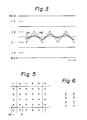
- Figure 3 shows another example of the digitisation in the ADRC.
- Figure 3 shows a time change of pixels at the positions which respectively belong to six frames which are continuous in the time direction and spatially correspond to those frames.
- each block in which the six pixels are included has the equal maximum value MAX and the equal minimum value MIN.
- the data shown by ⁇ denotes the true values of the pixels. Therefore, there is a change in the time direction shown by a solid line 141.
- the reconstruction levels shown by x are obtained on the decoding side and a change in signal shown by a broken line 142 occurs in the reconstructed image.
- the original smooth change 141 in the time direction results in the rough change 142 after the reconstruction.
- the visually conspicuous noises are generated in the reconstructed image like an example shown in figure 2.
- an object of the present invention to provide a highly efficient coding apparatus which can preserve spatial change in the original image signal even if quantitative errors increase and visually improve the picture quality of the reconstructed image.
- a highly efficient coding apparatus for coding original digital video data comprising n bits for each picture element to provide compressed video data having a number of bits less than n for each picture element, comprising: first detecting means for detecting a first difference between an original digital value of a first picture element to be encoded and an original digital value of a spatially adjacent picture element of said first picture element, first local decoding means for decoding encoded video data of said spatially adjacent picture element to generate a first decoded value, and generating means for generating compressed encoded video data of said first picture element wherein the difference between the decoded value of said compressed encoded video data and said first decoded value is closest to said first difference.
- the invention also provides a highly efficient coding apparatus for coding original digital video data comprising n bits for each picture element to provide compressed video data having a number of bits less than n for each picture element, comprising: first detecting means for detecting a first difference between an original value of a first picture element to be encoded and an original digital value of a time-adjacent and spatially identical picture element of said first picture element, first local decoding means for decoding encoded video data of said time-adjacent and spatially identical picture element to generate a first decoded value, and generating means for generating compressed encoded video data of said first picture element wherein the difference between the decoded value of said compressed encoded video data and said first decoded value is closest to said first difference.
- the invention further provides a highly efficient coding apparatus for coding original digital video data comprising n bits for each picture element to provide compressed video data having a number of bits less than n for each picture element, comprising: first local decoding means for decoding all compressed code data and for generating decoded values for a first picture element to be encoded, first detecting means for detecting first differences between an original digital value of said first picture element and said each of said decoded values, second detecting means for detecting second differences between a difference value of the original digital value of said first picture element and an original digital value of a spatially adjacent picture element of said first element and difference values of said decoded values and a decoded value of an encoded data of said spatially adjacent picture element, third detecting means for detecting third differences between a difference value of the original digital value of said first picture element and an original digital value of timely adjacent and spatially identical picture element of said first element and difference values of said decoded values and a decoded value of an encoded data of said timely adjacent and spatially identical picture element,
- the invention can provide a highly efficient coding apparatus which can preserve time dependent change in the original image signal and visually improve the picture quality of the reconstructed image and which is preferably adapted to the characteristics such as pattern, movement amount, and the like of an image and the picture quality of the reconstructed image is visually improved.
- a digital video signal in which, for instance, one pixel (one sample) is digitised to eight bits is supplied to an input terminal shown by reference numeral 1.
- the order of the data of the input digital video signal is changed from the scanning order to the order of blocks by a block segmentation circuit 2.
- N-1 denotes a preceding block and N indicates an objective block to be encoded.
- the data of the pixel at the top left-hand corner of the block N is first transmitted.
- the data of three pixels arranged in the horizontal direction within the block N are then transmitted.
- the data of the second, third and fourth rows within the block are serially transmitted.
- An output signal of the block segmentation circuit 2 is supplied to a maximum value and minimum value detecting circuit 3.
- the maximum value MAX and the minimum value MIN of the pixels included in each blocks are detected, respectively.
- the maximum value MAX and the minimum value MIN are supplied to a subtracting circuit 4 and a dynamic range DR as a difference between them is calculated.
- the dynamic range DR and the minimum value MIN are supplied to a frame segmentation circuit 5.
- the dynamic range DR, the minimum value MIN, and a digitisation code DT which will be explained hereinafter, are converted into a signal format of a frame construction and are subjected to an error correction encoding process (CRC, parity, etc) as necessary. Transmission data is obtained to an output terminal 6 of the frame segmentation circuit 5.
- the output signal of the block segmentation circuit 2 is supplied to one of the input terminals of a selector 10 through delay circuits 7, 8 and 9.
- the output signal of the delay circuit 8 is supplied to the other input terminals of the selector 10.
- the delay amount DL1 of the delay circuit 7 corresponds to the time necessary to detect the maximum value and the minimum value.
- the delay amount DL2 of the delay circuit 8 corresponds to the interval in the horizontal direction between pixels, that is, one sampling period. Therefore, the difference ⁇ r in the horizontal direction between the data of the pixel which is preceding by one sample and the data of the objective pixel to be encoded is generated from the subtracting circuit 11.
- the selector 10 selects the data of the pixel at the right edge in the preceding block from the delay circuit 9.
- a delay amount DL3 of the delay circuit 9 is set to (one block period - three sampling periods).
- the selector 10 is controlled by a selection signal from a selection signal generating circuit 12.
- Clock signals (a sampling clock and a block clock) from a terminal 13 are supplied to the selection signal generating circuit 12 and the selection signal to control the selector 10 as mentioned above is formed.
- the difference ⁇ r between the true values of the image data from the subtracting circuit 11 is supplied to subtracting circuits 14, 15, 16 and 17.
- the output signals ⁇ 0, ⁇ 1, ⁇ 2 and ⁇ 3 of the subtracting circuits 14-17 are supplied to a minimum value detecting circuit 18 and the minimum output signal is detected.
- the detection signal of the minimum value detecting circuit 18 is supplied to a code selecting circuit 19 and the digitisation code DT of two bits is generated from the code selection circuit 19.
- the digitisation code DT is transmitted through the frame segmentation circuit 5.
- the code selecting circuit 19 one of the two-bit digitisation codes (00), (01), (10) and (11) corresponding to the decoding representative levels I0, I1, I2 and I3 respectively is selected.
- the selecting operation of the code selecting circuit 19 is as follows.
- Signals ⁇ 0, ⁇ 1, ⁇ 2 and ⁇ 3 are supplied from subtracting circuits 20, 21, 22 and 23 to the subtracting circuits 14-17.
- the signals ⁇ 0- ⁇ 3 corresponding to the differences between the decoding level (X0) of the pixel preceding the objective pixel and the four decoding representative levels and indicate the predictive change amount respectively.
- the subtracting circuits 14-17 and the minimum value detecting circuit 18 detect among the signals ⁇ 0- ⁇ 3, the one closest to the difference ⁇ r in the horizontal direction of the true value of the image data.
- the digitisation code DT corresponding to the decoding representative level which generates the change closest to the signal change in the horizontal direction of the original image signal is selected with respect to the objective pixel.
- Decoding representative levels (MIN + I0), (MIN + I1), (MIN + I2) and (MIN + I3) formed by local decoders 28, 29, 30 and 31 are supplied to the subtracting circuits 20-23.
- the dynamic range DR and the minimum value MIN are supplied to the local decoders 28-31.
- two-bit digitisation codes (00), (01), (10) and (11) are supplied from terminals 24, 25, 26 and 27, respectively.
- the local decoders 28-31 and 32 comprise ROMs to which the dynamic range DR and digitisation code DT are supplied as addresses.
- the minimum value MIN is added to the data read out of the ROMs, which thus act as look-up tables.
- the decoding level X0 of the pixel preceding the objective pixel is formed by the local decoder 32, delay circuits 33, 34 and 35, and a selector 35.
- a digitisation code DT from the code selecting circuit 19 is supplied to the local decoder 32.
- a decoding level of the objective pixel is generated from the local decoder 32.
- the decoding level is supplied to one input terminal of the selector 35 through the delay circuit 33 having the delay amount DL2 of one sampling period.
- An output signal of the delay circuit 33 is supplied to the outer input terminal of the selector 35 through the delay circuit 34 having the delay amount DL3 of (one block period - three sampling periods).
- the selector 35 is controlled by the selection signal from the selection signal generating circuit 12 in a manner similar to the foregoing selector 10.
- the delay circuits 33 and 34 and selector 35 generate the decoding level X0 of the preceding pixel x0 of the objective pixel x1 in a manner similar to the foregoing delay circuits 8 and 9 and selector 10.
- the decoding level is supplied to the subtracting circuits 20-23. Therefore, the signals ⁇ 0 to ⁇ 3 which are respectively generated from the subtracting circuits 20-23 correspond to the predictive differences between the four decoding representative levels and the decoding level X0 of the preceding pixel as will be shown below.
- the code selecting circuit 19 Since the minimum one of ⁇ 0- ⁇ 3 is detected by the minimum value detecting circuit 18, the digitisation code of which the predictive change amount is closest to the true value of the change amount ⁇ r is selected by the code selecting circuit 19.
- ⁇ r (3x - a - b - c)
- ⁇ i (3Ii -A - B - C)
- A, B and C denote levels which are obtained by decoding the digitisation codes derived with respect to a, b and c respectively.
- the digitisation code signal generating ⁇ i which is closest to ⁇ r is selected.
- the digitisation code signal generating ⁇ i which is closest to ⁇ r is selected.
- the present invention can be applied to a digitising circuit in other highly efficient coding such as ADRC of a variable length, ADRC of a three-dimensional block, etc.
- the data of the respective pixels are digitised to have the decoding representative value shown by ⁇ , and therefore the change of the reconstructed image results in a smooth change similarly to the original signal as shown by a broken line 43.
- the spatial change of the original image signal can be preserved, so that the generation of the visually conspicuous noises in the reconstructed image can be prevented.
- a digital video signal in which, for instance, one pixel (one sample) is digitised into eight bits is supplied to an input terminal shown by reference numeral 101.
- the order of the data of the input digital video signal is changed from the scanning order to the order of blocks by a block segmentation circuit 2. Since the maximum value and minimum value detecting circuit 103, subtracting circuit 104 and frame segmentation circuit 105 having output terminal 106 have the same construction as the circuits 3, 4 and 5 in figure 4, the detailed description of those is omitted for simplicity.
- the output signal of the block segmentation circuit 102 is supplied to one of the input terminals of a subtracting circuit 109 through delay circuits 107 and 108.
- the delay amount DL1 of the delay circuit 107 corresponds to the time necessary to detect the maximum and minimum value.
- the output signal of the delay circuit 107 is supplied to the other input terminal of the subtracting circuit 109.
- the difference ⁇ t between the true values of the image data from the subtracting circuit 109 is supplied to subtracting circuits 110, 111, 112 and 113.
- the output signals r0, r1, r2 and r3 of the subtracting circuits 110-113 are supplied to a minimum value detecting circuit 114 and the minimum output signal is detected.
- the detection signal of the minimum value detecting circuit 114 is supplied to a code selecting circuit 115 and a two-bit digitisation code DT is generated from the code selecting circuit 115.
- the digitisation code DT is transmitted through the frame segmentation circuit 105.
- the code selecting circuit 115 one of the two-bit digitisation codes (00), (01), (10) and (11) corresponding to the decoding representative levels I0, I1, I2 and I3 is selected.
- the selecting operation of the code selecting circuit 115 is as follows.
- Signals ⁇ 00, ⁇ 01, ⁇ 02 and ⁇ 03 are supplied from subtracting circuits 116, 117, 118 and 119 to the subtracting circuits 110-113.
- the signals ⁇ 00- ⁇ 03 corresponding to the differences between the decoding level (X10) of the reference pixel and the four decoding representative levels and indicate the predictive change amount respectively.
- the subtracting circuits 110-113 and the minimum value detecting circuit 114 detect among the signals ⁇ 00- ⁇ 03, the one closest to the difference ⁇ t in the time direction of the true value of the image data. In other words, a digitisation code DT corresponding to the decoding representative level which generates the change closest to the signal change in one frame period of the original image signal is selected with respect to the objective pixel.
- decoding representative levels (MIN + I0), (MIN + I1), (MIN + I2) and (MIN + I3) formed by the local decoders 124, 125, 126 and 127 are supplied.
- the dynamic range DR and the minimum value MIN are supplied to the local decoders 124-127.
- two-bit digitisation codes (00), (01), (10) and (11) are supplied from terminals 120, 121, 122 and 123, respectively.
- the local decoders 124-127 and 128 comprise ROMs to which the dynamic range DR and digitisation code DT are supplied as addresses.
- the minimum value MIN is added to the data read out of the ROMs.
- the decoding level X10 of the reference pixel is formed by a local decoder 128 and a delay circuits 129 having the delay amount DL2 of one frame period.
- the digitisation data DT from the code selecting circuit 115 is supplied to a local decoder 128.
- a decoding level of the objective pixel is generated from the local decoder 128.
- the decoding level x10 of the reference pixel is obtained.
- the decoding level is supplied to the subtracting circuits 116-119. Therefore, the signals ⁇ 00 to ⁇ 03 which are respectively generated from the subtracting circuits 116-119 correspond to the predictive difference between the four decoding representative levels and the decoding level X10 of the preceding pixel as will be shown below.
- the code selecting circuit 115 Since the minimum one of r0-r3 is detected by the minimum value detecting circuit 114, the digitisation code of which the predictive change amount is closest to the true value of the change amount ⁇ t of the true value is selected by the code selecting circuit 115.
- time dependent change of the original image signal can be preserved so that the generation of the visually conspicuous noises in the reconstructed image can be prevented.
- the generation of the noises in the time direction cannot be prevented.
- the generation of the spatial noses cannot be prevented.
- the digitising system in which such signal changes are significant has a problem such that errors are accumulated.
- a highly efficient coding apparatus which can be adapted preferably to the characteristics such as pattern, movement amount of a picture, and the like of an image and which can improve the picture quality of the reconstructed image visually will be described hereinbelow with reference to figure 8.
- a digital video signal in which, for instance, one pixel (one sample) is digitised into eight bits is supplied to an input terminal shown by reference numeral 201.
- the order of the data of the input digital video signal is changed from the scanning order to the order of blocks by a block segmentation circuit 202.
- circuits 203, 204 and 206 have the same construction as the circuits 3, 4 and 5 in figure 4, the detailed description of those is omitted.
- the output signal of the block segmentation circuit 202 is supplied to input terminals 211, 221 and 231 of a distortion detecting circuit 208, an inner space change detecting circuit 209, and a time dependent change detecting circuit 210 through a delay circuit 207.
- the delay amount DL1 of the delay circuit 207 corresponds to the time necessary to detect the maximum and minimum values.
- the distortion detecting circuit 208 is the first arithmetic operating circuit for respectively arithmetically operating differences ⁇ 0, ⁇ 1, ⁇ 2 and ⁇ 3 between a true value x1 of the objective pixel and four decoding representative values corresponding to the number of bits.
- the decoding representative values are formed by local decoders 241, 242, 243 and 244. Digitisation codes (00), (01), (10) and (11) each consisting of two bits are supplied from terminals 245, 246, 247 and 248 to the local decoders 241 to 244, respectively.
- the dynamic range DR and the minimum value MIN are supplied to the local decoders 241 to 244.
- the distortion detecting circuit 208 has input terminals 212, 213, 214 and 215 to which the above decoding representative values are respectively supplied and output terminals 217, 218, 219 and 220 to which the output signals ⁇ 0 to ⁇ 3 are extracted.
- the inner space change detecting circuit 209 is the second arithmetic operating circuit for calculating a spatial first change amount ⁇ r from the true value of the objective pixel and the true value of a peripheral pixel which spatially locates in the periphery, for calculating spatial second change amounts ⁇ 0, ⁇ 1, ⁇ 2 and ⁇ 3 from the decoding value of the digitisation code of the peripheral pixel and the decoding representative values, and for calculating differences ⁇ 0, ⁇ 1, ⁇ 2 and ⁇ 3 between the first change amount ⁇ r and the second change amounts ⁇ 0 to ⁇ 3.
- the inner space change detecting circuit 209 has input terminals 222, 223, 224 and 225 to which the above decoding representative values are respectively supplied, an input terminal 226 to which the decoded value of the digitisation code DT is supplied, and output terminals 227, 228, 229 and 230 to which the differences ⁇ 0 to ⁇ 3 are extracted.
- the decoded value of the digitisation code DT is formed by a local decoder 257.
- the dynamic range DR, the minimum value MIN, and the digitisation code DT are supplied to the local decoder 257 and the level corresponding to the digitisation code Dt is reconstructed by the decoding of the ADRC.
- the local decoders 241, 244 and 257 comprise ROMs to which the dynamic range DR and digitisation code are supplied as addresses.
- the minimum value MIN is added to the data read out of the ROMs.
- the time dependent change detecting circuit 210 is the third arithmetic operating circuit for calculating a time dependent third change amount ⁇ t from the true value of the objective pixel and a true value of a reference pixel which is time precedent to the objective pixel and spatially corresponds thereto, for calculating time dependent fourth change amounts ⁇ 00, ⁇ 01, ⁇ 02 and ⁇ 03 from the decoded value of the digitisation code of the reference pixel and the decoding representative values, and for calculating differences r0, r1, r2 and r3 between the third change amount ⁇ t and the fourth change amounts ⁇ 00 to ⁇ 03.
- the time dependent change detecting circuit 220 has input terminals 232, 233, 234 and 235 to which the above decoding representative values are respectively supplied, an input terminal 236 to which the decoded value of the digitisation code is supplied, and output terminals 237, 238, 239 and 240 to which the output signals r0 to r3 are extracted.
- Respective output signals of the distortion detecting circuit 208, inner space change detecting circuit 209, and time dependent change detecting circuit 210 are synthesised by weighting adding circuits 251, 252, 253 and 254. That is, the differential signals with respect to each of the four decoding representative values are weighted and added.
- weighting coefficients w0 to w2 may be used as the weighting coefficients w0 to w2 and they are set in consideration of the characteristics of the input image or the like.
- the synthesised outputs ⁇ 1 to ⁇ 3 from the weighting adding circuits 251 to 254 are supplied to a minimum value detecting circuit 255.
- the minimum value detecting circuit 255 generates a detection signal indicative of the minimum one of the synthesised outputs ⁇ 1 to ⁇ 3.
- the detection signal is supplied to a code selecting circuit 256.
- the digitisation code DT of two bits which is specified by the detection signal is generated from the code selecting circuit 256.
- the digitisation code DT is transmitted through the frame segmentation circuit 205. That is, in the code selecting circuit 256, one of the two-bit digitisation codes (00), (01), (10) and (11) corresponding to the decoding representative levels I0, I1, I2 and I3 is selected.
- the selecting operation of the code selecting circuit 256 is as follows.
- the reception data is supplied to a frame desegmentation circuit and the dynamic range DR, the minimum value MIN, and the digitisation code DT are separated by the frame desegmentation circuit.
- the dynamic range DR and the digitisation code DT are supplied to the ROMs.
- the decoding level after the minimum value was eliminated is formed.
- the minimum value MIN is added to the decoding level. Further, the reconstruction levels obtained as the results of the addition are changed to the original scanning order by a block separating circuit.
- the distortion detecting circuit 208 comprises subtracting circuits 261, 262, 263 and 264.
- the true value x1 of the objective pixel is commonly supplied from the input terminal 211 to the subtracting circuits 261 to 264, respectively.
- the decoding representative levels (MIN + I0), (MIN + I1), (MIN + I2) and (MIN _ I3) are supplied from the input terminals 212 to 215 to the subtracting circuits 261 to 264, respectively. Therefore, the following output signals ⁇ 0 to ⁇ 3 are obtained at the output terminals 217 to 220 of the subtracting circuits 261 to 264, respectively.
- the output signals ⁇ 0 to ⁇ 3 of the above distortion detecting circuit 208 indicate the differences between the true value x1 of the objective pixel and the decoding representative levels.
- the two-bit digitisation code corresponding to the minimum one of the ⁇ 0 to ⁇ 3 expresses x1 by the minimum distortion (the S/N ratio is best).
- the inner space change detecting circuit 209 has a construction corresponding to that shown in figure 4. Similarly the construction of the time dependent change detecting circuit 210 corresponds to that shown in figure 7. Therefore, the detailed description of these circuits 209 and 210 is omitted, respectively.
- the third embodiment is adapted to the characteristics such as pattern, movement amount, and the like of the original image signal and the S/N ratio can be improved.
- the spatial change or time dependent change of the original image signal can be preserved, so that the generation of visually conspicuous noises in the reconstructed image can be prevented.
Abstract

Description
- This invention relates to a highly efficient coding apparatus of image data for compressing and encoding the image data.
- Various kinds of encoding systems have been proposed for reducing the number of bits of each pixel or picture element (sample) of the digitised image data by using the correlation of image signals. The specification of our Japanese patent laid open publication (JP,A) number 144989/1986 discloses highly efficient coding apparatus in which the dynamic range is derived as a difference between the maximum value and minimum value of a plurality of pixels included in a two-dimensional block and the encoding process is adapted to the dynamic range so established. On the other hand, in the specification of Japanese patent laid open publication (JP,A) number 92626/1987, there has been proposed a highly efficient coding apparatus in which encoding adapted to the dynamic range is executed with respect to a three-dimensional block which is formed by pixels in a plurality of areas each belonging to a plurality of frames. Further, as disclosed in the specification of Japanese patent laid open publication (JP,A) number 128621/1985, there has been proposed a variable length encoding method in which the number of bits changes in accordance with the dynamic range so that the maximum distortion which occurs upon digitisation becomes constant.
- The above encoding methods adapted to the dynamic range (hereinafter, abbreviated to ADRCs) relate to highly efficient coding methods whereby the number of bits per pixel is reduced by using the fact that images have a strong correlation in a small area (block) which is obtained by dividing one picture plane. That is, the difference between the minimum or maximum value in the block and the level of each pixel becomes smaller than the original level and the difference can be digitised into a number of bits which is smaller than the number of original bits.
- The present invention can be applied to the digitisation of the level which has been standardised by the minimum or maximum value in the foregoing ADRC processing. However, this invention is not limited to ADRC processing but can be also applied to a digitising circuit for expressing a digital image signal by a predetermined number of bits in a manner similar to ADRC processing.
- As shown in figure 1 of the accompanying drawings, in the ADRC for performing the digitisation of two bits, the dynamic range DR for a block as the difference between the maximum value MAX and minimum value MIN is uniformly divided into four level ranges and the value of the pixel from which the minimum value MIN was eliminated is expressed by the digitisation code of two bits respectively corresponding to the level ranges. On the decoding side, one of central decoding representative levels I0 to I3 in each level range is decoded from the dynamic range DR and the digitisation code, and the minimum value MIN is added to the decoded value, so that the pixel data in the block is reconstructed.
- Figure 2 shows an example of the digitisation in the ADRC. Figure 2 shows an example of a one-dimensional ADRC in which one block is constructed by six pixels which are continuous in the horizontal direction. Data indicated by ○ denotes the true values of the pixels in the block. Therefore, the digitisation has a horizontal change indicated by a
solid line 41. In the case where the encoding was executed by two-bit ADRC, reconstruction levels indicated by x are obtained on the decoding side and a change in signal shown by abroken line 42 occurs in the reconstructed image. - In the conventional digitisation technique, the level of the original pixel is substituted by the nearest decoding representative level in order to minimise the digitisation error and to improve the S/N ratio. However, there is a case where a visually conspicuous deterioration occurs in the reconstructed image even if the image is quantitatively good. In the example shown in figure 2, the original smooth
horizontal change 41 results in therough change 42 after the reconstruction. Visually conspicuous noises are generated in the reconstructed image. These noises are such that snow noises occurring in the television image received from a weak electric field are made fine and show up as the jitter-like noises. The occurrence of such a problem is based on the fact that when human beings recognise an image, they are sensitive to the differentiating characteristic of the image. - Figure 3 shows another example of the digitisation in the ADRC. Figure 3 shows a time change of pixels at the positions which respectively belong to six frames which are continuous in the time direction and spatially correspond to those frames. For simplicity, it is assumed that each block in which the six pixels are included has the equal maximum value MAX and the equal minimum value MIN. The data shown by ○ denotes the true values of the pixels. Therefore, there is a change in the time direction shown by a
solid line 141. In the case where the encoding was executed by the ADRC of two bits, the reconstruction levels shown by x are obtained on the decoding side and a change in signal shown by abroken line 142 occurs in the reconstructed image. - In the example shown in figure 3, the original
smooth change 141 in the time direction results in therough change 142 after the reconstruction. The visually conspicuous noises are generated in the reconstructed image like an example shown in figure 2. - It is, therefore, an object of the present invention to provide a highly efficient coding apparatus which can preserve spatial change in the original image signal even if quantitative errors increase and visually improve the picture quality of the reconstructed image.
- According to the invention, there is provided a highly efficient coding apparatus for coding original digital video data comprising n bits for each picture element to provide compressed video data having a number of bits less than n for each picture element, comprising:
first detecting means for detecting a first difference between an original digital value of a first picture element to be encoded and an original digital value of a spatially adjacent picture element of said first picture element,
first local decoding means for decoding encoded video data of said spatially adjacent picture element to generate a first decoded value, and
generating means for generating compressed encoded video data of said first picture element wherein the difference between the decoded value of said compressed encoded video data and said first decoded value is closest to said first difference. - The invention also provides a highly efficient coding apparatus for coding original digital video data comprising n bits for each picture element to provide compressed video data having a number of bits less than n for each picture element, comprising:
first detecting means for detecting a first difference between an original value of a first picture element to be encoded and an original digital value of a time-adjacent and spatially identical picture element of said first picture element,
first local decoding means for decoding encoded video data of said time-adjacent and spatially identical picture element to generate a first decoded value, and
generating means for generating compressed encoded video data of said first picture element wherein the difference between the decoded value of said compressed encoded video data and said first decoded value is closest to said first difference. - The invention further provides a highly efficient coding apparatus for coding original digital video data comprising n bits for each picture element to provide compressed video data having a number of bits less than n for each picture element, comprising:
first local decoding means for decoding all compressed code data and for generating decoded values for a first picture element to be encoded,
first detecting means for detecting first differences between an original digital value of said first picture element and said each of said decoded values,
second detecting means for detecting second differences between a difference value of the original digital value of said first picture element and an original digital value of a spatially adjacent picture element of said first element and difference values of said decoded values and a decoded value of an encoded data of said spatially adjacent picture element,
third detecting means for detecting third differences between a difference value of the original digital value of said first picture element and an original digital value of timely adjacent and spatially identical picture element of said first element and difference values of said decoded values and a decoded value of an encoded data of said timely adjacent and spatially identical picture element,
weighting and adding means for multiplying first, second and third weighting coefficients to said first, second and third differences, respectively and for adding corresponding ones of the multiplied first, second and third differences together to generate added values,
minimum detecting means supplied with said added values and for detecting a minimum value thereof, and
code selecting means for selecting one of compressed code data corresponding to said minimum value. - As will become apparent from the following description, the invention can provide a highly efficient coding apparatus which can preserve time dependent change in the original image signal and visually improve the picture quality of the reconstructed image and which is preferably adapted to the characteristics such as pattern, movement amount, and the like of an image and the picture quality of the reconstructed image is visually improved.
- The invention will be further described by way of non-limitative example with reference to the accompanying drawings, in which:-
- Figure 1 is a schematic diagram for use in explanation of a principle of a digitisation in ADRC;
- Figures 2 and 3 are schematic diagrams for use in explanation of a characteristic of a conventional digitising circuit;
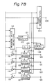
- Figure 4 is a block diagram showing a first embodiment of the present invention;
- Figures 5 and 6 are schematic diagrams for use in explanation of a first embodiment of the present invention;
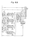
- Figure 7 is a block diagram showing a second embodiment of the present invention;
- Figure 8 is a block diagram showing a third embodiment of the present invention; and
- Figure 9 is a block diagram showing the details of a distortion detection circuit in the third embodiment of the resent invention shown in figure 8.
- A first embodiment of the present invention will be described hereinbelow with reference to the drawings.
- In figure 4, a digital video signal in which, for instance, one pixel (one sample) is digitised to eight bits is supplied to an input terminal shown by
reference numeral 1. The order of the data of the input digital video signal is changed from the scanning order to the order of blocks by ablock segmentation circuit 2. For instance, a picture plane of one frame is divided into small areas and (4 x 4 = 16 pixels) blocks are formed as shown in figure 5. In figure 5, N-1 denotes a preceding block and N indicates an objective block to be encoded. In the block, the data of the pixel at the top left-hand corner of the block N is first transmitted. The data of three pixels arranged in the horizontal direction within the block N are then transmitted. Similarly the data of the second, third and fourth rows within the block are serially transmitted. - An output signal of the
block segmentation circuit 2 is supplied to a maximum value and minimumvalue detecting circuit 3. The maximum value MAX and the minimum value MIN of the pixels included in each blocks are detected, respectively. The maximum value MAX and the minimum value MIN are supplied to asubtracting circuit 4 and a dynamic range DR as a difference between them is calculated. The dynamic range DR and the minimum value MIN are supplied to aframe segmentation circuit 5. In theframe segmentation circuit 5, the dynamic range DR, the minimum value MIN, and a digitisation code DT, which will be explained hereinafter, are converted into a signal format of a frame construction and are subjected to an error correction encoding process (CRC, parity, etc) as necessary. Transmission data is obtained to anoutput terminal 6 of theframe segmentation circuit 5. - The output signal of the
block segmentation circuit 2 is supplied to one of the input terminals of aselector 10 throughdelay circuits delay circuit 8 is supplied to the other input terminals of theselector 10. The output signal of thedelay circuit 7 and the output signal of theselector 10 are supplied to a subtractingcircuit 11, and the difference Δr in the horizontal direction of the original pixel data (true value) is calculated. Assuming that the true value of the objective pixel is set to x1 and the true value of the pixel which is preceding by one sampling period is set to x0, then Δr = x1 - x0. - The delay amount DL1 of the
delay circuit 7 corresponds to the time necessary to detect the maximum value and the minimum value. The delay amount DL2 of thedelay circuit 8 corresponds to the interval in the horizontal direction between pixels, that is, one sampling period. Therefore, the difference Δr in the horizontal direction between the data of the pixel which is preceding by one sample and the data of the objective pixel to be encoded is generated from the subtractingcircuit 11. - In the case of the pixels of the left edge column in the block, since the data of the preceding pixel are not within the current block, it is necessary to form the difference by using the data of pixel at the right edge in the preceding block N-1. When the pixels at the left edge in the block is supplied to the subtracting
circuit 11, theselector 10 selects the data of the pixel at the right edge in the preceding block from thedelay circuit 9. A delay amount DL3 of thedelay circuit 9 is set to (one block period - three sampling periods). Theselector 10 is controlled by a selection signal from a selectionsignal generating circuit 12. Clock signals (a sampling clock and a block clock) from a terminal 13 are supplied to the selectionsignal generating circuit 12 and the selection signal to control theselector 10 as mentioned above is formed. - The difference Δr between the true values of the image data from the subtracting
circuit 11 is supplied to subtractingcircuits value detecting circuit 18 and the minimum output signal is detected. The detection signal of the minimumvalue detecting circuit 18 is supplied to acode selecting circuit 19 and the digitisation code DT of two bits is generated from thecode selection circuit 19. The digitisation code DT is transmitted through theframe segmentation circuit 5. In thecode selecting circuit 19, one of the two-bit digitisation codes (00), (01), (10) and (11) corresponding to the decoding representative levels I0, I1, I2 and I3 respectively is selected. The selecting operation of thecode selecting circuit 19 is as follows. - When β0 is minimum, (00) is selected as the digitisation code DT.
- When β1 is minimum, (01) is selected as the digitisation code DT.
- When β2 is minimum, (10) is selected as the digitisation code DT.
- When β3 is minimum, (11) is selected as the digitisation code DT.
- Signals Δ0, Δ1, Δ2 and Δ3 are supplied from subtracting
circuits value detecting circuit 18 detect among the signals Δ0-Δ3, the one closest to the difference Δr in the horizontal direction of the true value of the image data. In other words, the digitisation code DT corresponding to the decoding representative level which generates the change closest to the signal change in the horizontal direction of the original image signal is selected with respect to the objective pixel. - Decoding representative levels (MIN + I0), (MIN + I1), (MIN + I2) and (MIN + I3) formed by
local decoders terminals - The decoding level X0 of the pixel preceding the objective pixel is formed by the
local decoder 32,delay circuits selector 35. A digitisation code DT from thecode selecting circuit 19 is supplied to thelocal decoder 32. A decoding level of the objective pixel is generated from thelocal decoder 32. The decoding level is supplied to one input terminal of theselector 35 through thedelay circuit 33 having the delay amount DL2 of one sampling period. An output signal of thedelay circuit 33 is supplied to the outer input terminal of theselector 35 through thedelay circuit 34 having the delay amount DL3 of (one block period - three sampling periods). Theselector 35 is controlled by the selection signal from the selectionsignal generating circuit 12 in a manner similar to the foregoingselector 10. - The
delay circuits selector 35 generate the decoding level X0 of the preceding pixel x0 of the objective pixel x1 in a manner similar to the foregoingdelay circuits selector 10. The decoding level is supplied to the subtracting circuits 20-23. Therefore, the signals Δ0 to Δ3 which are respectively generated from the subtracting circuits 20-23 correspond to the predictive differences between the four decoding representative levels and the decoding level X0 of the preceding pixel as will be shown below.
Δ0 = (I0 + MIN) - X0
Δ1 = (I1 + MIN) - X0
Δ2 = (I2 + MIN) - X0
Δ3 = (I3 + MIN) - X0 - In the subtracting circuits 14-17, the following output signals are formed.
β0 = Δr - Δ0
β1 = Δr - Δ1
β2 = Δr - Δ2
β3 = Δr - Δ3 - Since the minimum one of β0-β3 is detected by the minimum
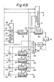
value detecting circuit 18, the digitisation code of which the predictive change amount is closest to the true value of the change amount Δr is selected by thecode selecting circuit 19. - It is also effective to execute the digitisation in such a manner as to accurately express two-dimensional changes in the horizontal direction, vertical direction, oblique direction and the like without limiting to the differences in the horizontal direction in the above embodiment. For instance, as shown in figure 6, in the case where the level of the objective pixel is x and the levels of the peripheral pixels at the upper position, left position and the upper oblique position are respectively a, b and c, the change amount Δr of the true value of the objective pixel and the predictive change amounts Δi (i = 0, 1, 2, 3) are obtained as the differences between the average values of the levels of the peripheral pixels and the level of the objective pixel. That is,
Δr = (3x - a - b - c)
Δi = (3Ii -A - B - C)
where, A, B and C denote levels which are obtained by decoding the digitisation codes derived with respect to a, b and c respectively. The digitisation code signal generating Δi which is closest to Δr is selected. - To obtain the change amount in the space, the predictive value obtained by the spatial prediction can be also used without limiting to the average value. That is, assuming that a predictive value is x′,
x′ = b + 1/2 (c - a)
Δr = x - x′ = x -b - 1/2(c - a)
Δi = Ii - B - 1/2 (C - A) - In a manner similar to the above, the digitisation code signal generating Δi which is closest to Δr is selected.
- Furthermore, the present invention can be applied to a digitising circuit in other highly efficient coding such as ADRC of a variable length, ADRC of a three-dimensional block, etc.
- When the first embodiment is applied to an image signal having a change shown by a
solid line 41 as in figure 2, the data of the respective pixels are digitised to have the decoding representative value shown by □, and therefore the change of the reconstructed image results in a smooth change similarly to the original signal as shown by abroken line 43. In the manner, according to the first embodiment, the spatial change of the original image signal can be preserved, so that the generation of the visually conspicuous noises in the reconstructed image can be prevented. - Now, a second embodiment of the present invention will be described with reference to the drawings.
- In figure 7, a digital video signal in which, for instance, one pixel (one sample) is digitised into eight bits is supplied to an input terminal shown by
reference numeral 101. The order of the data of the input digital video signal is changed from the scanning order to the order of blocks by ablock segmentation circuit 2. Since the maximum value and minimumvalue detecting circuit 103, subtractingcircuit 104 andframe segmentation circuit 105 havingoutput terminal 106 have the same construction as thecircuits - The output signal of the
block segmentation circuit 102 is supplied to one of the input terminals of a subtractingcircuit 109 throughdelay circuits delay circuit 107 corresponds to the time necessary to detect the maximum and minimum value. The output signal of thedelay circuit 107 is supplied to the other input terminal of the subtractingcircuit 109. A difference Δt in the time direction of the original pixel data (true value) is calculated. Assuming that a true value of the objective pixel is set to x1 and a true value of a reference pixel which is preceding by one frame period is set to x10, then Δt = x1 - x10. - The difference Δt between the true values of the image data from the subtracting
circuit 109 is supplied to subtractingcircuits value detecting circuit 114 and the minimum output signal is detected. The detection signal of the minimumvalue detecting circuit 114 is supplied to acode selecting circuit 115 and a two-bit digitisation code DT is generated from thecode selecting circuit 115. The digitisation code DT is transmitted through theframe segmentation circuit 105. In thecode selecting circuit 115, one of the two-bit digitisation codes (00), (01), (10) and (11) corresponding to the decoding representative levels I0, I1, I2 and I3 is selected. - The selecting operation of the
code selecting circuit 115 is as follows. - When r0 is minimum, (00) is selected as the digitisation code DT.
- When r1 is minimum, (01) is selected as the digitisation code DT.
- When r2 is minimum, (10) is selected as the digitisation code DT.
- When r3 is minimum, (11) is selected as the digitisation code DT.
- Signals Δ00, Δ01, Δ02 and Δ03 are supplied from subtracting
circuits value detecting circuit 114 detect among the signals Δ00-Δ03, the one closest to the difference Δt in the time direction of the true value of the image data. In other words, a digitisation code DT corresponding to the decoding representative level which generates the change closest to the signal change in one frame period of the original image signal is selected with respect to the objective pixel. - To the subtracting circuits 116-119, decoding representative levels (MIN + I0), (MIN + I1), (MIN + I2) and (MIN + I3) formed by the
local decoders terminals - The decoding level X10 of the reference pixel is formed by a
local decoder 128 and adelay circuits 129 having the delay amount DL2 of one frame period. The digitisation data DT from thecode selecting circuit 115 is supplied to alocal decoder 128. A decoding level of the objective pixel is generated from thelocal decoder 128. By passing the decoding level through adelay circuit 129, the decoding level x10 of the reference pixel is obtained. - The decoding level is supplied to the subtracting circuits 116-119. Therefore, the signals Δ00 to Δ03 which are respectively generated from the subtracting circuits 116-119 correspond to the predictive difference between the four decoding representative levels and the decoding level X10 of the preceding pixel as will be shown below.
Δ00 = (I0 + MIN) - X10
Δ01 = (I1 + MIN) - X10
Δ02 = (I2 + MIN) - X10
Δ03 = (I3 + MIN) - X10 - In the subtracting circuits 110-113, the following output signals are formed.
r0 = Δt - Δ00
r1 = Δt - Δ01
r2 = Δt - Δ02
r3 = Δt - Δ03 - Since the minimum one of r0-r3 is detected by the minimum
value detecting circuit 114, the digitisation code of which the predictive change amount is closest to the true value of the change amount Δt of the true value is selected by thecode selecting circuit 115. - According to the second embodiment, time dependent change of the original image signal can be preserved so that the generation of the visually conspicuous noises in the reconstructed image can be prevented.
- However, according to the first embodiment in which the spatial signal change can be preserved, the generation of the noises in the time direction cannot be prevented. On the other hand, according to the second embodiment in which the time dependent signal change can be preserved, the generation of the spatial noses cannot be prevented. Moreover, the digitising system in which such signal changes are significant has a problem such that errors are accumulated.
- Therefore, in the third embodiment, a highly efficient coding apparatus which can be adapted preferably to the characteristics such as pattern, movement amount of a picture, and the like of an image and which can improve the picture quality of the reconstructed image visually will be described hereinbelow with reference to figure 8.
- In figure 8, a digital video signal in which, for instance, one pixel (one sample) is digitised into eight bits is supplied to an input terminal shown by
reference numeral 201. The order of the data of the input digital video signal is changed from the scanning order to the order of blocks by ablock segmentation circuit 202. - Since the
circuits circuits - The output signal of the
block segmentation circuit 202 is supplied to inputterminals distortion detecting circuit 208, an inner spacechange detecting circuit 209, and a time dependentchange detecting circuit 210 through adelay circuit 207. The delay amount DL1 of thedelay circuit 207 corresponds to the time necessary to detect the maximum and minimum values. - The
distortion detecting circuit 208 is the first arithmetic operating circuit for respectively arithmetically operating differences α0, α1, α2 and α3 between a true value x1 of the objective pixel and four decoding representative values corresponding to the number of bits. The decoding representative values are formed bylocal decoders terminals 245, 246, 247 and 248 to the local decoders 241 to 244, respectively. In addition, the dynamic range DR and the minimum value MIN are supplied to the local decoders 241 to 244. Thedistortion detecting circuit 208 hasinput terminals output terminals - The inner space
change detecting circuit 209 is the second arithmetic operating circuit for calculating a spatial first change amount Δr from the true value of the objective pixel and the true value of a peripheral pixel which spatially locates in the periphery, for calculating spatial second change amounts Δ0, Δ1, Δ2 and Δ3 from the decoding value of the digitisation code of the peripheral pixel and the decoding representative values, and for calculating differences β0, β1, β2 and β3 between the first change amount Δr and the second change amounts Δ0 to Δ3. The inner spacechange detecting circuit 209 hasinput terminals input terminal 226 to which the decoded value of the digitisation code DT is supplied, andoutput terminals - The decoded value of the digitisation code DT is formed by a
local decoder 257. The dynamic range DR, the minimum value MIN, and the digitisation code DT are supplied to thelocal decoder 257 and the level corresponding to the digitisation code Dt is reconstructed by the decoding of the ADRC. Thelocal decoders - The time dependent
change detecting circuit 210 is the third arithmetic operating circuit for calculating a time dependent third change amount Δt from the true value of the objective pixel and a true value of a reference pixel which is time precedent to the objective pixel and spatially corresponds thereto, for calculating time dependent fourth change amounts Δ00, Δ01,Δ02 and Δ03 from the decoded value of the digitisation code of the reference pixel and the decoding representative values, and for calculating differences r0, r1, r2 and r3 between the third change amount Δt and the fourth change amounts Δ00 toΔ03. The time dependentchange detecting circuit 220 hasinput terminals input terminal 236 to which the decoded value of the digitisation code is supplied, andoutput terminals - Respective output signals of the
distortion detecting circuit 208, inner spacechange detecting circuit 209, and time dependentchange detecting circuit 210 are synthesised byweighting adding circuits - Assuming that w0, w1, w2 and w3 denote weighting coefficients, the
weighting adding circuit 251 generates a synthesised output δ0 which is expressed as follows.
w0α0 + w1β0 + w2r0 = δ0 - In a manner similar to the above, the
weighting adding circuits
w0α1 + w1β1 + w2r1 = δ1
w0α2 + w1β2 + w2r2 = δ2
w0α3 + w1β3 + w2r3 = δ3 - Fixed values or variable values may be used as the weighting coefficients w0 to w2 and they are set in consideration of the characteristics of the input image or the like.
- The synthesised outputs δ1 to δ3 from the
weighting adding circuits 251 to 254 are supplied to a minimumvalue detecting circuit 255. The minimumvalue detecting circuit 255 generates a detection signal indicative of the minimum one of the synthesised outputs δ1 to δ3. The detection signal is supplied to acode selecting circuit 256. The digitisation code DT of two bits which is specified by the detection signal is generated from thecode selecting circuit 256. The digitisation code DT is transmitted through theframe segmentation circuit 205. That is, in thecode selecting circuit 256, one of the two-bit digitisation codes (00), (01), (10) and (11) corresponding to the decoding representative levels I0, I1, I2 and I3 is selected. - The selecting operation of the
code selecting circuit 256 is as follows. - When δ0 is minimum, (00) is selected as the digitisation code DT.
- When δ1 is minimum, (01) is selected as the digitisation code DT.
- When δ2 is minimum, (10) is selected as the digitisation code DT.
- When δ3 is minimum, (11) is selected as the digitisation code DT.
- Although not shown, on the reception side, the reception data is supplied to a frame desegmentation circuit and the dynamic range DR, the minimum value MIN, and the digitisation code DT are separated by the frame desegmentation circuit. The dynamic range DR and the digitisation code DT are supplied to the ROMs. The decoding level after the minimum value was eliminated is formed. The minimum value MIN is added to the decoding level. Further, the reconstruction levels obtained as the results of the addition are changed to the original scanning order by a block separating circuit.
- As shown in figure 9, the
distortion detecting circuit 208 comprises subtractingcircuits input terminal 211 to the subtracting circuits 261 to 264, respectively. On the other hand, the decoding representative levels (MIN + I0), (MIN + I1), (MIN + I2) and (MIN _ I3) are supplied from theinput terminals 212 to 215 to the subtracting circuits 261 to 264, respectively. Therefore, the following output signals α0 to α3 are obtained at theoutput terminals 217 to 220 of the subtracting circuits 261 to 264, respectively.
α0 = (I0 + MIN) - x1
α1 = (I1 + MIN) - x1
α2 = (I2 + MIN) - x1
α3 = (I3 + MIN) - x1 - The output signals α0 to α3 of the above
distortion detecting circuit 208 indicate the differences between the true value x1 of the objective pixel and the decoding representative levels. The two-bit digitisation code corresponding to the minimum one of the α0 to α3 expresses x1 by the minimum distortion (the S/N ratio is best). - The inner space
change detecting circuit 209 has a construction corresponding to that shown in figure 4. Similarly the construction of the time dependentchange detecting circuit 210 corresponds to that shown in figure 7. Therefore, the detailed description of thesecircuits - The third embodiment is adapted to the characteristics such as pattern, movement amount, and the like of the original image signal and the S/N ratio can be improved. The spatial change or time dependent change of the original image signal can be preserved, so that the generation of visually conspicuous noises in the reconstructed image can be prevented.
- Having described a specific preferred embodiment of the present invention with reference to the accompanying drawings, it is to be understood that the invention is not limited to that precise embodiment, and that various changes and modifications may be effected therein by one skilled in the art without departing from the scope of the invention as defined in the appended claims.
Claims (6)
first detecting means for detecting a first difference between an original digital value of a first picture element to be encoded and an original digital value of a spatially adjacent picture element of said first picture element,
first local decoding means for decoding encoded video data of said spatially adjacent picture element to generate a first decoded value, and
generating means for generating compressed encoded video data of said first picture element wherein the difference between the decoded value of said compressed encoded video data and said first decoded value is closest to said first difference.
first detecting means for detecting a first difference between an original value of a first picture element to be encoded and an original digital value of a time-adjacent and spatially identical picture element of said first picture element,
first local decoding means for decoding encoded video data of said time-adjacent and spatially identical picture element to generate a first decoded value, and
generating means for generating compressed encoded video data of said first picture element wherein the difference between the decoded value of said compressed encoded video data and said first decoded value is closest to said first difference.
first local decoding means for decoding all compressed code data and for generating decoded values for a first picture element to be encoded,
first detecting means for detecting first differences between an original digital value of said first picture element and said each of said decoded values,
second detecting means for detecting second differences between a difference value of the original digital value of said first picture element and an original digital value of a spatially adjacent picture element of said first element and difference values of said decoded values and a decoded value of an encoded data of said spatially adjacent picture element,
third detecting means for detecting third differences between a difference value of the original digital value of said first picture element and an original digital value of timely adjacent and spatially identical picture element of said first element and difference values of said decoded values and a decoded value of an encoded data of said timely adjacent and spatially identical picture element,
weighting and adding means for multiplying first, second and third weighting coefficients to said first, second and third differences, respectively and for adding corresponding ones of the multiplied first, second and third differences together to generate added values,
minimum detecting means supplied with said added values and for detecting a minimum value thereof, and
code selecting means for selecting one of compressed code data corresponding to said minimum value.
Applications Claiming Priority (6)
| Application Number | Priority Date | Filing Date | Title |
|---|---|---|---|
| JP24522988A JP2621421B2 (en) | 1988-09-29 | 1988-09-29 | Image data quantization circuit |
| JP24523088A JP2621422B2 (en) | 1988-09-29 | 1988-09-29 | Image data quantization circuit |
| JP24522888A JP2606319B2 (en) | 1988-09-29 | 1988-09-29 | Image data quantization circuit |
| JP245229/88 | 1988-09-29 | ||
| JP245230/88 | 1988-09-29 | ||
| JP245228/88 | 1988-09-29 |
Publications (2)
| Publication Number | Publication Date |
|---|---|
| EP0368460A1 true EP0368460A1 (en) | 1990-05-16 |
| EP0368460B1 EP0368460B1 (en) | 1994-08-03 |
Family
ID=27333332
Family Applications (1)
| Application Number | Title | Priority Date | Filing Date |
|---|---|---|---|
| EP89309707A Expired - Lifetime EP0368460B1 (en) | 1988-09-29 | 1989-09-25 | Coding apparatus |
Country Status (4)
| Country | Link |
|---|---|
| US (1) | US4953023A (en) |
| EP (1) | EP0368460B1 (en) |
| CA (1) | CA1324435C (en) |
| DE (1) | DE68917260T2 (en) |
Cited By (2)
| Publication number | Priority date | Publication date | Assignee | Title |
|---|---|---|---|---|
| EP0460431A1 (en) * | 1990-06-07 | 1991-12-11 | Rautaruukki Oy | A method of and an equipment for optical inspection of strip and sheet products |
| WO1996029680A1 (en) * | 1995-03-21 | 1996-09-26 | International Business Machines Corporation | Interframe coding method and apparatus |
Families Citing this family (74)
| Publication number | Priority date | Publication date | Assignee | Title |
|---|---|---|---|---|
| DE69031638T2 (en) * | 1989-05-19 | 1998-03-19 | Canon Kk | System for the transmission of image information |
| US5193003A (en) * | 1989-08-15 | 1993-03-09 | Sony Corporation | Apparatus for decoding digital video data with small memory requirement |
| US5072296A (en) * | 1990-02-23 | 1991-12-10 | Massachusetts Institute Of Technology | Video frame reduction/reconstruction method and apparatus |
| US5164828A (en) * | 1990-02-26 | 1992-11-17 | Sony Corporation | Video signal transmission and method and apparatus for coding video signal used in this |
| KR940011600B1 (en) * | 1991-12-16 | 1994-12-22 | 삼성전자 주식회사 | Adaptive constant generating method and circuit of adaptive modulator |
| US5337085A (en) * | 1992-04-10 | 1994-08-09 | Comsat Corporation | Coding technique for high definition television signals |
| KR950005621B1 (en) * | 1992-09-30 | 1995-05-27 | 주식회사금성사 | Image decoder |
| US5850261A (en) * | 1992-10-15 | 1998-12-15 | Sony Corporation | Efficient variable length encoder and decoder |
| US5544286A (en) * | 1993-01-29 | 1996-08-06 | Microsoft Corporation | Digital video data compression technique |
| AU722393B2 (en) * | 1996-11-07 | 2000-08-03 | Broderbund Software, Inc. | System for adaptive animation compression |
| US6282684B1 (en) | 1997-10-23 | 2001-08-28 | Sony Corporation | Apparatus and method for recovery of data in a lossy transmission environment |
| US6311297B1 (en) * | 1997-10-23 | 2001-10-30 | Sony Corporation | Apparatus and method for mapping an image to blocks to provide for robust error recovery in a lossy transmission environment |
| US6581170B1 (en) | 1997-10-23 | 2003-06-17 | Sony Corporation | Source coding to provide for robust error recovery during transmission losses |
| US6170074B1 (en) | 1999-02-12 | 2001-01-02 | Sony Corporation | Source coding to provide for robust error recovery |
| US6307560B1 (en) | 1999-02-12 | 2001-10-23 | Sony Corporation | Classified adaptive spatio-temporal format conversion method and apparatus |
| US6519369B1 (en) | 1999-02-12 | 2003-02-11 | Sony Corporation | Method and apparatus for filter tap expansion |
| US6591398B1 (en) | 1999-02-12 | 2003-07-08 | Sony Corporation | Multiple processing system |
| US6154761A (en) * | 1999-02-12 | 2000-11-28 | Sony Corporation | Classified adaptive multiple processing system |
| US6192161B1 (en) | 1999-02-12 | 2001-02-20 | Sony Corporation | Method and apparatus for adaptive filter tap selection according to a class |
| US6535148B1 (en) | 1999-02-12 | 2003-03-18 | Sony Corporation | Method and apparatus for truncated decoding |
| US6151416A (en) * | 1999-02-12 | 2000-11-21 | Sony Corporation | Method and apparatus for adaptive class tap selection according to multiple classification |
| US6621936B1 (en) | 1999-02-12 | 2003-09-16 | Sony Corporation | Method and apparatus for spatial class reduction |
| US6307979B1 (en) | 1999-02-12 | 2001-10-23 | Sony Corporation | Classified adaptive error recovery method and apparatus |
| US7010737B2 (en) * | 1999-02-12 | 2006-03-07 | Sony Corporation | Method and apparatus for error data recovery |
| US6178266B1 (en) | 1999-02-12 | 2001-01-23 | Sony Corporation | Method and apparatus for the recovery of compression constants in the encoded domain |
| US6363118B1 (en) | 1999-02-12 | 2002-03-26 | Sony Corporation | Apparatus and method for the recovery of compression constants in the encoded domain |
| US6697489B1 (en) | 1999-03-30 | 2004-02-24 | Sony Corporation | Method and apparatus for securing control words |
| US7565546B2 (en) | 1999-03-30 | 2009-07-21 | Sony Corporation | System, method and apparatus for secure digital content transmission |
| US7730300B2 (en) | 1999-03-30 | 2010-06-01 | Sony Corporation | Method and apparatus for protecting the transfer of data |
| US6549672B1 (en) * | 1999-06-29 | 2003-04-15 | Sony Corporation | Method and apparatus for recovery of encoded data using central value |
| US6473876B1 (en) | 1999-06-29 | 2002-10-29 | Sony Corporation | Method and apparatus for encoding of bitstreams using rotation |
| US6493842B1 (en) | 1999-06-29 | 2002-12-10 | Sony Corporation | Time-varying randomization for data synchronization and implicit information transmission |
| US6389562B1 (en) | 1999-06-29 | 2002-05-14 | Sony Corporation | Source code shuffling to provide for robust error recovery |
| US6351494B1 (en) | 1999-09-24 | 2002-02-26 | Sony Corporation | Classified adaptive error recovery method and apparatus |
| US6522785B1 (en) | 1999-09-24 | 2003-02-18 | Sony Corporation | Classified adaptive error recovery method and apparatus |
| US7039614B1 (en) | 1999-11-09 | 2006-05-02 | Sony Corporation | Method for simulcrypting scrambled data to a plurality of conditional access devices |
| US6539517B1 (en) | 1999-11-09 | 2003-03-25 | Sony Corporation | Data transformation for explicit transmission of control information |
| US6754371B1 (en) | 1999-12-07 | 2004-06-22 | Sony Corporation | Method and apparatus for past and future motion classification |
| US7225164B1 (en) | 2000-02-15 | 2007-05-29 | Sony Corporation | Method and apparatus for implementing revocation in broadcast networks |
| US20030206631A1 (en) * | 2000-06-22 | 2003-11-06 | Candelore Brant L. | Method and apparatus for scrambling program data for furture viewing |
| US7124303B2 (en) | 2001-06-06 | 2006-10-17 | Sony Corporation | Elementary stream partial encryption |
| US7350082B2 (en) | 2001-06-06 | 2008-03-25 | Sony Corporation | Upgrading of encryption |
| US7895616B2 (en) | 2001-06-06 | 2011-02-22 | Sony Corporation | Reconstitution of program streams split across multiple packet identifiers |
| US7747853B2 (en) | 2001-06-06 | 2010-06-29 | Sony Corporation | IP delivery of secure digital content |
| US7765567B2 (en) | 2002-01-02 | 2010-07-27 | Sony Corporation | Content replacement by PID mapping |
| US7376233B2 (en) | 2002-01-02 | 2008-05-20 | Sony Corporation | Video slice and active region based multiple partial encryption |
| US7039938B2 (en) | 2002-01-02 | 2006-05-02 | Sony Corporation | Selective encryption for video on demand |
| US7292691B2 (en) | 2002-01-02 | 2007-11-06 | Sony Corporation | Progressive video refresh slice detection |
| US7242773B2 (en) | 2002-09-09 | 2007-07-10 | Sony Corporation | Multiple partial encryption using retuning |
| US7233669B2 (en) | 2002-01-02 | 2007-06-19 | Sony Corporation | Selective encryption to enable multiple decryption keys |
| US7155012B2 (en) | 2002-01-02 | 2006-12-26 | Sony Corporation | Slice mask and moat pattern partial encryption |
| US7302059B2 (en) | 2002-01-02 | 2007-11-27 | Sony Corporation | Star pattern partial encryption |
| US7218738B2 (en) | 2002-01-02 | 2007-05-15 | Sony Corporation | Encryption and content control in a digital broadcast system |
| US7823174B2 (en) | 2002-01-02 | 2010-10-26 | Sony Corporation | Macro-block based content replacement by PID mapping |
| US7215770B2 (en) | 2002-01-02 | 2007-05-08 | Sony Corporation | System and method for partially encrypted multimedia stream |
| US7530084B2 (en) | 2002-05-28 | 2009-05-05 | Sony Corporation | Method and apparatus for synchronizing dynamic graphics |
| US8818896B2 (en) | 2002-09-09 | 2014-08-26 | Sony Corporation | Selective encryption with coverage encryption |
| US7724907B2 (en) | 2002-11-05 | 2010-05-25 | Sony Corporation | Mechanism for protecting the transfer of digital content |
| US8572408B2 (en) | 2002-11-05 | 2013-10-29 | Sony Corporation | Digital rights management of a digital device |
| US8667525B2 (en) | 2002-12-13 | 2014-03-04 | Sony Corporation | Targeted advertisement selection from a digital stream |
| US8645988B2 (en) | 2002-12-13 | 2014-02-04 | Sony Corporation | Content personalization for digital content |
| US20040165586A1 (en) * | 2003-02-24 | 2004-08-26 | Read Christopher Jensen | PID filters based network routing |
| US7409702B2 (en) | 2003-03-20 | 2008-08-05 | Sony Corporation | Auxiliary program association table |
| US7292692B2 (en) | 2003-03-25 | 2007-11-06 | Sony Corporation | Content scrambling with minimal impact on legacy devices |
| US7286667B1 (en) | 2003-09-15 | 2007-10-23 | Sony Corporation | Decryption system |
| US7853980B2 (en) | 2003-10-31 | 2010-12-14 | Sony Corporation | Bi-directional indices for trick mode video-on-demand |
| US7346163B2 (en) | 2003-10-31 | 2008-03-18 | Sony Corporation | Dynamic composition of pre-encrypted video on demand content |
| US7343013B2 (en) | 2003-12-16 | 2008-03-11 | Sony Corporation | Composite session-based encryption of video on demand content |
| US7263187B2 (en) | 2003-10-31 | 2007-08-28 | Sony Corporation | Batch mode session-based encryption of video on demand content |
| US7620180B2 (en) | 2003-11-03 | 2009-11-17 | Sony Corporation | Preparation of content for multiple conditional access methods in video on demand |
| US8041190B2 (en) | 2004-12-15 | 2011-10-18 | Sony Corporation | System and method for the creation, synchronization and delivery of alternate content |
| US7895617B2 (en) | 2004-12-15 | 2011-02-22 | Sony Corporation | Content substitution editor |
| US8185921B2 (en) | 2006-02-28 | 2012-05-22 | Sony Corporation | Parental control of displayed content using closed captioning |
| US7555464B2 (en) | 2006-03-01 | 2009-06-30 | Sony Corporation | Multiple DRM management |
Citations (6)
| Publication number | Priority date | Publication date | Assignee | Title |
|---|---|---|---|---|
| US3502815A (en) * | 1967-03-17 | 1970-03-24 | Xerox Corp | Tone signalling bandwidth compression system |
| EP0142767A2 (en) * | 1983-11-21 | 1985-05-29 | International Business Machines Corporation | Manipulation of graphics image data |
| USRE32291E (en) * | 1974-09-09 | 1986-11-18 | Kokusai Denshin Denwa Kabushiki Kaisha | System for coding information change picture elements in facsimile signal |
| US4701807A (en) * | 1983-09-22 | 1987-10-20 | Canon Kabushiki Kaisha | Method and apparatus for processing an image |
| US4710822A (en) * | 1982-09-21 | 1987-12-01 | Konishiroku Photo Industry Co., Ltd. | Image processing method |
| EP0310021A2 (en) * | 1987-09-28 | 1989-04-05 | Dainippon Screen Mfg. Co., Ltd. | Gradation converting circuit employing lookup table |
Family Cites Families (5)
| Publication number | Priority date | Publication date | Assignee | Title |
|---|---|---|---|---|
| US32291A (en) * | 1861-05-14 | Henry s | ||
| GB2050752B (en) * | 1979-06-07 | 1984-05-31 | Japan Broadcasting Corp | Motion compensated interframe coding system |
| US4442454A (en) * | 1982-11-15 | 1984-04-10 | Eastman Kodak Company | Image processing method using a block overlap transformation procedure |
| JPS61114677A (en) * | 1984-11-09 | 1986-06-02 | Nec Corp | Adaptability prediction coding decoding system and device for animation signal |
| KR910000707B1 (en) * | 1986-05-26 | 1991-01-31 | 미쓰비시덴기 가부시기가이샤 | Method and apparatus for encoding transmitting |
-
1989
- 1989-09-15 US US07/407,753 patent/US4953023A/en not_active Expired - Lifetime
- 1989-09-20 CA CA000612054A patent/CA1324435C/en not_active Expired - Fee Related
- 1989-09-25 EP EP89309707A patent/EP0368460B1/en not_active Expired - Lifetime
- 1989-09-25 DE DE68917260T patent/DE68917260T2/en not_active Expired - Fee Related
Patent Citations (6)
| Publication number | Priority date | Publication date | Assignee | Title |
|---|---|---|---|---|
| US3502815A (en) * | 1967-03-17 | 1970-03-24 | Xerox Corp | Tone signalling bandwidth compression system |
| USRE32291E (en) * | 1974-09-09 | 1986-11-18 | Kokusai Denshin Denwa Kabushiki Kaisha | System for coding information change picture elements in facsimile signal |
| US4710822A (en) * | 1982-09-21 | 1987-12-01 | Konishiroku Photo Industry Co., Ltd. | Image processing method |
| US4701807A (en) * | 1983-09-22 | 1987-10-20 | Canon Kabushiki Kaisha | Method and apparatus for processing an image |
| EP0142767A2 (en) * | 1983-11-21 | 1985-05-29 | International Business Machines Corporation | Manipulation of graphics image data |
| EP0310021A2 (en) * | 1987-09-28 | 1989-04-05 | Dainippon Screen Mfg. Co., Ltd. | Gradation converting circuit employing lookup table |
Cited By (4)
| Publication number | Priority date | Publication date | Assignee | Title |
|---|---|---|---|---|
| EP0460431A1 (en) * | 1990-06-07 | 1991-12-11 | Rautaruukki Oy | A method of and an equipment for optical inspection of strip and sheet products |
| US5263094A (en) * | 1990-06-07 | 1993-11-16 | Rautaruukki Oy | Method of and an equipment for optical inspection of strip and sheet products |
| WO1996029680A1 (en) * | 1995-03-21 | 1996-09-26 | International Business Machines Corporation | Interframe coding method and apparatus |
| US6088394A (en) * | 1995-03-21 | 2000-07-11 | International Business Machines Corporation | Efficient interframe coding method and apparatus utilizing selective sub-frame differencing |
Also Published As
| Publication number | Publication date |
|---|---|
| EP0368460B1 (en) | 1994-08-03 |
| DE68917260D1 (en) | 1994-09-08 |
| DE68917260T2 (en) | 1995-02-23 |
| CA1324435C (en) | 1993-11-16 |
| US4953023A (en) | 1990-08-28 |
Similar Documents
| Publication | Publication Date | Title |
|---|---|---|
| EP0368460B1 (en) | Coding apparatus | |
| EP0185533B1 (en) | High efficiency technique for coding a digital video signal | |
| KR100289592B1 (en) | Layer encoding and decoding device for digital video signal | |
| EP0181215B1 (en) | Apparatus for detecting motion of television images | |
| JP2509469B2 (en) | Method and apparatus for adaptive encoding and decoding of continuous image by conversion | |
| EP0385654B1 (en) | Highly efficient coding apparatus | |
| EP0193185B1 (en) | Interframe adaptive vector quantization encoding apparatus | |
| EP0227439A2 (en) | Method of and apparatus for transmitting digital data and apparatus for decoding digital data | |
| EP0508351A2 (en) | Method and apparatus for the motion compensated predictive coding of an image signal | |
| US5561532A (en) | Image reproducing apparatus | |
| US4430670A (en) | Reconstruction of quantized DPCM or PCM signals | |
| EP1420585B1 (en) | Picture information converting apparatus and method thereof | |
| EP0364261B1 (en) | Highly efficient coding apparatus | |
| EP0454234B1 (en) | Processing picture signals | |
| JP2621422B2 (en) | Image data quantization circuit | |
| EP0528366B1 (en) | Method and circuit arrangement for movement detection in a television picture | |
| JPH088684B2 (en) | High efficiency code decoding device | |
| JP2606319B2 (en) | Image data quantization circuit | |
| JP2637973B2 (en) | Block encoding decoding device | |
| JPH03247077A (en) | Adaptive contour prediction coding system by edge detection | |
| JP2629315B2 (en) | High-efficiency coding device for image signals | |
| JP2910213B2 (en) | High efficiency coding apparatus and method | |
| JP2712298B2 (en) | High-efficiency code decoding device | |
| JP2832972B2 (en) | Image data quantization circuit | |
| JP2832959B2 (en) | High-efficiency coding device for image signals |
Legal Events
| Date | Code | Title | Description |
|---|---|---|---|
| PUAI | Public reference made under article 153(3) epc to a published international application that has entered the european phase |
Free format text: ORIGINAL CODE: 0009012 |
|
| AK | Designated contracting states |
Kind code of ref document: A1 Designated state(s): DE FR GB NL |
|
| 17P | Request for examination filed |
Effective date: 19901009 |
|
| 17Q | First examination report despatched |
Effective date: 19921217 |
|
| GRAA | (expected) grant |
Free format text: ORIGINAL CODE: 0009210 |
|
| AK | Designated contracting states |
Kind code of ref document: B1 Designated state(s): DE FR GB NL |
|
| REF | Corresponds to: |
Ref document number: 68917260 Country of ref document: DE Date of ref document: 19940908 |
|
| ET | Fr: translation filed | ||
| PLBE | No opposition filed within time limit |
Free format text: ORIGINAL CODE: 0009261 |
|
| STAA | Information on the status of an ep patent application or granted ep patent |
Free format text: STATUS: NO OPPOSITION FILED WITHIN TIME LIMIT |
|
| 26N | No opposition filed | ||
| PGFP | Annual fee paid to national office [announced via postgrant information from national office to epo] |
Ref country code: FR Payment date: 19950911 Year of fee payment: 7 |
|
| PGFP | Annual fee paid to national office [announced via postgrant information from national office to epo] |
Ref country code: GB Payment date: 19950918 Year of fee payment: 7 |
|
| PGFP | Annual fee paid to national office [announced via postgrant information from national office to epo] |
Ref country code: NL Payment date: 19950922 Year of fee payment: 7 |
|
| PGFP | Annual fee paid to national office [announced via postgrant information from national office to epo] |
Ref country code: DE Payment date: 19950928 Year of fee payment: 7 |
|
| PG25 | Lapsed in a contracting state [announced via postgrant information from national office to epo] |
Ref country code: GB Effective date: 19960925 |
|
| PG25 | Lapsed in a contracting state [announced via postgrant information from national office to epo] |
Ref country code: FR Effective date: 19960930 |
|
| PG25 | Lapsed in a contracting state [announced via postgrant information from national office to epo] |
Ref country code: NL Effective date: 19970401 |
|
| GBPC | Gb: european patent ceased through non-payment of renewal fee |
Effective date: 19960925 |
|
| NLV4 | Nl: lapsed or anulled due to non-payment of the annual fee |
Effective date: 19970401 |
|
| PG25 | Lapsed in a contracting state [announced via postgrant information from national office to epo] |
Ref country code: DE Effective date: 19970603 |
|
| REG | Reference to a national code |
Ref country code: FR Ref legal event code: ST |
|
| REG | Reference to a national code |
Ref country code: FR Ref legal event code: ST |