EP0368334A2 - Etching apparatus and method of using the same - Google Patents
Etching apparatus and method of using the same Download PDFInfo
- Publication number
- EP0368334A2 EP0368334A2 EP89120883A EP89120883A EP0368334A2 EP 0368334 A2 EP0368334 A2 EP 0368334A2 EP 89120883 A EP89120883 A EP 89120883A EP 89120883 A EP89120883 A EP 89120883A EP 0368334 A2 EP0368334 A2 EP 0368334A2
- Authority
- EP
- European Patent Office
- Prior art keywords
- semiconductor substrate
- vacuum chuck
- substrate
- etching
- end surface
- Prior art date
- Legal status (The legal status is an assumption and is not a legal conclusion. Google has not performed a legal analysis and makes no representation as to the accuracy of the status listed.)
- Granted
Links
Images

Classifications
-
- H—ELECTRICITY
- H01—ELECTRIC ELEMENTS
- H01L—SEMICONDUCTOR DEVICES NOT COVERED BY CLASS H10
- H01L21/00—Processes or apparatus adapted for the manufacture or treatment of semiconductor or solid state devices or of parts thereof
- H01L21/02—Manufacture or treatment of semiconductor devices or of parts thereof
- H01L21/04—Manufacture or treatment of semiconductor devices or of parts thereof the devices having at least one potential-jump barrier or surface barrier, e.g. PN junction, depletion layer or carrier concentration layer
- H01L21/18—Manufacture or treatment of semiconductor devices or of parts thereof the devices having at least one potential-jump barrier or surface barrier, e.g. PN junction, depletion layer or carrier concentration layer the devices having semiconductor bodies comprising elements of Group IV of the Periodic System or AIIIBV compounds with or without impurities, e.g. doping materials
- H01L21/30—Treatment of semiconductor bodies using processes or apparatus not provided for in groups H01L21/20 - H01L21/26
- H01L21/302—Treatment of semiconductor bodies using processes or apparatus not provided for in groups H01L21/20 - H01L21/26 to change their surface-physical characteristics or shape, e.g. etching, polishing, cutting
- H01L21/306—Chemical or electrical treatment, e.g. electrolytic etching
-
- H—ELECTRICITY
- H01—ELECTRIC ELEMENTS
- H01L—SEMICONDUCTOR DEVICES NOT COVERED BY CLASS H10
- H01L21/00—Processes or apparatus adapted for the manufacture or treatment of semiconductor or solid state devices or of parts thereof
- H01L21/67—Apparatus specially adapted for handling semiconductor or electric solid state devices during manufacture or treatment thereof; Apparatus specially adapted for handling wafers during manufacture or treatment of semiconductor or electric solid state devices or components ; Apparatus not specifically provided for elsewhere
- H01L21/67005—Apparatus not specifically provided for elsewhere
- H01L21/67011—Apparatus for manufacture or treatment
- H01L21/67017—Apparatus for fluid treatment
- H01L21/67063—Apparatus for fluid treatment for etching
- H01L21/67075—Apparatus for fluid treatment for etching for wet etching
- H01L21/67086—Apparatus for fluid treatment for etching for wet etching with the semiconductor substrates being dipped in baths or vessels
-
- H—ELECTRICITY
- H01—ELECTRIC ELEMENTS
- H01L—SEMICONDUCTOR DEVICES NOT COVERED BY CLASS H10
- H01L21/00—Processes or apparatus adapted for the manufacture or treatment of semiconductor or solid state devices or of parts thereof
- H01L21/67—Apparatus specially adapted for handling semiconductor or electric solid state devices during manufacture or treatment thereof; Apparatus specially adapted for handling wafers during manufacture or treatment of semiconductor or electric solid state devices or components ; Apparatus not specifically provided for elsewhere
- H01L21/67005—Apparatus not specifically provided for elsewhere
- H01L21/67011—Apparatus for manufacture or treatment
- H01L21/67017—Apparatus for fluid treatment
- H01L21/67063—Apparatus for fluid treatment for etching
- H01L21/67075—Apparatus for fluid treatment for etching for wet etching
- H01L21/6708—Apparatus for fluid treatment for etching for wet etching using mainly spraying means, e.g. nozzles
-
- H—ELECTRICITY
- H01—ELECTRIC ELEMENTS
- H01L—SEMICONDUCTOR DEVICES NOT COVERED BY CLASS H10
- H01L21/00—Processes or apparatus adapted for the manufacture or treatment of semiconductor or solid state devices or of parts thereof
- H01L21/67—Apparatus specially adapted for handling semiconductor or electric solid state devices during manufacture or treatment thereof; Apparatus specially adapted for handling wafers during manufacture or treatment of semiconductor or electric solid state devices or components ; Apparatus not specifically provided for elsewhere
- H01L21/683—Apparatus specially adapted for handling semiconductor or electric solid state devices during manufacture or treatment thereof; Apparatus specially adapted for handling wafers during manufacture or treatment of semiconductor or electric solid state devices or components ; Apparatus not specifically provided for elsewhere for supporting or gripping
- H01L21/6838—Apparatus specially adapted for handling semiconductor or electric solid state devices during manufacture or treatment thereof; Apparatus specially adapted for handling wafers during manufacture or treatment of semiconductor or electric solid state devices or components ; Apparatus not specifically provided for elsewhere for supporting or gripping with gripping and holding devices using a vacuum; Bernoulli devices
Abstract
Description
- The present invention relates to an etching apparatus for semiconductor substrates (also called wafers) and, more particularly, to an etching apparatus for etching the end surfaces of semiconductor substrates.
- In the manufacture of semiconductor devices, an etching process is sometimes performed for only the end surface surface of a semiconductor substrate. For example, a disk-like wafer having no orientation flat is used as a semiconductor substrate for a large-power semiconductor device or the like, and the side surface of the wafer is inclined with respect to the major surfaces of the wafer so as to form a bevel structure to maintain a prescribed breakdown voltage. Since cracks and defects are produced on the inclined side surface of the wafer during beveling, they must be removed by etching. Such a conventional technique for etching only the end surface of a wafer will be described with reference to the accompanying drawings.
- As shown in Fig. 1A, after one major surface of a wafer 1 is entirely coated with an
antietching solution 2 using a brush, the wafer 1 is bonded to afluoroplastic disk 3 having the same diameter as that of the wafer 1. The wafer 1 and thedisk 3 are then placed on a hot plate with thedisk 3 facing down, and are baked for several minutes to be fixed on each other. After baking, the other major surface (pattern formation surface) of the wafer 1 is coated with theantietching solution 2 using a brush. The wafer 1 is then baked in the same manner as described above. In the above-described process, it is essential to prevent adhesion of the antietching solution to the end surface of the wafer 1. - As shown in Fig. 1B, the above-described wafer with the fluoroplastic disk is picked up with
tweezers 4 and is immersed in anetching solution 6 in anetching solution tank 5 for a predetermined period of time, thus etching only the end surface of the wafer. After etching, the etching solution is completely removed from the wafer with the disk by cleaning with water In addition, the wafer is immersed in a boiling organic solution so as to peel off thedisk 3 from the wafer 1 and to remove the antietching solution. Upon removal of the antietching solution, the wafer is picked up with the tweezers and is swung in a water flow tank to clean it. After cleaning, as shown in Fig. 1C, the wafer is placed below anultraviolet lamp 7 to dry it. - The following problems are posed in the above-described conventional etching means. (1) An anti-etching solution must be carefully coated on the major surfaces of a wafer so as to prevent the solution from adhering to the end surface of the wafer. Hence, the coating step requires a long period of time. (2) It takes an undesirably long period of time to bond a fluoroplastic disk to the wafer while preventing adhesion of the antietching solution to the end surface of the wafer. (3) In order to remove the hardened antietching solution after the wafer is immersed in the etching solution, the cumbersome subsequent steps are required: immersing the wafer in a boiling organic solution; cleaning in flowing water; and drying by means of a lamp. (4) After the fluoroplastic substrate is peeled off from the wafer, the wafer is picked up with tweezers so as to be set or reset in a drying process by means of a lamp. For this reason, the end surfaces of wafers tend to break (chip), resulting in a decrease in yield. (5) Since the coating film of an antietching solution on both the major surfaces of a wafer varies in thickness, the manufacturing yield is decreased. (6) Since an operator is required to perform a large number of steps, such as coating an antietching solution, bonding a fluoroplastic disk, peeling the antietching solution and the disk, and drying by means of a lamp, automation is delayed and a long period of time is required for these steps. (7) Large amounts of etching solution and organic solution are used. (8) Since harmful solutions are used, pollution problems are posed. (9) The delivery date of products is difficult to keep because of a large number of steps.
- As described above, in the conventional technique, the number of steps to be performed by an operator is large, and it is difficult to uniformly etch the end surface of a wafer, thus position problems in terms of quality and yield. In addition, a long period of time is required for the respective steps, such as etching, cleaning, and drying, and large amounts of etching solution, organic solution, and the like are used, thus posing a problem in terms of safety with respect to a human body.
- It is an object of the present invention to provide a semiconductor substrate etching apparatus, which can solve the various problems of the above-described conventional technique, and which can uniformly and automatically perform an etching process for only the end surface of a wafer in a short period of time, and can continuously and automatically perform cleaning and drying steps, thereby increasing the manufacturing yield, shortening the time required for the steps, reducing the amounts of chemicals to be used, and improving safety in operations.
- According to the present invention, there is provided a semiconductor substrate etching apparatus comprising: a rotatable first vacuum chuck having an elastic seal member, mounted around a peripheral portion of an upper surface thereof and having a diameter smaller than that of a semiconductor substrate (wafer), for holding the substrate in a horizontal state in contact with one major surface (to be referred to as a lower surface hereinafter) of the substrate, and a plurality of exhaust holes communicating with a hollow portion as an exhaust path therein and extending obliquely outward to open in the upper surface thereof, openings of the exhaust holes being arranged from the center of the upper surface to a periphery thereof in a straight line; a semiconductor substrate end surface etching mechanism including a roller arranged near the semiconductor substrate in a horizontal state and having a groove which is formed in an outer surface thereof so as to allow the end surface of the substrate to be inserted in a non-contact state and to cover the end surface, and means for supplying an etching solution, which is brought into contact with the end surface of the substrate, to the groove of the roller; a rotatable or non-rotatable second vacuum chuck, which can be horizontally and vertically moved and, which can hold the other major surface of the semiconductor substrate by suction and move the substrate to an upper position a predetermined distance away from the upper surface of the first vacuum chuck; an end surface cleaning nozzle, arranged to oppose a side surface of the semiconductor substrate held by the first vacuum chuck, for spraying a cleaning solution on the end surface thereof; a semiconductor substrate cleaning mechanism, arranged to oppose a side surface of a region defined by the predetermined distance between the upper surface of the first vacuum chuck and the lower surface of the substrate held by the second vacuum chuck, for spraying a cleaning solution on the region; and a semiconductor substrate drying mechanism for drying the lower surface of the semiconductor substrate by discharging a drying gas from the plurality of exhaust holes of the rotating first vacuum chuck onto the lower surface, and for drying the upper surface of the semiconductor substrate held by the first vacuum chuck upon rotation thereof.
- Note that the end surface of the semiconductor substrate is the side surface of the substrate including the peripheral portions of both the major surfaces of the substrate.
- The etching solution is supplied to the groove of the roller of the semiconductor substrate end surface etching mechanism from the etching solution supply means, e.g., an etching solution supply nozzle arranged near the roller. The etching solution substantially fills the groove by surface tension. Upon rotation of the roller and the first vacuum chuck, the end surface of the substrate is brought into contact with the etching solution with which the groove is filled, and part of the etching solution is transferred onto the end surface of the substrate, thereby performing an etching process. Since the etching solution is always replenished upon rotation of the roller and the substrate, a uniform and efficient etching process can be performed. The etching solution adhering to the peripheral portion of the upper surface of the substrate does not flow inward from the peripheral portion due to the centrifugal force generated upon rotation of the substrate. The etching solution adhering to the peripheral portion of the lower surface of the substrate does not flow to the inner portion of the lower surface because of the elastic seal member which is in tight contact with the substrate. When the substrate is directly chucked to the upper surface of the chuck without an elastic seal member, the phenomenon that an etching solution enters the inner portion of a substrate by vacuum suction was often recognized. By adding an elastic seal member, an etching region can be reliably limited to only the end surface of a substrate. After etching, the end surface of the substrate is cleaned by the cleaning solution sprayed from the end surface cleaning nozzle.
- Upon cleaning of the end surface, the semiconductor substrate is held by the second vacuum chuck by suction, and is moved upward and stopped at an upper position the predetermined distance away from the upper surface of the first vacuum chuck. The lower surface of the substrate and the upper surface of the first vacuum chuck are cleaned by the cleaning solution sprayed from the cleaning nozzle of the semiconductor substrate cleaning mechanism. During this cleaning operation, the drying gas is discharged from the exhaust holes open to the upper surface of the first vacuum chuck so as to prevent the cleaning solution from flowing in the exhaust holes. Since the first vacuum chuck is rotated, the flow of the gas sprayed from the rotating exhaust holes acts on the flow of the cleaning solution so as to shorten the time for cleaning. After cleaning, only the drying gas is fed to dry the upper surface of the first vacuum chuck and the lower surface of the substrate. Since the openings of the exhaust holes from which the drying gas is sprayed are arranged from the center of the upper surface of the rotating chuck to its periphery in a straight line, a surface to be treated can be uniformly dried within a short period of time. Note that the above-described effect can be obtained either by rotating the second vacuum chuck, which holds the substrate, or not rotating it during the cleaning and drying steps. However, the second vacuum chuck is preferably rotated in a direction opposite to that of the first vacuum chuck in order to enhance the above effect.
- Subsequently, the semiconductor substrate is held on the elastic seal member of the first vacuum chuck again in tight contact therewith. In this state, the cleaning solution is sprayed from the cleaning nozzle on the upper surface of the substrate to clean it. After cleaning, the first vacuum chuck is rotated at high speed to dry the upper surface of the substrate. In order to perform the drying operation within a short period of time, the first vacuum chuck is preferably rotated at a high rotational speed of at least 2,000 rpm or more.
- This invention can be more fully understood from the following detailed description when taken in conjunction with the accompanying drawings, in which:
- Figs. 1A to 1C are views showing conventional semiconductor substrate etching steps;
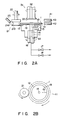
- Fig. 2A is a view showing an arrangement of a semiconductor substrate etching apparatus according to the present invention;
- Fig. 2B is a partial plan view of the semiconductor substrate etching apparatus of the present invention; and
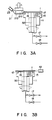
- Figs. 3A to 3D are views showing etching steps using the semiconductor substrate etching apparatus of the present invention.
- An embodiment of the present invention will be described below with reference to the accompanying drawings. Figs. 2A and 2B are views for explaining an arrangement of a semiconductor substrate etching apparatus of the present invention. Fig. 2A is a front view including a partially sectional view. Fig. 2B is a partial plan view of the apparatus.
- A rotary
first vacuum chuck 11 includes an elastic seal member 12 (an O-ring is used in this embodiment, and hence theseal member 12 will be referred to as an O-ring hereinafter.) Reference numeral 1 denotes a semiconductor substrate (wafer) whose end surface is to be etched. The O-ring 12 is constituted by a high-modulus member and has a diameter smaller than that of the substrate 1. The O-ring 12 is in tight contact with one major surface (to be referred to as a lower surface hereinafter) 1b of the substrate 1 to hold the substrate 1 in a horizontal state. The O-ring 12 is fitted in a notched portion which is formed in the peripheral portion of anupper surface 19 of thefirst vacuum chuck 11. Thefirst vacuum chuck 11 is fixed on a hollowrotating shaft 16. Ahollow portion 14, as an exhaust path, is formed inside thefirst vacuum chuck 11 so as to communicate with the hollow portion of therotating shaft 16. Several exhaust holes 15 are formed in thefirst vacuum chuck 11 so as to communicate with thehollow portion 14 and to obliquely extend outward at an angle of 45 or 60° to be open to theupper surface 19. The openings of the exhaust holes 15 are arranged from the center to the periphery in a straight line (see Fig. 2B). In this embodiment, the openings are radially arranged from the center of the upper surface in a straight line. However, the present invention is not limited to this. That is, the above arrangement may be curved or shifted from the radial direction. Alternatively, a plurality of such arrangements may be formed. The openings can be arranged in any of the above-described manners as long as they are inclined obliquely outward, as described above. The rotatingshaft 16 is coupled to a rotational driving unit (not shown). The rotational speed of therotating shaft 16 can be changed, and a rotational driving unit capable of rotating theshaft 16 at a high speed of 2,000 rpm or more as needed is used. One end of the hollow portion of therotating shaft 16 is connected to a vacuum pipe line and an N₂ gas pipe line in parallel throughvalves - An
etching mechanism 21 for the end surface of a semiconductor substrate includes aroller 21b fixed on arotating shaft 22, and an etching solution supply means (etching solution supply nozzle) 23. Theroller 21b is arranged near the substrate 1 in a horizontal state. A groove 21a is formed in the outer surface of theroller 21b. The groove 21a is shaped so as to allow the end surface of the substrate 1 to be inserted in a non-contact state, i.e., to cover the end surface of the substrate. The etching solution supply means 23 is a nozzle which is arranged near theroller 21b so as to supply an etching solution to the groove 21a of therotating roller 21b. Note that the etching solution supply means is not limited to the nozzle in this embodiment. For example, an etching solution supply path may be formed in therotating shaft 22 and theroller 21b so as to extend therethrough and to be open to the groove 21a. The rotatingshaft 22 is coupled to a rotational driving unit (not shown), and transmits rotation of a desired rotation speed to theroller 21b. - A
second vacuum chuck 31 is arranged at an upper position to oppose thefirst vacuum chuck 11 through the substrate 1, and is coupled to a driving unit (not shown) capable of horizontally and vertically moving thechuck 31. This driving unit includes a rotary mechanism, as needed, in order to rotate thesecond vacuum chuck 31 in cleaning and drying steps for substrates (to be described later). Anexhaust hole 32 is formed inside thesecond vacuum chuck 31 so as to communicate with a vacuum pipe line (not shown) and to be open to asuction surface 33. An elastic seal member is arranged around the peripheral portion of thesuction surface 33 as needed. Thesecond vacuum chuck 31 is designed to hold the other major surface (to be referred to as an upper surface hereinafter) of the substrate 1 by suction and to move and stop the substrate to an upper position which is a predetermined distance away from theupper surface 19. - A semiconductor
substrate cleaning mechanism 41 includes an endsurface cleaning nozzle 42 and a cleaningnozzle 43. The cleaningnozzle 42 is arranged at a position to oppose the side surface of the substrate 1 held by thefirst vacuum chuck 11 so that a cleaning solution can be sprayed on the end surface including the side surface of the substrate 1. The cleaningnozzle 43 is arranged at a position to oppose the side surface of a region defined by the predetermined distance between theupper surface 19 of thefirst vacuum chuck 11 and the lower surface of the substrate 1 held by thesecond vacuum chuck 31 by suction. The cleaningnozzle 43 is used to spray a cleaning solution on this region. - A semiconductor
substrate drying mechanism 50 includes the exhaust holes 15 communicating with thehollow portion 14 of thefirst vacuum chuck 11, the N₂ gas pipe line coupled to therotating shaft 16 through thevalve 18, and a rotational driving unit (not shown) which can rotate at high speed and is coupled to therotating shaft 16. - An operation of the above-described semiconductor substrate etching apparatus will be described below with reference to Figs. 3A to 3D. As shown in Fig. 3A, the semiconductor substrate 1 is placed on the
first vacuum chuck 11. Thevalve 17 is then opened to evacuate the interior of thechuck 11 so as to hold the substrate 1 with a vacuum. The respective rotational driving units (not shown) are energized to rotate thefirst vacuum chuck 11 and theroller 21b in the opposite directions, as shown in Fig. 2B. An etching solution supplied from the etchingsolution supply nozzle 23 is held in the groove 21a of theroller 21b with surface tension. Since the groove 21a is arranged to cover the end surface of the substrate 1, the end surface is brought into contact with the etching solution upon rotation of theroller 21b and of the substrate 1. As a result, the etching solution is transferred onto the end surface, and an etching process of only the end surface is performed. - As shown in Fig. 3B, after the etching process, a cleaning solution (e.g., pure water) is sprayed from the end
surface cleaning nozzle 42 on the end surface of the rotating substrate 1, thereby cleaning the end surface of the substrate 1 and removing the etching solution therefrom. - Subsequently, as shown in Fig. 3C, after cleaning the end surface, the
second vacuum chuck 31 which moves to a position above thefirst vacuum chuck 11 is lowered to receive the substrate 1 from thefirst vacuum chuck 11 and hold it by vacuum suction. At the same time, thevalve 17 is closed. After the substrate 1 is held by thesecond vacuum chuck 31, it is raised and stopped at a position at which the predetermined distance is defined between the lower surface 1b of the substrate 1 and theupper surface 19 of thefirst vacuum chuck 19. The first and second vacuum chucks 11 and 31 are rotated by the rotational driving units (not shown) in the opposite directions. Thevalve 18 for an N₂ gas is then opened to discharge the N₂ gas outward from the exhaust holes 15, and a cleaning solution is sprayed on the region defined by the predetermined distance using the cleaningnozzle 43. Theupper surface 19 of thefirst vacuum chuck 11 and the lower surface 1b of the substrate 1 which rotates in the direction opposite to that of thevacuum chuck 11 are cleaned within a short period of time by the cleaning solution which is sprayed together with the discharged N₂ gas. It is apparent that the cleaning solution does not flow into the exhaust holes 15. After cleaning, a drying process is performed by flowing the N₂ gas for several seconds. - After drying, the
valve 18 is closed to stop the N₂ gas. Thesecond vacuum chuck 31 is lowered to transfer the substrate 1 on the O-ring 12 of the first vacuum chuck 1, as shown in Fig. 3D. Thevalve 17 is then opened to vacuum-chuck the substrate 1. After chucking, a cleaning solution is sprayed from the cleaningnozzle 43 on the rotating substrate 1 so as to clean the upper surface 1a of the substrate 1. After cleaning, thefirst vacuum chuck 11 is rotated at 3,000 rpm to dry the upper surface 1a. - When the semiconductor substrate etching apparatus of the above-described embodiment was used, the following effects were obtained:
- (1) Since an etching solution was supplied from the groove of the roller to the end surface of each substrate, while entrance of the etching solution onto the upper and lower surface of the substrate is prevented by the centrifugal force and the elastic seal member (O-ring), a region to be etched was limited to the end surface of the substrate, and the manufacturing yield was increased.
- (2) Since the etching solution was supplied to only the end surface of a substrate, the consumption of the chemicals was reduced to about 1/20 or less that in the conventional technique, thus saving large amounts of chemicals.
- (3) Since a new etching solution was always supplied to the end surface of a substrate, no etching variations occurred.
- (4) Since a cleaning solution was directly sprayed on the end surface of a substrate after etching, cleaning was performed within a short period of time, and only a small amount of cleaning solution was used.
- (5) The lower surface of a substrate and the upper surface of the first vacuum chuck were cleaned by an N₂ gas flowing outward from the exhaust holes arranged in the rotating upper surface in a straight line and by a sprayed cleaning solution. Therefore, cleaning could be uniformly performed in a short period of time. In addition, a drying process of these surfaces could be performed using the flow of the N₂ gas within a short period of time.
- (6) Since etching, cleaning, and drying were automatically performed at the same position, chipping of a substrate, which occurs while the substrate is picked up in the conventional technique, did not occur at all.
- (7) Since an organic solution (Trichrene) harmful to a human body used in the conventional technique was not used, safety of operations was improved, and the pollution problems were eliminated.
- (8) Since a coated antietching solution did not require removal, the etching process was shortened. In addition, since a chemical for removing the antietching solution was not required, a great reduction in running cost was realized.
- As has been described above, according to the semiconductor substrate etching apparatus of the present invention, the problems of the conventional techniques can be solved, and an etching process can be limited to only the end surface of a substrate, thus automatically performing the etching process within a short period of time. In addition, since cleaning and drying steps after the etching process can be continuously and automatically performed, the manufacturing yield can be increased, the time required for the respective steps can be shortened, the consumption of chemicals can be reduced, and the safety of operations can be improved as compared with the conventional technique.
- Reference signs in the claims are intended for better understanding and shall not limit the scope.
Claims (2)
a rotatable first vacuum chuck (11) having an elastic seal member (12), mounted around a peripheral portion of an upper surface (19), for horizontally placing and holding a semiconductor substrate (1) in contact with one major surface (1b) thereof, and a hollow portion (14) therein as an exhaust path, a plurality of exhaust holes (15) being formed in said first vacuum chuck so as to communicate with the exhaust path and extend to the upper surface;
a semiconductor substrate end surface etching mechanism (21) having a roller (21b) arranged near the semiconductor substrate (1), an end surface of the semiconductor substrate (1) being inserted in a groove (21a) of said roller (21b) in a non-contact state, and means (23) for supplying an etching solution for etching the end surface of the semiconductor substrate (1) to said groove (21a);
a rotatable or non-rotatable second vacuum chuck (31), which can be horizontally and vertically moved and, which can hold the other major surface (1b) of the semiconductor substrate (1) by suction and move the semiconductor substrate (1) to an upper position a predetermined distance away from the upper surface (19) of said first vacuum chuck (11);
a semiconductor substrate cleaning mechanism (41) having an end surface cleaning nozzle (42), arranged to oppose the end surface of the semiconductor substrate (1) held by said first vacuum chuck (11), for spraying a cleaning solution on the end surface of the semiconductor substrate (1), and a cleaning nozzle (43), arranged to oppose a side surface of a region defined by the predetermined distance between the upper surface (19) of said first vacuum chuck (11) and the other major surface (1b) of the semiconductor substrate (1) held by said second vacuum chuck (31), for spraying a cleaning solution on the region; and
a semiconductor substrate drying mechanism (50) for drying the one major surface (1a) of the semiconductor substrate (1) by spraying a drying gas from said plurality of exhaust holes (15) of said first vacuum chuck (11) on the one major surface (1a), and for drying the other major surface (1b) of the semiconductor substrate (1) held by said first vacuum chuck (11).
Applications Claiming Priority (2)
| Application Number | Priority Date | Filing Date | Title |
|---|---|---|---|
| JP63285285A JPH02130922A (en) | 1988-11-11 | 1988-11-11 | Etching equipment for semiconductor substrate |
| JP285285/88 | 1988-11-11 |
Publications (3)
| Publication Number | Publication Date |
|---|---|
| EP0368334A2 true EP0368334A2 (en) | 1990-05-16 |
| EP0368334A3 EP0368334A3 (en) | 1991-05-08 |
| EP0368334B1 EP0368334B1 (en) | 1997-03-19 |
Family
ID=17689536
Family Applications (1)
| Application Number | Title | Priority Date | Filing Date |
|---|---|---|---|
| EP89120883A Expired - Lifetime EP0368334B1 (en) | 1988-11-11 | 1989-11-10 | Etching apparatus and method of using the same |
Country Status (5)
| Country | Link |
|---|---|
| US (1) | US4968375A (en) |
| EP (1) | EP0368334B1 (en) |
| JP (1) | JPH02130922A (en) |
| KR (1) | KR920010730B1 (en) |
| DE (1) | DE68927870T2 (en) |
Cited By (9)
| Publication number | Priority date | Publication date | Assignee | Title |
|---|---|---|---|---|
| EP0954389A1 (en) * | 1996-08-29 | 1999-11-10 | Ontrak Systems, Inc. | Roller with treading and system including same |
| WO2000045428A1 (en) * | 1999-01-28 | 2000-08-03 | Stmicroelectronics S.A. | Method for levelling the edge of a semiconductor wafer and corresponding levelling machine |
| EP1037261A2 (en) * | 1999-03-15 | 2000-09-20 | Nec Corporation | Etching and cleaning methods and etching and cleaning apparatuses used therefor |
| WO2000059029A2 (en) * | 1999-03-31 | 2000-10-05 | Lam Research Corporation | Method and apparatus for enabling conventional wire bonding to copper-based bond pad features |
| EP1136592A2 (en) * | 2000-03-22 | 2001-09-26 | Applied Materials, Inc. | Method and apparatus for removal of unwanted electroplating deposits |
| WO2003023825A2 (en) * | 2001-09-05 | 2003-03-20 | Ebara Corporation | Substrate processing apparatus |
| US6884303B2 (en) * | 2000-09-29 | 2005-04-26 | International Rectifier Corporation | Process of thinning and blunting semiconductor wafer edge and resulting wafer |
| US7543593B2 (en) | 2001-08-02 | 2009-06-09 | Tokyo Electron Limited | Substrate processing apparatus |
| CN102439698A (en) * | 2009-05-22 | 2012-05-02 | 大阳日酸株式会社 | Vapor phase growth apparatus |
Families Citing this family (52)
| Publication number | Priority date | Publication date | Assignee | Title |
|---|---|---|---|---|
| JPH0810686B2 (en) * | 1990-09-14 | 1996-01-31 | 株式会社東芝 | Semiconductor substrate etching equipment |
| JPH0715897B2 (en) * | 1991-11-20 | 1995-02-22 | 株式会社エンヤシステム | Wafer end face etching method and apparatus |
| JP2602766B2 (en) * | 1993-02-18 | 1997-04-23 | エム・セテック株式会社 | Wafer edge processing method and apparatus |
| JP3388628B2 (en) * | 1994-03-24 | 2003-03-24 | 東京応化工業株式会社 | Rotary chemical processing equipment |
| TW281795B (en) * | 1994-11-30 | 1996-07-21 | Sharp Kk | |
| US5952050A (en) * | 1996-02-27 | 1999-09-14 | Micron Technology, Inc. | Chemical dispensing system for semiconductor wafer processing |
| JP3641115B2 (en) * | 1997-10-08 | 2005-04-20 | 大日本スクリーン製造株式会社 | Substrate processing equipment |
| US6117778A (en) | 1998-02-11 | 2000-09-12 | International Business Machines Corporation | Semiconductor wafer edge bead removal method and tool |
| KR20000002998A (en) * | 1998-06-25 | 2000-01-15 | 윤종용 | Apparatus of cleaning lcd glass |
| US6202658B1 (en) * | 1998-11-11 | 2001-03-20 | Applied Materials, Inc. | Method and apparatus for cleaning the edge of a thin disc |
| DE19854743A1 (en) * | 1998-11-27 | 2000-06-08 | Sez Semiconduct Equip Zubehoer | Device for wet etching an edge of a semiconductor wafer |
| US6523553B1 (en) | 1999-03-30 | 2003-02-25 | Applied Materials, Inc. | Wafer edge cleaning method and apparatus |
| JP2000331975A (en) * | 1999-05-19 | 2000-11-30 | Ebara Corp | Wafer cleaning device |
| KR20010008521A (en) * | 1999-07-01 | 2001-02-05 | 김영환 | Device For Removing The Defect Of Semiconductor Device |
| US7780867B1 (en) | 1999-10-01 | 2010-08-24 | Novellus Systems, Inc. | Edge bevel removal of copper from silicon wafers |
| US6309981B1 (en) * | 1999-10-01 | 2001-10-30 | Novellus Systems, Inc. | Edge bevel removal of copper from silicon wafers |
| US6497241B1 (en) * | 1999-12-23 | 2002-12-24 | Lam Research Corporation | Hollow core spindle and spin, rinse, and dry module including the same |
| US6586342B1 (en) | 2000-04-25 | 2003-07-01 | Novellus Systems, Inc. | Edge bevel removal of copper from silicon wafers |
| US7000622B2 (en) * | 2002-09-30 | 2006-02-21 | Lam Research Corporation | Methods and systems for processing a bevel edge of a substrate using a dynamic liquid meniscus |
| US6805769B2 (en) * | 2000-10-13 | 2004-10-19 | Dainippon Screen Mfg. Co., Ltd. | Substrate processing apparatus |
| KR100436361B1 (en) * | 2000-12-15 | 2004-06-18 | (주)케이.씨.텍 | Apparatus for cleaning the edges of wafers |
| US6669808B2 (en) * | 2001-03-22 | 2003-12-30 | Dainippon Screen Mfg. Co., Ltd. | Substrate processing apparatus and substrate processing method |
| AT413162B (en) * | 2001-09-26 | 2005-11-15 | Sez Ag | RINGTONED RECORDING DEVICE FOR A ROTATING SUPPORT FOR RECEIVING A DISCONNECTED OBJECT SUCH AS A SEMICONDUCTOR WAFER |
| KR100430737B1 (en) * | 2001-10-08 | 2004-05-10 | 주식회사 실트론 | An etching treatment equipment for etching the edge surface of wafer |
| JP2003124180A (en) * | 2001-10-16 | 2003-04-25 | Ebara Corp | Substrate processor |
| JP4018958B2 (en) * | 2001-10-30 | 2007-12-05 | 大日本スクリーン製造株式会社 | Substrate processing equipment |
| US20040132295A1 (en) * | 2002-11-01 | 2004-07-08 | Basol Bulent M. | Method and device to remove unwanted material from the edge region of a workpiece |
| US20040226654A1 (en) * | 2002-12-17 | 2004-11-18 | Akihisa Hongo | Substrate processing apparatus and substrate processing method |
| KR20040110391A (en) * | 2003-06-19 | 2004-12-31 | 삼성전자주식회사 | substrate treatment apparatus |
| KR100562502B1 (en) * | 2003-07-02 | 2006-03-21 | 삼성전자주식회사 | Apparatus and method for treating a substrate's edge |
| US7370659B2 (en) * | 2003-08-06 | 2008-05-13 | Micron Technology, Inc. | Photolithographic stepper and/or scanner machines including cleaning devices and methods of cleaning photolithographic stepper and/or scanner machines |
| US7827930B2 (en) | 2004-01-26 | 2010-11-09 | Applied Materials, Inc. | Apparatus for electroless deposition of metals onto semiconductor substrates |
| US7654221B2 (en) * | 2003-10-06 | 2010-02-02 | Applied Materials, Inc. | Apparatus for electroless deposition of metals onto semiconductor substrates |
| US7476290B2 (en) * | 2003-10-30 | 2009-01-13 | Ebara Corporation | Substrate processing apparatus and substrate processing method |
| US7350315B2 (en) | 2003-12-22 | 2008-04-01 | Lam Research Corporation | Edge wheel dry manifold |
| US7089687B2 (en) * | 2004-09-30 | 2006-08-15 | Lam Research Corporation | Wafer edge wheel with drying function |
| JP3933670B2 (en) * | 2005-03-29 | 2007-06-20 | 東京エレクトロン株式会社 | Substrate cleaning method and substrate cleaning apparatus |
| US7583358B2 (en) * | 2005-07-25 | 2009-09-01 | Micron Technology, Inc. | Systems and methods for retrieving residual liquid during immersion lens photolithography |
| US7456928B2 (en) * | 2005-08-29 | 2008-11-25 | Micron Technology, Inc. | Systems and methods for controlling ambient pressure during processing of microfeature workpieces, including during immersion lithography |
| JP2007115728A (en) * | 2005-10-18 | 2007-05-10 | Sumco Corp | Single wafer etching device and single wafer etching method |
| US8472004B2 (en) * | 2006-01-18 | 2013-06-25 | Micron Technology, Inc. | Immersion photolithography scanner |
| US8100081B1 (en) | 2006-06-30 | 2012-01-24 | Novellus Systems, Inc. | Edge removal of films using externally generated plasma species |
| US9732416B1 (en) | 2007-04-18 | 2017-08-15 | Novellus Systems, Inc. | Wafer chuck with aerodynamic design for turbulence reduction |
| US8662008B2 (en) * | 2008-02-07 | 2014-03-04 | Sunpower Corporation | Edge coating apparatus for solar cell substrates |
| US8322300B2 (en) * | 2008-02-07 | 2012-12-04 | Sunpower Corporation | Edge coating apparatus with movable roller applicator for solar cell substrates |
| US8419964B2 (en) * | 2008-08-27 | 2013-04-16 | Novellus Systems, Inc. | Apparatus and method for edge bevel removal of copper from silicon wafers |
| US8172646B2 (en) * | 2009-02-27 | 2012-05-08 | Novellus Systems, Inc. | Magnetically actuated chuck for edge bevel removal |
| US20120175343A1 (en) * | 2011-01-12 | 2012-07-12 | Siltronic Corporation | Apparatus and method for etching a wafer edge |
| DE102011103576A1 (en) | 2011-05-30 | 2012-12-06 | Megamotive Gmbh & Co. Kg | Rotational angle sensor, has sensor device comprising magnet and potentiometer wiper that are displaced along shaft during rotation of sensor device in linear manner, and sensor element attached to magnet and wiper |
| JP6945314B2 (en) * | 2017-03-24 | 2021-10-06 | 株式会社Screenホールディングス | Board processing equipment |
| JP7171371B2 (en) * | 2018-11-01 | 2022-11-15 | 東邦化成株式会社 | etching equipment |
| EP4113584A1 (en) * | 2021-07-02 | 2023-01-04 | Semsysco GmbH | System and method for a surface treatment of a substrate with a liquid |
Citations (2)
| Publication number | Priority date | Publication date | Assignee | Title |
|---|---|---|---|---|
| US4339297A (en) * | 1981-04-14 | 1982-07-13 | Seiichiro Aigo | Apparatus for etching of oxide film on semiconductor wafer |
| JPS57143831A (en) * | 1981-03-03 | 1982-09-06 | Toshiba Corp | Process of semiconductor wafer |
Family Cites Families (1)
| Publication number | Priority date | Publication date | Assignee | Title |
|---|---|---|---|---|
| DE3027934A1 (en) * | 1980-07-23 | 1982-02-25 | Siemens AG, 1000 Berlin und 8000 München | METHOD FOR ONE-SIDED ASSEMBLY OF SEMICONDUCTOR DISC |
-
1988
- 1988-11-11 JP JP63285285A patent/JPH02130922A/en active Granted
-
1989
- 1989-11-08 US US07/433,165 patent/US4968375A/en not_active Expired - Lifetime
- 1989-11-10 DE DE68927870T patent/DE68927870T2/en not_active Expired - Fee Related
- 1989-11-10 EP EP89120883A patent/EP0368334B1/en not_active Expired - Lifetime
- 1989-11-11 KR KR1019890016354A patent/KR920010730B1/en not_active IP Right Cessation
Patent Citations (2)
| Publication number | Priority date | Publication date | Assignee | Title |
|---|---|---|---|---|
| JPS57143831A (en) * | 1981-03-03 | 1982-09-06 | Toshiba Corp | Process of semiconductor wafer |
| US4339297A (en) * | 1981-04-14 | 1982-07-13 | Seiichiro Aigo | Apparatus for etching of oxide film on semiconductor wafer |
Non-Patent Citations (1)
| Title |
|---|
| PATENT ABSTRACTS OF JAPAN vol. 6, no. 243 (E-145)(1121) 02 December 1982, & JP-A-57 143831 (TOKYO SHIBAURA) 06 September 1982, * |
Cited By (22)
| Publication number | Priority date | Publication date | Assignee | Title |
|---|---|---|---|---|
| EP0954389A4 (en) * | 1996-08-29 | 2006-07-26 | Lam Res Corp | Roller with treading and system including same |
| EP0954389A1 (en) * | 1996-08-29 | 1999-11-10 | Ontrak Systems, Inc. | Roller with treading and system including same |
| WO2000045428A1 (en) * | 1999-01-28 | 2000-08-03 | Stmicroelectronics S.A. | Method for levelling the edge of a semiconductor wafer and corresponding levelling machine |
| FR2789224A1 (en) * | 1999-01-28 | 2000-08-04 | St Microelectronics Sa | TRAINING ON BOARD OF A SEMICONDUCTOR WAFER |
| US7862658B2 (en) | 1999-03-15 | 2011-01-04 | Renesas Electronics Corporation | Etching and cleaning methods and etching and cleaning apparatuses used therefor |
| EP1037261A3 (en) * | 1999-03-15 | 2002-11-06 | Nec Corporation | Etching and cleaning methods and etching and cleaning apparatuses used therefor |
| US8420549B2 (en) | 1999-03-15 | 2013-04-16 | Renesas Electronics Corporation | Etching and cleaning methods and etching and cleaning apparatuses used therefor |
| EP1037261A2 (en) * | 1999-03-15 | 2000-09-20 | Nec Corporation | Etching and cleaning methods and etching and cleaning apparatuses used therefor |
| US6964724B2 (en) | 1999-03-15 | 2005-11-15 | Nec Corporation | Etching and cleaning methods and etching and cleaning apparatuses used therefor |
| WO2000059029A3 (en) * | 1999-03-31 | 2001-02-15 | Lam Res Corp | Method and apparatus for enabling conventional wire bonding to copper-based bond pad features |
| WO2000059029A2 (en) * | 1999-03-31 | 2000-10-05 | Lam Research Corporation | Method and apparatus for enabling conventional wire bonding to copper-based bond pad features |
| EP1136592A2 (en) * | 2000-03-22 | 2001-09-26 | Applied Materials, Inc. | Method and apparatus for removal of unwanted electroplating deposits |
| EP1136592A3 (en) * | 2000-03-22 | 2009-03-25 | Applied Materials, Inc. | Method and apparatus for removal of unwanted electroplating deposits |
| US6884303B2 (en) * | 2000-09-29 | 2005-04-26 | International Rectifier Corporation | Process of thinning and blunting semiconductor wafer edge and resulting wafer |
| US7543593B2 (en) | 2001-08-02 | 2009-06-09 | Tokyo Electron Limited | Substrate processing apparatus |
| US7862680B2 (en) | 2001-08-02 | 2011-01-04 | Tokyo Electron Limited | Substrate processing apparatus |
| US6932884B2 (en) | 2001-09-05 | 2005-08-23 | Ebara Corporation | Substrate processing apparatus |
| WO2003023825A3 (en) * | 2001-09-05 | 2003-11-20 | Ebara Corp | Substrate processing apparatus |
| WO2003023825A2 (en) * | 2001-09-05 | 2003-03-20 | Ebara Corporation | Substrate processing apparatus |
| CN102439698A (en) * | 2009-05-22 | 2012-05-02 | 大阳日酸株式会社 | Vapor phase growth apparatus |
| CN102439698B (en) * | 2009-05-22 | 2014-10-22 | 大阳日酸株式会社 | Vapor phase growth apparatus |
| TWI497570B (en) * | 2009-05-22 | 2015-08-21 | Taiyo Nippon Sanso Corp | Gas growth device |
Also Published As
| Publication number | Publication date |
|---|---|
| EP0368334A3 (en) | 1991-05-08 |
| EP0368334B1 (en) | 1997-03-19 |
| DE68927870T2 (en) | 1997-08-07 |
| DE68927870D1 (en) | 1997-04-24 |
| JPH02130922A (en) | 1990-05-18 |
| KR900008636A (en) | 1990-06-04 |
| JPH0435901B2 (en) | 1992-06-12 |
| KR920010730B1 (en) | 1992-12-14 |
| US4968375A (en) | 1990-11-06 |
Similar Documents
| Publication | Publication Date | Title |
|---|---|---|
| US4968375A (en) | Etching apparatus | |
| KR100488378B1 (en) | Wafer cleaning method and apparatus | |
| KR100445259B1 (en) | Cleaning method and cleaning apparatus for performing the same | |
| KR100283445B1 (en) | Applicator and its method | |
| EP0157675A2 (en) | Spinning device for processing a substrate, in particular a semiconductor wafer | |
| WO2001084621A1 (en) | Rotation holding device and semiconductor substrate processing device | |
| JPH0573245B2 (en) | ||
| KR20080082846A (en) | Method of thinning substrate, apparatus for thinning substrate and system having the same | |
| JP2001319908A (en) | Wet processing method and device | |
| JP2001319849A (en) | Liquid processing device and liquid processing method | |
| JPH10242110A (en) | Method and device for rotational treatment | |
| JP3088118B2 (en) | Plate processing apparatus, plate processing method and semiconductor device manufacturing method | |
| GB2349742A (en) | Method and apparatus for processing a wafer to remove an unnecessary substance therefrom | |
| JPH05253853A (en) | Flake absorber and washing method for flake absorber | |
| JPH07122529A (en) | Sealed spin etching system for semiconductor element | |
| KR20100060094A (en) | Method for cleanning back-side of substrate | |
| JPH09134872A (en) | Method and device for stripping resist | |
| JP2635476B2 (en) | Coating device and coating method | |
| JPH01316936A (en) | Etching treatment device for semiconductor substrate | |
| TWI804897B (en) | Substrate processing method and substrate processing apparatus | |
| KR200238129Y1 (en) | Apparatus for removing particle on back side of wafer in semiconductor wafer cleaner | |
| KR102139604B1 (en) | Apparatus and method for processing substrate | |
| JP3901777B2 (en) | Substrate cleaning device gate device | |
| JP2003001178A (en) | Substrate treatment device and method for treating substrate | |
| JPH05315240A (en) | Developing apparatus |
Legal Events
| Date | Code | Title | Description |
|---|---|---|---|
| PUAI | Public reference made under article 153(3) epc to a published international application that has entered the european phase |
Free format text: ORIGINAL CODE: 0009012 |
|
| 17P | Request for examination filed |
Effective date: 19891110 |
|
| AK | Designated contracting states |
Kind code of ref document: A2 Designated state(s): CH DE FR GB LI |
|
| PUAL | Search report despatched |
Free format text: ORIGINAL CODE: 0009013 |
|
| AK | Designated contracting states |
Kind code of ref document: A3 Designated state(s): CH DE FR GB LI |
|
| 17Q | First examination report despatched |
Effective date: 19920901 |
|
| GRAG | Despatch of communication of intention to grant |
Free format text: ORIGINAL CODE: EPIDOS AGRA |
|
| GRAH | Despatch of communication of intention to grant a patent |
Free format text: ORIGINAL CODE: EPIDOS IGRA |
|
| GRAH | Despatch of communication of intention to grant a patent |
Free format text: ORIGINAL CODE: EPIDOS IGRA |
|
| GRAA | (expected) grant |
Free format text: ORIGINAL CODE: 0009210 |
|
| AK | Designated contracting states |
Kind code of ref document: B1 Designated state(s): CH DE FR GB LI |
|
| REG | Reference to a national code |
Ref country code: CH Ref legal event code: EP |
|
| REF | Corresponds to: |
Ref document number: 68927870 Country of ref document: DE Date of ref document: 19970424 |
|
| ET | Fr: translation filed | ||
| REG | Reference to a national code |
Ref country code: CH Ref legal event code: NV Representative=s name: E. BLUM & CO. PATENTANWAELTE |
|
| PGFP | Annual fee paid to national office [announced via postgrant information from national office to epo] |
Ref country code: FR Payment date: 19971112 Year of fee payment: 9 |
|
| PGFP | Annual fee paid to national office [announced via postgrant information from national office to epo] |
Ref country code: DE Payment date: 19971114 Year of fee payment: 9 |
|
| PLBE | No opposition filed within time limit |
Free format text: ORIGINAL CODE: 0009261 |
|
| STAA | Information on the status of an ep patent application or granted ep patent |
Free format text: STATUS: NO OPPOSITION FILED WITHIN TIME LIMIT |
|
| 26N | No opposition filed | ||
| REG | Reference to a national code |
Ref country code: GB Ref legal event code: 746 Effective date: 19980917 |
|
| PG25 | Lapsed in a contracting state [announced via postgrant information from national office to epo] |
Ref country code: FR Free format text: LAPSE BECAUSE OF NON-PAYMENT OF DUE FEES Effective date: 19990730 |
|
| REG | Reference to a national code |
Ref country code: FR Ref legal event code: ST |
|
| PG25 | Lapsed in a contracting state [announced via postgrant information from national office to epo] |
Ref country code: DE Free format text: LAPSE BECAUSE OF NON-PAYMENT OF DUE FEES Effective date: 19990901 |
|
| REG | Reference to a national code |
Ref country code: GB Ref legal event code: IF02 |
|
| PGFP | Annual fee paid to national office [announced via postgrant information from national office to epo] |
Ref country code: GB Payment date: 20051109 Year of fee payment: 17 |
|
| PGFP | Annual fee paid to national office [announced via postgrant information from national office to epo] |
Ref country code: CH Payment date: 20051115 Year of fee payment: 17 |
|
| PG25 | Lapsed in a contracting state [announced via postgrant information from national office to epo] |
Ref country code: LI Free format text: LAPSE BECAUSE OF NON-PAYMENT OF DUE FEES Effective date: 20061130 Ref country code: CH Free format text: LAPSE BECAUSE OF NON-PAYMENT OF DUE FEES Effective date: 20061130 |
|
| REG | Reference to a national code |
Ref country code: CH Ref legal event code: PL |
|
| GBPC | Gb: european patent ceased through non-payment of renewal fee |
Effective date: 20061110 |
|
| PG25 | Lapsed in a contracting state [announced via postgrant information from national office to epo] |
Ref country code: GB Free format text: LAPSE BECAUSE OF NON-PAYMENT OF DUE FEES Effective date: 20061110 |