EP0367338A1 - Electrotherapy apparatus - Google Patents
Electrotherapy apparatus Download PDFInfo
- Publication number
- EP0367338A1 EP0367338A1 EP89202704A EP89202704A EP0367338A1 EP 0367338 A1 EP0367338 A1 EP 0367338A1 EP 89202704 A EP89202704 A EP 89202704A EP 89202704 A EP89202704 A EP 89202704A EP 0367338 A1 EP0367338 A1 EP 0367338A1
- Authority
- EP
- European Patent Office
- Prior art keywords
- current
- input
- voltage
- comparator
- resistor
- Prior art date
- Legal status (The legal status is an assumption and is not a legal conclusion. Google has not performed a legal analysis and makes no representation as to the accuracy of the status listed.)
- Granted
Links
Images


Classifications
-
- A—HUMAN NECESSITIES
- A61—MEDICAL OR VETERINARY SCIENCE; HYGIENE
- A61N—ELECTROTHERAPY; MAGNETOTHERAPY; RADIATION THERAPY; ULTRASOUND THERAPY
- A61N1/00—Electrotherapy; Circuits therefor
- A61N1/18—Applying electric currents by contact electrodes
- A61N1/32—Applying electric currents by contact electrodes alternating or intermittent currents
- A61N1/36—Applying electric currents by contact electrodes alternating or intermittent currents for stimulation
- A61N1/36014—External stimulators, e.g. with patch electrodes
- A61N1/3603—Control systems
Definitions
- the invention relates to an electrotherapy apparatus which is capable of generating direct currents or alternating currents which can be applied to a patient via electrodes.
- Such apparatuses are, for example, known from EP-0,054,654, EP-0,026,034 and DE-3,701,473.
- the last-mentioned publication describes a protective circuit with which a short circuit can be brought about between the electrodes with the aid of a photosensitive triac circuit in order to avoid undesirable high current peaks which may be painful or dangerous for a patient occurring in the output circuit on switching the apparatus on or off or in the event of mains supply failures.
- the triac circuit mentioned is controlled by a detector circuit which monitors the supply voltage of the apparatus.
- the object of the invention is now to provide an electrotherapy apparatus of this type with a much more extensive protection so that, even during normal operation and regardless of any mains voltage variations, the current which is applied to the patient is monitored and if necessary, is reduced if the current should exceed a predetermined value.
- an electrotherapy apparatus which comprises: - two voltage/current converters, each provided with a current input, a current output and a control voltage input, the current input of each of these converters being connected via a resistor to a first supply voltage terminal and the control voltage input being connected to a waveform generator, - a transformer having a primary and a secondary winding, which secondary winding is connected via at least one relay contact to an output circuit which can be connected to the said electrodes, the two ends of the primary winding each being connected to a current output of one of the said converters and a centre tapping of the primary winding being connected to the second supply voltage terminal, there being connected to the two said resistors a protective circuit which monitors the current through said resistors during operation and which, if a predetermined parameter of said current is exceeded, operates a relay, as a result of which the said at least one relay contact is switched over and the connection between the output circuit and the secondary winding of the transformer is interrupted.
- the current delivered by each voltage/current converter to the primary winding of the transformer also flows through the resistor which is connected between the current input of the converter concerned and the first supply voltage terminal.
- the resistor which is connected between the current input of the converter concerned and the first supply voltage terminal.
- the protective circuit is provided with a first and a second comparator, each having an input connected to the junction between one of the said resistors and the current input connected thereto, and each having the other input connected, or connectable, to a reference voltage source in a manner such that, during operation, the voltage across each of the said resistors is compared in a comparator with a predetermined reference voltage and that, if the reference voltage is exceeded, the comparator concerned generates an energizing signal for the said relay.
- the reference voltage is preferably derived from adjustment means with which the user of the apparatus can set the desired output current.
- the first and second comparator then ensure that the voltage across the said resistors never exceeds, for example, 150% of the voltage across it if the set output current flows through said resistors.
- the protective apparatus is provided with a third comparator, one input of which is connected via a resistor network to the said resistors and the other input of which is connected, or is connectable, to a limit voltage source in a manner such that, during operation, the sum of the voltages across the said resistors is compared in the third comparator with a predetermined limit value, the third comparator generating an energizing signal for the said relay if the limit value is exceeded.
- This third comparator therefore ensures that, regardless of the set reference value, the output current never exceeds a predetermined limit value which can be specified on the basis of safety regulations, approval requirements and the like and which can, for example, be permanently set by the manufacturer of the apparatus.
- the limit voltage source is provided with a frequency-dependent network such that the instantaneous limit value is dependent on the instantaneous frequency of the sum of the currents through the said resistors.
- the protective circuit is provided with a fourth comparator, one input of which is connected via an integrating network to the junction between one of the said resistors and the associated current input and the other input of which is connected to a standard voltage source in a manner such that, during operation, the integrated voltage across the said one resistor concerned is compared with the standard voltage and that, if the standard voltage is exceeded, an energizing signal is generated by the fourth comparator for the said relay.
- the electrotherapy apparatus shown diagrammatically in Figure 1 comprises two voltage/current converters 1 and 2, each provided with a current input 1a, 2a, a current output 1b, 2b, and a control input 1c, 2c.
- the current outputs 1b and 2b are each connected to an end of a primary winding 3 of an output transformer 4.
- This primary winding 3 is further provided with a centre tapping which is connected to a first (in this case the positive) supply voltage terminal.
- the current inputs 1a and 2a are each connected via a resistor 5 or 6 respectively to the second (in this case the negative) supply voltage terminal.
- the resistors 5 and 6 preferably have a mutually identical ohmic value.
- the output winding 7 of the transformer is connected via two relay contacts 8 and 9 of the relay 10 to an output circuit comprising an indicator lamp 11, a short-circuit relay 12 having short-circuiting relay contacts 12a, a bridge rectifier 14 and the mutually coupled three-position switches 15a, 15b.
- the control voltage inputs 1c, 2c of the converters 1 and 2 are connected to outputs of a waveform generator 16 which generates pulse voltages for controlling the two converters 1 and 2 on the basis of control signals originating from an amplitude adjustment circuit 17 and a current form selection circuit 18.
- Information on the operation and the adjustment of the waveform generator 16 may be rendered visible, if necessary, on a display unit 19.
- the pulse-type control voltages delivered by the waveform generator 16 control the two voltage/current converters 1 and 2 alternately in a manner such that an alternating current of predetermined level and predetermined frequency related to the level and the frequency of the pulse-type control voltage starts to flow in the primary winding 3 of the transformer 4.
- a current of predetermined level (depending on the turns ratio) and a frequency corresponding to the frequency on the primary side is also induced in the output winding 7.
- the switches 15a/15b are set to the lowermost position, this output current can be fed from the secondary winding 7 via the closed relay contacts 8 and 9 direct to the output terminals 39 and 40 to which the treatment electrodes may be connected.
- the switches 15a/15b are set to the position shown or to the central position so that either a positive or a negative rectified current is presented to the output terminals 39 and 40.
- this adjustment unit comprises a potentiometer whose intrinsic resistor is connected between a fixed voltage Vs and earth, while the adjustment voltage is tapped off via the slider. If the difference between the two voltages becomes larger than a predetermined limit value, the comparator 20 delivers an output signal via the conductor 21 to the relay 10, as a result of which said relay will be operated and the normally closed contacts 8 and 9 will be opened.
- the voltage across the resistor 6 is compared in the comparator 22 with the amplitude set with the aid of the amplitude adjustment unit 17.
- the comparator 22 will deliver an output signal via the conductor 21 to the relay 10, as a result of which said relay is operated and the normally closed contacts 8 and 9 are opened.
- the level of the current which has to be fed to the patient via the outputs 39 and 40 is adjusted by the patient or by the user of the apparatus with the aid of the amplitude adjustment unit 17. Depending on various factors, this current level will have to be relatively low in one case and set to a relatively high value in another case. Irrespective of the setting, however, this current level, viewed as a percentage, will not be allowed to exceed a predetermined limit value.
- the said abovementioned predetermined limit value may, for example, be equal to 150%. That is to say, if the voltage across one of the resistors 5 or 6 exceeds 1.5 times the amplitude which has been set with the aid of the adjustment unit 17, the relay 10 is operated and the output circuit is decoupled.
- the percentage limit value may be set with the aid of suitable adjustment means for the comparators. This adjustment may either be fixed and be carried out in the factory, or may be capable of adjustment by the user within certain limits.
- resistors 23 and 24 These resistors have mutually equal values and are preferably of a relatively high ohmic resistance compared with the resistors 5 and 6.
- the resistors 23 and 24 are connected mutually in series parallel to the series circuit of the resistors 5 and 6.
- the junction between the resistors 23 and 24 is connected to one input of a comparator 25 whose other input receives a fixed adjustable voltage originating from a source 26.
- the comparator 25 compares the voltage at the junction between the resistors 23 and 24, which voltage is representative of the sum of the currents through the two converters 1 and 2, with the voltage originating from the reference source 26 and delivers an output signal to the conductor 21 if the voltage at the junction between the resistors 23 and 24 exceeds the voltage of the source 26. In that case, too, the relay 10 is thus operated and the output circuit is decoupled. It will be clear that this limit value which must not be exceeded is preferably permanently set so that neither the user nor the patient is able to exert any influence thereon.
- the comparator has an adjustable frequency characteristic so that the instantaneous limit value depends on the instantaneous frequency of the current through the converters 1 and 2.
- the apparatus in Figure 1 comprises a comparator 27 with which the voltage at the junction of a resistor 28 and a capacitor 29 is compared with the voltage originating from a reference voltage source 30. It will be clear that the voltage across the capacitor 29 will rise as the current pulses through the resistor 6 become wider. If the current pulses become too wide, then the comparator 27 will respond and deliver via the conductor 21 an output signal to the relay 10, as a result of which the output circuit is decoupled. This prevents the possibility that, despite a constant primary current level, a change in the secondary current level is produced because the shape of the primary current pulses changes.
- the relay 10 is preferable to incorporate the relay 10 in the circuit in a manner such that the relay is energized under normal circumstances, in which state the contacts 8 and 9 are closed. The relay is then "operated” by switching off the energizing current, as a result of which the relay is released and the contacts 8 and 9 open.
- Any relay operating signal on the conductor 21 is also fed to the waveform generator 16 via the resistor 31.
- This responds thereto by energizing a short-circuit relay 12 so that the contacts 12a thereof are closed and the output voltage actually becomes 0 volt.
- any current peaks from the transformer 7 are short-circuited if the relay 10 has still not been operated (released) and the contacts 8 and 9 have still not been opened.
- the relay furthermore ensures shortcircuiting of the output in the unlikely event that the contacts 8 and 9 remain stuck in the closed position for one reason or another even if the relay is operated (the relay is released).
- the operation of the circuit described above is as follows.
- the desired current level is set by the user of the circuit or by the patient with the aid of the adjustment unit 17.
- a choice is made between direct current and alternating current with the aid of the switches 15a, 15b, and the pulse shape is chosen with the adjustment unit 18, that is to say, the frequency of the pulses and the duty ratio.
- the resultant adjustment signals of the amplitude adjustment unit 17 and of the pulse shape adjustment unit 18 are fed to the waveform generator 16 via the conductor 37, in which the resistor 38 is incorporated, or via the conductor 36.
- a direct current it is preferable that the duty ratio of the pulses generated is equal to 50% so that the ripple in the rectified current at the secondary side is at least approximately equal to zero. In order to achieve that, a coupling could be provided between the switches 15a/15b and the adjustment unit 18.
- pulse-type control signals are generated by the waveform generator 16 for the voltage/current converters 1 and 2. If direct current has to be presented to the output terminals 39 and 40 of the circuit, which are in turn connected to the electrodes which can be placed on predetermined body parts of a patient, then although the converters 1 and 2 generate, under the control of the waveform generator 16, current pulses which are transmitted via the transformer 4 to the output circuit, these current pulses are rectified in the rectifier 14 to produce a direct current, which direct current is delivered via the switches 15a, 15b to the output terminals 39 and 40.
- the polarity of the direct current to be delivered can be chosen by a correct choice of the position of the switches 15a and 15b.
- the switches 15a and 15b are set to the third position in which the conductors 32 and 33 are connected directly to the terminals 39 and 40.
- the indicator lamp 11 With the aid of the indicator lamp 11 it is possible to check whether current is actually flowing through the output circuit and the load (patient) connected thereto.
- the comparator 25 will respond and operate the relay 10. If, for any reason whatsoever, the pulse shape is altered in a manner such that this results in too high a current level, the comparator 27 will respond and energize the relay 10. In all these cases, the short-circuit relay 12 will also be operated.
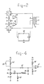
- Figure 2 shows the manner in which the final stage is preferably supplied.
- Figure 2 shows only some of the components from Figure 1, viz. the two converters 1 and 2 and the resistors 5 and 6.
- Figure 2 further shows a controllable supply unit 42 whose negative terminal is in this case connected to earth and whose positive terminal is connected to a centre tapping of the primary winding 3 of the transformer 4.
- the control terminal of the supply unit 42 is connected to the outputs of two comparators 43 and 44.
- One input of the two comparators 43 and 44 is connected to one pole of a reference voltage source 45, whose other pole is earthed.
- the other inputs of the two comparators 43 and 44 are connected to the respective current outputs of the converters 1 and 2 in the manner shown in Figure 2.
- the comparators 43 and 44 deliver a control signal to the voltage regulator 42 depending on the sum of the voltage across the resistor 5 and the reference voltage source 45, or the resistor 6 and the reference voltage source 45 respectively. If the sum of these voltages increases, a higher current therefore has to be supplied by the converter concerned and the voltage on the centre tapping of the primary winding 3 must preferably become higher in order to compensate for the voltage loss of the resistor 5 or 6 and any internal voltage losses in the converters.
- the output voltage of the regulator 42 which is fed to the centre tapping of the winding 3, therefore increases as more current is demanded. This achieves the result that the dissipation in the two converters 1 and 2 can be kept relatively low and virtually constant.
- the transformer 4 is preferably so constructed that this transformer becomes saturated at a predetermined current level, as a result of which a further increase in current is limited and an additional protection is consequently created.
- FIG 3 shows another embodiment of the apparatus according to the invention. Components which are also used in the embodiment according to Figure 1 are provided with the same reference symbols. The most important difference between the embodiments of Figures 1 and 3 is to be found in the circuit around the adjustment unit 17.
- the adjustment unit 17 is provided with a potentiometer 44 which is connected in series with a fixed resistor 42 between a fixed voltage terminal Vs and earth. The junction between the resistors 42 and the potentiometer 44 is connected to one input of a further comparator 41 whose other input is connected to a reference voltage source 43.
- Figure 4 shows a more detailed and further developed embodiment of the circuit around the potentiometer 44 in the amplitude adjustment unit 17.
- the circuit in Figure 4 again comprises the potentiometer 44 having the terminal contacts P1, P2 and P3, and the resistor 42 which is connected in series with the potentiometer 44 between the fixed voltage terminal Vs and earth. Furthermore, the slider of the resistor 44 is loaded by a slider loading resistor 45. The voltage at the junction between the resistor 42 and the potentiometer 44 is fed via a resistor 46 to one input of the comparator 41. The reference voltage, which has to be fed to the other input of the comparator 41, is obtained via a voltage divider comprising the resistors 47 and 48 fitted between earth and a fixed reference potential Vr. Finally, the said first input of the comparator 41 is furthermore decoupled via a capacitor 49. A switch 50 is furthermore fitted in parallel with the resistor 42 for test purposes.
- the circuit from Figure 4 provides a high degree of protection even in the unlikely event of one of the terminals P1, P2 or P3 of the potentiometer becoming detached or of any other defects occurring in the circuit, as is evident from the following analysis.
- the regulating voltage V regel also becomes zero as a result of the presence of the slider load resistor 45. In this case, too, no dangerous situation arises for the patient.
- the test switch 50 can be used to check the satisfactory operation of the comparator 41. If the switch 50 is depressed, the voltage at the junction between the resistor 42 and the potentiometer 44 will increase as a result thereof to the potential of the fixed voltage terminal Vs.
- the comparator 41 of necessity responds thereto by operating the protective relay and opening the contacts 8 and 9, and this can be checked in a simple manner.
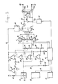
- Figure 5 shows yet another, further developed embodiment of the apparatus according to the invention.
- a microprocessor which, on the one hand, delivers control signals to the waveform generator 16, but is essentially used for test purposes, as will be further discussed briefly below.
- the components in Figure 5 which correspond to components from Figure 3 are indicated by the same reference numerals.
- the waveform generator 16 is provided internally with a chopper 51, a digital/analogue converter 52 and a waveform table memory 53.
- the amplitude adjustment signal originating from the adjustment unit 17 is converted by the converter 52 into a signal of predetermined level intended for controlling the converters 1 and 2. This signal is alternately presented via the chopper 51 to the converters 1 and 2.
- the desired waveform of the output signal is set by means of a correct choice of one of the waveforms stored in the memory 53. This choice is made by means of the adjustment unit 18 which generates via the microprocessor 54 a control signal for the waveform generator 16. Since the detailed operation of the waveform generator 16 is not relevant in relation to the invention, a more detailed description of the waveform generator 16 is considered superfluous. However, in relation to a detailed elaboration of this generator, attention is drawn to the literature from which diverse waveform generators constructed with the aid of digital/analogue converters and choppers are known.
- microprocessor 54 has the important task of testing the entire apparatus. A possible test procedure will be briefly discussed below.
- the self-testing of the apparatus starts. After the appearance of the supply voltage, the apparatus is in a safe initial stage. The user of the apparatus must not operate any of the adjustment devices of the apparatus during the self-testing and, moreover, the adjustment unit must be in the zero position.
- the microprocessor 54 checks this regularly and regards any deviations from these requirements as a fault, the response to which is as will be further described below.
- the microprocessor 54 carries out the following operations in succession:
- test cycle stops and a fault message is delivered via the indicating unit 19.
- the apparatus cannot be operated further and has to be switched off completely before a new attempt can be undertaken.
- the operation of the microprocessor 54 is found to be in order, the operation of the protective relay 10 and of the short-circuit relay 12 is then tested. In this case, a patient must not be connected.
- the test is carried out by presenting a known voltage to the input of the A/D converter (corresponding to a predetermined setting of the adjustment unit 17) as a result of which a predetermined current will start to flow through the output circuit if the output circuit is not open-circuit (the contacts 8 and 9 are closed).
- the A/D converter is then set to a level which corresponds to a value higher than the maximum permissible output current. The result thereof must be that the protective relay switches. The reason is that on switching on the apparatus the amplitude adjustment unit 17 must be at zero so that the protective relay 10 must come into operation directly on carrying out this test.
Abstract
Description
- The invention relates to an electrotherapy apparatus which is capable of generating direct currents or alternating currents which can be applied to a patient via electrodes.
- Such apparatuses are, for example, known from EP-0,054,654, EP-0,026,034 and DE-3,701,473. In particular, the last-mentioned publication describes a protective circuit with which a short circuit can be brought about between the electrodes with the aid of a photosensitive triac circuit in order to avoid undesirable high current peaks which may be painful or dangerous for a patient occurring in the output circuit on switching the apparatus on or off or in the event of mains supply failures. The triac circuit mentioned is controlled by a detector circuit which monitors the supply voltage of the apparatus.
- The object of the invention is now to provide an electrotherapy apparatus of this type with a much more extensive protection so that, even during normal operation and regardless of any mains voltage variations, the current which is applied to the patient is monitored and if necessary, is reduced if the current should exceed a predetermined value.
- Within the framework of this object, the invention now provides an electrotherapy apparatus which comprises:
- two voltage/current converters, each provided with a current input, a current output and a control voltage input, the current input of each of these converters being connected via a resistor to a first supply voltage terminal and the control voltage input being connected to a waveform generator,
- a transformer having a primary and a secondary winding, which secondary winding is connected via at least one relay contact to an output circuit which can be connected to the said electrodes, the two ends of the primary winding each being connected to a current output of one of the said converters and a centre tapping of the primary winding being connected to the second supply voltage terminal,
there being connected to the two said resistors a protective circuit which monitors the current through said resistors during operation and which, if a predetermined parameter of said current is exceeded, operates a relay, as a result of which the said at least one relay contact is switched over and the connection between the output circuit and the secondary winding of the transformer is interrupted. - In the apparatus according to the invention, the current delivered by each voltage/current converter to the primary winding of the transformer also flows through the resistor which is connected between the current input of the converter concerned and the first supply voltage terminal. As a result, therefore, of monitoring the current through this resistor, the current through the primary winding of the transformer is also monitored, as also is the currrent associated therewith through the secondary winding of the transformer to the electrodes.
- In addition, due to the use of a transformer, a direct galvanic coupling between the suppply voltage terminal and of the apparatus and the patient is avoided. As a result of using a bridge rectifier connected to the secondary side of the transformer, it is possible to feed not only alternating currents, but also direct currents to a patient via the electrodes.
- The current through the said resistors may be monitored in various ways. According to a first preferred embodiment, the protective circuit is provided with a first and a second comparator, each having an input connected to the junction between one of the said resistors and the current input connected thereto, and each having the other input connected, or connectable, to a reference voltage source in a manner such that, during operation, the voltage across each of the said resistors is compared in a comparator with a predetermined reference voltage and that, if the reference voltage is exceeded, the comparator concerned generates an energizing signal for the said relay. The reference voltage is preferably derived from adjustment means with which the user of the apparatus can set the desired output current. The first and second comparator then ensure that the voltage across the said resistors never exceeds, for example, 150% of the voltage across it if the set output current flows through said resistors.
- In a further embodiment of the apparatus, the protective apparatus is provided with a third comparator, one input of which is connected via a resistor network to the said resistors and the other input of which is connected, or is connectable, to a limit voltage source in a manner such that, during operation, the sum of the voltages across the said resistors is compared in the third comparator with a predetermined limit value, the third comparator generating an energizing signal for the said relay if the limit value is exceeded. This third comparator therefore ensures that, regardless of the set reference value, the output current never exceeds a predetermined limit value which can be specified on the basis of safety regulations, approval requirements and the like and which can, for example, be permanently set by the manufacturer of the apparatus.
- In general, it will be desirable that the said limit value is dependent on the instantaneous frequency. According to a preferred embodiment, therefore, the limit voltage source is provided with a frequency-dependent network such that the instantaneous limit value is dependent on the instantaneous frequency of the sum of the currents through the said resistors.
- Not only the amplitude of the current pulses which are delivered to the transformer by the voltage/current converters has an effect on the total current level on the secondary side, but the shape of the current pulses may also have an effect. In particular, an increasing width of the current pulses is of importance in that case. In connection therewith, in a further preferred embodiment, the protective circuit is provided with a fourth comparator, one input of which is connected via an integrating network to the junction between one of the said resistors and the associated current input and the other input of which is connected to a standard voltage source in a manner such that, during operation, the integrated voltage across the said one resistor concerned is compared with the standard voltage and that, if the standard voltage is exceeded, an energizing signal is generated by the fourth comparator for the said relay.
- The invention will be explained in more detail below with reference to the accompanying figures.
- Figure 1 shows a block diagram of the electrotherapy apparatus according to the invention.
- Figure 2 shows, in a block diagram, how the current/voltage converters in the apparatus in Figure 1 are supplied.
- Figure 3 shows another embodiment of the appparatus according to the invention.
- Figure 4 illustrates a detailed embodiment of the amplitude adjustment circuit in Figure 3.
- Figure 5 shows a further embodiment of an apparatus according to the invention.
- The electrotherapy apparatus shown diagrammatically in Figure 1 comprises two voltage/current converters 1 and 2, each provided with a
current input 1a, 2a, acurrent output control input 1c, 2c. Thecurrent outputs primary winding 3 of an output transformer 4. Thisprimary winding 3 is further provided with a centre tapping which is connected to a first (in this case the positive) supply voltage terminal. Thecurrent inputs 1a and 2a are each connected via aresistor resistors - The output winding 7 of the transformer is connected via two
relay contacts relay 10 to an output circuit comprising anindicator lamp 11, a short-circuit relay 12 having short-circuiting relay contacts 12a, abridge rectifier 14 and the mutually coupled three-position switches - The
control voltage inputs 1c, 2c of the converters 1 and 2 are connected to outputs of awaveform generator 16 which generates pulse voltages for controlling the two converters 1 and 2 on the basis of control signals originating from anamplitude adjustment circuit 17 and a currentform selection circuit 18. Information on the operation and the adjustment of thewaveform generator 16 may be rendered visible, if necessary, on adisplay unit 19. - The pulse-type control voltages delivered by the
waveform generator 16 control the two voltage/current converters 1 and 2 alternately in a manner such that an alternating current of predetermined level and predetermined frequency related to the level and the frequency of the pulse-type control voltage starts to flow in theprimary winding 3 of the transformer 4. As a consequence of this, a current of predetermined level (depending on the turns ratio) and a frequency corresponding to the frequency on the primary side is also induced in the output winding 7. If theswitches 15a/15b are set to the lowermost position, this output current can be fed from the secondary winding 7 via the closedrelay contacts output terminals output terminals switches 15a/15b are set to the position shown or to the central position so that either a positive or a negative rectified current is presented to theoutput terminals - Most of the components in Figure 1 which have still not been discussed until now form part of a protective circuit which serves to cause a
relay 10 to switch over when a predetermined current parameter is exceeded and consequently to open thecontacts - As shown in Figure 1, the voltage across the
resistor 5 is compared in acomparator 20 with the amplitude which is fixed by the user with a diagrammatically shownadjustment unit 17. In its simplest embodiment, this adjustment unit comprises a potentiometer whose intrinsic resistor is connected between a fixed voltage Vs and earth, while the adjustment voltage is tapped off via the slider. If the difference between the two voltages becomes larger than a predetermined limit value, thecomparator 20 delivers an output signal via theconductor 21 to therelay 10, as a result of which said relay will be operated and the normally closedcontacts - In a similar manner, the voltage across the
resistor 6 is compared in thecomparator 22 with the amplitude set with the aid of theamplitude adjustment unit 17. Here too, if the difference between the two voltages becomes larger than a predetermined limit value, thecomparator 22 will deliver an output signal via theconductor 21 to therelay 10, as a result of which said relay is operated and the normally closedcontacts - The level of the current which has to be fed to the patient via the
outputs amplitude adjustment unit 17. Depending on various factors, this current level will have to be relatively low in one case and set to a relatively high value in another case. Irrespective of the setting, however, this current level, viewed as a percentage, will not be allowed to exceed a predetermined limit value. The said abovementioned predetermined limit value may, for example, be equal to 150%. That is to say, if the voltage across one of theresistors adjustment unit 17, therelay 10 is operated and the output circuit is decoupled. Depending on the requirements which are imposed on the apparatus, another value can, of course, be chosen for this value of 150%. As will be known to a person skilled in the art, the percentage limit value may be set with the aid of suitable adjustment means for the comparators. This adjustment may either be fixed and be carried out in the factory, or may be capable of adjustment by the user within certain limits. - It is not only the voltages across the
resistors primary winding 3 of the transformer 4 which are monitored, but also the sum of the two currents is monitored in order to prevent the total output current exceeding a predetermined limit value which must not be exceeded under any circumstances regardless of the setting of the amplitude adjustment unit. This monitoring is carried out by means of theresistors resistors resistors resistors resistors comparator 25 whose other input receives a fixed adjustable voltage originating from asource 26. Thecomparator 25 compares the voltage at the junction between theresistors reference source 26 and delivers an output signal to theconductor 21 if the voltage at the junction between theresistors source 26. In that case, too, therelay 10 is thus operated and the output circuit is decoupled. It will be clear that this limit value which must not be exceeded is preferably permanently set so that neither the user nor the patient is able to exert any influence thereon. - Preferably the comparator has an adjustable frequency characteristic so that the instantaneous limit value depends on the instantaneous frequency of the current through the converters 1 and 2.
- Finally, the apparatus in Figure 1 comprises a
comparator 27 with which the voltage at the junction of aresistor 28 and acapacitor 29 is compared with the voltage originating from areference voltage source 30. It will be clear that the voltage across thecapacitor 29 will rise as the current pulses through theresistor 6 become wider. If the current pulses become too wide, then thecomparator 27 will respond and deliver via theconductor 21 an output signal to therelay 10, as a result of which the output circuit is decoupled. This prevents the possibility that, despite a constant primary current level, a change in the secondary current level is produced because the shape of the primary current pulses changes. - If necessary, a similar detection circuit may also be connected to
resistor 5, but this is not indicated in the figure. - Although mention is made in the above of "operating" the
relay 10, it is preferable to incorporate therelay 10 in the circuit in a manner such that the relay is energized under normal circumstances, in which state thecontacts contacts - Any relay operating signal on the
conductor 21 is also fed to thewaveform generator 16 via theresistor 31. This responds thereto by energizing a short-circuit relay 12 so that thecontacts 12a thereof are closed and the output voltage actually becomes 0 volt. As a result of this any current peaks from the transformer 7 are short-circuited if therelay 10 has still not been operated (released) and thecontacts contacts - The operation of the circuit described above is as follows. The desired current level is set by the user of the circuit or by the patient with the aid of the
adjustment unit 17. A choice is made between direct current and alternating current with the aid of theswitches adjustment unit 18, that is to say, the frequency of the pulses and the duty ratio. The resultant adjustment signals of theamplitude adjustment unit 17 and of the pulseshape adjustment unit 18 are fed to thewaveform generator 16 via theconductor 37, in which theresistor 38 is incorporated, or via theconductor 36. If a direct current is chosen, it is preferable that the duty ratio of the pulses generated is equal to 50% so that the ripple in the rectified current at the secondary side is at least approximately equal to zero. In order to achieve that, a coupling could be provided between theswitches 15a/15b and theadjustment unit 18. - Regardless of the choice between direct current or alternating current, pulse-type control signals are generated by the
waveform generator 16 for the voltage/current converters 1 and 2. If direct current has to be presented to theoutput terminals waveform generator 16, current pulses which are transmitted via the transformer 4 to the output circuit, these current pulses are rectified in therectifier 14 to produce a direct current, which direct current is delivered via theswitches output terminals - The polarity of the direct current to be delivered can be chosen by a correct choice of the position of the
switches - If alternating current pulses have to be delivered to the
output terminals switches conductors terminals - With the aid of the
indicator lamp 11 it is possible to check whether current is actually flowing through the output circuit and the load (patient) connected thereto. - If, for any reason whatsoever, the current through one of the
resistors 5 and 6 (and consequently, also the current which is fed to theoutput terminals 39 and 40) becomes so high that the percentage limit value is exceeded, at least one of thecomparators relay 10 will be operated. If the sum of the two currents exceeds an absolute limit value, thecomparator 25 will respond and operate therelay 10. If, for any reason whatsoever, the pulse shape is altered in a manner such that this results in too high a current level, thecomparator 27 will respond and energize therelay 10. In all these cases, the short-circuit relay 12 will also be operated. - Figure 2 shows the manner in which the final stage is preferably supplied. Figure 2 shows only some of the components from Figure 1, viz. the two converters 1 and 2 and the
resistors controllable supply unit 42 whose negative terminal is in this case connected to earth and whose positive terminal is connected to a centre tapping of the primary winding 3 of the transformer 4. The control terminal of thesupply unit 42 is connected to the outputs of twocomparators comparators reference voltage source 45, whose other pole is earthed. The other inputs of the twocomparators - The
comparators voltage regulator 42 depending on the sum of the voltage across theresistor 5 and thereference voltage source 45, or theresistor 6 and thereference voltage source 45 respectively. If the sum of these voltages increases, a higher current therefore has to be supplied by the converter concerned and the voltage on the centre tapping of the primary winding 3 must preferably become higher in order to compensate for the voltage loss of theresistor regulator 42, which is fed to the centre tapping of the winding 3, therefore increases as more current is demanded. This achieves the result that the dissipation in the two converters 1 and 2 can be kept relatively low and virtually constant. - The transformer 4 is preferably so constructed that this transformer becomes saturated at a predetermined current level, as a result of which a further increase in current is limited and an additional protection is consequently created.
- Figure 3 shows another embodiment of the apparatus according to the invention. Components which are also used in the embodiment according to Figure 1 are provided with the same reference symbols. The most important difference between the embodiments of Figures 1 and 3 is to be found in the circuit around the
adjustment unit 17. In Figure 3, theadjustment unit 17 is provided with apotentiometer 44 which is connected in series with a fixedresistor 42 between a fixed voltage terminal Vs and earth. The junction between theresistors 42 and thepotentiometer 44 is connected to one input of afurther comparator 41 whose other input is connected to areference voltage source 43. - With the aid of the
comparator 41, a check is made on whether the voltage at the junction between theresistor 42 and thepotentiometer 44 has a value which is lower than the fixed voltage Vs by at least a predetermined value. In the normal case this has to be so. However, should the connection between earth and thepotentiometer 44 become detached for any reason whatsoever, the voltage on the slider of thepotentiometer 44, and consequently the control voltage on one input of thecomparators comparators comparators resistor 42 in combination with thecomparator 41. In the normal case the voltage at the junction between theresistor 42 and thepotentiometer 44 will never exceed a certain value which is related to the dimensioning of theresistors potentiometer 44. However, if the connection between thepotentiometer 44 and earth becomes detached, the potential at the junction between theresistor 42 and thepotentiometer 44 will increase in a manner such that thecomparator 41 detects an increase above the set limit value. As a result thereof, thecomparator 41 delivers a signal which operates therelay 10 so that thecontacts - Figure 4 shows a more detailed and further developed embodiment of the circuit around the
potentiometer 44 in theamplitude adjustment unit 17. - The circuit in Figure 4 again comprises the
potentiometer 44 having the terminal contacts P1, P2 and P3, and theresistor 42 which is connected in series with thepotentiometer 44 between the fixed voltage terminal Vs and earth. Furthermore, the slider of theresistor 44 is loaded by aslider loading resistor 45. The voltage at the junction between theresistor 42 and thepotentiometer 44 is fed via aresistor 46 to one input of thecomparator 41. The reference voltage, which has to be fed to the other input of thecomparator 41, is obtained via a voltage divider comprising theresistors 47 and 48 fitted between earth and a fixed reference potential Vr. Finally, the said first input of thecomparator 41 is furthermore decoupled via acapacitor 49. A switch 50 is furthermore fitted in parallel with theresistor 42 for test purposes. - The circuit from Figure 4 provides a high degree of protection even in the unlikely event of one of the terminals P1, P2 or P3 of the potentiometer becoming detached or of any other defects occurring in the circuit, as is evident from the following analysis.
- If the connection at the position of the potentiometer terminal P1 should become detached, the regulating voltage Vr which is fed both to the
waveform generator 16 and to thecomparators - If the slider terminal becomes detached, the regulating voltage Vregel also becomes zero as a result of the presence of the
slider load resistor 45. In this case, too, no dangerous situation arises for the patient. - If the earth terminal P3 of the potentiometer should become detached, an excessive increase in voltage at the junction between the
resistors protective relay 10. - The test switch 50 can be used to check the satisfactory operation of the
comparator 41. If the switch 50 is depressed, the voltage at the junction between theresistor 42 and thepotentiometer 44 will increase as a result thereof to the potential of the fixed voltage terminal Vs. Thecomparator 41 of necessity responds thereto by operating the protective relay and opening thecontacts - Finally, Figure 5 shows yet another, further developed embodiment of the apparatus according to the invention. The difference between the embodiments of Figures 3 and 5 is that in Figure 5 a microprocessor is used which, on the one hand, delivers control signals to the
waveform generator 16, but is essentially used for test purposes, as will be further discussed briefly below. The components in Figure 5 which correspond to components from Figure 3 are indicated by the same reference numerals. - The
waveform generator 16 is provided internally with achopper 51, a digital/analogue converter 52 and awaveform table memory 53. The amplitude adjustment signal originating from theadjustment unit 17 is converted by theconverter 52 into a signal of predetermined level intended for controlling the converters 1 and 2. This signal is alternately presented via thechopper 51 to the converters 1 and 2. The desired waveform of the output signal is set by means of a correct choice of one of the waveforms stored in thememory 53. This choice is made by means of theadjustment unit 18 which generates via the microprocessor 54 a control signal for thewaveform generator 16. Since the detailed operation of thewaveform generator 16 is not relevant in relation to the invention, a more detailed description of thewaveform generator 16 is considered superfluous. However, in relation to a detailed elaboration of this generator, attention is drawn to the literature from which diverse waveform generators constructed with the aid of digital/analogue converters and choppers are known. - As has already been pointed out, the
microprocessor 54 has the important task of testing the entire apparatus. A possible test procedure will be briefly discussed below. - As soon as the supply voltage has reached its stable final value, the self-testing of the apparatus starts. After the appearance of the supply voltage, the apparatus is in a safe initial stage. The user of the apparatus must not operate any of the adjustment devices of the apparatus during the self-testing and, moreover, the adjustment unit must be in the zero position. The
microprocessor 54 checks this regularly and regards any deviations from these requirements as a fault, the response to which is as will be further described below. - First of all, under the control of a suitable program stored in the
microprocessor 54 for this purpose, themicroprocessor 54 carries out the following operations in succession: - 1. A check is made on whether the protective relay is switched off.
- 2. The registers of the microprocessor are checked internally. For this purpose, a register is filled with a particular bit pattern, said bit pattern is read out of the register again and then compared with the original bit pattern.
- 3. The arithmetic unit of the microprocessor is checked by carrying out a number of arithmetical instructions and comparing the calculated values with fixed correct values.
- 4. The program memory, and consequently also the address/databus of the processor, are checked by carrying out a check sum on the program memory and comparing the latter with a stored correct value.
- 5. The data memory of the microprocessor is checked by writing a predetermined bit pattern into the memory, reading out said bit pattern again and comparing it with the original bit pattern.
- 6. The time-determining units in the microprocessor are checked by allowing each unit to measure a predetermined period and comparing this period with the result generated with the aid of a delay loop which delays by the same period.
- 7. The
microprocessor 16 is provided with an analogue/digital converter which digitizes, in particular, the set value from theamplitude adjustment unit 17. A reference voltage is fed to this A/D converter as a test and the digitized result is compared with an expected correct value. - 8. The voltages at various points in the apparatus are measured by means of the A/D converter which has now been checked and checked with correct stored values.
- If a divergence is detected anywhere in this test procedure, or if an operating fault is detected, the test cycle stops and a fault message is delivered via the indicating
unit 19. The apparatus cannot be operated further and has to be switched off completely before a new attempt can be undertaken. - If the operation of the
microprocessor 54 is found to be in order, the operation of theprotective relay 10 and of the short-circuit relay 12 is then tested. In this case, a patient must not be connected. The test is carried out by presenting a known voltage to the input of the A/D converter (corresponding to a predetermined setting of the adjustment unit 17) as a result of which a predetermined current will start to flow through the output circuit if the output circuit is not open-circuit (thecontacts amplitude adjustment unit 17 must be at zero so that theprotective relay 10 must come into operation directly on carrying out this test. - The individual comparators which are incorporated in the protective circuit can be tested in a similar manner.
Claims (12)
- two voltage/current converters, each provided with a current input, a current output and a control voltage input, the current input of each of these converters being connected via a resistor to a first supply voltage terminal and the control voltage input being connected to a waveform generator,
- a transformer having a primary and a secondary winding, which secondary winding is connected via at least one relay contact to an output circuit which can be connected to the said electrodes, the two ends of the primary winding each being connected to a current output of one of the said converters and a centre tapping of the primary winding being connected to the second supply voltage terminal,
- there being connected to the two said resistors a protective circuit which monitors the current through said resistors during operation and which, if a predetermined parameter of said current is exceeded, operates a relay, as a result of which the said at least one relay contact is switched over and the connection between the output circuit and the secondary winding of the transformer is interrupted.
Priority Applications (1)
| Application Number | Priority Date | Filing Date | Title |
|---|---|---|---|
| AT89202704T ATE92777T1 (en) | 1988-10-31 | 1989-10-25 | ELECTROTHERAPY DEVICE. |
Applications Claiming Priority (2)
| Application Number | Priority Date | Filing Date | Title |
|---|---|---|---|
| NL8802670 | 1988-10-31 | ||
| NL8802670A NL8802670A (en) | 1988-10-31 | 1988-10-31 | ELECTROTHERAPY DEVICE. |
Publications (2)
| Publication Number | Publication Date |
|---|---|
| EP0367338A1 true EP0367338A1 (en) | 1990-05-09 |
| EP0367338B1 EP0367338B1 (en) | 1993-08-11 |
Family
ID=19853136
Family Applications (1)
| Application Number | Title | Priority Date | Filing Date |
|---|---|---|---|
| EP89202704A Expired - Lifetime EP0367338B1 (en) | 1988-10-31 | 1989-10-25 | Electrotherapy apparatus |
Country Status (5)
| Country | Link |
|---|---|
| EP (1) | EP0367338B1 (en) |
| AT (1) | ATE92777T1 (en) |
| DE (1) | DE68908342T2 (en) |
| ES (1) | ES2044068T3 (en) |
| NL (1) | NL8802670A (en) |
Cited By (5)
| Publication number | Priority date | Publication date | Assignee | Title |
|---|---|---|---|---|
| EP0459402A2 (en) * | 1990-05-29 | 1991-12-04 | Werner Dipl.-Ing. Kraus | Electro-medical apparatus for the production of a low-frequency magnetic field |
| EP0504835A2 (en) * | 1991-03-18 | 1992-09-23 | Friedrich Lauerer | Protection circuit for electromedical device |
| US9669212B2 (en) | 2005-04-19 | 2017-06-06 | Djo, Llc | Electrical stimulation device and method for therapeutic treatment and pain management |
| US9669211B2 (en) | 2007-02-13 | 2017-06-06 | Encore Medical Asset Corporation | Method and apparatus for applying neuromuscular electrical stimulation |
| US9808619B2 (en) | 2005-01-28 | 2017-11-07 | Encore Medical Asset Corporation | Independent protection system for an electrical muscle stimulation apparatus and method of using same |
Citations (7)
| Publication number | Priority date | Publication date | Assignee | Title |
|---|---|---|---|---|
| US3791373A (en) * | 1972-03-02 | 1974-02-12 | Univ Southern Illinois | Portable electroanesthesia device with automatic power control |
| DE2810046B1 (en) * | 1978-03-08 | 1979-06-07 | Siemens Ag | Method and device for measuring electrical currents and / or voltages in a plurality of current or voltage circuits |
| EP0026479A2 (en) * | 1979-09-27 | 1981-04-08 | Siemens Aktiengesellschaft | Electro-medical device |
| EP0026324A1 (en) * | 1979-08-31 | 1981-04-08 | Siemens Aktiengesellschaft | Electromedical stimulation-current device |
| FR2507900A1 (en) * | 1981-06-17 | 1982-12-24 | Faiveley Sa | Safety device for therapeutic electrology appts. - uses bistable memory and stops treatment in case of appts. fault and has alarm signal generator |
| US4600010A (en) * | 1984-10-04 | 1986-07-15 | Biolectron, Inc. | Electric stimulator and test instrument therefor |
| EP0269845A1 (en) * | 1986-11-07 | 1988-06-08 | Siemens Aktiengesellschaft | End amplifier for a stimulator |
-
1988
- 1988-10-31 NL NL8802670A patent/NL8802670A/en not_active Application Discontinuation
-
1989
- 1989-10-25 EP EP89202704A patent/EP0367338B1/en not_active Expired - Lifetime
- 1989-10-25 AT AT89202704T patent/ATE92777T1/en active
- 1989-10-25 DE DE89202704T patent/DE68908342T2/en not_active Expired - Fee Related
- 1989-10-25 ES ES89202704T patent/ES2044068T3/en not_active Expired - Lifetime
Patent Citations (7)
| Publication number | Priority date | Publication date | Assignee | Title |
|---|---|---|---|---|
| US3791373A (en) * | 1972-03-02 | 1974-02-12 | Univ Southern Illinois | Portable electroanesthesia device with automatic power control |
| DE2810046B1 (en) * | 1978-03-08 | 1979-06-07 | Siemens Ag | Method and device for measuring electrical currents and / or voltages in a plurality of current or voltage circuits |
| EP0026324A1 (en) * | 1979-08-31 | 1981-04-08 | Siemens Aktiengesellschaft | Electromedical stimulation-current device |
| EP0026479A2 (en) * | 1979-09-27 | 1981-04-08 | Siemens Aktiengesellschaft | Electro-medical device |
| FR2507900A1 (en) * | 1981-06-17 | 1982-12-24 | Faiveley Sa | Safety device for therapeutic electrology appts. - uses bistable memory and stops treatment in case of appts. fault and has alarm signal generator |
| US4600010A (en) * | 1984-10-04 | 1986-07-15 | Biolectron, Inc. | Electric stimulator and test instrument therefor |
| EP0269845A1 (en) * | 1986-11-07 | 1988-06-08 | Siemens Aktiengesellschaft | End amplifier for a stimulator |
Non-Patent Citations (1)
| Title |
|---|
| L'ONDE ELECTRIQUE, vol. 54, no. 8, 1974, pages 423-428; R.J. PLASZCZYNSKI: "Normes auxquelles doit répondre le matériel d'électronique médicale" * |
Cited By (9)
| Publication number | Priority date | Publication date | Assignee | Title |
|---|---|---|---|---|
| EP0459402A2 (en) * | 1990-05-29 | 1991-12-04 | Werner Dipl.-Ing. Kraus | Electro-medical apparatus for the production of a low-frequency magnetic field |
| EP0459402A3 (en) * | 1990-05-29 | 1992-06-03 | Werner Dipl.-Ing. Kraus | Electro-medical apparatus for the production of a low-frequency magnetic field |
| US5192263A (en) * | 1990-05-29 | 1993-03-09 | Werner Kraus | Electromedical apparatus for generating low-frequency magnetic fields |
| EP0504835A2 (en) * | 1991-03-18 | 1992-09-23 | Friedrich Lauerer | Protection circuit for electromedical device |
| EP0504835A3 (en) * | 1991-03-18 | 1993-05-05 | Friedrich Lauerer | Protection circuit for electromedical device |
| US9808619B2 (en) | 2005-01-28 | 2017-11-07 | Encore Medical Asset Corporation | Independent protection system for an electrical muscle stimulation apparatus and method of using same |
| US9669212B2 (en) | 2005-04-19 | 2017-06-06 | Djo, Llc | Electrical stimulation device and method for therapeutic treatment and pain management |
| US10328260B2 (en) | 2005-04-19 | 2019-06-25 | Djo, Llc | Electrical stimulation device and method for therapeutic treatment and pain management |
| US9669211B2 (en) | 2007-02-13 | 2017-06-06 | Encore Medical Asset Corporation | Method and apparatus for applying neuromuscular electrical stimulation |
Also Published As
| Publication number | Publication date |
|---|---|
| ES2044068T3 (en) | 1994-01-01 |
| DE68908342T2 (en) | 1994-02-24 |
| NL8802670A (en) | 1990-05-16 |
| EP0367338B1 (en) | 1993-08-11 |
| ATE92777T1 (en) | 1993-08-15 |
| DE68908342D1 (en) | 1993-09-16 |
Similar Documents
| Publication | Publication Date | Title |
|---|---|---|
| US5065083A (en) | Microprocessor controlled electronic stimulating device having a battery management system and method therefor | |
| US6047208A (en) | Iontophoretic controller | |
| JP4185123B2 (en) | Transfection control device sending high voltage current profile | |
| CA1270901A (en) | Power supply with battery backup | |
| US4037156A (en) | Power supply testing apparatus | |
| US6223077B1 (en) | Automatic power switching in a defibrillator | |
| US3947759A (en) | Leakage current monitoring system and method | |
| US6185458B1 (en) | Reduced energy self test operation in a defibrillator | |
| EP0367338B1 (en) | Electrotherapy apparatus | |
| US3916251A (en) | Filament current regulator for rotating anode X-ray tubes | |
| US4706674A (en) | Electrical stimulator for biological tissue utilizing output current monitor | |
| US4613850A (en) | Circuit arrangement for checking the position of electrodes | |
| JPH05137253A (en) | Abnormal voltage detector/controller | |
| US20230301715A1 (en) | Pulse ablation instrument and control method, control apparatus thereof, electronic device and medium | |
| JPH02133099A (en) | Trouble detectgor for ac generator | |
| US5471134A (en) | Measuring apparatus with adjustable indicator for measuring the real load factor on an electricity source | |
| GB2465581A (en) | Regulating and monitoring electrical output of a micro-current therapy device | |
| US4890002A (en) | Line voltage fault detector for appliance protection | |
| JP3055138B2 (en) | Battery charger | |
| US5470347A (en) | Safety monitor circuit for an ECT device and method | |
| Pepper et al. | An electric tooth pulp vitality tester | |
| US5221886A (en) | Device for regulating the battery charging voltage delivered by an alternator | |
| KR19990024700A (en) | Silicon controlled rectifier and gate pulse transformer tester | |
| CA2363105A1 (en) | Device for iontophoresis | |
| JP3446095B2 (en) | Low frequency treatment device |
Legal Events
| Date | Code | Title | Description |
|---|---|---|---|
| PUAI | Public reference made under article 153(3) epc to a published international application that has entered the european phase |
Free format text: ORIGINAL CODE: 0009012 |
|
| AK | Designated contracting states |
Kind code of ref document: A1 Designated state(s): AT BE CH DE ES FR GB IT LI NL |
|
| 17P | Request for examination filed |
Effective date: 19900607 |
|
| 17Q | First examination report despatched |
Effective date: 19920630 |
|
| GRAA | (expected) grant |
Free format text: ORIGINAL CODE: 0009210 |
|
| AK | Designated contracting states |
Kind code of ref document: B1 Designated state(s): AT BE CH DE ES FR GB IT LI NL |
|
| REF | Corresponds to: |
Ref document number: 92777 Country of ref document: AT Date of ref document: 19930815 Kind code of ref document: T |
|
| ITF | It: translation for a ep patent filed |
Owner name: JACOBACCI CASETTA & PERANI S.P.A. |
|
| REF | Corresponds to: |
Ref document number: 68908342 Country of ref document: DE Date of ref document: 19930916 |
|
| ET | Fr: translation filed | ||
| REG | Reference to a national code |
Ref country code: ES Ref legal event code: FG2A Ref document number: 2044068 Country of ref document: ES Kind code of ref document: T3 |
|
| PLBE | No opposition filed within time limit |
Free format text: ORIGINAL CODE: 0009261 |
|
| STAA | Information on the status of an ep patent application or granted ep patent |
Free format text: STATUS: NO OPPOSITION FILED WITHIN TIME LIMIT |
|
| 26N | No opposition filed | ||
| PGFP | Annual fee paid to national office [announced via postgrant information from national office to epo] |
Ref country code: GB Payment date: 19940920 Year of fee payment: 6 |
|
| PGFP | Annual fee paid to national office [announced via postgrant information from national office to epo] |
Ref country code: FR Payment date: 19941007 Year of fee payment: 6 |
|
| PGFP | Annual fee paid to national office [announced via postgrant information from national office to epo] |
Ref country code: BE Payment date: 19941011 Year of fee payment: 6 Ref country code: AT Payment date: 19941011 Year of fee payment: 6 |
|
| PGFP | Annual fee paid to national office [announced via postgrant information from national office to epo] |
Ref country code: ES Payment date: 19941019 Year of fee payment: 6 |
|
| PGFP | Annual fee paid to national office [announced via postgrant information from national office to epo] |
Ref country code: NL Payment date: 19941031 Year of fee payment: 6 |
|
| PGFP | Annual fee paid to national office [announced via postgrant information from national office to epo] |
Ref country code: DE Payment date: 19941104 Year of fee payment: 6 |
|
| PGFP | Annual fee paid to national office [announced via postgrant information from national office to epo] |
Ref country code: CH Payment date: 19941109 Year of fee payment: 6 |
|
| PG25 | Lapsed in a contracting state [announced via postgrant information from national office to epo] |
Ref country code: GB Effective date: 19951025 Ref country code: AT Effective date: 19951025 |
|
| PG25 | Lapsed in a contracting state [announced via postgrant information from national office to epo] |
Ref country code: ES Free format text: LAPSE BECAUSE OF THE APPLICANT RENOUNCES Effective date: 19951026 |
|
| PG25 | Lapsed in a contracting state [announced via postgrant information from national office to epo] |
Ref country code: LI Effective date: 19951031 Ref country code: CH Effective date: 19951031 Ref country code: BE Effective date: 19951031 |
|
| BERE | Be: lapsed |
Owner name: INGENIEURSBURO UNIPHY B.V. Effective date: 19951031 |
|
| PG25 | Lapsed in a contracting state [announced via postgrant information from national office to epo] |
Ref country code: NL Effective date: 19960501 |
|
| REG | Reference to a national code |
Ref country code: CH Ref legal event code: PL |
|
| GBPC | Gb: european patent ceased through non-payment of renewal fee |
Effective date: 19951025 |
|
| PG25 | Lapsed in a contracting state [announced via postgrant information from national office to epo] |
Ref country code: FR Effective date: 19960628 |
|
| PG25 | Lapsed in a contracting state [announced via postgrant information from national office to epo] |
Ref country code: DE Effective date: 19960702 |
|
| NLV4 | Nl: lapsed or anulled due to non-payment of the annual fee |
Effective date: 19960501 |
|
| REG | Reference to a national code |
Ref country code: FR Ref legal event code: ST |
|
| REG | Reference to a national code |
Ref country code: ES Ref legal event code: FD2A Effective date: 19991007 |
|
| PG25 | Lapsed in a contracting state [announced via postgrant information from national office to epo] |
Ref country code: IT Free format text: LAPSE BECAUSE OF NON-PAYMENT OF DUE FEES;WARNING: LAPSES OF ITALIAN PATENTS WITH EFFECTIVE DATE BEFORE 2007 MAY HAVE OCCURRED AT ANY TIME BEFORE 2007. THE CORRECT EFFECTIVE DATE MAY BE DIFFERENT FROM THE ONE RECORDED. Effective date: 20051025 |