EP0366945A1 - Femoral prosthesis with a set of fins - Google Patents
Femoral prosthesis with a set of fins Download PDFInfo
- Publication number
- EP0366945A1 EP0366945A1 EP89118184A EP89118184A EP0366945A1 EP 0366945 A1 EP0366945 A1 EP 0366945A1 EP 89118184 A EP89118184 A EP 89118184A EP 89118184 A EP89118184 A EP 89118184A EP 0366945 A1 EP0366945 A1 EP 0366945A1
- Authority
- EP
- European Patent Office
- Prior art keywords
- rib
- femoral prosthesis
- prosthesis according
- grooves
- shaft blade
- Prior art date
- Legal status (The legal status is an assumption and is not a legal conclusion. Google has not performed a legal analysis and makes no representation as to the accuracy of the status listed.)
- Granted
Links
Images


Classifications
-
- A—HUMAN NECESSITIES
- A61—MEDICAL OR VETERINARY SCIENCE; HYGIENE
- A61F—FILTERS IMPLANTABLE INTO BLOOD VESSELS; PROSTHESES; DEVICES PROVIDING PATENCY TO, OR PREVENTING COLLAPSING OF, TUBULAR STRUCTURES OF THE BODY, e.g. STENTS; ORTHOPAEDIC, NURSING OR CONTRACEPTIVE DEVICES; FOMENTATION; TREATMENT OR PROTECTION OF EYES OR EARS; BANDAGES, DRESSINGS OR ABSORBENT PADS; FIRST-AID KITS
- A61F2/00—Filters implantable into blood vessels; Prostheses, i.e. artificial substitutes or replacements for parts of the body; Appliances for connecting them with the body; Devices providing patency to, or preventing collapsing of, tubular structures of the body, e.g. stents
- A61F2/02—Prostheses implantable into the body
- A61F2/30—Joints
- A61F2/30721—Accessories
- A61F2/30734—Modular inserts, sleeves or augments, e.g. placed on proximal part of stem for fixation purposes or wedges for bridging a bone defect
-
- A—HUMAN NECESSITIES
- A61—MEDICAL OR VETERINARY SCIENCE; HYGIENE
- A61F—FILTERS IMPLANTABLE INTO BLOOD VESSELS; PROSTHESES; DEVICES PROVIDING PATENCY TO, OR PREVENTING COLLAPSING OF, TUBULAR STRUCTURES OF THE BODY, e.g. STENTS; ORTHOPAEDIC, NURSING OR CONTRACEPTIVE DEVICES; FOMENTATION; TREATMENT OR PROTECTION OF EYES OR EARS; BANDAGES, DRESSINGS OR ABSORBENT PADS; FIRST-AID KITS
- A61F2/00—Filters implantable into blood vessels; Prostheses, i.e. artificial substitutes or replacements for parts of the body; Appliances for connecting them with the body; Devices providing patency to, or preventing collapsing of, tubular structures of the body, e.g. stents
- A61F2/02—Prostheses implantable into the body
- A61F2/30—Joints
- A61F2/32—Joints for the hip
- A61F2/36—Femoral heads ; Femoral endoprostheses
-
- A—HUMAN NECESSITIES
- A61—MEDICAL OR VETERINARY SCIENCE; HYGIENE
- A61F—FILTERS IMPLANTABLE INTO BLOOD VESSELS; PROSTHESES; DEVICES PROVIDING PATENCY TO, OR PREVENTING COLLAPSING OF, TUBULAR STRUCTURES OF THE BODY, e.g. STENTS; ORTHOPAEDIC, NURSING OR CONTRACEPTIVE DEVICES; FOMENTATION; TREATMENT OR PROTECTION OF EYES OR EARS; BANDAGES, DRESSINGS OR ABSORBENT PADS; FIRST-AID KITS
- A61F2/00—Filters implantable into blood vessels; Prostheses, i.e. artificial substitutes or replacements for parts of the body; Appliances for connecting them with the body; Devices providing patency to, or preventing collapsing of, tubular structures of the body, e.g. stents
- A61F2/02—Prostheses implantable into the body
- A61F2/30—Joints
- A61F2/30721—Accessories
- A61F2/30724—Spacers for centering an implant in a bone cavity, e.g. in a cement-receiving cavity
-
- A—HUMAN NECESSITIES
- A61—MEDICAL OR VETERINARY SCIENCE; HYGIENE
- A61F—FILTERS IMPLANTABLE INTO BLOOD VESSELS; PROSTHESES; DEVICES PROVIDING PATENCY TO, OR PREVENTING COLLAPSING OF, TUBULAR STRUCTURES OF THE BODY, e.g. STENTS; ORTHOPAEDIC, NURSING OR CONTRACEPTIVE DEVICES; FOMENTATION; TREATMENT OR PROTECTION OF EYES OR EARS; BANDAGES, DRESSINGS OR ABSORBENT PADS; FIRST-AID KITS
- A61F2/00—Filters implantable into blood vessels; Prostheses, i.e. artificial substitutes or replacements for parts of the body; Appliances for connecting them with the body; Devices providing patency to, or preventing collapsing of, tubular structures of the body, e.g. stents
- A61F2/02—Prostheses implantable into the body
- A61F2/30—Joints
- A61F2/30721—Accessories
- A61F2/30739—Devices connected to the proximal part of an endoprosthetic femoral shaft for reinforcing or replacing the trochanters, e.g. the greater trochanter
-
- A—HUMAN NECESSITIES
- A61—MEDICAL OR VETERINARY SCIENCE; HYGIENE
- A61F—FILTERS IMPLANTABLE INTO BLOOD VESSELS; PROSTHESES; DEVICES PROVIDING PATENCY TO, OR PREVENTING COLLAPSING OF, TUBULAR STRUCTURES OF THE BODY, e.g. STENTS; ORTHOPAEDIC, NURSING OR CONTRACEPTIVE DEVICES; FOMENTATION; TREATMENT OR PROTECTION OF EYES OR EARS; BANDAGES, DRESSINGS OR ABSORBENT PADS; FIRST-AID KITS
- A61F2/00—Filters implantable into blood vessels; Prostheses, i.e. artificial substitutes or replacements for parts of the body; Appliances for connecting them with the body; Devices providing patency to, or preventing collapsing of, tubular structures of the body, e.g. stents
- A61F2/02—Prostheses implantable into the body
- A61F2/30—Joints
- A61F2/32—Joints for the hip
- A61F2/36—Femoral heads ; Femoral endoprostheses
- A61F2/3662—Femoral shafts
- A61F2/367—Proximal or metaphyseal parts of shafts
-
- A—HUMAN NECESSITIES
- A61—MEDICAL OR VETERINARY SCIENCE; HYGIENE
- A61F—FILTERS IMPLANTABLE INTO BLOOD VESSELS; PROSTHESES; DEVICES PROVIDING PATENCY TO, OR PREVENTING COLLAPSING OF, TUBULAR STRUCTURES OF THE BODY, e.g. STENTS; ORTHOPAEDIC, NURSING OR CONTRACEPTIVE DEVICES; FOMENTATION; TREATMENT OR PROTECTION OF EYES OR EARS; BANDAGES, DRESSINGS OR ABSORBENT PADS; FIRST-AID KITS
- A61F2/00—Filters implantable into blood vessels; Prostheses, i.e. artificial substitutes or replacements for parts of the body; Appliances for connecting them with the body; Devices providing patency to, or preventing collapsing of, tubular structures of the body, e.g. stents
- A61F2/02—Prostheses implantable into the body
- A61F2/30—Joints
- A61F2002/30001—Additional features of subject-matter classified in A61F2/28, A61F2/30 and subgroups thereof
- A61F2002/30108—Shapes
- A61F2002/3011—Cross-sections or two-dimensional shapes
- A61F2002/30138—Convex polygonal shapes
- A61F2002/30153—Convex polygonal shapes rectangular
-
- A—HUMAN NECESSITIES
- A61—MEDICAL OR VETERINARY SCIENCE; HYGIENE
- A61F—FILTERS IMPLANTABLE INTO BLOOD VESSELS; PROSTHESES; DEVICES PROVIDING PATENCY TO, OR PREVENTING COLLAPSING OF, TUBULAR STRUCTURES OF THE BODY, e.g. STENTS; ORTHOPAEDIC, NURSING OR CONTRACEPTIVE DEVICES; FOMENTATION; TREATMENT OR PROTECTION OF EYES OR EARS; BANDAGES, DRESSINGS OR ABSORBENT PADS; FIRST-AID KITS
- A61F2/00—Filters implantable into blood vessels; Prostheses, i.e. artificial substitutes or replacements for parts of the body; Appliances for connecting them with the body; Devices providing patency to, or preventing collapsing of, tubular structures of the body, e.g. stents
- A61F2/02—Prostheses implantable into the body
- A61F2/30—Joints
- A61F2002/30001—Additional features of subject-matter classified in A61F2/28, A61F2/30 and subgroups thereof
- A61F2002/30108—Shapes
- A61F2002/3011—Cross-sections or two-dimensional shapes
- A61F2002/30138—Convex polygonal shapes
- A61F2002/30158—Convex polygonal shapes trapezoidal
-
- A—HUMAN NECESSITIES
- A61—MEDICAL OR VETERINARY SCIENCE; HYGIENE
- A61F—FILTERS IMPLANTABLE INTO BLOOD VESSELS; PROSTHESES; DEVICES PROVIDING PATENCY TO, OR PREVENTING COLLAPSING OF, TUBULAR STRUCTURES OF THE BODY, e.g. STENTS; ORTHOPAEDIC, NURSING OR CONTRACEPTIVE DEVICES; FOMENTATION; TREATMENT OR PROTECTION OF EYES OR EARS; BANDAGES, DRESSINGS OR ABSORBENT PADS; FIRST-AID KITS
- A61F2/00—Filters implantable into blood vessels; Prostheses, i.e. artificial substitutes or replacements for parts of the body; Appliances for connecting them with the body; Devices providing patency to, or preventing collapsing of, tubular structures of the body, e.g. stents
- A61F2/02—Prostheses implantable into the body
- A61F2/30—Joints
- A61F2002/30001—Additional features of subject-matter classified in A61F2/28, A61F2/30 and subgroups thereof
- A61F2002/30316—The prosthesis having different structural features at different locations within the same prosthesis; Connections between prosthetic parts; Special structural features of bone or joint prostheses not otherwise provided for
- A61F2002/30329—Connections or couplings between prosthetic parts, e.g. between modular parts; Connecting elements
- A61F2002/30331—Connections or couplings between prosthetic parts, e.g. between modular parts; Connecting elements made by longitudinally pushing a protrusion into a complementarily-shaped recess, e.g. held by friction fit
-
- A—HUMAN NECESSITIES
- A61—MEDICAL OR VETERINARY SCIENCE; HYGIENE
- A61F—FILTERS IMPLANTABLE INTO BLOOD VESSELS; PROSTHESES; DEVICES PROVIDING PATENCY TO, OR PREVENTING COLLAPSING OF, TUBULAR STRUCTURES OF THE BODY, e.g. STENTS; ORTHOPAEDIC, NURSING OR CONTRACEPTIVE DEVICES; FOMENTATION; TREATMENT OR PROTECTION OF EYES OR EARS; BANDAGES, DRESSINGS OR ABSORBENT PADS; FIRST-AID KITS
- A61F2/00—Filters implantable into blood vessels; Prostheses, i.e. artificial substitutes or replacements for parts of the body; Appliances for connecting them with the body; Devices providing patency to, or preventing collapsing of, tubular structures of the body, e.g. stents
- A61F2/02—Prostheses implantable into the body
- A61F2/30—Joints
- A61F2002/30001—Additional features of subject-matter classified in A61F2/28, A61F2/30 and subgroups thereof
- A61F2002/30316—The prosthesis having different structural features at different locations within the same prosthesis; Connections between prosthetic parts; Special structural features of bone or joint prostheses not otherwise provided for
- A61F2002/30329—Connections or couplings between prosthetic parts, e.g. between modular parts; Connecting elements
- A61F2002/30383—Connections or couplings between prosthetic parts, e.g. between modular parts; Connecting elements made by laterally inserting a protrusion, e.g. a rib into a complementarily-shaped groove
- A61F2002/30387—Dovetail connection
-
- A—HUMAN NECESSITIES
- A61—MEDICAL OR VETERINARY SCIENCE; HYGIENE
- A61F—FILTERS IMPLANTABLE INTO BLOOD VESSELS; PROSTHESES; DEVICES PROVIDING PATENCY TO, OR PREVENTING COLLAPSING OF, TUBULAR STRUCTURES OF THE BODY, e.g. STENTS; ORTHOPAEDIC, NURSING OR CONTRACEPTIVE DEVICES; FOMENTATION; TREATMENT OR PROTECTION OF EYES OR EARS; BANDAGES, DRESSINGS OR ABSORBENT PADS; FIRST-AID KITS
- A61F2/00—Filters implantable into blood vessels; Prostheses, i.e. artificial substitutes or replacements for parts of the body; Appliances for connecting them with the body; Devices providing patency to, or preventing collapsing of, tubular structures of the body, e.g. stents
- A61F2/02—Prostheses implantable into the body
- A61F2/30—Joints
- A61F2002/30001—Additional features of subject-matter classified in A61F2/28, A61F2/30 and subgroups thereof
- A61F2002/30316—The prosthesis having different structural features at different locations within the same prosthesis; Connections between prosthetic parts; Special structural features of bone or joint prostheses not otherwise provided for
- A61F2002/30535—Special structural features of bone or joint prostheses not otherwise provided for
- A61F2002/30537—Special structural features of bone or joint prostheses not otherwise provided for adjustable
- A61F2002/3055—Special structural features of bone or joint prostheses not otherwise provided for adjustable for adjusting length
-
- A—HUMAN NECESSITIES
- A61—MEDICAL OR VETERINARY SCIENCE; HYGIENE
- A61F—FILTERS IMPLANTABLE INTO BLOOD VESSELS; PROSTHESES; DEVICES PROVIDING PATENCY TO, OR PREVENTING COLLAPSING OF, TUBULAR STRUCTURES OF THE BODY, e.g. STENTS; ORTHOPAEDIC, NURSING OR CONTRACEPTIVE DEVICES; FOMENTATION; TREATMENT OR PROTECTION OF EYES OR EARS; BANDAGES, DRESSINGS OR ABSORBENT PADS; FIRST-AID KITS
- A61F2/00—Filters implantable into blood vessels; Prostheses, i.e. artificial substitutes or replacements for parts of the body; Appliances for connecting them with the body; Devices providing patency to, or preventing collapsing of, tubular structures of the body, e.g. stents
- A61F2/02—Prostheses implantable into the body
- A61F2/30—Joints
- A61F2002/30001—Additional features of subject-matter classified in A61F2/28, A61F2/30 and subgroups thereof
- A61F2002/30316—The prosthesis having different structural features at different locations within the same prosthesis; Connections between prosthetic parts; Special structural features of bone or joint prostheses not otherwise provided for
- A61F2002/30535—Special structural features of bone or joint prostheses not otherwise provided for
- A61F2002/30561—Special structural features of bone or joint prostheses not otherwise provided for breakable or frangible
-
- A—HUMAN NECESSITIES
- A61—MEDICAL OR VETERINARY SCIENCE; HYGIENE
- A61F—FILTERS IMPLANTABLE INTO BLOOD VESSELS; PROSTHESES; DEVICES PROVIDING PATENCY TO, OR PREVENTING COLLAPSING OF, TUBULAR STRUCTURES OF THE BODY, e.g. STENTS; ORTHOPAEDIC, NURSING OR CONTRACEPTIVE DEVICES; FOMENTATION; TREATMENT OR PROTECTION OF EYES OR EARS; BANDAGES, DRESSINGS OR ABSORBENT PADS; FIRST-AID KITS
- A61F2/00—Filters implantable into blood vessels; Prostheses, i.e. artificial substitutes or replacements for parts of the body; Appliances for connecting them with the body; Devices providing patency to, or preventing collapsing of, tubular structures of the body, e.g. stents
- A61F2/02—Prostheses implantable into the body
- A61F2/30—Joints
- A61F2/30767—Special external or bone-contacting surface, e.g. coating for improving bone ingrowth
- A61F2/30771—Special external or bone-contacting surface, e.g. coating for improving bone ingrowth applied in original prostheses, e.g. holes or grooves
- A61F2002/3082—Grooves
- A61F2002/30823—Grooves having the shape of a reverse dovetail
-
- A—HUMAN NECESSITIES
- A61—MEDICAL OR VETERINARY SCIENCE; HYGIENE
- A61F—FILTERS IMPLANTABLE INTO BLOOD VESSELS; PROSTHESES; DEVICES PROVIDING PATENCY TO, OR PREVENTING COLLAPSING OF, TUBULAR STRUCTURES OF THE BODY, e.g. STENTS; ORTHOPAEDIC, NURSING OR CONTRACEPTIVE DEVICES; FOMENTATION; TREATMENT OR PROTECTION OF EYES OR EARS; BANDAGES, DRESSINGS OR ABSORBENT PADS; FIRST-AID KITS
- A61F2/00—Filters implantable into blood vessels; Prostheses, i.e. artificial substitutes or replacements for parts of the body; Appliances for connecting them with the body; Devices providing patency to, or preventing collapsing of, tubular structures of the body, e.g. stents
- A61F2/02—Prostheses implantable into the body
- A61F2/30—Joints
- A61F2/30767—Special external or bone-contacting surface, e.g. coating for improving bone ingrowth
- A61F2/30771—Special external or bone-contacting surface, e.g. coating for improving bone ingrowth applied in original prostheses, e.g. holes or grooves
- A61F2002/30878—Special external or bone-contacting surface, e.g. coating for improving bone ingrowth applied in original prostheses, e.g. holes or grooves with non-sharp protrusions, for instance contacting the bone for anchoring, e.g. keels, pegs, pins, posts, shanks, stems, struts
- A61F2002/30884—Fins or wings, e.g. longitudinal wings for preventing rotation within the bone cavity
-
- A—HUMAN NECESSITIES
- A61—MEDICAL OR VETERINARY SCIENCE; HYGIENE
- A61F—FILTERS IMPLANTABLE INTO BLOOD VESSELS; PROSTHESES; DEVICES PROVIDING PATENCY TO, OR PREVENTING COLLAPSING OF, TUBULAR STRUCTURES OF THE BODY, e.g. STENTS; ORTHOPAEDIC, NURSING OR CONTRACEPTIVE DEVICES; FOMENTATION; TREATMENT OR PROTECTION OF EYES OR EARS; BANDAGES, DRESSINGS OR ABSORBENT PADS; FIRST-AID KITS
- A61F2/00—Filters implantable into blood vessels; Prostheses, i.e. artificial substitutes or replacements for parts of the body; Appliances for connecting them with the body; Devices providing patency to, or preventing collapsing of, tubular structures of the body, e.g. stents
- A61F2/02—Prostheses implantable into the body
- A61F2/30—Joints
- A61F2/30767—Special external or bone-contacting surface, e.g. coating for improving bone ingrowth
- A61F2/30771—Special external or bone-contacting surface, e.g. coating for improving bone ingrowth applied in original prostheses, e.g. holes or grooves
- A61F2002/30878—Special external or bone-contacting surface, e.g. coating for improving bone ingrowth applied in original prostheses, e.g. holes or grooves with non-sharp protrusions, for instance contacting the bone for anchoring, e.g. keels, pegs, pins, posts, shanks, stems, struts
- A61F2002/30891—Plurality of protrusions
- A61F2002/30892—Plurality of protrusions parallel
-
- A—HUMAN NECESSITIES
- A61—MEDICAL OR VETERINARY SCIENCE; HYGIENE
- A61F—FILTERS IMPLANTABLE INTO BLOOD VESSELS; PROSTHESES; DEVICES PROVIDING PATENCY TO, OR PREVENTING COLLAPSING OF, TUBULAR STRUCTURES OF THE BODY, e.g. STENTS; ORTHOPAEDIC, NURSING OR CONTRACEPTIVE DEVICES; FOMENTATION; TREATMENT OR PROTECTION OF EYES OR EARS; BANDAGES, DRESSINGS OR ABSORBENT PADS; FIRST-AID KITS
- A61F2/00—Filters implantable into blood vessels; Prostheses, i.e. artificial substitutes or replacements for parts of the body; Appliances for connecting them with the body; Devices providing patency to, or preventing collapsing of, tubular structures of the body, e.g. stents
- A61F2/02—Prostheses implantable into the body
- A61F2/30—Joints
- A61F2/32—Joints for the hip
- A61F2/36—Femoral heads ; Femoral endoprostheses
- A61F2/3662—Femoral shafts
- A61F2002/3678—Geometrical features
- A61F2002/368—Geometrical features with lateral apertures, bores, holes or openings, e.g. for reducing the mass, for receiving fixation screws or for communicating with the inside of a hollow shaft
-
- A—HUMAN NECESSITIES
- A61—MEDICAL OR VETERINARY SCIENCE; HYGIENE
- A61F—FILTERS IMPLANTABLE INTO BLOOD VESSELS; PROSTHESES; DEVICES PROVIDING PATENCY TO, OR PREVENTING COLLAPSING OF, TUBULAR STRUCTURES OF THE BODY, e.g. STENTS; ORTHOPAEDIC, NURSING OR CONTRACEPTIVE DEVICES; FOMENTATION; TREATMENT OR PROTECTION OF EYES OR EARS; BANDAGES, DRESSINGS OR ABSORBENT PADS; FIRST-AID KITS
- A61F2/00—Filters implantable into blood vessels; Prostheses, i.e. artificial substitutes or replacements for parts of the body; Appliances for connecting them with the body; Devices providing patency to, or preventing collapsing of, tubular structures of the body, e.g. stents
- A61F2/02—Prostheses implantable into the body
- A61F2/30—Joints
- A61F2/32—Joints for the hip
- A61F2/36—Femoral heads ; Femoral endoprostheses
- A61F2/3662—Femoral shafts
- A61F2002/3678—Geometrical features
- A61F2002/369—Stepped shaft, i.e. having discrete diameter changes
-
- A—HUMAN NECESSITIES
- A61—MEDICAL OR VETERINARY SCIENCE; HYGIENE
- A61F—FILTERS IMPLANTABLE INTO BLOOD VESSELS; PROSTHESES; DEVICES PROVIDING PATENCY TO, OR PREVENTING COLLAPSING OF, TUBULAR STRUCTURES OF THE BODY, e.g. STENTS; ORTHOPAEDIC, NURSING OR CONTRACEPTIVE DEVICES; FOMENTATION; TREATMENT OR PROTECTION OF EYES OR EARS; BANDAGES, DRESSINGS OR ABSORBENT PADS; FIRST-AID KITS
- A61F2/00—Filters implantable into blood vessels; Prostheses, i.e. artificial substitutes or replacements for parts of the body; Appliances for connecting them with the body; Devices providing patency to, or preventing collapsing of, tubular structures of the body, e.g. stents
- A61F2/02—Prostheses implantable into the body
- A61F2/30—Joints
- A61F2/46—Special tools or methods for implanting or extracting artificial joints, accessories, bone grafts or substitutes, or particular adaptations therefor
- A61F2/4603—Special tools or methods for implanting or extracting artificial joints, accessories, bone grafts or substitutes, or particular adaptations therefor for insertion or extraction of endoprosthetic joints or of accessories thereof
- A61F2002/4619—Special tools or methods for implanting or extracting artificial joints, accessories, bone grafts or substitutes, or particular adaptations therefor for insertion or extraction of endoprosthetic joints or of accessories thereof for extraction
-
- A—HUMAN NECESSITIES
- A61—MEDICAL OR VETERINARY SCIENCE; HYGIENE
- A61F—FILTERS IMPLANTABLE INTO BLOOD VESSELS; PROSTHESES; DEVICES PROVIDING PATENCY TO, OR PREVENTING COLLAPSING OF, TUBULAR STRUCTURES OF THE BODY, e.g. STENTS; ORTHOPAEDIC, NURSING OR CONTRACEPTIVE DEVICES; FOMENTATION; TREATMENT OR PROTECTION OF EYES OR EARS; BANDAGES, DRESSINGS OR ABSORBENT PADS; FIRST-AID KITS
- A61F2220/00—Fixations or connections for prostheses classified in groups A61F2/00 - A61F2/26 or A61F2/82 or A61F9/00 or A61F11/00 or subgroups thereof
- A61F2220/0025—Connections or couplings between prosthetic parts, e.g. between modular parts; Connecting elements
- A61F2220/0033—Connections or couplings between prosthetic parts, e.g. between modular parts; Connecting elements made by longitudinally pushing a protrusion into a complementary-shaped recess, e.g. held by friction fit
-
- A—HUMAN NECESSITIES
- A61—MEDICAL OR VETERINARY SCIENCE; HYGIENE
- A61F—FILTERS IMPLANTABLE INTO BLOOD VESSELS; PROSTHESES; DEVICES PROVIDING PATENCY TO, OR PREVENTING COLLAPSING OF, TUBULAR STRUCTURES OF THE BODY, e.g. STENTS; ORTHOPAEDIC, NURSING OR CONTRACEPTIVE DEVICES; FOMENTATION; TREATMENT OR PROTECTION OF EYES OR EARS; BANDAGES, DRESSINGS OR ABSORBENT PADS; FIRST-AID KITS
- A61F2230/00—Geometry of prostheses classified in groups A61F2/00 - A61F2/26 or A61F2/82 or A61F9/00 or A61F11/00 or subgroups thereof
- A61F2230/0002—Two-dimensional shapes, e.g. cross-sections
- A61F2230/0017—Angular shapes
- A61F2230/0019—Angular shapes rectangular
-
- A—HUMAN NECESSITIES
- A61—MEDICAL OR VETERINARY SCIENCE; HYGIENE
- A61F—FILTERS IMPLANTABLE INTO BLOOD VESSELS; PROSTHESES; DEVICES PROVIDING PATENCY TO, OR PREVENTING COLLAPSING OF, TUBULAR STRUCTURES OF THE BODY, e.g. STENTS; ORTHOPAEDIC, NURSING OR CONTRACEPTIVE DEVICES; FOMENTATION; TREATMENT OR PROTECTION OF EYES OR EARS; BANDAGES, DRESSINGS OR ABSORBENT PADS; FIRST-AID KITS
- A61F2230/00—Geometry of prostheses classified in groups A61F2/00 - A61F2/26 or A61F2/82 or A61F9/00 or A61F11/00 or subgroups thereof
- A61F2230/0002—Two-dimensional shapes, e.g. cross-sections
- A61F2230/0017—Angular shapes
- A61F2230/0026—Angular shapes trapezoidal
Definitions
- the invention relates to a femoral prosthesis according to the preamble of claim 1.
- the known prostheses of the type mentioned at the outset have a transverse groove on each side of the shaft blade, which takes up the entire area near the neck.
- a flat rib part covering the entire width of the shaft blade and essentially having the height of the trochanter wing is inserted into these grooves.
- the rib parts have ribs running in the longitudinal direction of the shaft blade in order to enable the prosthesis to be anchored in a manner suitable for renewable bone tissue.
- the implantation cavity is prepared in accordance with the prosthesis cross section, one is carried out Finishing of the cavity walls with regard to the surface shape of the rib parts to be used. If the finishing is not completely successful, e.g. B. with regard to the inclination of the modeled cavity wall or due to locally excessive removal, the prosthesis cannot be fitted properly in the femur and only partially supports. As a result, local overloads or, in the long term, relocation of the implanted prosthesis can occur.
- the cavity once selected should remain essentially unchanged even when making corrections.
- the femoral prosthesis according to the invention has the characterizing features of claim 1.
- the individual rib parts can be selected for insertion into the prosthesis.
- the necessary adjustment of the cave wall can then be carried out locally, rib part by rib part, along the respective rib.
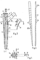
- Figures 1a and 1b show the shaft blade 1, which has a longitudinal axis 2 and extends from its distal end 3 over its length to a region 4 close to the neck.
- the medial narrow side 5 of the shaft blade 1 merges into a neck 6, which ends in a cone pin 7, which serves to receive a joint ball 8.
- the lateral side 9 of the shaft blade 1 widens to the trochanter wing 10; it essentially forms the late rale longitudinal side of the region near the neck 4.
- a cusp 12 is provided with a transverse bore 13, on which the hook of a tapping instrument can be attached.
- One side of the prosthesis 14 is congruent with the other side 15, so that the prosthesis can be used either in the right or left femur.
- grooves 16 In the region 3 of the shaft blade 1 near the neck, there are a plurality of grooves 16 into which rib parts 17 can be inserted.
- the grooves extend parallel to the longitudinal axis 2 of the shaft blade 1; its distal end 18 is at the level of the distal end of the trochanter wing 10. Its proximal end 19 opens into a shoulder 21 with which the cusp 11 is offset from the region 4 near the neck.
- a bore 22, which is described in more detail below, runs across the grooves 16 and serves to lock the rib elements 17.
- Another groove 23 parallel to the longitudinal axis 2 is provided in the trochanter wing 10 and has the same configuration, in particular an open end 19 opening into the shoulder 21, as the grooves 16.
- the prosthesis also includes a set of the rib parts 17, 17a for insertion into the grooves 16, 23.
- the rib parts 17, 17a are present in the set with ribs 24 of different heights, but each of the same design with a foot 25 having a notch 26.
- the rib parts 17 are intended to be inserted into the grooves 16, while the rib parts 17a in the rib 24 have a transverse notch 27 have and are therefore provided for insertion into the groove 23.
- the notches 26, 27 serve to lock the rib parts inserted into the grooves; they are described below together with the bore 22.
- the rib feet 25 have a dovetail profile which is opposite to the grooves 16, 23, so that rib parts which are inserted and locked into the grooves 16, 23 from the open end 19 remain firmly in place.
- the prosthesis with the shaft blade 1 is brought into the end position as far as possible in such a way that the rib parts 17, 17a can be selected from the set for fitting the region 4 close to the neck in the prepared implantation cavity in the end of the femur.
- the cavity wall is then modeled rib-by-rib until the prosthesis is properly fitted to the cavity wall by fully fitting all rib parts.
- FIG. 2 shows the corresponding arrangement with the aid of a cross section through the region 4 near the neck along the line I-I of FIG. 1a.
- Each bore 22 runs transversely on the side or on the side 14, intersecting the groove base 28 of the grooves 16. This creates a notch 28a in the groove bottom 28.
- the bores 22 open into a groove 29 which crosses the groove 23.
- This arrangement is intended for receiving a bracket 30 which, in the locked position, rests with its web 31 in the notch 27 of the rib part 17a, but with its legs 32 protrudes through the bores 22 and traverses the groove base 28 in the notches 28a.
- the prosthesis After the prosthesis is fitted into the cavity, it is lifted out a little and the rib elements 17, 17a locked by inserting the bracket 30. After the prosthesis has been reinserted into its end position, the position of the bracket 30 is also fixed, since the bone wall resting on the lateral side of the prosthesis 9 prevents the bracket 30 from sliding out of its locked position.
- the rib parts 17 can also have a notch 27, so that each rib part of the set can optionally be inserted into a groove 17 or a groove 23.
- the groove 23 can have a different width than the grooves 16, so that the rib parts 17, 17a cannot be confused.
- pins 32a which can be inserted into the respective bore 22, can be used instead of the bracket 30 to lock the rib elements 17.
- the grooves 16 extend practically over the entire length of the shaft blade 1 and have a rectangular profile (FIG. 4).
- the groove 23 on the lateral side 9 extends over the entire length of the shaft blade 1.
- the transition area between the medial narrow side 5 and the neck 6 has a relatively small curve radius.
- this prosthesis is assigned a set of spacers 35 which can be inserted into corresponding bores 38, 39 in the medial narrow side 5 by means of pins 36, 37.
- Fig. 3 it is indicated by dashed lines that the set of spacers 35 has three, for example.
- the rib parts 17 and 17a to be inserted into the grooves 16 and 23 are of identical design and are shown in FIG. 5. It can be seen from this that these rib parts 17 and 17a are of decreasing height towards the distal end 3 of the shaft blade, this height gradually decreasing. Notches 41 are present between adjacent sections 40 of constant height of the rib parts 17, 17a of FIG. 5, which form a predetermined breaking point.
- the curvature of the calcar arch is estimated in the prepared implantation cavity and the appropriate spacer 35 is inserted into the medial narrow side 5 of the shaft blade 1. Then the prosthesis (still without rib parts) is inserted into the implantation cavity. Now, rib parts 17 and 17a are hammered into the grooves 16 and 23, respectively, until the surgeon notices that the apex region of the rib parts 17 and 17a, which protrudes outwards, abuts the inner wall of the implantation cavity. Then it goes up protruding part of the rib parts 17 and 17a broken off at the nearest predetermined breaking point 41. If the resulting fracture still protrudes upwards, the rib part 17 or 17 a in question can be hammered in further until the upper end of the rib part is flush with the shoulder 21 at the upper end of the shaft blade 1.
- a cover part 42 is provided, as shown in FIG. 3, which is anchored by means of a screw bolt 43 on the shoulder 21 at the upper end of the shaft blade 1.
- the shoulder 21, as can be clearly seen in FIG. 3, is crossed by a groove 44 with a T-shaped profile.
- a threaded bore 45 for receiving the screw bolt 43 extends from the base of this groove 44.
- the groove 44 also serves, among other things, to pull the prosthesis (after the cover part 42 has been removed) out of the implantation cavity with a corresponding handle (not shown).
- the inventive design of the area near the neck is not limited to the prosthesis with a straight and symmetrical shaft blade shown as an example.
- the arrangement of grooves and matching rib parts shown is suitable for any prosthesis that must be anchored at the proximal end of the femur.
Abstract
Description
Die Erfindung betrifft eine Femurprothese nach dem Oberbegriff des Anspruches 1.The invention relates to a femoral prosthesis according to the preamble of
Bekannte Prothesen dieser Art werden z. B. im Diaphysenbereich mit dem distalen Ende des Schaftblatts verklemmt oder verkeilt und im proximalen Bereich des bearbeiteten Femurs verankert. Nachstehend wird auf die Verankerung im proximalen Bereich Bezug genommen.Known prostheses of this type are used for. B. in the diaphyseal area with the distal end of the shaft blade or wedged and anchored in the proximal area of the machined femur. The anchorage in the proximal region is referred to below.
Für die Verankerung besitzen die bekannten Prothesen der eingangs genannten Art auf jeder Seite des Schaftblattes eine den gesamten halsnahen Bereich einnehmende, querverlaufende Nut. In diese Nuten wird bei der Implantation zur Anpassung der Prothesendicke je ein flächiges, die ganze Breite des Schaftblatts überdeckendes und im wesentlichen die Höhe des Trochanterflügels besitzendes Rippenteil eingesetzt. Die Rippenteile besitzen in Längsrichtung des Schaftblatts verlaufende Rippen, um eine für nachwachsendes Knochengewebe geeignete Verankerung der Prothese zu ermöglichen.For anchoring, the known prostheses of the type mentioned at the outset have a transverse groove on each side of the shaft blade, which takes up the entire area near the neck. During the implantation to adjust the thickness of the prosthesis, a flat rib part covering the entire width of the shaft blade and essentially having the height of the trochanter wing is inserted into these grooves. The rib parts have ribs running in the longitudinal direction of the shaft blade in order to enable the prosthesis to be anchored in a manner suitable for renewable bone tissue.
Bei diesen Prothesen wird als nachteilig empfunden, dass trotz der im Satz mit verschiedener Dicke zur Verfügung stehenden Rippenteile eine einwandfreie Passung der Prothese in der Implantationshöhlung nur sehr schwer erreicht werden kann:It is perceived as a disadvantage of these prostheses that despite the rib parts available in the set with different thicknesses, it is very difficult to achieve a perfect fit of the prosthesis in the implantation cavity:
Sobald nämlich die Implantationshöhlung dem Prothesenquerschnitt entsprechend vorbereitet ist, erfolgt eine Feinbearbeitung der Höhlungswände im Hinblick auf die Oberflächenform der einzusetzenden Rippenteile. Gelingt die Feinbearbeitung nicht vollständig, z. B. bezüglich der Neigung der ausmodellierten Höhlungswand oder durch lokal überhöhten Abtrag, kann die Prothese im Femur nicht einwandfrei eingepasst werden und trägt nur teilweise. In der Folge können lokale Ueberbeanspruchungen oder längerfristig eine Verlagerung der implantierten Prothese entstehen.As soon as the implantation cavity is prepared in accordance with the prosthesis cross section, one is carried out Finishing of the cavity walls with regard to the surface shape of the rib parts to be used. If the finishing is not completely successful, e.g. B. with regard to the inclination of the modeled cavity wall or due to locally excessive removal, the prosthesis cannot be fitted properly in the femur and only partially supports. As a result, local overloads or, in the long term, relocation of the implanted prosthesis can occur.
Solch eine mangelhafte Passung ist zwar in der Regel durch eine Nachbearbeitung des Femurendes unter Verwendung eines nächstdickeren Rippenelementes korrigierbar. Dann stellt sich aber wieder dasselbe handwerkliche Problem; zudem ist besonders im Trochanterbereich wegen des Ansatzes von Muskeln und Bändern das Abtragen weiterer Knochensubstanz unerwünscht.Such a poor fit can generally be corrected by reworking the end of the femur using a thicker rib element. Then the same craft problem arises again; in addition, particularly in the trochanter area, the removal of further bone substance is undesirable because of the attachment of muscles and ligaments.
Entsprechend ist es die Aufgabe der vorliegenden Erfindung, eine Prothese zu schaffen, bei welcher eine schwierige und zeitraubende Anpassung der Implantationshöhlung entfällt und gleichzeitg einwandfreie Passung der Prothese durch vollständige Anlage aller Rippen an die Wände der Höhlung gewährleistet ist. Insbesondere soll die einmal gewählte Höhlung auch bei Korrekturen im wesentlichen erhalten bleiben.Accordingly, it is the object of the present invention to provide a prosthesis in which a difficult and time-consuming adaptation of the implantation cavity is eliminated and, at the same time, a perfect fit of the prosthesis is ensured by the complete abutment of all ribs on the walls of the cavity. In particular, the cavity once selected should remain essentially unchanged even when making corrections.
Zur Lösung dieser Aufgabe besitzt die erfindungsgemässe Femurprothese die kennzeichnenden Merkmale von Anspruch 1.To achieve this object, the femoral prosthesis according to the invention has the characterizing features of
Durch diese Anordnung wird erreicht, dass in einem Ar beitsgang von der dorsalen bzw. ventralen Höhlungswand nur noch ein lokaler, für die Feinbearbeitung günstig verlaufender Bereich gegengleich zum entsprechenden Prothesenteil modelliert werden muss:This arrangement ensures that in an Ar only a local area of the dorsal or ventral cavity wall, which runs favorably for fine machining, has to be modeled in relation to the corresponding prosthesis part:
Ausgehend von der nach dem Prothesenquerschnitt vorbereiteten Höhlung mit unregelmässig verlaufenden Wandbereichen können die einzelnen Rippenteile zum Einsetzen in die Prothese ausgewählt werden. Die notwendige Anpassung der Höhlenwand kann dann lokal, Rippenteil für Rippenteil, der jeweiligen Rippe entlang, vorgenommen werden.Starting from the cavity with irregular wall areas prepared according to the prosthesis cross section, the individual rib parts can be selected for insertion into the prosthesis. The necessary adjustment of the cave wall can then be carried out locally, rib part by rib part, along the respective rib.
Da ein Abmessen einer fertig zu modellierenden Wandfläche in die Tiefe und hinsichtlich Längsneigung weniger Schwierigkeiten bietet als bezüglich Breite und Querneigung, ist dies verhältnismässig einfach. Sollte trotzdem einmal zu viel Knochenmaterial abgetragen werden, kann das Rippenteil unter entspechender Nachbearbeitung gegen ein nächsthöheres ausgetauscht werden. Die Nachbearbeitung erfolgt dann wieder lokal, es ist nicht mehr notwendig, zur Korrektur die gesamte dorsale oder ventrale Höhlungswand abzutragen; der weitere Verlust an Knochenmatial hält sich in vertretbaren Grenzen.Since measuring a wall surface to be modeled in depth and with regard to longitudinal inclination is less difficult than with respect to width and transverse inclination, this is relatively simple. If too much bone material is nevertheless removed, the rib part can be exchanged for a next higher one with appropriate reworking. The post-processing then takes place locally again, it is no longer necessary to remove the entire dorsal or ventral cavity wall for correction; the further loss of bone material is within reasonable limits.
Bevorzugte Ausführungsformen weisen Merkmale der abhängigen Ansprüche auf.Preferred embodiments have features of the dependent claims.
Nachstehend sind Ausführungsbeispiele der vorgeschlagenen Femurprothese anhand der Figuren näher beschrieben. Es zeigt:
- Fig. 1a eine Ansicht der dorsalen bzw. ventralen Seite einer erfindungsgemässen Prothese mit einem zugehörigen Rippenteil;
- Fig. 1b eine laterale Ansicht der Prothese der Fig. 1 mit einem weiteren Rippenteil;
- Fig. 2 einen Schnitt durch den halsnahen Bereich der Prothese von Fig. 1 entlang der dort eingezeichneten Linie I-I mit Rippenteilen und diese verriegelnden Mitteln;
- Fig. 3 in auseinandergezogener Darstellung eine weitere Ausführungsform;
- Fig. 4 einen Schnitt längs der Linie IV-IV der Fig. 3 mit eingesetzten Rippenteilen; und
- Fig. 5 in Seiten- bzw. Frontansicht ein Rippenteil für die Prothese gemäss Fig. 3.
- 1a shows a view of the dorsal or ventral side of a prosthesis according to the invention with an associated rib part;
- 1b shows a lateral view of the prosthesis of FIG. 1 with a further rib part;
- FIG. 2 shows a section through the region of the prosthesis from FIG. 1 near the neck along line II drawn therein with rib parts and locking means;
- Figure 3 is an exploded view of another embodiment.
- FIG. 4 shows a section along the line IV-IV of FIG. 3 with inserted rib parts; and
- 5 shows a side or front view of a rib part for the prosthesis according to FIG. 3.
In den Figuren sind für sich funktionell entsprechende Bestandteile dieselben Bezugsziffern verwendet.The same reference numbers are used in the figures for functionally corresponding components.
Die Figuren 1a und 1b zeigen das Schaftblatt 1, welches eine Längsachse 2 besitzt und sich von seinem distalen Ende 3 über seine Länge zu einem halsnahen Bereich 4 erweitert. Die mediale Schmalseite 5 des Schaftblattes 1 geht in einen Hals 6 über, welcher in einem Konuszapfen 7 endet, der zur Aufnahme einer Gelenkkugel 8 dient. Die laterale Seite 9 des Schaftblattes 1 erweitert sich zum Trochanterflügel 10; er bildet im wesentlichen die late rale Längsseite des halsnahen Bereichs 4. Am proximalen Ende 11 der Prothese ist ein Höcker 12 mit einer Querbohrung 13 vorgesehen, an welcher der Haken eines Ausschlaginstruments angesetzt werden kann.Figures 1a and 1b show the
Die eine Prothesenseite 14 ist deckungsgleich zur anderen Seite 15 ausgestaltet, so dass die Prothese wahlweise im rechten oder linken Femur eingesetzt werden kann.One side of the
Im halsnahen Bereich 3 des Schaftblattes 1 sind mehrere Nuten 16 vorhanden, in welche Rippenteile 17 einsetzbar sind. Die Nuten erstrecken sich parallel zur Längsachse 2 des Schaftblattes 1; ihr distales Ende 18 befindet sich auf der Höhe des distalen Endes des Trochanterflügels 10. Ihr proximales Ende 19 mündet offen in eine Schulter 21, mit welcher der Höcker 11 vom halsnahen Bereich 4 abgesetzt ist. Quer zu den Nuten 16 verläuft eine weiter unten noch näher beschriebene Bohrung 22, welche der Verriegelung der Rippenelemente 17 dient.In the
Eine weitere, zur Längsachse 2 parallele Nut 23 ist im Trochanterflügel 10 vorgesehen und besitzt dieselbe Konfiguration, insbesondere ein in die Schulter 21 mündendes offenes Ende 19, wie die Nuten 16.Another
Zur Prothese gehört weiter ein Satz der Rippenteile 17, 17a zum Einsetzen in die Nuten 16, 23. Die Rippenteile 17, 17a liegen im Satz mit unterschiedlich hohen Rippen 24, aber jeweils gleich ausgebildeten, eine Kerbe 26 aufweisenden Fuss 25 vor. Die Rippenteile 17 sind zum Einsetzen in die Nuten 16 bestimmt, während die Rippenteile 17a in der Rippe 24 ein querverlaufende Kerbe 27 aufweisen und damit zum Einsetzen in die Nut 23 vorgesehen sind.The prosthesis also includes a set of the
Die Kerben 26, 27 dienen der Arretierung der in die Nuten eingesetzten Rippenteile; sie werden weiter unten zusammen mit der Bohrung 22 näher beschrieben.The
Die Rippenfüsse 25 besitzen ein zu den Nuten 16, 23 gegengleiches Schwalbenschwanzprofil, so dass vom offenen Ende 19 her in die Nuten 16, 23 eingeschobene und verriegelte Rippenteile unverrückbar festsitzen.The
Für die Implantation wird die Prothese mit dem Schaftblatt 1 soweit als möglich in die Endlage gebracht, derart, dass für die Einpassung des halsnahen Bereichs 4 in der vorbereiteten Implantationshöhlung im Femurende die Rippenteile 17, 17a aus dem Satz ausgewählt werden können.For the implantation, the prosthesis with the
Danach erfolgt die Modellierung der Höhlungswand Rippenteil für Rippenteil, bis die Prothese durch vollständige Anlage aller Rippenteile an die Höhlungswand einwandfrei eingepasst ist.The cavity wall is then modeled rib-by-rib until the prosthesis is properly fitted to the cavity wall by fully fitting all rib parts.
Für gewisse Feinarbeiten ist es notwendig, ein Rippenteil aus seiner Nut zu entfernen, damit neben der in der Endlage liegenden Prothese genügend Platz für das die Höhlungswand bearbeitende Werkzeug vorhanden ist. Da das Rippenteil einfach aus dem offenen Ende 19 der Nut 16, 23 herausgezogen werden kann, ist eine Verschiebung der Prothese nicht notwendig. Dies ist vorteilhaft, weil die verbleibende Prothese z. B. durch die Nutenränder eine Orientierungshilfe gegenüber der Höhlungswand bietet, was das präzise Arbeiten wesentlich erleichtert. Weiter ist das mehrmalige Entfernen der Prothese aus ihrer Endlage umständlich und unangenehm, weil sie sich unter Umständen nicht in genau die gleiche Lage zurückschieben lässt und damit das Fertigmodellieren der Höhlungswand erschwert.For certain fine work, it is necessary to remove a rib part from its groove so that there is enough space in addition to the prosthesis in the end position for the tool processing the cavity wall. Since the rib part can simply be pulled out of the
Sobald die Prothese einwandfrei eingepasst ist, werden die Rippenteile 17, 17a verriegelt. Fig. 2 zeigt die entsprechende Anordnung mit Hilfe eines Querschnitts durch den halsnahen Bereich 4 entlang der Linie I-I von Fig. 1a. Je eine Bohrung 22 verläuft quer an der Seite bzw. an der Seite 14, den Nutengrund 28 der Nuten 16 schneidend. Dadurch entsteht im Nutengrund 28 eine Kerbe 28a. An der lateralen Seite 9 münden die Bohrungen 22 in eine Rille 29, welche die Nut 23 quert. Diese Anordnung ist zur Aufnahme eines Bügels 30 bestimmt welcher in Verriegelungslage mit seinem Steg 31 in der Kerbe 27 des Rippenteils 17a aufliegt, mit seinen Schenkeln 32 dagegen durch die Bohrungen 22 ragt und den Nutengrund 28 in den Kerben 28a durchquert.As soon as the prosthesis is properly fitted, the
Nachdem die Prothese in die Höhlung eingepasst ist, wird sie etwas herausgehoben und die Rippenelemente 17, 17a durch Einsetzen des Bügels 30 verriegelt. Nach Wiedereinsetzen der Prothese in ihre Endlage ist auch die Lage des Bügels 30 fixiert, da die an der lateralen Prothesenseite 9 anliegende Knochenwand ein Herausgleiten des Bügels 30 aus seiner Verriegelungslage verunmöglicht.After the prosthesis is fitted into the cavity, it is lifted out a little and the
Abweichend von der in den Figuren gezeigten Ausführungsform ist es für gewisse Anwendungen vorteilhaft, die Nut 23 im Trochanterflügel 10 zur Längsachse 2 des Schaftblattes 1 geneigt anzuordnen. Weiter können auch die Rippenteile 17 eine Kerbe 27 aufweisen, so dass jedes Rippenteil des Satzes wahlweise in eine Nut 17 oder eine Nut 23 einsetzbar ist.Deviating from the embodiment shown in the figures, it is advantageous for certain applications to arrange the
Im Gegensatz dazu kann die Nut 23 eine andere Breite als die Nuten 16 aufweisen, damit die Rippenteile 17, 17a nicht verwechselt werden können.In contrast, the
Weiter ist es denkbar, die Profile von Nuten und Rippenfuss anders als schwalbenschwanzförmig auszugestalten. Es ist jedoch vorteilhaft, dass das Nutenprofil sich gegen das Protheseninnere erweitert und das der Rippenfuss ein gegengleiches Profil aufweist, damit das Rippenteil nach Verriegelung in der Nut gefangen ist.It is also conceivable to design the profiles of the grooves and the base of the ribs differently than in the form of a dovetail. However, it is advantageous that the groove profile widens towards the inside of the prosthesis and that the rib base has an opposite profile so that the rib part is caught in the groove after locking.
Wird auf ein Rippenteil 17a in der Nut 23 verzichtet, so können anstelle des Bügels 30 zur Verriegelung der Rippenelemente 17 Stifte 32a verwendet werden, welche in die jeweilige Bohrung 22 einschiebbar sind.If a
Bei der in den Fig. 3-5 dargestellten Ausführungsform erkennt man, dass die Nuten 16 sich praktisch über die gesamte Länge des Schaftblattes 1 erstrecken und ein rechteckiges Profil (Fig. 4) aufweisen. Ebenso erstreckt sich die Nut 23 auf der lateralen Seite 9 über die gesamte Länge des Schaftblattes 1. Ausserdem hat der Uebergangsbereich zwischen der medialen Schmalseite 5 und dem Hals 6 einen verhältnismässig geringen Krüm mungsradius. Um aber diese Ausführungsform der Prothese auch individuell der Krümmung des Calcarbogens an der Eingangsseite der Implantationshöhlung anpassen zu können, ist dieser Prothese ein Satz Abstandhalter 35 zugeordnet, die mittels Zapfen 36,37 in entsprechende Bohrungen 38,39 in der medialen Schmalseite 5 einsteckbar sind. In Fig. 3 ist mit gestrichelten Linien angedeutet, dass der Satz Abstandhalter 35 beispielsweise deren drei aufweist.In the embodiment shown in FIGS. 3-5 it can be seen that the
Die in die Nuten 16 und 23 einzusetzenden Rippenteile 17 bzw. 17a sind gleich ausgebildet und in Fig. 5 dargestellt. Daraus ist ersichtlich, dass diese Rippenteile 17 bzw. 17a zum distalen Ende 3 des Schaftblattes von abnehmender Höhe sind, wobei diese Höhe stufenweise abnimmt. Zwischen benachbarten Abschnitten 40 konstanter Höhe der Rippenteile 17,17a der Fig. 5 sind Kerben 41 vorhanden, die eine Sollbruchstelle bilden.The
Die Implantation der Prothese gemäss Fig. 3 bis 5 wird wie folgt vorgenommen:The implantation of the prosthesis according to FIGS. 3 to 5 is carried out as follows:
In der vorbereiteten Implantationshöhlung wird die Krümmung des Calcarbogens abgeschätzt und es wird der passende Abstandshalter 35 in die mediale Schmalseite 5 des Schaftblattes 1 eingesteckt. Sodann wird die Prothese (noch ohne Rippenteile) in die Implantationshöhlung eingeführt. Nun werden in die Nuten 16 bzw. 23 Rippenteile 17 bzw. 17a eingeschlagen, bis der Chirurg merkt, dass der nach aussen abstehende Scheitelbereich der Rippenteile 17 bzw. 17a an der Innenwand der Implantationshöhlung ansteht. Sodann wird der nach oben noch vorstehende Teil der Rippenteile 17 bzw. 17a an der nächstliegenden Sollbruchstelle 41 abgebrochen. Sollte die nun entstehende Bruchstelle noch nach oben abstehen, kann das betreffende Rippenteil 17 bzw. 17a mit weiteren Schlägen weiter eingeschlagen werden, bis das obere Ende des Rippenteils bündig mit der Schulter 21 am oberen Ende des Schaftblattes 1 ist.The curvature of the calcar arch is estimated in the prepared implantation cavity and the
Zur Sicherung der Rippenteile 17 bzw. 17a in der eingeführten Lage ist, wie in Fig. 3 dargestellt ein Deckelteil 42 vorgesehen, das mittels eines Schraubbolzens 43 auf der Schulter 21 am oberen Ende des Schaftblattes 1 verankert wird. Die Schulter 21 ist, wie in Fig. 3 deutlich ersichtlich, von einer Nut 44 mit T-förmigem Profil durchquert. Vom Grund dieser Nut 44 geht eine Gewindebohrung 45 zur Aufnahme des Schraubbolzens 43 aus. Die Nut 44 dient unter anderen Dingen auch dazu, die Prothese (nachdem das Deckelteil 42 entfernt wurde) mit einer entsprechenden Handhabe (nicht dargestellt) aus der Implantationshöhlung herauszuziehen.To secure the
Die erfindungsgemässe Ausgestaltung des halsnahen Bereichs ist nicht auf die beispielhaft dargestellte Prothese mit geradem und symmetrischem Schaftblatt beschränkt. Die gezeigte Anordnung von Nuten und passenden Rippenteilen ist für jede Prothese geeignet, welche am proximalen Ende des Femurs verankert werden muss.The inventive design of the area near the neck is not limited to the prosthesis with a straight and symmetrical shaft blade shown as an example. The arrangement of grooves and matching rib parts shown is suitable for any prosthesis that must be anchored at the proximal end of the femur.
Claims (13)
Priority Applications (1)
| Application Number | Priority Date | Filing Date | Title |
|---|---|---|---|
| AT89118184T ATE90546T1 (en) | 1988-10-04 | 1989-09-30 | FEMURAL PROSTHESIS WITH ONE SET OF RIB PARTS. |
Applications Claiming Priority (2)
| Application Number | Priority Date | Filing Date | Title |
|---|---|---|---|
| CH3691/88 | 1988-10-04 | ||
| CH3691/88A CH675962A5 (en) | 1988-10-04 | 1988-10-04 |
Publications (2)
| Publication Number | Publication Date |
|---|---|
| EP0366945A1 true EP0366945A1 (en) | 1990-05-09 |
| EP0366945B1 EP0366945B1 (en) | 1993-06-16 |
Family
ID=4261450
Family Applications (1)
| Application Number | Title | Priority Date | Filing Date |
|---|---|---|---|
| EP89118184A Expired - Lifetime EP0366945B1 (en) | 1988-10-04 | 1989-09-30 | Femoral prosthesis with a set of fins |
Country Status (5)
| Country | Link |
|---|---|
| EP (1) | EP0366945B1 (en) |
| AT (1) | ATE90546T1 (en) |
| CH (1) | CH675962A5 (en) |
| DE (1) | DE58904719D1 (en) |
| ES (1) | ES2041928T3 (en) |
Cited By (13)
| Publication number | Priority date | Publication date | Assignee | Title |
|---|---|---|---|---|
| FR2660853A1 (en) * | 1990-04-12 | 1991-10-18 | Hannouche David | Hip prosthesis with external flange |
| WO1992000045A1 (en) * | 1990-06-25 | 1992-01-09 | Chas F. Thackray Limited | Prosthetic implant manufacture |
| WO1993008771A1 (en) * | 1991-10-30 | 1993-05-13 | Depuy International Limited | A femoral prosthesis |
| WO1993008770A1 (en) * | 1991-10-30 | 1993-05-13 | Depuy International Limited | Assembly of components of an osteoprosthesis |
| EP0555613A1 (en) * | 1992-02-10 | 1993-08-18 | SULZER Medizinaltechnik AG | Straight flat stem for an endoprosthesis |
| WO1994017757A1 (en) * | 1993-02-09 | 1994-08-18 | Howmedica Inc. | Modular hip prosthesis |
| EP0682924A1 (en) * | 1994-04-19 | 1995-11-22 | Werner Hermann | Femoral prosthesis |
| EP0684023A1 (en) * | 1994-05-26 | 1995-11-29 | Werner Hermann | Femoral prosthesis |
| FR2732891A1 (en) * | 1995-04-12 | 1996-10-18 | Setiey Louis | Femoral prosthesis used in orthopaedics |
| US5755811A (en) * | 1995-08-25 | 1998-05-26 | Zimmer, Inc. | Prosthetic implant with fins |
| FR2768328A1 (en) * | 1997-09-15 | 1999-03-19 | Tornier Sa | Femoral implant |
| EP1201205A1 (en) * | 2000-10-30 | 2002-05-02 | Sulzer Orthopedics Ltd. | Femoral shaft prosthesis with a proximal centralizing device |
| WO2003026522A3 (en) * | 2001-09-28 | 2003-06-19 | Sulzer Spine Tech Inc | Skeletal stabilization implant |
Families Citing this family (2)
| Publication number | Priority date | Publication date | Assignee | Title |
|---|---|---|---|---|
| DE102020206098A1 (en) * | 2020-05-14 | 2021-11-18 | Aesculap Ag | Bone implant system |
| CN113633440B (en) * | 2021-09-07 | 2022-05-20 | 北京力达康科技有限公司 | Hip joint prosthesis |
Citations (12)
| Publication number | Priority date | Publication date | Assignee | Title |
|---|---|---|---|---|
| FR1278359A (en) * | 1961-01-13 | 1961-12-08 | Maison Drapier | Improvement in femoral prostheses |
| US3918441A (en) * | 1974-09-17 | 1975-11-11 | Philip E Getscher | Intramedullary hip pin |
| WO1984003037A1 (en) * | 1983-02-10 | 1984-08-16 | Protek Ag | Straight sheet-shaped pin for joint endoprosthesis |
| EP0131178A2 (en) * | 1983-06-27 | 1985-01-16 | Waldemar Link (GmbH & Co.) | Hip joint prosthesis with a femur anchoring shaft |
| EP0149527A2 (en) * | 1984-01-16 | 1985-07-24 | University Of Exeter | Fixation of implants in bone |
| GB2159416A (en) * | 1984-06-01 | 1985-12-04 | Raymond G Tronzo | Adjustable acetabular cup prosthesis as part of a total cup replacement system |
| EP0170982A1 (en) * | 1984-07-26 | 1986-02-12 | Ivica Jerkovic | Joint endoprosthesis, especially hip joint prosthesis |
| EP0201442A2 (en) * | 1985-04-05 | 1986-12-17 | France Implant | Modular prosthetic device |
| EP0234358A1 (en) * | 1986-02-18 | 1987-09-02 | GebràDer Sulzer Aktiengesellschaft | Shaft for a hip joint prosthesis |
| EP0244610A1 (en) * | 1986-04-03 | 1987-11-11 | GebràDer Sulzer Aktiengesellschaft | Plate-like shaft for the fixation of a hip joint prosthesis in the femur |
| WO1988001492A1 (en) * | 1986-08-25 | 1988-03-10 | Office Medico Chirurgical International S.A. | Self-locked mechanical femoral prosthesis and implementing method |
| EP0266081A1 (en) * | 1986-10-25 | 1988-05-04 | Gallinaro, Paolo | Hip joint prosthesis |
Family Cites Families (1)
| Publication number | Priority date | Publication date | Assignee | Title |
|---|---|---|---|---|
| JPS60144082A (en) * | 1983-12-30 | 1985-07-30 | Fuji Photo Film Co Ltd | Method and apparatus for recording photographic picture |
-
1988
- 1988-10-04 CH CH3691/88A patent/CH675962A5/de not_active IP Right Cessation
-
1989
- 1989-09-30 EP EP89118184A patent/EP0366945B1/en not_active Expired - Lifetime
- 1989-09-30 ES ES198989118184T patent/ES2041928T3/en not_active Expired - Lifetime
- 1989-09-30 AT AT89118184T patent/ATE90546T1/en not_active IP Right Cessation
- 1989-09-30 DE DE8989118184T patent/DE58904719D1/en not_active Expired - Fee Related
Patent Citations (12)
| Publication number | Priority date | Publication date | Assignee | Title |
|---|---|---|---|---|
| FR1278359A (en) * | 1961-01-13 | 1961-12-08 | Maison Drapier | Improvement in femoral prostheses |
| US3918441A (en) * | 1974-09-17 | 1975-11-11 | Philip E Getscher | Intramedullary hip pin |
| WO1984003037A1 (en) * | 1983-02-10 | 1984-08-16 | Protek Ag | Straight sheet-shaped pin for joint endoprosthesis |
| EP0131178A2 (en) * | 1983-06-27 | 1985-01-16 | Waldemar Link (GmbH & Co.) | Hip joint prosthesis with a femur anchoring shaft |
| EP0149527A2 (en) * | 1984-01-16 | 1985-07-24 | University Of Exeter | Fixation of implants in bone |
| GB2159416A (en) * | 1984-06-01 | 1985-12-04 | Raymond G Tronzo | Adjustable acetabular cup prosthesis as part of a total cup replacement system |
| EP0170982A1 (en) * | 1984-07-26 | 1986-02-12 | Ivica Jerkovic | Joint endoprosthesis, especially hip joint prosthesis |
| EP0201442A2 (en) * | 1985-04-05 | 1986-12-17 | France Implant | Modular prosthetic device |
| EP0234358A1 (en) * | 1986-02-18 | 1987-09-02 | GebràDer Sulzer Aktiengesellschaft | Shaft for a hip joint prosthesis |
| EP0244610A1 (en) * | 1986-04-03 | 1987-11-11 | GebràDer Sulzer Aktiengesellschaft | Plate-like shaft for the fixation of a hip joint prosthesis in the femur |
| WO1988001492A1 (en) * | 1986-08-25 | 1988-03-10 | Office Medico Chirurgical International S.A. | Self-locked mechanical femoral prosthesis and implementing method |
| EP0266081A1 (en) * | 1986-10-25 | 1988-05-04 | Gallinaro, Paolo | Hip joint prosthesis |
Cited By (16)
| Publication number | Priority date | Publication date | Assignee | Title |
|---|---|---|---|---|
| FR2660853A1 (en) * | 1990-04-12 | 1991-10-18 | Hannouche David | Hip prosthesis with external flange |
| WO1992000045A1 (en) * | 1990-06-25 | 1992-01-09 | Chas F. Thackray Limited | Prosthetic implant manufacture |
| WO1993008771A1 (en) * | 1991-10-30 | 1993-05-13 | Depuy International Limited | A femoral prosthesis |
| WO1993008770A1 (en) * | 1991-10-30 | 1993-05-13 | Depuy International Limited | Assembly of components of an osteoprosthesis |
| EP0555613A1 (en) * | 1992-02-10 | 1993-08-18 | SULZER Medizinaltechnik AG | Straight flat stem for an endoprosthesis |
| US5549706A (en) * | 1993-02-09 | 1996-08-27 | Howmedica Inc. | Modular hip prosthesis |
| WO1994017757A1 (en) * | 1993-02-09 | 1994-08-18 | Howmedica Inc. | Modular hip prosthesis |
| EP0682924A1 (en) * | 1994-04-19 | 1995-11-22 | Werner Hermann | Femoral prosthesis |
| EP0684023A1 (en) * | 1994-05-26 | 1995-11-29 | Werner Hermann | Femoral prosthesis |
| FR2732891A1 (en) * | 1995-04-12 | 1996-10-18 | Setiey Louis | Femoral prosthesis used in orthopaedics |
| US5755811A (en) * | 1995-08-25 | 1998-05-26 | Zimmer, Inc. | Prosthetic implant with fins |
| FR2768328A1 (en) * | 1997-09-15 | 1999-03-19 | Tornier Sa | Femoral implant |
| EP1201205A1 (en) * | 2000-10-30 | 2002-05-02 | Sulzer Orthopedics Ltd. | Femoral shaft prosthesis with a proximal centralizing device |
| US6669734B2 (en) | 2000-10-30 | 2003-12-30 | Sulzer Orthopedics Ltd. | Femur shaft prosthesis with a proximal centering apparatus |
| WO2003026522A3 (en) * | 2001-09-28 | 2003-06-19 | Sulzer Spine Tech Inc | Skeletal stabilization implant |
| US7125424B2 (en) | 2001-09-28 | 2006-10-24 | Zimmer Spine, Inc. | Skeletal stabilization implant |
Also Published As
| Publication number | Publication date |
|---|---|
| DE58904719D1 (en) | 1993-07-22 |
| ES2041928T3 (en) | 1993-12-01 |
| EP0366945B1 (en) | 1993-06-16 |
| CH675962A5 (en) | 1990-11-30 |
| ATE90546T1 (en) | 1993-07-15 |
Similar Documents
| Publication | Publication Date | Title |
|---|---|---|
| EP0366945B1 (en) | Femoral prosthesis with a set of fins | |
| EP0491138B1 (en) | Device for holding broken bones in fixed position | |
| DE69813567T2 (en) | IMPLANT, ESPECIALLY BONE PLATE FOR THE FRONT OF THE SPINE | |
| DE69922813T2 (en) | INTERMEDIATE CURVED CAGE IMPLANT | |
| AT394307B (en) | SPINE PROSTHESIS | |
| DE69837883T2 (en) | Spinal implant and cutting tool preparation accessory for implant insertion | |
| DE69916294T2 (en) | DEVICE FOR POSTERIORS SPINE-COLUMN OSTEOSYNTHESIS | |
| DE2611985C3 (en) | Femoral head endoprosthesis | |
| DE19708279C2 (en) | Distraction system for a long bone | |
| DE69813807T2 (en) | IMPLANT AS A SPACE HOLDER BETWEEN THE VERBINE BODIES | |
| EP0131178B1 (en) | Hip joint prosthesis with a femur anchoring shaft | |
| DE4038037B4 (en) | Knee endoprosthesis | |
| DE2936495C2 (en) | Medullary nail | |
| EP0159462B1 (en) | Femoral part of a total endoprosthesis for a hip joint | |
| WO1998010721A1 (en) | Shinbone element of knee joint prothesis | |
| EP0085147B1 (en) | Straight flat shaft for a joint endoprosthesis | |
| WO1995032674A1 (en) | Forked bone plate | |
| EP2621382A1 (en) | Lamina implant set | |
| DE3528728A1 (en) | ENDOPROTHESIS TO REPLACE THE MEDIUM SECTION OF A LONG-STRETCHED BONE | |
| EP0669116A1 (en) | Femoral part for a hip joint endoprosthesis | |
| EP1438933B1 (en) | Hip prosthesis with a stem to be implanted into the medullary canal of the femur | |
| EP0141820B1 (en) | Straight sheet-shaped pin for joint endoprosthesis | |
| EP1106143B1 (en) | Prosthetic system | |
| EP2689749B1 (en) | Clip-on module for a long shaft prosthetic | |
| EP0238860A2 (en) | Femoral part of a endoprosthesis for a hip joint |
Legal Events
| Date | Code | Title | Description |
|---|---|---|---|
| PUAI | Public reference made under article 153(3) epc to a published international application that has entered the european phase |
Free format text: ORIGINAL CODE: 0009012 |
|
| AK | Designated contracting states |
Kind code of ref document: A1 Designated state(s): AT BE CH DE ES FR GB IT LI NL SE |
|
| 17P | Request for examination filed |
Effective date: 19900827 |
|
| RAP1 | Party data changed (applicant data changed or rights of an application transferred) |
Owner name: INTRAPLANT AG |
|
| 17Q | First examination report despatched |
Effective date: 19911126 |
|
| GRAA | (expected) grant |
Free format text: ORIGINAL CODE: 0009210 |
|
| AK | Designated contracting states |
Kind code of ref document: B1 Designated state(s): AT BE CH DE ES FR GB IT LI NL SE |
|
| REF | Corresponds to: |
Ref document number: 90546 Country of ref document: AT Date of ref document: 19930715 Kind code of ref document: T |
|
| ET | Fr: translation filed | ||
| REF | Corresponds to: |
Ref document number: 58904719 Country of ref document: DE Date of ref document: 19930722 |
|
| ITF | It: translation for a ep patent filed |
Owner name: GUZZI E RAVIZZA S.R.L. |
|
| GBT | Gb: translation of ep patent filed (gb section 77(6)(a)/1977) |
Effective date: 19931001 |
|
| REG | Reference to a national code |
Ref country code: ES Ref legal event code: FG2A Ref document number: 2041928 Country of ref document: ES Kind code of ref document: T3 |
|
| PLBE | No opposition filed within time limit |
Free format text: ORIGINAL CODE: 0009261 |
|
| STAA | Information on the status of an ep patent application or granted ep patent |
Free format text: STATUS: NO OPPOSITION FILED WITHIN TIME LIMIT |
|
| 26N | No opposition filed | ||
| PGFP | Annual fee paid to national office [announced via postgrant information from national office to epo] |
Ref country code: FR Payment date: 19940824 Year of fee payment: 6 |
|
| PGFP | Annual fee paid to national office [announced via postgrant information from national office to epo] |
Ref country code: SE Payment date: 19940826 Year of fee payment: 6 |
|
| PGFP | Annual fee paid to national office [announced via postgrant information from national office to epo] |
Ref country code: DE Payment date: 19940827 Year of fee payment: 6 |
|
| PGFP | Annual fee paid to national office [announced via postgrant information from national office to epo] |
Ref country code: BE Payment date: 19940829 Year of fee payment: 6 |
|
| PGFP | Annual fee paid to national office [announced via postgrant information from national office to epo] |
Ref country code: GB Payment date: 19940830 Year of fee payment: 6 |
|
| PGFP | Annual fee paid to national office [announced via postgrant information from national office to epo] |
Ref country code: AT Payment date: 19940905 Year of fee payment: 6 |
|
| PGFP | Annual fee paid to national office [announced via postgrant information from national office to epo] |
Ref country code: ES Payment date: 19940915 Year of fee payment: 6 |
|
| PGFP | Annual fee paid to national office [announced via postgrant information from national office to epo] |
Ref country code: CH Payment date: 19940929 Year of fee payment: 6 |
|
| PGFP | Annual fee paid to national office [announced via postgrant information from national office to epo] |
Ref country code: NL Payment date: 19940930 Year of fee payment: 6 |
|
| EAL | Se: european patent in force in sweden |
Ref document number: 89118184.4 |
|
| PG25 | Lapsed in a contracting state [announced via postgrant information from national office to epo] |
Ref country code: LI Effective date: 19950930 Ref country code: GB Effective date: 19950930 Ref country code: CH Effective date: 19950930 Ref country code: BE Effective date: 19950930 Ref country code: AT Effective date: 19950930 |
|
| PG25 | Lapsed in a contracting state [announced via postgrant information from national office to epo] |
Ref country code: SE Effective date: 19951001 |
|
| PG25 | Lapsed in a contracting state [announced via postgrant information from national office to epo] |
Ref country code: ES Free format text: LAPSE BECAUSE OF EXPIRATION OF PROTECTION Effective date: 19951002 |
|
| BERE | Be: lapsed |
Owner name: INTRAPLANT A.G. Effective date: 19950930 |
|
| PG25 | Lapsed in a contracting state [announced via postgrant information from national office to epo] |
Ref country code: NL Effective date: 19960401 |
|
| REG | Reference to a national code |
Ref country code: CH Ref legal event code: PL |
|
| GBPC | Gb: european patent ceased through non-payment of renewal fee |
Effective date: 19950930 |
|
| PG25 | Lapsed in a contracting state [announced via postgrant information from national office to epo] |
Ref country code: FR Effective date: 19960531 |
|
| PG25 | Lapsed in a contracting state [announced via postgrant information from national office to epo] |
Ref country code: DE Effective date: 19960601 |
|
| NLV4 | Nl: lapsed or anulled due to non-payment of the annual fee |
Effective date: 19960401 |
|
| EUG | Se: european patent has lapsed |
Ref document number: 89118184.4 |
|
| REG | Reference to a national code |
Ref country code: FR Ref legal event code: ST |
|
| REG | Reference to a national code |
Ref country code: ES Ref legal event code: FD2A Effective date: 19990601 |
|
| PG25 | Lapsed in a contracting state [announced via postgrant information from national office to epo] |
Ref country code: IT Free format text: LAPSE BECAUSE OF NON-PAYMENT OF DUE FEES;WARNING: LAPSES OF ITALIAN PATENTS WITH EFFECTIVE DATE BEFORE 2007 MAY HAVE OCCURRED AT ANY TIME BEFORE 2007. THE CORRECT EFFECTIVE DATE MAY BE DIFFERENT FROM THE ONE RECORDED. Effective date: 20050930 |