EP0365828A2 - Rack for sample containers - Google Patents
Rack for sample containers Download PDFInfo
- Publication number
- EP0365828A2 EP0365828A2 EP89117451A EP89117451A EP0365828A2 EP 0365828 A2 EP0365828 A2 EP 0365828A2 EP 89117451 A EP89117451 A EP 89117451A EP 89117451 A EP89117451 A EP 89117451A EP 0365828 A2 EP0365828 A2 EP 0365828A2
- Authority
- EP
- European Patent Office
- Prior art keywords
- sample
- holder
- sample rack
- stand
- rack according
- Prior art date
- Legal status (The legal status is an assumption and is not a legal conclusion. Google has not performed a legal analysis and makes no representation as to the accuracy of the status listed.)
- Granted
Links
Images

Classifications
-
- B—PERFORMING OPERATIONS; TRANSPORTING
- B01—PHYSICAL OR CHEMICAL PROCESSES OR APPARATUS IN GENERAL
- B01L—CHEMICAL OR PHYSICAL LABORATORY APPARATUS FOR GENERAL USE
- B01L9/00—Supporting devices; Holding devices
- B01L9/06—Test-tube stands; Test-tube holders
-
- Y—GENERAL TAGGING OF NEW TECHNOLOGICAL DEVELOPMENTS; GENERAL TAGGING OF CROSS-SECTIONAL TECHNOLOGIES SPANNING OVER SEVERAL SECTIONS OF THE IPC; TECHNICAL SUBJECTS COVERED BY FORMER USPC CROSS-REFERENCE ART COLLECTIONS [XRACs] AND DIGESTS
- Y10—TECHNICAL SUBJECTS COVERED BY FORMER USPC
- Y10S—TECHNICAL SUBJECTS COVERED BY FORMER USPC CROSS-REFERENCE ART COLLECTIONS [XRACs] AND DIGESTS
- Y10S435/00—Chemistry: molecular biology and microbiology
- Y10S435/809—Incubators or racks or holders for culture plates or containers
Definitions
- the invention relates to a sample rack for sample vessels such as e.g. Test tubes with M x N openings on the top for holding M x N sample tubes.
- Such measurement methods are generally not carried out “individually” on a laboratory scale, that is to say by successively processing a single sample vessel, but throughput rates of up to several hundred sample vessels are customary.
- the problem thus arises here that a large number of sample vessels, as a rule test tubes, pass through these process steps quickly and safely, that is to say without interchanging the sequence, with multiple conversion of the sample vessels between the process steps to the respective apparatus and Facilities and may be required in a measuring device.
- sample rack consists of a plastic substructure with, for example, 5 x 10 bores on its upper side, into which the sample vessels are inserted.
- each sample tube is generally labeled individually. This label can e.g. as long as the tubes are not yet in the sample rack. However, sometimes the samples are already delivered by the manufacturer in sample racks, then they have to be individually removed from the sample rack, labeled, and then put back into the sample rack. Removal and reinsertion are labor intensive.
- sample tubes e.g. the frequently used dimension of 12 mm in diameter and 75 mm in height
- labels namely the radioactive or non-radioactive labeled antigens or antibodies.
- the basic idea of the invention thus consists in the modular design of the sample rack by a suitable combination of two components, in that the stand enables several holders to be securely accommodated, whereas the holder, in which the sample vessels remain during all operations, can be designed as a "lost" cheap plastic part can, the purpose of which is merely the linear spatial assignment of a number of sample vessels, and which, if appropriate, can be thrown away together with the sample vessels after the end of the measurement, the minimal design of such a holder also resulting in only minor disposal problems.
- the sample vessels can be used from the beginning and also remain there, so that complex conversion processes, which can give rise to confusions and mix-ups, are reliably avoided during the detection steps.
- sample vessels can be labeled easily while they are in the holder, so they do not have to be removed.
- the user can hold the holder with, for example, 10 samples in one hand, for example at an angle of 45 ° to the vertical, insert the pipette with the other hand and add liquids, suspensions, etc., whereby the entire sample vessel, but especially the the lower part remains in the field of vision, since there is only one row of sample vessels in the holder.
- sample rack consisting of several holders and a stand results.
- the samples are e.g. placed in an incubator / shaker and / or in a washing station.
- the holders are removed from the stand and inserted into the measuring device only for the external measurement that may be required.
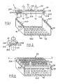
- FIG. 1 The components of the sample rack are shown in FIG. 1, a holder 20 for holding a plurality of sample vessels 30 and a stand 40 for the parallel exception of several such holders 20 (FIG. 3).
- a holder 20 consists of a plastic part 21 with side faces 24A, 24B pulled down on both sides on its long sides and vertical projections 23A, 23B bent downwards on both sides on its end faces, so that the holder 20 has an approximately trough-shaped shape. At the corner areas, that is in the transition area between the side surfaces 24A, 24B and the vertical lugs 23A, 23B, vertical slots 25A, 25B are left free.
- a grip strip 28 is also attached to an end face.
- each vertical extension 23A, 23B has an inward thickening 26A, 26B in its lower middle region, a depression 27A, 27B is provided on both sides of this thickening (27B on the right side of the holder 20 in the figures not shown).
- the two vertical lugs 23A, 23B are of equal length; the thickenings 26A, 26B extending to the lower edge of the lugs are of different widths (lugs 26B narrower than lugs 26A).
- the stand 40 is U-shaped, with a base part 40C and two parallel side parts 40A, 40B, the upper region of which is specially adapted to accommodate the holders 20:
- rectangular cutouts 40D, 40E are provided at the upper end, in each case lugs 41 on either side thereof.
- the cutouts 40E in the side part 40B are less wide than the cutouts 40D in the left side part 40A.
- a horizontal handle 48 is attached to the right side part 40B.
- the shape of the cutouts 40D, 40E is matched to the rear thickenings 26A, 26B of the holder 20 such that when a holder 20 is placed on the stand 40, the vertical projections 23A, 23B overlap the side parts 40A, 40B on the outside, the thickenings 26A, 26B are then inserted in a drawer-like manner and essentially in a form-fitting manner into an opposing pair of cutouts 40D, 40E and plunge into the remaining, uncut upper ends of the side parts in the slots 25A, 25B, the latter being particularly clear from FIG. 3.
- the lugs 41 also snap into the associated depressions 27A, B (snap connection between the holder 20 and the stand 40).
- the above-described different configuration of the thickenings and associated cutouts on the two sides of the carrier and the holder serve to cancel the symmetry of the holder 20 with respect to a central plane parallel to the side parts 40A, 40B of the stand 40, so that the holder 20 only in one defined position absolutely horizontal, ie can be placed parallel to the floor 40C on the stand 40, whereas if the holder 20 is mixed up (i.e. rotated by 180 °), the holder 20 is inclined slightly noticeably on the stand 40, since the (wider) inside thickening 26A on the left side of a holder 20 cannot be inserted into a (narrower) cutout 40E in the right side part 40B of the stand 40.
- the two grip strips 28, 48 are provided on the same side, in the exemplary embodiment on the right side, so that the correct assignment of the holder 20 in the stand 40 can be recognized immediately even without great user attention is.
- a marking strip for example a bar code, is applied to the side surface 24A of the holder 20.
- the openings 22 on the top of the holder 20 are provided with elastic plastic tongues 22A pointing downwards, which in the unloaded state (ie without the inserted sample vessel 30) point inwards, ie lie on a truncated cone jacket. whose axis is perpendicular to the top of the plastic part 21.
- these elastic plastic tongues 22A are more or less spread outwards, so that a frictional connection between these tongues 22A on the one hand and the sample vessel 30 on the other hand is strong enough that the holder 20 with the inserted sample vessels 30 can be transported without changing their vertical position in the holder 20.
- these plastic tongues 22A also have a centering effect on the sample vessels 30 insofar as they ensure a precise vertical alignment of the sample vessels.
- the bottom 40C has a number of depressions or bores 49 such that when the stand 40 is completely covered with holders 20 (FIG. 3), a bore 49 comes to lie vertically below each opening 22.
- the diameter of the bores 49 and their inner wall design is selected so that the sample vessels are laterally fixed; This can be achieved, for example, by a cross section of the bores 49 tapering downward, as a result of which sample vessels of different diameters can also be accommodated.
- FIG. 4 schematically shows a process sequence using the sample racks (holder 20, stand 40) according to the invention described in detail above, as is typical, for example, for carrying out an immunoassay:
- a test tube 60 contains, for example, the blood sample taken from a patient in which the substance of interest is to be detected (A).
- the serum used for the measurement which contains the analyte, is separated from the blood cells (B) and the serum is removed (C).
- the serum sample is usually stored temporarily as a primary sample (61) for distribution over several sample vessels for different tests.
- the relevant data such as the name of the patient, type of examination, etc., are recorded on a data carrier (Documentation D).
- sample vessels 30 are used, which are provided with a short identification in accordance with the documentation (F).
- the sample vessels 30 used here can already be provided with an antibody inner coating which is specific for the analyte to be detected.
- sample vessels are then inserted one after the other into the holders 20 placed on a stand 40 and pushed through to the bottom of the stand 40 (G), where their bottom dips into the holes 49 in the bottom 40.
- sample tubes can be placed in the holder at the manufacturer of the diagnostics. In this case, the tubes can be labeled very easily without having to remove them from the holder and readjust them after labeling.
- the serum taken from the primary sample and containing the analyte is poured into one of the sample vessels (H), then the next patient sample etc., until, for example, all sample tubes contain the patient sample.
- the reagents that is to say the labeled antibodies or antigens in the case of the immunoassay, are then pipetted in (I). This can either be done while the samples are in the rack or you take one holder after the other to add the reagents and then put it back in the rack.
- the stand 40 which is appropriately covered with holders, is then inserted into an incubator, in which the desired antigen-antibody reaction takes place, if appropriate, at elevated temperature (K). For this purpose, it may be necessary to shake the stand with the holders to accelerate this process.
- the stands and the holders are then placed in a washing machine (L). If this is not available in the laboratory, the sample vessels can be filled with cleaning reagent and the entire sample rack (rack + glasses) decanted. This operation can also be required several times under certain circumstances.
- sample vessels thus prepared are then inserted holder by holder into a carrier element rotating in the ordinary measuring device 50 and then pass the measuring point, where the substances initiating chemiluminescence are added and the resulting light output is measured, the intensity of which is a measure of the amount of the substance to be detected in the analyte (M).
- the holders with the measured sample vessels are then removed from their associated carrier element and thrown away (N).
- the fixed holding of the sample vessels in the sample rack also enables safe joint handling, for example when shaking or decanting, without having to remove individual sample vessels or holders.
- sample tubes for example with a coating
- the sample tubes are already supplied by the diagnostics manufacturer in holders, since they can then remain in the holders from sample preparation through measurement to disposal.
- the concept of the modular rack can also be advantageously used when using magnetic particles. It only has to be provided that the sample vessels must be in the area of influence of magnetic fields to effect the separation and during the actual separation step, while on the other hand, e.g. B. during incubation phases, the magnetic field should not act.
- the stand can therefore be designed in a known manner or with an open bottom surface that it can be placed on a substructure that contains magnets that, after placing the modular rack, the magnetic field required for separation on the magnetic particles in the suspension exercise.
- the magnets generally permanent magnets, are arranged so that they either pull the magnetic particles to the bottom or, in the lower area, to the sides of the sample vessels.
- the combination of holder, stand and substructure is then tipped over as a unit for decanting.
- the combination of holder and stand can then be detached from the base and, for example, washing liquid added. Then the combination holder and stand can be placed on the substructure again, waiting for the magnetic particles to settle on the wall and then decanted again.
Abstract
Description
Die Erfindung betrifft ein Probenrack für Probengefäße wie z.B. Reagenzgläser mit M x N Öffnungen auf seiner Oberseite zur Aufnahme von M x N Probengefäßen.The invention relates to a sample rack for sample vessels such as e.g. Test tubes with M x N openings on the top for holding M x N sample tubes.
Im medizinischen Bereich kennt man eine Vielzahl von Nachweisverfahren zur Entdeckung bzw. Identifizierung von bestimmten Substanzen, beispielsweise sogenannte Immunoassays.A large number of detection methods for the discovery or identification of certain substances are known in the medical field, for example so-called immunoassays.
Allen diesen Nachweisverfahren ist gemeinsam, daß zu ihrer Durchführung eine mehr oder weniger große Anzahl von Verfahrensschritten erforderlich ist, um ausgehend von der Probe des Patienten, in der die betreffende Substanz nachgewiesen werden soll, schrittweise durch Zugabe von spezifischen Reagenzien, beispielsweise markierten Antikörpern oder Antigenen, Entfernung überschüssiger Substanzen usw. den Nachweis zu führen.All of these detection methods have in common that a more or less large number of process steps are required to carry them out, step by step, based on the patient's sample in which the substance in question is to be detected, by adding specific reagents, for example labeled antibodies or antigens , Removal of excess substances, etc.
Die Durchführung solcher Meßverfahren im labortechnischen Maßstab erfolgt in aller Regel nicht "individuell", d.h. durch sukzessive Verarbeitung eines einzelnen Probengefäßes, sondern es sind Durchsatzmengen von bis zu mehreren Hundert Probengefäßen üblich. Hier taucht folglich das Problem auf, daß also eine große Anzahl von Probengefäße, in der Regel Reagenzgläser, schnell und sicher, d.h. ohne Vertauschung der Reihenfolge, diese Verfahrensschritte durchlaufen, wobei eine mehrfache Umsetzung der Probengefäße zwischen den Verfahrensschritten zu den jeweiligen dafür vorgesehenen Apparaturen und Einrichtungen und gegebenenfalls in ein Meßgerät erforderlich sein kann.Such measurement methods are generally not carried out “individually” on a laboratory scale, that is to say by successively processing a single sample vessel, but throughput rates of up to several hundred sample vessels are customary. The problem thus arises here that a large number of sample vessels, as a rule test tubes, pass through these process steps quickly and safely, that is to say without interchanging the sequence, with multiple conversion of the sample vessels between the process steps to the respective apparatus and Facilities and may be required in a measuring device.
Es ist daher üblich, die zur Durchführung einer solchen aus mehreren Verfahrensschritten bestehenden Messung verwendeten Probenbehälter in einem Probenrack aufzubewahren. Ein solches Probenrack besteht im einfachsten Fall aus einem Kunststoffunterbau mit beispielsweise 5 x 10 Bohrungen auf seiner Oberseite, in die die Probengefäße eingesteckt werden.It is therefore customary to store the sample containers used to carry out such a measurement consisting of several method steps in a sample rack. In the simplest case, such a sample rack consists of a plastic substructure with, for example, 5 x 10 bores on its upper side, into which the sample vessels are inserted.
Zur Vermeidung von Probenverwechslungen wird im allgemeinen jedes Probenröhrchen einzeln beschriftet. Diese Beschriftung kann z.B. erfolgen, solange die Röhrchen noch nicht im Probenrack sind. Manchmal werden jedoch die Proben schon vom Hersteller in Probenracks geliefert, dann müssen sie einzeln aus dem Probenrack entnommen, beschriftet, und anschließend wieder in das Probenrack eingestellt werden. Die Entnahme und das Wiedereinstellen sind arbeitsintensiv.To avoid mix-ups, each sample tube is generally labeled individually. This label can e.g. as long as the tubes are not yet in the sample rack. However, sometimes the samples are already delivered by the manufacturer in sample racks, then they have to be individually removed from the sample rack, labeled, and then put back into the sample rack. Removal and reinsertion are labor intensive.
Ein weiteres Problem ist die Zugabe von Substanzen, also etwa das Zupipettieren von Patientenproben sowie - im Falle des Immunoassays - der sogenannten Labels, nämlich der radioaktiv oder nicht-radioaktiv markierten Antigene oder Antikörper. Haben die Probenröhrchen z.B. die häufig verwendete Dimension von 12 mm Durchmesser und 75 mm Höhe, so ist es nicht möglich, mit gängigen Pipetten oder Dispensern mit der erforderlichen Genauigkeit in die senkrecht im Probenrack stehenden Proben hinein zu pipettieren. Dies gilt schon deshalb, weil man während des Pipettierens nicht den Boden der Probenröhrchen sehen kann so lange durch andere im Probenständer stehende Probengefäße der Blick gehindert wird. Deshalb ist es üblich, die Probenröhrchen zum Pipettieren einzeln zu entnehmen, mit der einen Hand schräg zu halten, und mit der anderen Hand die Pipette oder den Dispenser zu führen und zuzupipettieren. Danach wird jedes Probenröhrchen wieder einzeln in das Probenrack gestellt.Another problem is the addition of substances, for example the pipetting of patient samples and - in the case of immunoassays - the so-called labels, namely the radioactive or non-radioactive labeled antigens or antibodies. If the sample tubes e.g. the frequently used dimension of 12 mm in diameter and 75 mm in height, it is not possible to pipette into the samples standing vertically in the sample rack with the required accuracy using standard pipettes or dispensers. This is true because you cannot see the bottom of the sample tube while pipetting, as long as other sample vessels in the sample holder obstruct the view. It is therefore customary to take the sample tubes for pipetting individually, to hold them at an angle with one hand, and to guide and pipette in the pipette or the dispenser with the other hand. Then each sample tube is placed individually in the sample rack.
Ausgabe der Erfindung ist es daher, ein Probenrack so weiterzubilden, daß es bei höchstmöglicher Sicherheit in der Handhabung eine Vereinfachung des gesamten Verfahrensablaufs ermöglicht. Erfindungsgemäß wird diese Aufgabe durch den kennzeichnenden Teil des Patentanspruchs 1 gelöst.The issue of the invention is therefore to develop a sample rack in such a way that it simplifies the entire process sequence with the greatest possible safety in handling. According to the invention, this object is achieved by the characterizing part of
Der Grundgedanke der Erfindung besteht also in der modularen Gestaltung des Probenracks durch zweckmäßige Kombination zweier Bauteile insofern, als der Ständer eine sichere Aufnahme mehrerer Halterungen ermöglicht, wogegen der Halter, in dem die Probengefäße während sämtlicher Arbeitsgänge verbleiben, als "verlorenes" billiges Kunststoffteil ausgebildet sein kann, dessen Zweck lediglich die lineare räumliche Zuordnung einer Anzahl von Probengefäßen ist, und das nach Beendigung der Messung gegebenenfalls zusammen mit den Probengefäßen weggeworfen werden kann, wobei wegen der Minimalausführung eines solchen Halters auch nur geringe Entsorgungsprobleme entstehen. In diesem Halter können die Probengefäße von Anfang an eingesetzt werden und auch dort verbleiben, so daß aufwendige Umsetzvorgänge, die Anlaß für Vertauschungen und Verwechslungen sein können, während den Nachweisschritten zuverlässig vermieden werden.The basic idea of the invention thus consists in the modular design of the sample rack by a suitable combination of two components, in that the stand enables several holders to be securely accommodated, whereas the holder, in which the sample vessels remain during all operations, can be designed as a "lost" cheap plastic part can, the purpose of which is merely the linear spatial assignment of a number of sample vessels, and which, if appropriate, can be thrown away together with the sample vessels after the end of the measurement, the minimal design of such a holder also resulting in only minor disposal problems. In this holder, the sample vessels can be used from the beginning and also remain there, so that complex conversion processes, which can give rise to confusions and mix-ups, are reliably avoided during the detection steps.
Die oben geschilderten Nachteile, also das unter Umständen mehrmalige Entnehmen und Wiedereinstellen der Probenröhrchen in gängige Probenracks, werden durch die Verwendung des Halters vermieden.The disadvantages described above, that is the repeated removal and reinsertion of the sample tubes into common sample racks, are avoided by using the holder.
Die Probengefäße können ohne weiteres beschriftet werden, während sie sich im Halter befinden, sie müssen also nicht dazu entnommen werden.The sample vessels can be labeled easily while they are in the holder, so they do not have to be removed.
Dasselbe gilt für das Pipettieren. Der Benutzer kann den Halter mit z.B. 10 Proben in der einen Hand z.B. mit einem Winkel von 45° gegen die Vertikale geneigt halten, mit der anderen Hand die Pipette einführen und Flüssigkeiten, Suspensionen usw. zugeben, wobei jeweils das gesamte Probengefäß, insbesondere aber der untere Teil ganz im Blickfeld verbleibt, da ja jeweils nur eine Reihe von Probengefäßen im Halter sich befindet.The same applies to pipetting. The user can hold the holder with, for example, 10 samples in one hand, for example at an angle of 45 ° to the vertical, insert the pipette with the other hand and add liquids, suspensions, etc., whereby the entire sample vessel, but especially the the lower part remains in the field of vision, since there is only one row of sample vessels in the holder.
Jeweils nach Zugabe der Reagenzien wird dann ein Halter nach dem anderen in den Ständer eingesetzt, bis sich daraus wieder ein vollständiges, aber modular aus mehreren Haltern und einem Ständer aufgebautes Probenrack ergibt. In dem so zusammengesetzten Probenrack werden die Proben z.B. in einen Inkubator/Schüttler und/oder in eine Waschstation gebracht.After each addition of the reagents, one holder after the other is then inserted into the stand until a complete but modular sample rack consisting of several holders and a stand results. In the sample rack assembled in this way, the samples are e.g. placed in an incubator / shaker and / or in a washing station.
Erst zur gegebenenfalls erforderlichen externen Messung werden die Halter wieder aus dem Ständer entnommen und in das Meßgerät eingesetzt.The holders are removed from the stand and inserted into the measuring device only for the external measurement that may be required.
Ein Ausführungsbeispiel des erfindungsgemäßen Probenracks und seiner Handhabung wird anhand von Zeichnungen näher erläutert, es zeigen:
- Figur 1: eine Explosionsdarstellung des Ständers des Probenracks mit zugeordnetem Halter,
- Figur 2: eine teilweise geschnittene Darstellung der Einzelheit X in
Figur 1, - Figur 3: der Ständer gemäß
Figur 1 mit mehreren aufgesetzten Haltern, - Figuren 4A-N eine schematische Darstellung des Verfahrensablaufs am Beispiel eines Immunoassays unter Verwendung des erfindungsgemäßen Probenracks.
- FIG. 1: an exploded view of the stand of the sample rack with an associated holder,
- FIG. 2: a partially sectioned illustration of the detail X in FIG. 1,
- FIG. 3: the stand according to FIG. 1 with several holders attached,
- FIGS. 4A-N show a schematic representation of the process sequence using the example of an immunoassay using the sample rack according to the invention.
In Figur 1 sind die Komponenten des Probenracks dargestellt, ein Halter 20 zur Aufnahme mehrerer Probengefäße 30 und ein Ständer 40 zur parallelen Ausnahme mehrerer solcher Halter 20 (Figur 3).The components of the sample rack are shown in FIG. 1, a
Ein Halter 20 besteht aus einem Kunststoffteil 21 mit beidseitig an seinen Längsseiten heruntergezogenen Seitenflächen 24A,24B und beidseitig an seinen Stirnseiten nach unten abgebogenen vertikalen Ansätzen 23A,23B, so daß der Halter 20 eine etwa wannenförmige Gestalt besitzt. An den Eckbereichen, also im Übergangsbereich zwischen den Seitenflächen 24A,24B und den vertikalen Ansätzen 23A,23B, sind vertikale Schlitze 25A,25B ausgespart. An einer Stirnseite ist ferner eine Griffleiste 28 angebracht.A
Die Gestaltung der vertikalen Ansätze 23A,23B im einzelnen ist insbesondere aus Figur 2 entnehmbar. Symmetisch zur Längsmittelachse Y-Y des Halters 20 weist jeder vertikale Ansatz 23A,23B in seinem unteren mittleren Bereich eine nach innen gerichtete Verdickung 26A,26B auf, beidseitig dieser Verdickung ist jeweils eine Vertiefung 27A,27B vorgesehen (27B auf der rechten Seite des Halters 20 in den Figuren nicht dargestellt).The design of the
Die beiden vertikalen Ansätze 23A,23B sind gleich lang ausgebildet; die sich bis zur unteren Kante der Ansätze erstrekkenden Verdickungen 26A,26B sind verschieden brei ausgebildet (die Ansätze 26B schmaler als die Ansätze 26A).The two
Der Ständer 40 ist U-förmig ausgebildet, mit einem Bodenteil 40C und zwei parallelen Seitenteilen 40A,40B, deren oberer Bereich zur Aufnahme der Halter 20 speziell an diese angepaßt ist:The
Zunächst sind am oberen Ende rechteckige Aussparungen 40D,40E vorgesehen, jeweils beidseitig davon Ansätze 41. Hierbei sind die Ausschnitte 40E im Seitenteil 40B weniger breit als die Ausschnitte 40D im linken Seitenteil 40A.First,
Am rechten Seitenteil 40B ist eine horizontale Griffleiste 48 angebracht.A
Die Form der Ausschnitte 40D,40E ist derart auf die rückseitigen Verdickungen 26A,26B des Halters 20 abgestimmt, daß beim Aufsetzen eines Halters 20 auf den Ständer 40 die vertikalen Ansätze 23A,23B die Seitenteile 40A,40B außen übergreifen, wobei die Verdickungen 26A,26B dann schubladenähnlich und im wesentlichen formschlüssig in ein gegenüberliegendes Paar von Ausschnitten 40D,40E eingeschoben werden und in die stehen-gebliebenen, nicht ausgeschnittenen oberen Enden der Seitenteile in die Schlitze 25A,25B eintauchen, letzteres ist insbesondere aus Figur 3 deutlich entnehmbar. Hierbei rasten dann auch die Ansätze 41 in die zugeordneten Vertiefungen 27A,B ein (Schnappverbindung zwischen Halter 20 und Ständer 40).The shape of the
Die oben erläuterte unterschiedliche Ausgestaltung der Verdickungen und zugehörigen Ausschnitte auf den beiden Seiten des Trägers und des Halters dienen dazu, die Symmetrie des Halters 20 gegenüber einer Mittelebene parallel zu den Seitenteilen 40A,40B des Ständers 40 aufzuheben, so daß der Halter 20 nur in einer definierten Position absolut horizontal, d.h. parallel zum Boden 40C auf den Ständer 40 aufgesetzt werden kann, wogegen bei einer Vertauschung (also bei einer Verdrehung des Halters um 180°) es zu einer leicht bemerkbaren Schräglage des Halters 20 auf dem Ständer 40 kommt, da die (breitere) innenseitige Verdickung 26A auf der linken Seite eines Halters 20 nicht in einen (engeren) Ausschnitt 40E im rechten Seitenteil 40B des Ständers 40 einschiebbar ist.The above-described different configuration of the thickenings and associated cutouts on the two sides of the carrier and the holder serve to cancel the symmetry of the
Um hier Irrtümer von vornherein zu vermeiden, sind die beiden Griffleisten 28,48 auf der gleichen Seite, im Ausführungsbeispiel auf der rechten Seite, vorgesehen, so daß die richtige Zuordnung der Halter 20 in den Ständer 40 auch ohne große Aufmerksamkeit seitens des Benutzers sofort erkennbar ist.In order to avoid errors from the outset, the two
Diese Vorkehrungen bieten also eine doppelte Sicherung gegen einen möglicherweise falschen Einsatz von Haltern 20 in den Ständer 40. Dies muß unbedingt vermieden werden, da hierdurch eine Vertauschung der Reihenfolge der Probengefäße 30 im Halter 20 entstehen könnte, was für das Meßergebnis und damit für die betroffenen Patienten schwerwiegende Folgen haben könnte.These precautions therefore offer a double safeguard against a possibly incorrect use of
Da in Abhängigkeit vom jeweils angewandten Nachweisverfahren und der beim Benutzer vorhandenen Ausstattung für die einzelnen Arbeitsgänge eine mehrfache Entnahme und ein mehrfaches Wieder-einsetzen der Halter 20 in den Ständer 40 erforderlich sein kann, ist dieses doppelte Sicherheitssystem von besonderer Bedeutung.Since, depending on the detection method used and the equipment available to the user, it may be necessary to remove and reinsert the
Zur zusätzlichen Sicherung und zur Identifizierung der Proben ist an der Seitenfläche 24A des Halters 20 ein Markierungsstreifen, beispielsweise ein Bar-Code aufgebracht.For additional security and for identification of the samples, a marking strip, for example a bar code, is applied to the
Zur Halterung der Probengefäße 30 im Halter 20 sind die Öffnungen 22 auf der Oberseite des Halters 20 mit nach unten zeigenden, elastischen Kunststoffzungen 22A versehen, die im unbelasteten Zustand (also ohne eingeschobenes Probengefäß 30) nach innen zeigen, d.h., auf einem Kegelstumpfmantel liegen, dessen Achse senkrecht zur Oberseite des Kunststoffteils 21 liegt. Je nach Außendurchmesser des eingeführten Probengefäßes 30 werden diese elastischen Kunststoffzungen 22A dabei mehr oder weniger nach außen weggespreizt, so daß ein Reibschluß zwischen diesen Zungen 22A einerseits und dem Probengefäß 30 andererseits entsteht, der stark genug ist, daß der Halter 20 mit den eingesetzten Probengefäßen 30 transportiert werden kann, ohne daß diese ihre vertikale Position im Halter 20 verändern. Darüberhinaus haben diese Kunststoffzungen 22A auch noch einen zentrierenden Effekt auf die Probengefäße 30 insofern, als sie eine genaue vertikale Ausrichtung der Probengefäße sicherstellen.To hold the
Zur Unterstützung dieses Zentriereffektes weist der Boden 40C eine Anzahl von Vertiefungen oder Bohrungen 49 auf, derart, daß bei vollständiger Belegung des Ständers 40 mit Haltern 20 (Figur 3) vertikal unterhalb jeder Öffnung 22 eine Bohrung 49 zu liegen kommt. Der Durchmesser der Bohrungen 49 und deren Innenwandgestaltung ist so gewählt, daß die Probengefäße eine seitliche Fixierung erfahren; dies kann beispielsweise durch einen sich nach unten verjüngenden Querschnitt der Bohrungen 49 erreicht werden, wodurch auch Probengefäße unterschiedlichen Durchmessers aufgenommen werden können.To support this centering effect, the
In Figur 4 ist schematisch ein Verfahrensablauf unter Verwendung der oben im einzelnen beschriebenen erfindungsgemäßen Probenracks (Halter 20, Ständer 40) dargestellt, wie er beispielsweise für für die Durchführung eines Immunoassays typisch ist:FIG. 4 schematically shows a process sequence using the sample racks (
In einem Reagenzglas 60 befindet sich beispielsweise die von einem Patienten entnommene Blutprobe, in der die interessierende Substanz nachgewiesen werden soll (A). In einer Zentrifugierstation wird das zur Messung benutzte Serum, das den Analyten enthält, von den Blutkörperchen getrennt (B) und das Serum wird entnommen (C).A test tube 60 contains, for example, the blood sample taken from a patient in which the substance of interest is to be detected (A). In a centrifugation station, the serum used for the measurement, which contains the analyte, is separated from the blood cells (B) and the serum is removed (C).
Die Serumprobe wird meist als Primärprobe (61) zur Verteilung auf mehrere Probengefäße für unterschiedliche Untersuchungen zwischengelagert.The serum sample is usually stored temporarily as a primary sample (61) for distribution over several sample vessels for different tests.
Auf einem Datenträger werden die relevaten Daten, wie zum Beispiel der Name des Patienten, Art der Untersuchung usw. festgehalten (Dokumentation D).The relevant data, such as the name of the patient, type of examination, etc., are recorded on a data carrier (Documentation D).
Zur Durchführung des Immunoassays werden handelsübliche Probengefäße 30 verwendet, die in Übereinstimmung mit der Dokumentation mit einer Kurzidentifizierung versehen werden (F). Die hierbei verwendeten Probengefäße 30 können bei bestimmten Immunoassays bereits mit einer Antikörper-Innenbeschichtung versehen sein, die spezifisch für den nachzuweisenden Analyten ist.To carry out the immunoassay, commercially
Die gegebenenfalls vorbereiteten und beschrifteten Probengefäße werden dann nacheinander in die auf einem Ständer 40 aufgesetzten Halter 20 eingeführt und bis zum Boden des Ständers 40 durchgeschoben (G), wo ihr Boden in die Bohrungen 49 des Bodens 40 eintaucht. Als Alternative können die Probenröhrchen bereits beim Hersteller der Diagnostika in die Halter eingestellt werden. In diesem Fall können die Röhrchen sehr leicht beschriftet werden, ohne daß sie dazu aus dem Halter entnommen und nach der Beschriftung wieder eingestellt werden müssen.The optionally prepared and labeled sample vessels are then inserted one after the other into the
Daraufhin wird das aus der Primärprobe entnommene, den Analyten enthaltende Serum in eines der Probengefäße eingefüllt (H), sodann die nächste Patientenprobe usw., bis zum Beispiel alle Probenröhrchen die Patientenprobe enthalten. Anschließend werden die Reagenzien, also im Falle des Immunoassay die markierten Antikörper oder Antigene, zupipettiert (I). Dies kann entweder erfolgen, während sich die Proben im Rack befinden oder man entnimmt jeweils einen Halter nach dem anderen zur Reagenzienzugabe und stellt ihn danach wieder in den Ständer.Then the serum taken from the primary sample and containing the analyte is poured into one of the sample vessels (H), then the next patient sample etc., until, for example, all sample tubes contain the patient sample. The reagents, that is to say the labeled antibodies or antigens in the case of the immunoassay, are then pipetted in (I). This can either be done while the samples are in the rack or you take one holder after the other to add the reagents and then put it back in the rack.
Anschließend wird der entsprechend mit Haltern belegte Ständer 40 in einen Inkubator eingesetzt, in dem gegebenenfalls unter erhöhter Temperatur die erwünschte Antigen-Antikörper-Reaktion erfolgt (K). Hierzu kann es erforderlich sein, daß zur Beschleunigung dieses Ablaufs die Ständer mit den Haltern geschüttelt werden müssen.The
Da zum ordnungsgemäßen Ablauf des Immunoassays bei den beteiligten Substanzen überschüssige Bestandteile entfernt werden müssen, werden die Ständer mit den Haltern danach in ein Waschgerät eingesetzt (L). Sofern ein solches im Labor nicht vorhanden ist, können die Probengefäße mit Reinigungsreagenz gefüllt und das gesamte Probenrack (Ständer + Gläser) dekantiert werden. Auch dieser Arbeitsgang kann unter Umständen mehrfach erforderlich sein.Since excess components of the substances involved have to be removed for the immunoassay to work properly, the stands and the holders are then placed in a washing machine (L). If this is not available in the laboratory, the sample vessels can be filled with cleaning reagent and the entire sample rack (rack + glasses) decanted. This operation can also be required several times under certain circumstances.
Die so vorbereiteten Probengefäße werden dann Halter für Halter jeweils in ein im eingentlichen Meßgerät 50 umlaufendes Trägerelement eingesetzt und passieren dann die Meßstelle, wo die die Chemilumineszenz initiierenden Substanzen zugegeben und die daraus resultierende Lichtausbeute gemessen wird, deren Intensität ein Maß für die Menge der nachzuweisenden Substanz im Analyten bildet (M).The sample vessels thus prepared are then inserted holder by holder into a carrier element rotating in the
Danach werden die Halter mit den ausgemessenen Probengefäßen wieder aus ihrem zugehörigen Trägerelement entnommen und weggeworfen (N).The holders with the measured sample vessels are then removed from their associated carrier element and thrown away (N).
In letzterem ist eine Besonderheit insofern zu sehen, als im Gegensatz zu vorbekannten Verfahren auch der Halter 20 zusammen mit den Probengefäßen weggeworfen werden kann, was eine beträchtliche Vereinfachung und Einsparung weiterer Verfahrensschritte darstellt.In the latter, a special feature can be seen in that, in contrast to previously known methods, the
Von Bedeutung ist weiterhin, daß durch die feste Halterung der Probengefäße im Probenrack auch eine sichere gemeinsame Handhabung ermöglicht wird, beispielsweise beim Schütteln oder Dekantieren, ohne einzelne Probengefäße oder Halter entnehmen zu müssen.It is also important that the fixed holding of the sample vessels in the sample rack also enables safe joint handling, for example when shaking or decanting, without having to remove individual sample vessels or holders.
Beonders vorteilhaft ist es, wenn die Probenröhrchen, zum Beispiel mit Beschichtung, bereits vom Diagnostikahersteller in Haltern beliefert werden, da sie dann durchgängig von der Probenvorbereitung über die Messung bis zur Entsorgung in den Haltern verbleiben können.It is particularly advantageous if the sample tubes, for example with a coating, are already supplied by the diagnostics manufacturer in holders, since they can then remain in the holders from sample preparation through measurement to disposal.
Bei Immunoassays ist es auch üblich, Antigene oder Antikörper an in Suspension befindliche magnetische (meist paramagnetische) Teilchen zu binden. Zur Trennung von gebundenen und freien Reagenzien werden die in Suspension befindlichen Teilchen von externen Magneten an die Innenseite der Probengefäße gezogen, und in diesem Zustand kann die Flüssigkeit mit den nichtgebundenen Reagenzien durch Aspirieren oder Dekantieren aus den Probenröhrchen entfernt werden, während die magnetischen Teilchen im Röhrchen verbleiben.In immunoassays, it is also common to bind antigens or antibodies to magnetic (usually paramagnetic) particles in suspension. In order to separate bound and free reagents, the particles in suspension are drawn to the inside of the sample vessels by external magnets, and in this state the liquid with the unbound reagents can be removed from the sample tube by aspiration or decantation while the magnetic particles are in the tube remain.
Das erfindungsgemäße Konzept des modularen Racks, bestehend aus Halter und Ständer, kann auch bei der Verwendung von magnetischen Teilchen vorteilhaft angewendet werden. Es muß nur vorgesehen werden, daß die Probengefäße zum Bewirken der Trennung sowie beim eigentlichen Trennschritt selbst im Einflußbereich magnetischer Felder stehen müssen, während andererseits, z. B. bei Inkubationsphasen, des magnetische Feld nicht einwirken soll. Der Ständer kann daher in bekannter Weise auch so ausgebildet werden bzw. mit einer offenen Bodenfläche, daß er auf einen Unterbau gestellt werden kann, welcher Magnete enthält, die nach Aufsetzen des modularen Racks das zur Trennung erforderliche magnetische Feld auf die in der Suspension befindlichen Magnetpartikel ausüben. Die Magnete, im allgemeinen Permanentmagnete, sind dabei so angeordnet, daß sie die magnetischen Teilchen entweder an den Boden oder, im unteren Bereich, an die Seiten der Probengefäße ziehen.The concept of the modular rack, consisting of holder and stand, can also be advantageously used when using magnetic particles. It only has to be provided that the sample vessels must be in the area of influence of magnetic fields to effect the separation and during the actual separation step, while on the other hand, e.g. B. during incubation phases, the magnetic field should not act. The stand can therefore be designed in a known manner or with an open bottom surface that it can be placed on a substructure that contains magnets that, after placing the modular rack, the magnetic field required for separation on the magnetic particles in the suspension exercise. The magnets, generally permanent magnets, are arranged so that they either pull the magnetic particles to the bottom or, in the lower area, to the sides of the sample vessels.
Zum Dekantieren wird dann die Kombination aus Halter, Ständer und Unterbau als Einheit umgekippt.The combination of holder, stand and substructure is then tipped over as a unit for decanting.
Danach kann die Kombination aus Halter und Ständer wieder vom Unterbau gelöst und beispielsweise Waschflüssigkeit zugegeben werden. Danach kann die Kombination Halter und Ständer erneut auf den Unterbau aufgesetzt, das Absetzen der magnetischen Teilchen an der Wand abgewartet und sodann erneut dekantiert werden.The combination of holder and stand can then be detached from the base and, for example, washing liquid added. Then the combination holder and stand can be placed on the substructure again, waiting for the magnetic particles to settle on the wall and then decanted again.
Claims (16)
Priority Applications (1)
| Application Number | Priority Date | Filing Date | Title |
|---|---|---|---|
| AT89117451T ATE93412T1 (en) | 1988-10-24 | 1989-09-21 | SAMPLE HOLDER FOR SAMPLE VESSELS. |
Applications Claiming Priority (2)
| Application Number | Priority Date | Filing Date | Title |
|---|---|---|---|
| DE8813340U DE8813340U1 (en) | 1988-10-24 | 1988-10-24 | |
| DE8813340U | 1988-10-24 |
Publications (3)
| Publication Number | Publication Date |
|---|---|
| EP0365828A2 true EP0365828A2 (en) | 1990-05-02 |
| EP0365828A3 EP0365828A3 (en) | 1991-01-30 |
| EP0365828B1 EP0365828B1 (en) | 1993-08-25 |
Family
ID=6829192
Family Applications (1)
| Application Number | Title | Priority Date | Filing Date |
|---|---|---|---|
| EP89117451A Expired - Lifetime EP0365828B1 (en) | 1988-10-24 | 1989-09-21 | Rack for sample containers |
Country Status (4)
| Country | Link |
|---|---|
| US (1) | US5098663A (en) |
| EP (1) | EP0365828B1 (en) |
| AT (1) | ATE93412T1 (en) |
| DE (2) | DE8813340U1 (en) |
Cited By (30)
| Publication number | Priority date | Publication date | Assignee | Title |
|---|---|---|---|---|
| US5074505A (en) * | 1990-06-01 | 1991-12-24 | Akzo N.V. | Support attachment for holding bottles within a bottle block |
| CN103695291A (en) * | 2007-07-13 | 2014-04-02 | 汉迪实验室公司 | Integrated apparatus for performing nucleic acid extraction and diagnostic testing on multiple biological samples |
| US9028773B2 (en) | 2001-09-12 | 2015-05-12 | Handylab, Inc. | Microfluidic devices having a reduced number of input and output connections |
| US9051604B2 (en) | 2001-02-14 | 2015-06-09 | Handylab, Inc. | Heat-reduction methods and systems related to microfluidic devices |
| USD742027S1 (en) | 2011-09-30 | 2015-10-27 | Becton, Dickinson And Company | Single piece reagent holder |
| US9186677B2 (en) | 2007-07-13 | 2015-11-17 | Handylab, Inc. | Integrated apparatus for performing nucleic acid extraction and diagnostic testing on multiple biological samples |
| US9217143B2 (en) | 2007-07-13 | 2015-12-22 | Handylab, Inc. | Polynucleotide capture materials, and methods of using same |
| US9222954B2 (en) | 2011-09-30 | 2015-12-29 | Becton, Dickinson And Company | Unitized reagent strip |
| US9238223B2 (en) | 2007-07-13 | 2016-01-19 | Handylab, Inc. | Microfluidic cartridge |
| US9259735B2 (en) | 2001-03-28 | 2016-02-16 | Handylab, Inc. | Methods and systems for control of microfluidic devices |
| US9259734B2 (en) | 2007-07-13 | 2016-02-16 | Handylab, Inc. | Integrated apparatus for performing nucleic acid extraction and diagnostic testing on multiple biological samples |
| US9347586B2 (en) | 2007-07-13 | 2016-05-24 | Handylab, Inc. | Automated pipetting apparatus having a combined liquid pump and pipette head system |
| US9618139B2 (en) | 2007-07-13 | 2017-04-11 | Handylab, Inc. | Integrated heater and magnetic separator |
| USD787087S1 (en) | 2008-07-14 | 2017-05-16 | Handylab, Inc. | Housing |
| US9670528B2 (en) | 2003-07-31 | 2017-06-06 | Handylab, Inc. | Processing particle-containing samples |
| US9677121B2 (en) | 2001-03-28 | 2017-06-13 | Handylab, Inc. | Systems and methods for thermal actuation of microfluidic devices |
| US9765389B2 (en) | 2011-04-15 | 2017-09-19 | Becton, Dickinson And Company | Scanning real-time microfluidic thermocycler and methods for synchronized thermocycling and scanning optical detection |
| US9802199B2 (en) | 2006-03-24 | 2017-10-31 | Handylab, Inc. | Fluorescence detector for microfluidic diagnostic system |
| US9815057B2 (en) | 2006-11-14 | 2017-11-14 | Handylab, Inc. | Microfluidic cartridge and method of making same |
| USD814653S1 (en) | 2014-08-07 | 2018-04-03 | Becton, Dickinson And Company | Sample tube holder and components thereof |
| CN107971059A (en) * | 2018-01-12 | 2018-05-01 | 田艳 | A kind of portable blood examines rack for test tube |
| US10179910B2 (en) | 2007-07-13 | 2019-01-15 | Handylab, Inc. | Rack for sample tubes and reagent holders |
| US10364456B2 (en) | 2004-05-03 | 2019-07-30 | Handylab, Inc. | Method for processing polynucleotide-containing samples |
| US10571935B2 (en) | 2001-03-28 | 2020-02-25 | Handylab, Inc. | Methods and systems for control of general purpose microfluidic devices |
| US10799862B2 (en) | 2006-03-24 | 2020-10-13 | Handylab, Inc. | Integrated system for processing microfluidic samples, and method of using same |
| US10822644B2 (en) | 2012-02-03 | 2020-11-03 | Becton, Dickinson And Company | External files for distribution of molecular diagnostic tests and determination of compatibility between tests |
| US10900066B2 (en) | 2006-03-24 | 2021-01-26 | Handylab, Inc. | Microfluidic system for amplifying and detecting polynucleotides in parallel |
| US11453906B2 (en) | 2011-11-04 | 2022-09-27 | Handylab, Inc. | Multiplexed diagnostic detection apparatus and methods |
| US11806718B2 (en) | 2006-03-24 | 2023-11-07 | Handylab, Inc. | Fluorescence detector for microfluidic diagnostic system |
| US11959126B2 (en) | 2021-10-07 | 2024-04-16 | Handylab, Inc. | Microfluidic system for amplifying and detecting polynucleotides in parallel |
Families Citing this family (36)
| Publication number | Priority date | Publication date | Assignee | Title |
|---|---|---|---|---|
| US5575978A (en) | 1992-03-27 | 1996-11-19 | Abbott Laboratories | Sample container segment assembly |
| DE4212471A1 (en) * | 1992-04-14 | 1993-10-28 | Ostma Maschinenbau Gmbh | Carrier to be inserted into a packaging box for objects to be packed |
| US5324482A (en) * | 1992-08-27 | 1994-06-28 | David A. White | Pipette tip packaging system |
| US5571481A (en) * | 1995-02-17 | 1996-11-05 | Vicam, L.P. | Magnetic capture rack with slidable magnetic member |
| US5795784A (en) | 1996-09-19 | 1998-08-18 | Abbott Laboratories | Method of performing a process for determining an item of interest in a sample |
| US5856194A (en) | 1996-09-19 | 1999-01-05 | Abbott Laboratories | Method for determination of item of interest in a sample |
| DE904841T1 (en) * | 1997-09-29 | 2001-10-25 | Hoffmann La Roche | System for handling connections, consisting of vessels and supports |
| US7060226B1 (en) | 1997-11-24 | 2006-06-13 | Medax International, Inc. | Pipette tip packaging and transfer system |
| US6193892B1 (en) | 1999-03-03 | 2001-02-27 | Promega Corporation | Magnetic separation assembly and method |
| CN1113686C (en) * | 2001-06-04 | 2003-07-09 | 易荣大 | 3D motion type cyclone mixer |
| AU2002319595B2 (en) * | 2001-07-20 | 2007-06-07 | Gen-Probe Incorporated | Sample carrier and drip shield for use therewith |
| US20030087447A1 (en) * | 2001-11-08 | 2003-05-08 | Blouin Matthew R | Sample well strip |
| WO2003097239A1 (en) * | 2002-05-17 | 2003-11-27 | Gen-Probe Incorporated | Sample carrier having releasable locking mechanism |
| ATE337097T1 (en) | 2002-05-17 | 2006-09-15 | Gen Probe Inc | SAMPLE CARRIER WITH LOCKING DEVICE AND ASSOCIATED DRIP SCREEN DEVICE |
| WO2004105951A1 (en) * | 2003-05-28 | 2004-12-09 | Hte Aktiengesellschaft The High Throughput Experimentation Company | Modular sample holder system |
| ES2293127T3 (en) * | 2004-07-06 | 2008-03-16 | F. Hoffmann-La Roche Ag | ADAPTER SUPPORT SYSTEM. |
| US7910067B2 (en) | 2005-04-19 | 2011-03-22 | Gen-Probe Incorporated | Sample tube holder |
| ES2340289T3 (en) * | 2005-09-21 | 2010-06-01 | F. Hoffmann-La Roche Ltd. | SUPPORT FOR BUCKETS, DISPOSAL OF BUCKETS AND ANALYZER THAT UNDERSTANDS THESE ELEMENTS. |
| EP1850136A1 (en) * | 2006-04-28 | 2007-10-31 | F.Hoffmann-La Roche Ag | Shaker device for analyzer apparatus and analyzer comprising such a device |
| US7731899B2 (en) | 2007-02-08 | 2010-06-08 | Biokit, S.A. | Apparatus and methods for dispensing sample holders |
| EP2532425B1 (en) | 2007-10-23 | 2020-11-25 | Becton, Dickinson and Company | Multi-chambered tissue containment system for molecular and histology diagnostics |
| EP3284537B1 (en) | 2007-10-23 | 2019-08-28 | Becton, Dickinson and Company | Closed kit for tissue containment and stabilization for molecular and histopathology diagnostics |
| CN105618264B (en) * | 2009-05-15 | 2021-04-06 | 简·探针公司 | Method and apparatus for implementing automatic movement of a magnet in an instrument performing a magnetic separation procedure |
| US9144801B2 (en) | 2010-08-31 | 2015-09-29 | Abbott Laboratories | Sample tube racks having retention bars |
| EP2732878B1 (en) * | 2012-11-20 | 2018-09-12 | QIAGEN GmbH | Magnetic rack system and method for using a magnetic rack system |
| US10634584B2 (en) * | 2015-12-17 | 2020-04-28 | Roku, Inc. | Device for microscopic sample collection |
| US10392183B2 (en) * | 2016-06-06 | 2019-08-27 | Christopher Joseph-Paul Link | Funnel storage systems |
| TWI626992B (en) * | 2017-08-08 | 2018-06-21 | 元昌生技醫療私人股份有限公司 | Screening apparatus for tube collimation |
| IT201700116211A1 (en) | 2017-10-16 | 2019-04-16 | Inpeco Holding Ltd | TRACEABILITY SYSTEM FOR TRANSPORTATION OF CONTAINERS OF BIOLOGICAL SAMPLES |
| WO2019085890A1 (en) * | 2017-10-30 | 2019-05-09 | 南京金斯瑞生物科技有限公司 | Inclined magnetic holder |
| US10932647B1 (en) | 2018-04-25 | 2021-03-02 | 4 R Oceans, LLC | Drinking straw cleaning caddy |
| US10694922B1 (en) * | 2018-04-25 | 2020-06-30 | 4 R Oceans, LLC | Drinking straw cleaning caddy |
| USD981005S1 (en) * | 2020-04-14 | 2023-03-14 | Aesculap Ag | Sterile container labelling plate |
| CN111774123B (en) * | 2020-07-31 | 2021-08-31 | 中国人民解放军陆军军医大学第一附属医院 | Specimen holder |
| WO2022231665A1 (en) * | 2021-04-27 | 2022-11-03 | Micro Lab Solutions, Llc | Blood collection assembly and method of using the same |
| CN113198560B (en) * | 2021-05-06 | 2022-06-17 | 佳木斯大学 | Blood specimen test tube rack and identification alarm method |
Citations (4)
| Publication number | Priority date | Publication date | Assignee | Title |
|---|---|---|---|---|
| US3713771A (en) * | 1971-05-13 | 1973-01-30 | B Taylor | Method for organized assay and bendable test tube rack therefor |
| US4055396A (en) * | 1975-07-11 | 1977-10-25 | G. D. Searle & Co. | Tray and carrier assembly |
| DE2730214A1 (en) * | 1977-07-04 | 1979-01-11 | Franz Liebl | Sample carrier for analytical equipment - having holder block with transparent cover and indicating sheet reducing the need for writing and recording |
| EP0219802A2 (en) * | 1985-10-14 | 1987-04-29 | ALFI S.r.l. | Structure of a stand for supporting and containing test tubes and the like |
Family Cites Families (8)
| Publication number | Priority date | Publication date | Assignee | Title |
|---|---|---|---|---|
| NL7213664A (en) * | 1971-10-14 | 1973-04-17 | ||
| US3785773A (en) * | 1972-03-02 | 1974-01-15 | Beckman Instruments Inc | Chemical analysis tube module |
| GB1486210A (en) * | 1973-11-14 | 1977-09-21 | Suovaniemi Osmo Antero | Cuvette assembly for use in automatic reading and recording of reaction results |
| FR2277013A1 (en) * | 1974-07-05 | 1976-01-30 | Intertechnique Sa | IMPROVEMENTS TO SAMPLE CONVEYORS FOR MEASURING EQUIPMENT |
| SE8004687L (en) * | 1980-06-25 | 1981-12-26 | Clinicon Ab | AUTOMATIC ANALYSIS |
| US4495150A (en) * | 1983-07-25 | 1985-01-22 | Beckman Instruments, Inc. | Multiple object capturing and processing device |
| DE3405292A1 (en) * | 1984-02-15 | 1985-09-05 | Eppendorf Gerätebau Netheler + Hinz GmbH, 2000 Hamburg | METHOD FOR CARRYING OUT SAMPLES AND RACK FOR CARRYING OUT THE METHOD |
| US4895650A (en) * | 1988-02-25 | 1990-01-23 | Gen-Probe Incorporated | Magnetic separation rack for diagnostic assays |
-
1988
- 1988-10-24 DE DE8813340U patent/DE8813340U1/de not_active Expired
-
1989
- 1989-09-21 AT AT89117451T patent/ATE93412T1/en not_active IP Right Cessation
- 1989-09-21 EP EP89117451A patent/EP0365828B1/en not_active Expired - Lifetime
- 1989-09-21 DE DE89117451T patent/DE58905378D1/en not_active Expired - Fee Related
- 1989-10-24 US US07/426,300 patent/US5098663A/en not_active Expired - Fee Related
Patent Citations (4)
| Publication number | Priority date | Publication date | Assignee | Title |
|---|---|---|---|---|
| US3713771A (en) * | 1971-05-13 | 1973-01-30 | B Taylor | Method for organized assay and bendable test tube rack therefor |
| US4055396A (en) * | 1975-07-11 | 1977-10-25 | G. D. Searle & Co. | Tray and carrier assembly |
| DE2730214A1 (en) * | 1977-07-04 | 1979-01-11 | Franz Liebl | Sample carrier for analytical equipment - having holder block with transparent cover and indicating sheet reducing the need for writing and recording |
| EP0219802A2 (en) * | 1985-10-14 | 1987-04-29 | ALFI S.r.l. | Structure of a stand for supporting and containing test tubes and the like |
Cited By (76)
| Publication number | Priority date | Publication date | Assignee | Title |
|---|---|---|---|---|
| US5074505A (en) * | 1990-06-01 | 1991-12-24 | Akzo N.V. | Support attachment for holding bottles within a bottle block |
| US9051604B2 (en) | 2001-02-14 | 2015-06-09 | Handylab, Inc. | Heat-reduction methods and systems related to microfluidic devices |
| US9528142B2 (en) | 2001-02-14 | 2016-12-27 | Handylab, Inc. | Heat-reduction methods and systems related to microfluidic devices |
| US10571935B2 (en) | 2001-03-28 | 2020-02-25 | Handylab, Inc. | Methods and systems for control of general purpose microfluidic devices |
| US10619191B2 (en) | 2001-03-28 | 2020-04-14 | Handylab, Inc. | Systems and methods for thermal actuation of microfluidic devices |
| US9677121B2 (en) | 2001-03-28 | 2017-06-13 | Handylab, Inc. | Systems and methods for thermal actuation of microfluidic devices |
| US9259735B2 (en) | 2001-03-28 | 2016-02-16 | Handylab, Inc. | Methods and systems for control of microfluidic devices |
| US10351901B2 (en) | 2001-03-28 | 2019-07-16 | Handylab, Inc. | Systems and methods for thermal actuation of microfluidic devices |
| US9028773B2 (en) | 2001-09-12 | 2015-05-12 | Handylab, Inc. | Microfluidic devices having a reduced number of input and output connections |
| US11078523B2 (en) | 2003-07-31 | 2021-08-03 | Handylab, Inc. | Processing particle-containing samples |
| US10865437B2 (en) | 2003-07-31 | 2020-12-15 | Handylab, Inc. | Processing particle-containing samples |
| US10731201B2 (en) | 2003-07-31 | 2020-08-04 | Handylab, Inc. | Processing particle-containing samples |
| US9670528B2 (en) | 2003-07-31 | 2017-06-06 | Handylab, Inc. | Processing particle-containing samples |
| US10604788B2 (en) | 2004-05-03 | 2020-03-31 | Handylab, Inc. | System for processing polynucleotide-containing samples |
| US10364456B2 (en) | 2004-05-03 | 2019-07-30 | Handylab, Inc. | Method for processing polynucleotide-containing samples |
| US10443088B1 (en) | 2004-05-03 | 2019-10-15 | Handylab, Inc. | Method for processing polynucleotide-containing samples |
| US10494663B1 (en) | 2004-05-03 | 2019-12-03 | Handylab, Inc. | Method for processing polynucleotide-containing samples |
| US11441171B2 (en) | 2004-05-03 | 2022-09-13 | Handylab, Inc. | Method for processing polynucleotide-containing samples |
| US9802199B2 (en) | 2006-03-24 | 2017-10-31 | Handylab, Inc. | Fluorescence detector for microfluidic diagnostic system |
| US10913061B2 (en) | 2006-03-24 | 2021-02-09 | Handylab, Inc. | Integrated system for processing microfluidic samples, and method of using the same |
| US11806718B2 (en) | 2006-03-24 | 2023-11-07 | Handylab, Inc. | Fluorescence detector for microfluidic diagnostic system |
| US10799862B2 (en) | 2006-03-24 | 2020-10-13 | Handylab, Inc. | Integrated system for processing microfluidic samples, and method of using same |
| US11666903B2 (en) | 2006-03-24 | 2023-06-06 | Handylab, Inc. | Integrated system for processing microfluidic samples, and method of using same |
| US11141734B2 (en) | 2006-03-24 | 2021-10-12 | Handylab, Inc. | Fluorescence detector for microfluidic diagnostic system |
| US11142785B2 (en) | 2006-03-24 | 2021-10-12 | Handylab, Inc. | Microfluidic system for amplifying and detecting polynucleotides in parallel |
| US11085069B2 (en) | 2006-03-24 | 2021-08-10 | Handylab, Inc. | Microfluidic system for amplifying and detecting polynucleotides in parallel |
| US9080207B2 (en) | 2006-03-24 | 2015-07-14 | Handylab, Inc. | Microfluidic system for amplifying and detecting polynucleotides in parallel |
| US10695764B2 (en) | 2006-03-24 | 2020-06-30 | Handylab, Inc. | Fluorescence detector for microfluidic diagnostic system |
| US10900066B2 (en) | 2006-03-24 | 2021-01-26 | Handylab, Inc. | Microfluidic system for amplifying and detecting polynucleotides in parallel |
| US10857535B2 (en) | 2006-03-24 | 2020-12-08 | Handylab, Inc. | Integrated system for processing microfluidic samples, and method of using same |
| US10843188B2 (en) | 2006-03-24 | 2020-11-24 | Handylab, Inc. | Integrated system for processing microfluidic samples, and method of using the same |
| US10821436B2 (en) | 2006-03-24 | 2020-11-03 | Handylab, Inc. | Integrated system for processing microfluidic samples, and method of using the same |
| US10821446B1 (en) | 2006-03-24 | 2020-11-03 | Handylab, Inc. | Fluorescence detector for microfluidic diagnostic system |
| US9815057B2 (en) | 2006-11-14 | 2017-11-14 | Handylab, Inc. | Microfluidic cartridge and method of making same |
| US10710069B2 (en) | 2006-11-14 | 2020-07-14 | Handylab, Inc. | Microfluidic valve and method of making same |
| US9186677B2 (en) | 2007-07-13 | 2015-11-17 | Handylab, Inc. | Integrated apparatus for performing nucleic acid extraction and diagnostic testing on multiple biological samples |
| US9347586B2 (en) | 2007-07-13 | 2016-05-24 | Handylab, Inc. | Automated pipetting apparatus having a combined liquid pump and pipette head system |
| US10590410B2 (en) | 2007-07-13 | 2020-03-17 | Handylab, Inc. | Polynucleotide capture materials, and methods of using same |
| US11845081B2 (en) | 2007-07-13 | 2023-12-19 | Handylab, Inc. | Integrated apparatus for performing nucleic acid extraction and diagnostic testing on multiple biological samples |
| US9217143B2 (en) | 2007-07-13 | 2015-12-22 | Handylab, Inc. | Polynucleotide capture materials, and methods of using same |
| US10625261B2 (en) | 2007-07-13 | 2020-04-21 | Handylab, Inc. | Integrated apparatus for performing nucleic acid extraction and diagnostic testing on multiple biological samples |
| US10625262B2 (en) | 2007-07-13 | 2020-04-21 | Handylab, Inc. | Integrated apparatus for performing nucleic acid extraction and diagnostic testing on multiple biological samples |
| US10632466B1 (en) | 2007-07-13 | 2020-04-28 | Handylab, Inc. | Integrated apparatus for performing nucleic acid extraction and diagnostic testing on multiple biological samples |
| US9259734B2 (en) | 2007-07-13 | 2016-02-16 | Handylab, Inc. | Integrated apparatus for performing nucleic acid extraction and diagnostic testing on multiple biological samples |
| US11060082B2 (en) | 2007-07-13 | 2021-07-13 | Handy Lab, Inc. | Polynucleotide capture materials, and systems using same |
| US10717085B2 (en) | 2007-07-13 | 2020-07-21 | Handylab, Inc. | Integrated apparatus for performing nucleic acid extraction and diagnostic testing on multiple biological samples |
| US9238223B2 (en) | 2007-07-13 | 2016-01-19 | Handylab, Inc. | Microfluidic cartridge |
| US11549959B2 (en) | 2007-07-13 | 2023-01-10 | Handylab, Inc. | Automated pipetting apparatus having a combined liquid pump and pipette head system |
| US10071376B2 (en) | 2007-07-13 | 2018-09-11 | Handylab, Inc. | Integrated apparatus for performing nucleic acid extraction and diagnostic testing on multiple biological samples |
| US11466263B2 (en) | 2007-07-13 | 2022-10-11 | Handylab, Inc. | Diagnostic apparatus to extract nucleic acids including a magnetic assembly and a heater assembly |
| CN103695291A (en) * | 2007-07-13 | 2014-04-02 | 汉迪实验室公司 | Integrated apparatus for performing nucleic acid extraction and diagnostic testing on multiple biological samples |
| US9618139B2 (en) | 2007-07-13 | 2017-04-11 | Handylab, Inc. | Integrated heater and magnetic separator |
| US10844368B2 (en) | 2007-07-13 | 2020-11-24 | Handylab, Inc. | Diagnostic apparatus to extract nucleic acids including a magnetic assembly and a heater assembly |
| US10234474B2 (en) | 2007-07-13 | 2019-03-19 | Handylab, Inc. | Automated pipetting apparatus having a combined liquid pump and pipette head system |
| US10179910B2 (en) | 2007-07-13 | 2019-01-15 | Handylab, Inc. | Rack for sample tubes and reagent holders |
| US11266987B2 (en) | 2007-07-13 | 2022-03-08 | Handylab, Inc. | Microfluidic cartridge |
| US11254927B2 (en) | 2007-07-13 | 2022-02-22 | Handylab, Inc. | Polynucleotide capture materials, and systems using same |
| US10875022B2 (en) | 2007-07-13 | 2020-12-29 | Handylab, Inc. | Integrated apparatus for performing nucleic acid extraction and diagnostic testing on multiple biological samples |
| US10139012B2 (en) | 2007-07-13 | 2018-11-27 | Handylab, Inc. | Integrated heater and magnetic separator |
| US10065185B2 (en) | 2007-07-13 | 2018-09-04 | Handylab, Inc. | Microfluidic cartridge |
| USD787087S1 (en) | 2008-07-14 | 2017-05-16 | Handylab, Inc. | Housing |
| US9765389B2 (en) | 2011-04-15 | 2017-09-19 | Becton, Dickinson And Company | Scanning real-time microfluidic thermocycler and methods for synchronized thermocycling and scanning optical detection |
| US10781482B2 (en) | 2011-04-15 | 2020-09-22 | Becton, Dickinson And Company | Scanning real-time microfluidic thermocycler and methods for synchronized thermocycling and scanning optical detection |
| US11788127B2 (en) | 2011-04-15 | 2023-10-17 | Becton, Dickinson And Company | Scanning real-time microfluidic thermocycler and methods for synchronized thermocycling and scanning optical detection |
| USD831843S1 (en) | 2011-09-30 | 2018-10-23 | Becton, Dickinson And Company | Single piece reagent holder |
| US9222954B2 (en) | 2011-09-30 | 2015-12-29 | Becton, Dickinson And Company | Unitized reagent strip |
| USD742027S1 (en) | 2011-09-30 | 2015-10-27 | Becton, Dickinson And Company | Single piece reagent holder |
| USD905269S1 (en) | 2011-09-30 | 2020-12-15 | Becton, Dickinson And Company | Single piece reagent holder |
| US10076754B2 (en) | 2011-09-30 | 2018-09-18 | Becton, Dickinson And Company | Unitized reagent strip |
| US9480983B2 (en) | 2011-09-30 | 2016-11-01 | Becton, Dickinson And Company | Unitized reagent strip |
| US11453906B2 (en) | 2011-11-04 | 2022-09-27 | Handylab, Inc. | Multiplexed diagnostic detection apparatus and methods |
| US10822644B2 (en) | 2012-02-03 | 2020-11-03 | Becton, Dickinson And Company | External files for distribution of molecular diagnostic tests and determination of compatibility between tests |
| USD814653S1 (en) | 2014-08-07 | 2018-04-03 | Becton, Dickinson And Company | Sample tube holder and components thereof |
| CN107971059B (en) * | 2018-01-12 | 2019-11-12 | 田艳 | A kind of portable blood inspection rack for test tube |
| CN107971059A (en) * | 2018-01-12 | 2018-05-01 | 田艳 | A kind of portable blood examines rack for test tube |
| US11959126B2 (en) | 2021-10-07 | 2024-04-16 | Handylab, Inc. | Microfluidic system for amplifying and detecting polynucleotides in parallel |
Also Published As
| Publication number | Publication date |
|---|---|
| US5098663A (en) | 1992-03-24 |
| EP0365828B1 (en) | 1993-08-25 |
| EP0365828A3 (en) | 1991-01-30 |
| DE8813340U1 (en) | 1988-12-08 |
| ATE93412T1 (en) | 1993-09-15 |
| DE58905378D1 (en) | 1993-09-30 |
Similar Documents
| Publication | Publication Date | Title |
|---|---|---|
| EP0365828B1 (en) | Rack for sample containers | |
| EP0365827B1 (en) | Device for holding a plurality of sample containers for carrying out radiation measurements | |
| EP0849584B1 (en) | Apparatus (cuvette) for receiving and storing liquids and for performing optical measurements | |
| EP2927163B1 (en) | Vertical conveyor, sample distribution system and laboratory automation system | |
| DE19628178C1 (en) | Loading matrix-assisted laser desorption-ionisation sample plate for mass spectrometric analysis | |
| DE60213873T2 (en) | STACKABLE SAMPLE TRAY ASSEMBLY | |
| DE2349901C3 (en) | Device for row-wise transport of sample vessels arranged in a straight line one behind the other | |
| DE4313807C2 (en) | Reagent container system for the immunological analysis of a sample in an automatic analyzer | |
| DE102011108537B4 (en) | Positioning device for a laboratory device for distributing fluid samples and laboratory device with positioning device | |
| DE2103841A1 (en) | Blood testing device | |
| DE1805691B2 (en) | Method and device for analyzing liquid samples | |
| EP0644426A1 (en) | Analyser with a device for suspending particles, and suspension method therefor | |
| WO1985003886A1 (en) | Method and plant for simultaneously bringing a plurality of liquid samples on an object supporting plate | |
| DE3841961A1 (en) | Device for the analysis of physiological or other liquids in the recesses of a microtest plate | |
| DE69833846T2 (en) | Device for conveying components within an automatic analysis system | |
| EP4091715A1 (en) | Test strip assembly with containers | |
| DE4128698A1 (en) | Immunological analysis system for a specific combination reaction - contains extractors for specimen and reaction vessels on single rotor with washing and pipette stations on circumference | |
| DE19512430A1 (en) | Microtiter plate | |
| DE3313127A1 (en) | DEVICE FOR COLORING BIOLOGICAL SAMPLES | |
| DE4329791C2 (en) | Process for the automatic distribution and transport of microfilter disks | |
| EP1310303B1 (en) | Reservoir for various different reagents for carrying out an assay | |
| EP3666381A1 (en) | Laboratory device for automatic treatment of laboratory samples | |
| DE2921743A1 (en) | Cassette for holding large number of clinical samples - being capable of variety of pretreatment operations before radiation analysis | |
| EP3211423A1 (en) | Automatic analyzer with receiving positions for liquid container | |
| EP3608676B1 (en) | Insert sample into pipette tip box for further processing |
Legal Events
| Date | Code | Title | Description |
|---|---|---|---|
| PUAI | Public reference made under article 153(3) epc to a published international application that has entered the european phase |
Free format text: ORIGINAL CODE: 0009012 |
|
| AK | Designated contracting states |
Kind code of ref document: A2 Designated state(s): AT CH DE ES FR GB IT LI NL SE |
|
| PUAL | Search report despatched |
Free format text: ORIGINAL CODE: 0009013 |
|
| AK | Designated contracting states |
Kind code of ref document: A3 Designated state(s): AT CH DE ES FR GB IT LI NL SE |
|
| 17P | Request for examination filed |
Effective date: 19910702 |
|
| 17Q | First examination report despatched |
Effective date: 19920602 |
|
| RAP1 | Party data changed (applicant data changed or rights of an application transferred) |
Owner name: LABORATORIUM PROF. DR. RUDOLF BERTHOLD GMBH & CO. |
|
| GRAA | (expected) grant |
Free format text: ORIGINAL CODE: 0009210 |
|
| AK | Designated contracting states |
Kind code of ref document: B1 Designated state(s): AT CH DE ES FR GB IT LI NL SE |
|
| PG25 | Lapsed in a contracting state [announced via postgrant information from national office to epo] |
Ref country code: IT Free format text: LAPSE BECAUSE OF FAILURE TO SUBMIT A TRANSLATION OF THE DESCRIPTION OR TO PAY THE FEE WITHIN THE PRE;WARNING: LAPSES OF ITALIAN PATENTS WITH EFFECTIVE DATE BEFORE 2007 MAY HAVE OCCURRED AT ANY TIME BEFORE 2007. THE CORRECT EFFECTIVE DATE MAY BE DIFFERENT FROM THE ONE RECORDED.SCRIBED TIME-LIMIT Effective date: 19930825 Ref country code: NL Effective date: 19930825 Ref country code: SE Effective date: 19930825 Ref country code: ES Free format text: THE PATENT HAS BEEN ANNULLED BY A DECISION OF A NATIONAL AUTHORITY Effective date: 19930825 |
|
| REF | Corresponds to: |
Ref document number: 93412 Country of ref document: AT Date of ref document: 19930915 Kind code of ref document: T |
|
| PG25 | Lapsed in a contracting state [announced via postgrant information from national office to epo] |
Ref country code: AT Effective date: 19930921 |
|
| PG25 | Lapsed in a contracting state [announced via postgrant information from national office to epo] |
Ref country code: CH Effective date: 19930930 Ref country code: LI Effective date: 19930930 |
|
| REF | Corresponds to: |
Ref document number: 58905378 Country of ref document: DE Date of ref document: 19930930 |
|
| ET | Fr: translation filed | ||
| GBT | Gb: translation of ep patent filed (gb section 77(6)(a)/1977) |
Effective date: 19931123 |
|
| NLV1 | Nl: lapsed or annulled due to failure to fulfill the requirements of art. 29p and 29m of the patents act | ||
| REG | Reference to a national code |
Ref country code: CH Ref legal event code: PL |
|
| PLBE | No opposition filed within time limit |
Free format text: ORIGINAL CODE: 0009261 |
|
| STAA | Information on the status of an ep patent application or granted ep patent |
Free format text: STATUS: NO OPPOSITION FILED WITHIN TIME LIMIT |
|
| PGFP | Annual fee paid to national office [announced via postgrant information from national office to epo] |
Ref country code: DE Payment date: 19940714 Year of fee payment: 6 |
|
| 26N | No opposition filed | ||
| PGFP | Annual fee paid to national office [announced via postgrant information from national office to epo] |
Ref country code: GB Payment date: 19940905 Year of fee payment: 6 |
|
| PGFP | Annual fee paid to national office [announced via postgrant information from national office to epo] |
Ref country code: FR Payment date: 19940919 Year of fee payment: 6 |
|
| PG25 | Lapsed in a contracting state [announced via postgrant information from national office to epo] |
Ref country code: GB Effective date: 19950921 |
|
| GBPC | Gb: european patent ceased through non-payment of renewal fee |
Effective date: 19950921 |
|
| PG25 | Lapsed in a contracting state [announced via postgrant information from national office to epo] |
Ref country code: FR Effective date: 19960531 |
|
| PG25 | Lapsed in a contracting state [announced via postgrant information from national office to epo] |
Ref country code: DE Effective date: 19960601 |
|
| REG | Reference to a national code |
Ref country code: FR Ref legal event code: ST |