EP0364293A2 - Blood pumping catheter - Google Patents
Blood pumping catheter Download PDFInfo
- Publication number
- EP0364293A2 EP0364293A2 EP89310536A EP89310536A EP0364293A2 EP 0364293 A2 EP0364293 A2 EP 0364293A2 EP 89310536 A EP89310536 A EP 89310536A EP 89310536 A EP89310536 A EP 89310536A EP 0364293 A2 EP0364293 A2 EP 0364293A2
- Authority
- EP
- European Patent Office
- Prior art keywords
- end portion
- catheter
- aorta
- pump
- pump means
- Prior art date
- Legal status (The legal status is an assumption and is not a legal conclusion. Google has not performed a legal analysis and makes no representation as to the accuracy of the status listed.)
- Withdrawn
Links
Images

Classifications
-
- A—HUMAN NECESSITIES
- A61—MEDICAL OR VETERINARY SCIENCE; HYGIENE
- A61M—DEVICES FOR INTRODUCING MEDIA INTO, OR ONTO, THE BODY; DEVICES FOR TRANSDUCING BODY MEDIA OR FOR TAKING MEDIA FROM THE BODY; DEVICES FOR PRODUCING OR ENDING SLEEP OR STUPOR
- A61M60/00—Blood pumps; Devices for mechanical circulatory actuation; Balloon pumps for circulatory assistance
- A61M60/10—Location thereof with respect to the patient's body
- A61M60/122—Implantable pumps or pumping devices, i.e. the blood being pumped inside the patient's body
- A61M60/126—Implantable pumps or pumping devices, i.e. the blood being pumped inside the patient's body implantable via, into, inside, in line, branching on, or around a blood vessel
- A61M60/135—Implantable pumps or pumping devices, i.e. the blood being pumped inside the patient's body implantable via, into, inside, in line, branching on, or around a blood vessel inside a blood vessel, e.g. using grafting
- A61M60/139—Implantable pumps or pumping devices, i.e. the blood being pumped inside the patient's body implantable via, into, inside, in line, branching on, or around a blood vessel inside a blood vessel, e.g. using grafting inside the aorta, e.g. intra-aortic balloon pumps
-
- A—HUMAN NECESSITIES
- A61—MEDICAL OR VETERINARY SCIENCE; HYGIENE
- A61M—DEVICES FOR INTRODUCING MEDIA INTO, OR ONTO, THE BODY; DEVICES FOR TRANSDUCING BODY MEDIA OR FOR TAKING MEDIA FROM THE BODY; DEVICES FOR PRODUCING OR ENDING SLEEP OR STUPOR
- A61M60/00—Blood pumps; Devices for mechanical circulatory actuation; Balloon pumps for circulatory assistance
- A61M60/20—Type thereof
- A61M60/205—Non-positive displacement blood pumps
- A61M60/216—Non-positive displacement blood pumps including a rotating member acting on the blood, e.g. impeller
- A61M60/237—Non-positive displacement blood pumps including a rotating member acting on the blood, e.g. impeller the blood flow through the rotating member having mainly axial components, e.g. axial flow pumps
-
- A—HUMAN NECESSITIES
- A61—MEDICAL OR VETERINARY SCIENCE; HYGIENE
- A61M—DEVICES FOR INTRODUCING MEDIA INTO, OR ONTO, THE BODY; DEVICES FOR TRANSDUCING BODY MEDIA OR FOR TAKING MEDIA FROM THE BODY; DEVICES FOR PRODUCING OR ENDING SLEEP OR STUPOR
- A61M60/00—Blood pumps; Devices for mechanical circulatory actuation; Balloon pumps for circulatory assistance
- A61M60/40—Details relating to driving
- A61M60/403—Details relating to driving for non-positive displacement blood pumps
- A61M60/408—Details relating to driving for non-positive displacement blood pumps the force acting on the blood contacting member being mechanical, e.g. transmitted by a shaft or cable
- A61M60/411—Details relating to driving for non-positive displacement blood pumps the force acting on the blood contacting member being mechanical, e.g. transmitted by a shaft or cable generated by an electromotor
-
- A—HUMAN NECESSITIES
- A61—MEDICAL OR VETERINARY SCIENCE; HYGIENE
- A61M—DEVICES FOR INTRODUCING MEDIA INTO, OR ONTO, THE BODY; DEVICES FOR TRANSDUCING BODY MEDIA OR FOR TAKING MEDIA FROM THE BODY; DEVICES FOR PRODUCING OR ENDING SLEEP OR STUPOR
- A61M60/00—Blood pumps; Devices for mechanical circulatory actuation; Balloon pumps for circulatory assistance
- A61M60/80—Constructional details other than related to driving
- A61M60/855—Constructional details other than related to driving of implantable pumps or pumping devices
- A61M60/861—Connections or anchorings for connecting or anchoring pumps or pumping devices to parts of the patient's body
-
- A—HUMAN NECESSITIES
- A61—MEDICAL OR VETERINARY SCIENCE; HYGIENE
- A61M—DEVICES FOR INTRODUCING MEDIA INTO, OR ONTO, THE BODY; DEVICES FOR TRANSDUCING BODY MEDIA OR FOR TAKING MEDIA FROM THE BODY; DEVICES FOR PRODUCING OR ENDING SLEEP OR STUPOR
- A61M60/00—Blood pumps; Devices for mechanical circulatory actuation; Balloon pumps for circulatory assistance
- A61M60/10—Location thereof with respect to the patient's body
- A61M60/122—Implantable pumps or pumping devices, i.e. the blood being pumped inside the patient's body
- A61M60/126—Implantable pumps or pumping devices, i.e. the blood being pumped inside the patient's body implantable via, into, inside, in line, branching on, or around a blood vessel
- A61M60/148—Implantable pumps or pumping devices, i.e. the blood being pumped inside the patient's body implantable via, into, inside, in line, branching on, or around a blood vessel in line with a blood vessel using resection or like techniques, e.g. permanent endovascular heart assist devices
-
- A—HUMAN NECESSITIES
- A61—MEDICAL OR VETERINARY SCIENCE; HYGIENE
- A61M—DEVICES FOR INTRODUCING MEDIA INTO, OR ONTO, THE BODY; DEVICES FOR TRANSDUCING BODY MEDIA OR FOR TAKING MEDIA FROM THE BODY; DEVICES FOR PRODUCING OR ENDING SLEEP OR STUPOR
- A61M60/00—Blood pumps; Devices for mechanical circulatory actuation; Balloon pumps for circulatory assistance
- A61M60/40—Details relating to driving
- A61M60/403—Details relating to driving for non-positive displacement blood pumps
- A61M60/408—Details relating to driving for non-positive displacement blood pumps the force acting on the blood contacting member being mechanical, e.g. transmitted by a shaft or cable
- A61M60/411—Details relating to driving for non-positive displacement blood pumps the force acting on the blood contacting member being mechanical, e.g. transmitted by a shaft or cable generated by an electromotor
- A61M60/414—Details relating to driving for non-positive displacement blood pumps the force acting on the blood contacting member being mechanical, e.g. transmitted by a shaft or cable generated by an electromotor transmitted by a rotating cable, e.g. for blood pumps mounted on a catheter
-
- Y—GENERAL TAGGING OF NEW TECHNOLOGICAL DEVELOPMENTS; GENERAL TAGGING OF CROSS-SECTIONAL TECHNOLOGIES SPANNING OVER SEVERAL SECTIONS OF THE IPC; TECHNICAL SUBJECTS COVERED BY FORMER USPC CROSS-REFERENCE ART COLLECTIONS [XRACs] AND DIGESTS
- Y10—TECHNICAL SUBJECTS COVERED BY FORMER USPC
- Y10S—TECHNICAL SUBJECTS COVERED BY FORMER USPC CROSS-REFERENCE ART COLLECTIONS [XRACs] AND DIGESTS
- Y10S415/00—Rotary kinetic fluid motors or pumps
- Y10S415/90—Rotary blood pump
Definitions
- the invention relates to a catheter for pumping blood through the vascular system of a living being.
- US-A-4,753,221 the entire disclosure of which is to be incorporated whereby this reference discloses apparatus comprising an elongated catheter having a distal end portion which is of sufficiently small diameter and sufficient flexibility to enable it to be passed through a portion of the being's vascular system so that the distal end portion of the catheter is located within or closely adjacent the being's heart.
- the catheter includes an expandable pump member located at the distal end portion and drive means for effecting the operation of the pump.
- the distal end portion of the catheter includes an inlet for blood to flow therein and an outlet for blood to flow thereout.
- the instrument can be used for either left side heart applications or right side heart applications.
- the catheter When used for left side heart applications, the catheter is constructed so that the inlet is in fluid communication with the left ventricle while the outlet is in fluid communication with the aorta. When used for right side heart applications, the catheter is constructed so that the inlet is in fluid communication with the right ventricle while the outlet is in fluid communication with the pulmonary artery.
- the distal end portion of the instrument is arranged to extend through the aortic valve. In another embodiment the distal end portion is located over the aortic valve and includes a cover to contact valve while enabling blood to flow therethrough. In all cases the blood can be pumped through the heart and into the vascular system without requiring any pumping action of the heart itself.
- the placing of the known catheter through or immediately adjacent the aortic valve is a skilled job which is normally only done by highly trained medical personnel. It is one object of the invention to provide a blood pumping catheter which is safe and easy to use and which may be used by less skilled medical personnel.
- the invention provides in one aspect apparatus to be located within the aorta of a living being to pump blood through the vascular system of the being in the absence of contact with the aortic valve, the apparatus comprising an elongate catheter having an end portion to be located distally of the operator and dimensioned to be received within the aorta so that the end portion is in proximity to the aortic valve, comprising pump means located at the end portion and drive means operatively connected to the pump means, the end portion including an inlet located distally of the pump means and an outlet located proximately of the pump means, the inlet and outlet being in fluid communication with the aorta, barrier means being present to direct substantially all of the blood flowing through the aorta into the inlet, through the pump means and out through the outlet characterised in that the barrier means is located about the end portion and is adapted to contact the wall of the aorta in blood flow sealing engagement at a location longitudinally spaced from and upstream of the aortic valve.
- the distal end portion preferably comprises a flexible tubular portion extending about the pump means and the barrier means comprises a flexible skirt extending about the periphery of the tubular portion.
- the distal end portion and the pump means in the form of an impeller or the like, are preferably arranged to be expandable between a retracted configuration during insertion of the catheter, and an expanded configuration when the distal end portion is in the operative position spaced apart from the aortic valve.
- the invention provides a catheter to be located within the aorta of a person for pumping blood through the vascular system of the person, the catheter comprising rotary pump means disposed at the end of the catheter distal from the operator, rotary drive means operatively connected to the pump means extending within the catheter, a tube extending about the pump means and defining an inlet for the flow of blood to the pump means at one end and an outlet at the other characterised by a flexible skirt extending about the periphery of the tube, the skirt being hingedly connected to the tube and arranged in use to extend generally parallel to the axis of the tube to sealingly engage the side walls of the aorta to hold the end at a position longitudinally spaced from and upstream of the aortic valve.
- the invention provides a catheter to be placed within the body of a person characterised in that the catheter comprises an outer sleeve having a flexible tube-like end portion to be located distally of the operator, the end portion being expandable between a retracted condition during insertion of the catheter and an expanded condition when the end portion is at the desired location within the body, a plurality of fingers disposed about the periphery of the end portion and arranged to be movable to expand the end portion between the retracted and expanded conditions.
- apparatus (20) is arranged to be disposed within the vascular system, and in particular, the aorta (22, Figure 2) to effect the pumping of blood through the vascular system.
- the apparatus comprises a catheter having pumping means (24) located at its distal end portion (26), i.e that end remote from the operator.
- the catheter comprises an elongated outer tube or sleeve (20A) of small diameter, e.g 5 to 10 French (1.7-3.3 mm), with various components located therein and with the pumping means (24) and barrier means, to be described later, at its distal end portion (26).
- the catheter is sufficiently flexible to enable it to be passed through the vascular system to its desired position within the aorta remote (i.e downstream) from the aortic valve (28) ( Figure 2).
- the positioning of the catheter (20) is carried out through the use of a conventional tubular guide catheter (not shown), which is first introduced and threaded through the vascular system in a conventional manner.
- the catheter (20) is inserted percutaneously into the femoral artery (not shown), up through the descending aorta (not shown) until its distal end portion (26) is located at a desired position within the aorta (22) downstream of the aortic valve (28) and downstream of the junction of the coronary arteries (30) to the aorta.
- the distal end portion (26) may be located within the ascending aorta, the aortic arch or the descending aorta, as desired.
- the distal end portion (26) of the catheter (20) includes the pump means (24). That means can take various forms such as those disclosed in US-A-4,753,221.
- the pump means (24) is preferably a centrifugal pump which is arranged to be operated, e.g rotated, by drive means (32) shown.
- the drive means (32) can take various forms, but preferably comprises the high speed rotary drive system described and claimed in US-A-4,606,902 entitled Spiral Wire Bearing for Rotating Wire Drive Catheter, the disclosure of which is incorporated by reference herein.
- That drive system comprises an elongated drive wire or cable (32A) supported in the centre of the catheter tube (20A) along its central longitudinal axis (34), by means of a spiral bearing (32B).
- That bearing comprises a helical or spiral coil of wire extending substantially the entire length of the catheter tube from a proximately located point outside the body to the distal end portion of the catheter.
- the outer diameter of the helical bearing is sufficiently great so that its loops just clear the interior surface of the catheter tube (20A) to hold the bearing securely in place therein.
- the inside diameter of the central passage extending down the length of the helical bearing is just slightly greater than the outside diameter of the drive cable so the drive cable can rotate freely therein.
- the drive cable may be swaged or drawn to increase the engaging surface area thereof, while the cross-sectional shape of the spiral bearing can be rectangular to also increase the engaging surface area.
- the drive cable is arranged to be connected at the proximal end thereof to an electric motor (not shown) or some other drive means for rotating the cable at high speed, e.g from 10,000 to 200,000 rpm, to effect the operation of the pump (24).
- the distal end portion of the catheter is of a generally tubular construction which is arranged to be expanded from a retracted orientation (not shown) to an expanded orientation (as shown in Figures 1 to 3), and vice versa.
- a retracted orientation not shown
- an expanded orientation as shown in Figures 1 to 3
- the distal end portion is in the compact orientation its outside diameter is sufficiently small to enable the catheter to be readily inserted longitudinally into the aorta, via a percutaneous insertion at a desired location, e.g into the femoral artery.
- the pump (24) is an expandable/contractible member so that when the distal end portion of the catheter is expanded, automatically expands from a closed or compact position to the open, operative position.
- the pump (24) is an axial type pump basically comprising a central hub (24A) from which four blades or impellers (24B) extend.
- the blades are biased to naturally project outward radially.
- the blades are formed of flexible material so that when the distal end portion of the catheter (20) is compacted (unexpanded) the blades are flexed into the closed or compressed position extending beside one another. When released or freed they extend radially outward from the hub (24A).
- each of the blades (24B) is angled so that when the pump is rotated about the central axis (34) of the catheter the blades (24B) draw blood from the heart into an inlet (to be described later) in the distal end portion of the catheter to the blades and from there the blades force the blood out of an outlet into the direction of arrows (to be described later) into the aorta (22).
- the proximal end of the hub (24A) is connected to the distal end of the drive cable (32A) so that the rotation of cable causes the concomitant rotation of pump's blades (24B).
- each of the blades (24B) are preferably rounded so as not to present any sharp edges which could adversely affect the blood cells pumped thereby.
- the pump (24) is held in position centered within the distal end portion by a bearing support (36).
- the distal end portion of the catheter (20) is in the form of a cup-shaped member (38).
- the member (38) is formed of a flexible and/or resilient material, e.g an elastomeric material.
- the member (38) is tubular in shape, e.g it constitutes a truncated cone, including an enlarged diameter open ree end (40) located at the distal end thereof and a smaller diameter open end (42) located at the proximal end thereof.
- the cup-shaped member (38) is mounted on the sleeve (20A) forming the outer wall of the catheter at the distal end thereof via a plurality of resilient fingers (44). The fingers extend at equally spaced locations about the periphery of the catheter's sleeve (20A).
- Each finger (44) is formed of a resilient material and is slightly arcuate in shape.
- the distal end (46) of each of the fingers (44) is secured to the outer periphery of the cup-shaped member immediately adjacent the opening (42) while the proximal end (48) of each of the fingers (44) is fixed to the catheter sleeve (20A).
- Each of the fingers (44) is biased radially outward so that when unconstrained, they move to the expanded position shown in the drawings, thereby expanding the cup-shaped member (38) from a retracted or compacted orientation (not shown), in which it is somewhat like a folded umbrella, to the expanded orientation shown.
- the fingers (44) and the cup-shaped member (38) are arranged to be compressed or contracted radially inward by being disposed within the tubular guide and/or introducing catheter (not shown) during placement of the device (20) in the patient.
- the device is arranged to be inserted through a conventional tubular guide/introducing catheter into the body to the desired position within the aorta and the guide/introducing catheter is then retracted to expose the distal end portion of the device (20).
- This action enables the resilient fingers (44) to move radially outward to the position shown, thereby causing the cup-shaped member (38) to also assume the expanded orientation shown.
- the flared open end (40) of the cup-shaped member (38) serves as the inlet to the pump (24), while the smaller diameter opening (42) and the open spaces (50) between the fingers (44) contiguous with the opening (42) serves as the outlet from the pump.
- the pump is located so that its blades are disposed within the cup shaped member (38) between the inlet and the outlet.
- the distal end portion of the catheter includes the heretofore mentioned barrier means. That means is in the form of a barrier wall of a flexible skirt (62) which extends about the periphery of cupshaped member (38) contiguous with the opening (inlet) (40).
- the skirt is very flexible so that it engages and conforms to the periphery of the inner surface of the aorta as shown clearly in Figures 2 and 3.
- This action has the effect of isolating the portion of the aorta (22) upstream (distally) of the pump from the portion of the aorta downstream (proximally) of the pump, except for the passageway through the pump itself, i.e through the cup-shaped member (38) from the inlet to the outlet.
- the operation of the catheter's pump will be co-ordinated with the pumping action of the heart.
- the speed of the pump is cycled, i.e slowed down or stopped, in synchronism with the pumping action of the heart so that there will be repetitive periods when the higher pressure downstream of the pump pushes the blood upstream of the pump into the coronary arteries.
- the pump speed/time cycle can be established and/or adjusted to anything desired.
- barrier wall (52) provides the isolation function described above, it also serves to hold the distal end of the catheter at the desired operative position within the aorta.
- the catheter since the catheter is arranged to be located at a position remote from the heart and the aortic valve, it can be used by less skilled personnel than would otherwise be required if the catheter had to be located into the heart through the aortic valve or immediately over the aortic valve. Moreover, some medical situations, e.g a patient having a calcified aortic valve or whose heart has stopped beating, may not be conducive to the disposition of a catheter through or immediately over the aortic valve. It is for such applications that the subject catheter is particularly suited. Furthermore, the location of the distal end of the catheter remote from the aortic valve ensures that the entrance to the coronary arteries is not blocked by any portion of the catheter.
Abstract
Description
- The invention relates to a catheter for pumping blood through the vascular system of a living being.
- US-A-4,753,221, the entire disclosure of which is to be incorporated whereby this reference discloses apparatus comprising an elongated catheter having a distal end portion which is of sufficiently small diameter and sufficient flexibility to enable it to be passed through a portion of the being's vascular system so that the distal end portion of the catheter is located within or closely adjacent the being's heart. The catheter includes an expandable pump member located at the distal end portion and drive means for effecting the operation of the pump. The distal end portion of the catheter includes an inlet for blood to flow therein and an outlet for blood to flow thereout. The instrument can be used for either left side heart applications or right side heart applications. When used for left side heart applications, the catheter is constructed so that the inlet is in fluid communication with the left ventricle while the outlet is in fluid communication with the aorta. When used for right side heart applications, the catheter is constructed so that the inlet is in fluid communication with the right ventricle while the outlet is in fluid communication with the pulmonary artery. In one embodiment the distal end portion of the instrument is arranged to extend through the aortic valve. In another embodiment the distal end portion is located over the aortic valve and includes a cover to contact valve while enabling blood to flow therethrough. In all cases the blood can be pumped through the heart and into the vascular system without requiring any pumping action of the heart itself.
- The placing of the known catheter through or immediately adjacent the aortic valve is a skilled job which is normally only done by highly trained medical personnel. It is one object of the invention to provide a blood pumping catheter which is safe and easy to use and which may be used by less skilled medical personnel.
- Accordingly the invention provides in one aspect apparatus to be located within the aorta of a living being to pump blood through the vascular system of the being in the absence of contact with the aortic valve, the apparatus comprising an elongate catheter having an end portion to be located distally of the operator and dimensioned to be received within the aorta so that the end portion is in proximity to the aortic valve, comprising pump means located at the end portion and drive means operatively connected to the pump means, the end portion including an inlet located distally of the pump means and an outlet located proximately of the pump means, the inlet and outlet being in fluid communication with the aorta, barrier means being present to direct substantially all of the blood flowing through the aorta into the inlet, through the pump means and out through the outlet characterised in that the barrier means is located about the end portion and is adapted to contact the wall of the aorta in blood flow sealing engagement at a location longitudinally spaced from and upstream of the aortic valve. In this way apparatus according to the invention need not contact the aortic valve, which means that the apparatus may be safely used by less skilled medical personnel.
- The distal end portion preferably comprises a flexible tubular portion extending about the pump means and the barrier means comprises a flexible skirt extending about the periphery of the tubular portion. The distal end portion and the pump means, in the form of an impeller or the like, are preferably arranged to be expandable between a retracted configuration during insertion of the catheter, and an expanded configuration when the distal end portion is in the operative position spaced apart from the aortic valve.
- In another aspect the invention provides a catheter to be located within the aorta of a person for pumping blood through the vascular system of the person, the catheter comprising rotary pump means disposed at the end of the catheter distal from the operator, rotary drive means operatively connected to the pump means extending within the catheter, a tube extending about the pump means and defining an inlet for the flow of blood to the pump means at one end and an outlet at the other characterised by a flexible skirt extending about the periphery of the tube, the skirt being hingedly connected to the tube and arranged in use to extend generally parallel to the axis of the tube to sealingly engage the side walls of the aorta to hold the end at a position longitudinally spaced from and upstream of the aortic valve.
- In yet another aspect the invention provides a catheter to be placed within the body of a person characterised in that the catheter comprises an outer sleeve having a flexible tube-like end portion to be located distally of the operator, the end portion being expandable between a retracted condition during insertion of the catheter and an expanded condition when the end portion is at the desired location within the body, a plurality of fingers disposed about the periphery of the end portion and arranged to be movable to expand the end portion between the retracted and expanded conditions.
- In order that the invention may be better understood it will now be described by way of example with reference to the accompanying diagrammatic drawings, in which:
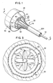
- Figure 1 is a perspective view of the distal end of apparatus according to the invention;
- Figure 2 is an enlarged sectional view taken along line 2-2 of Figure 1 and showing the device of Figure 1 in its operative state to pump blood to the being's vascular system; and
- Figure 3 is an enlarged sectional view taken along line 3-3 of Figure 2.
- As shown in Figure 1 apparatus (20) according to the invention is arranged to be disposed within the vascular system, and in particular, the aorta (22, Figure 2) to effect the pumping of blood through the vascular system. The apparatus comprises a catheter having pumping means (24) located at its distal end portion (26), i.e that end remote from the operator. The catheter comprises an elongated outer tube or sleeve (20A) of small diameter, e.g 5 to 10 French (1.7-3.3 mm), with various components located therein and with the pumping means (24) and barrier means, to be described later, at its distal end portion (26). The catheter is sufficiently flexible to enable it to be passed through the vascular system to its desired position within the aorta remote (i.e downstream) from the aortic valve (28) (Figure 2). The positioning of the catheter (20) is carried out through the use of a conventional tubular guide catheter (not shown), which is first introduced and threaded through the vascular system in a conventional manner. For example, the catheter (20) is inserted percutaneously into the femoral artery (not shown), up through the descending aorta (not shown) until its distal end portion (26) is located at a desired position within the aorta (22) downstream of the aortic valve (28) and downstream of the junction of the coronary arteries (30) to the aorta. Thus, the distal end portion (26) may be located within the ascending aorta, the aortic arch or the descending aorta, as desired.
- As shown best in Figure 2, the distal end portion (26) of the catheter (20) includes the pump means (24). That means can take various forms such as those disclosed in US-A-4,753,221. Thus, the pump means (24) is preferably a centrifugal pump which is arranged to be operated, e.g rotated, by drive means (32) shown. The drive means (32) can take various forms, but preferably comprises the high speed rotary drive system described and claimed in US-A-4,606,902 entitled Spiral Wire Bearing for Rotating Wire Drive Catheter, the disclosure of which is incorporated by reference herein. That drive system comprises an elongated drive wire or cable (32A) supported in the centre of the catheter tube (20A) along its central longitudinal axis (34), by means of a spiral bearing (32B). That bearing comprises a helical or spiral coil of wire extending substantially the entire length of the catheter tube from a proximately located point outside the body to the distal end portion of the catheter. The outer diameter of the helical bearing is sufficiently great so that its loops just clear the interior surface of the catheter tube (20A) to hold the bearing securely in place therein. The inside diameter of the central passage extending down the length of the helical bearing is just slightly greater than the outside diameter of the drive cable so the drive cable can rotate freely therein.
- In the interests of reducing the size of any wear debris created by the rotation of the drive cable within the spiral bearing, the drive cable may be swaged or drawn to increase the engaging surface area thereof, while the cross-sectional shape of the spiral bearing can be rectangular to also increase the engaging surface area.
- The drive cable is arranged to be connected at the proximal end thereof to an electric motor (not shown) or some other drive means for rotating the cable at high speed, e.g from 10,000 to 200,000 rpm, to effect the operation of the pump (24).
- The distal end portion of the catheter is of a generally tubular construction which is arranged to be expanded from a retracted orientation (not shown) to an expanded orientation (as shown in Figures 1 to 3), and vice versa. When the distal end portion is in the compact orientation its outside diameter is sufficiently small to enable the catheter to be readily inserted longitudinally into the aorta, via a percutaneous insertion at a desired location, e.g into the femoral artery. Once the catheter is within the aorta, and in particular at the desired position at which it is to be operated, the distal end portion is expanded to the expanded orientation shown in the drawings.
- The pump (24) is an expandable/contractible member so that when the distal end portion of the catheter is expanded, automatically expands from a closed or compact position to the open, operative position.
- In the embodiment shown herein the pump (24) is an axial type pump basically comprising a central hub (24A) from which four blades or impellers (24B) extend. The blades are biased to naturally project outward radially. However, the blades are formed of flexible material so that when the distal end portion of the catheter (20) is compacted (unexpanded) the blades are flexed into the closed or compressed position extending beside one another. When released or freed they extend radially outward from the hub (24A). Moreover each of the blades (24B) is angled so that when the pump is rotated about the central axis (34) of the catheter the blades (24B) draw blood from the heart into an inlet (to be described later) in the distal end portion of the catheter to the blades and from there the blades force the blood out of an outlet into the direction of arrows (to be described later) into the aorta (22).
- The proximal end of the hub (24A) is connected to the distal end of the drive cable (32A) so that the rotation of cable causes the concomitant rotation of pump's blades (24B).
- The edges of each of the blades (24B) are preferably rounded so as not to present any sharp edges which could adversely affect the blood cells pumped thereby.
- The pump (24) is held in position centered within the distal end portion by a bearing support (36).
- As can be seen the distal end portion of the catheter (20) is in the form of a cup-shaped member (38). The member (38) is formed of a flexible and/or resilient material, e.g an elastomeric material. The member (38) is tubular in shape, e.g it constitutes a truncated cone, including an enlarged diameter open ree end (40) located at the distal end thereof and a smaller diameter open end (42) located at the proximal end thereof. The cup-shaped member (38) is mounted on the sleeve (20A) forming the outer wall of the catheter at the distal end thereof via a plurality of resilient fingers (44). The fingers extend at equally spaced locations about the periphery of the catheter's sleeve (20A). Each finger (44) is formed of a resilient material and is slightly arcuate in shape. The distal end (46) of each of the fingers (44) is secured to the outer periphery of the cup-shaped member immediately adjacent the opening (42) while the proximal end (48) of each of the fingers (44) is fixed to the catheter sleeve (20A). Each of the fingers (44) is biased radially outward so that when unconstrained, they move to the expanded position shown in the drawings, thereby expanding the cup-shaped member (38) from a retracted or compacted orientation (not shown), in which it is somewhat like a folded umbrella, to the expanded orientation shown. The fingers (44) and the cup-shaped member (38) are arranged to be compressed or contracted radially inward by being disposed within the tubular guide and/or introducing catheter (not shown) during placement of the device (20) in the patient.
- In particular, the device is arranged to be inserted through a conventional tubular guide/introducing catheter into the body to the desired position within the aorta and the guide/introducing catheter is then retracted to expose the distal end portion of the device (20). This action enables the resilient fingers (44) to move radially outward to the position shown, thereby causing the cup-shaped member (38) to also assume the expanded orientation shown.
- In normal operation the flared open end (40) of the cup-shaped member (38) serves as the inlet to the pump (24), while the smaller diameter opening (42) and the open spaces (50) between the fingers (44) contiguous with the opening (42) serves as the outlet from the pump. Thus the pump is located so that its blades are disposed within the cup shaped member (38) between the inlet and the outlet.
- In order to ensure that substantially all, if not all, of the blood which will flow through the aorta flows into the pump's inlet (and not around the outside of the catheter), the distal end portion of the catheter includes the heretofore mentioned barrier means. That means is in the form of a barrier wall of a flexible skirt (62) which extends about the periphery of cupshaped member (38) contiguous with the opening (inlet) (40). The skirt is very flexible so that it engages and conforms to the periphery of the inner surface of the aorta as shown clearly in Figures 2 and 3. This action has the effect of isolating the portion of the aorta (22) upstream (distally) of the pump from the portion of the aorta downstream (proximally) of the pump, except for the passageway through the pump itself, i.e through the cup-shaped member (38) from the inlet to the outlet.
- Accordingly, when the pump is operated at a relatively high speed, e.g 10,000 to 100,000 rpm, higher pressure is produced in the aorta downstream of the barrier wall than upstream. This action causes blood to be drawn in the direction of arrows (54) from the heart (56) through the aortic valve (28) into the pump's inlet (40) from whence it flows to the pump's outlet (42, 50) and from there into the aorta (22) for passage to the remainder of the person's vascular system.
- In some applications, e.g to ensure that sufficient blood flows into the coronary arteries (30), the operation of the catheter's pump will be co-ordinated with the pumping action of the heart. Thus, for such applications the speed of the pump is cycled, i.e slowed down or stopped, in synchronism with the pumping action of the heart so that there will be repetitive periods when the higher pressure downstream of the pump pushes the blood upstream of the pump into the coronary arteries. The pump speed/time cycle can be established and/or adjusted to anything desired.
- Not only does the barrier wall (52) provide the isolation function described above, it also serves to hold the distal end of the catheter at the desired operative position within the aorta.
- As will be appreciated from the foregoing since the catheter is arranged to be located at a position remote from the heart and the aortic valve, it can be used by less skilled personnel than would otherwise be required if the catheter had to be located into the heart through the aortic valve or immediately over the aortic valve. Moreover, some medical situations, e.g a patient having a calcified aortic valve or whose heart has stopped beating, may not be conducive to the disposition of a catheter through or immediately over the aortic valve. It is for such applications that the subject catheter is particularly suited. Furthermore, the location of the distal end of the catheter remote from the aortic valve ensures that the entrance to the coronary arteries is not blocked by any portion of the catheter.
Claims (10)
Applications Claiming Priority (2)
| Application Number | Priority Date | Filing Date | Title |
|---|---|---|---|
| US257489 | 1988-10-13 | ||
| US07/257,489 US4919647A (en) | 1988-10-13 | 1988-10-13 | Aortically located blood pumping catheter and method of use |
Publications (2)
| Publication Number | Publication Date |
|---|---|
| EP0364293A2 true EP0364293A2 (en) | 1990-04-18 |
| EP0364293A3 EP0364293A3 (en) | 1991-03-06 |
Family
ID=22976513
Family Applications (1)
| Application Number | Title | Priority Date | Filing Date |
|---|---|---|---|
| EP19890310536 Withdrawn EP0364293A3 (en) | 1988-10-13 | 1989-10-13 | Blood pumping catheter |
Country Status (4)
| Country | Link |
|---|---|
| US (1) | US4919647A (en) |
| EP (1) | EP0364293A3 (en) |
| JP (1) | JPH02203867A (en) |
| CA (1) | CA2000505A1 (en) |
Cited By (46)
| Publication number | Priority date | Publication date | Assignee | Title |
|---|---|---|---|---|
| WO1993017747A1 (en) * | 1992-03-02 | 1993-09-16 | Kirkman Thomas R | Apparatus and method for retaining a catheter in a blood vessel in a fixed position |
| WO1994005347A1 (en) * | 1992-09-02 | 1994-03-17 | Reitan Oeyvind | Catheter pump |
| US5368438A (en) * | 1993-06-28 | 1994-11-29 | Baxter International Inc. | Blood pump |
| US5509900A (en) * | 1992-03-02 | 1996-04-23 | Kirkman; Thomas R. | Apparatus and method for retaining a catheter in a blood vessel in a fixed position |
| WO1997011737A1 (en) * | 1995-09-26 | 1997-04-03 | Fraunhofer-Gesellschaft zur Förderung der angewandten Forschung e.V. | System for actively supporting the flow of body fluids |
| EP0799060A1 (en) * | 1994-12-16 | 1997-10-08 | JARVIK, Robert K. | High reliability cardiac assist system |
| WO1997037697A1 (en) * | 1996-04-04 | 1997-10-16 | Rau Guenter | Intravascular blood pump |
| WO1999044651A1 (en) * | 1998-03-07 | 1999-09-10 | Guenther Rolf W | Self-deploying axial-flow pump introduced intravascularly for temporary cardiac support |
| EP1017430A1 (en) * | 1996-10-31 | 2000-07-12 | Inc. Momentum Medical | Modified circulatory assist device |
| US7393181B2 (en) | 2004-09-17 | 2008-07-01 | The Penn State Research Foundation | Expandable impeller pump |
| WO2010133567A1 (en) * | 2009-05-18 | 2010-11-25 | Cardiobridge Gmbh | Catheter pump |
| US7841976B2 (en) | 2006-03-23 | 2010-11-30 | Thoratec Corporation | Heart assist device with expandable impeller pump |
| EP2266640A1 (en) * | 2009-06-25 | 2010-12-29 | ECP Entwicklungsgesellschaft mbH | Compressible and expandable turbine blade for a fluid pump |
| EP2298374A1 (en) | 2007-10-08 | 2011-03-23 | Ais Gmbh Aachen Innovative Solutions | Catheter device |
| US7998054B2 (en) | 1997-10-09 | 2011-08-16 | Thoratec Corporation | Implantable heart assist system and method of applying same |
| EP2366412A2 (en) | 2007-10-08 | 2011-09-21 | Ais Gmbh Aachen Innovative Solutions | Catheter device |
| WO2012018917A1 (en) * | 2010-08-03 | 2012-02-09 | World Heart Corporation | Conformal cannula device and related methods |
| US8118724B2 (en) | 2003-09-18 | 2012-02-21 | Thoratec Corporation | Rotary blood pump |
| US8535211B2 (en) | 2009-07-01 | 2013-09-17 | Thoratec Corporation | Blood pump with expandable cannula |
| US8545380B2 (en) | 2006-09-14 | 2013-10-01 | Circulite, Inc. | Intravascular blood pump and catheter |
| US8579858B2 (en) | 2008-06-23 | 2013-11-12 | Cardiobridge Gmbh | Catheter pump for circulatory support |
| US8721517B2 (en) | 2012-05-14 | 2014-05-13 | Thoratec Corporation | Impeller for catheter pump |
| US9404505B2 (en) | 2008-12-05 | 2016-08-02 | Ecp Entwicklungsgesellschaft Mbh | Fluid pump with a rotor |
| US9416791B2 (en) | 2010-01-25 | 2016-08-16 | Ecp Entwicklungsgesellschaft Mbh | Fluid pump having a radially compressible rotor |
| US9512852B2 (en) | 2006-03-31 | 2016-12-06 | Thoratec Corporation | Rotary blood pump |
| US9545468B2 (en) | 1999-09-03 | 2017-01-17 | Maquet Cardiovascular Llc | Guidable intravascular blood pump and related methods |
| US9611743B2 (en) | 2010-07-15 | 2017-04-04 | Ecp Entwicklungsgesellschaft Mbh | Radially compressible and expandable rotor for a pump having an impeller blade |
| RU2619995C2 (en) * | 2011-08-17 | 2017-05-22 | Флоу Форвард Медикал, Инк. | Blood pump systems and methods |
| US9759237B2 (en) | 2010-05-17 | 2017-09-12 | Ecp Entwicklungsgesellschaft Mbh | Pump arrangement |
| US9771801B2 (en) | 2010-07-15 | 2017-09-26 | Ecp Entwicklungsgesellschaft Mbh | Rotor for a pump, produced with a first elastic material |
| US9833550B2 (en) | 2003-08-08 | 2017-12-05 | Abiomed Europe Gmbh | Intracardiac pumping device |
| US9872947B2 (en) | 2012-05-14 | 2018-01-23 | Tc1 Llc | Sheath system for catheter pump |
| US9878079B2 (en) | 2007-10-08 | 2018-01-30 | Ais Gmbh Aachen Innovative Solutions | Catheter device |
| US9903384B2 (en) | 2009-12-23 | 2018-02-27 | Ecp Entwicklungsgesellschaft Mbh | Radially compressible and expandable rotor for a fluid pump |
| WO2018118756A1 (en) * | 2016-12-19 | 2018-06-28 | Abiomed, Inc. | Heart pump with passive purge system |
| US10080871B2 (en) | 2012-12-21 | 2018-09-25 | Ecp Entwicklungsgesellschaft Mbh | Sheath assembly for insertion of a cord-shaped element, particularly a catheter, into the body of a patient |
| US10117980B2 (en) | 2012-05-14 | 2018-11-06 | Tc1 Llc | Distal bearing support |
| EP3446730A1 (en) * | 2017-08-23 | 2019-02-27 | ECP Entwicklungsgesellschaft mbH | Drive shaft cover with a heat conducting part |
| US10525238B2 (en) | 2011-12-22 | 2020-01-07 | Ecp Entwicklungsgesellschaft Mbh | Sheath device for inserting a catheter |
| US10576193B2 (en) | 2012-07-03 | 2020-03-03 | Tc1 Llc | Motor assembly for catheter pump |
| US10709828B2 (en) | 2011-12-22 | 2020-07-14 | Ecp Entwicklungsgesellschaft Mbh | Sheath device for inserting a catheter |
| US10874781B2 (en) | 2010-06-25 | 2020-12-29 | Ecp Entwicklungsgesellschaft Mbh | System for introducing a pump |
| US10874783B2 (en) | 2007-10-08 | 2020-12-29 | Ais Gmbh Aachen Innovative Solutions | Catheter device |
| US11077294B2 (en) | 2013-03-13 | 2021-08-03 | Tc1 Llc | Sheath assembly for catheter pump |
| US11219756B2 (en) | 2012-07-03 | 2022-01-11 | Tc1 Llc | Motor assembly for catheter pump |
| US11964119B2 (en) | 2021-02-18 | 2024-04-23 | Tc1 Llc | Sheath assembly for catheter pump |
Families Citing this family (158)
| Publication number | Priority date | Publication date | Assignee | Title |
|---|---|---|---|---|
| JPH0636821B2 (en) * | 1990-03-08 | 1994-05-18 | 健二 山崎 | Implantable auxiliary artificial heart |
| US5092844A (en) * | 1990-04-10 | 1992-03-03 | Mayo Foundation For Medical Education And Research | Intracatheter perfusion pump apparatus and method |
| US5163910A (en) * | 1990-04-10 | 1992-11-17 | Mayo Foundation For Medical Education And Research | Intracatheter perfusion pump apparatus and method |
| US5167628A (en) * | 1991-05-02 | 1992-12-01 | Boyles Paul W | Aortic balloon catheter assembly for indirect infusion of the coronary arteries |
| US5290227A (en) * | 1992-08-06 | 1994-03-01 | Pasque Michael K | Method of implanting blood pump in ascending aorta or main pulmonary artery |
| US5344443A (en) * | 1992-09-17 | 1994-09-06 | Rem Technologies, Inc. | Heart pump |
| CA2141522A1 (en) * | 1994-02-16 | 1995-08-17 | Thomas D. Weldon | Electrophysiology positioning catheter |
| US6723069B1 (en) | 1994-02-16 | 2004-04-20 | Novoste Corporation | Electrophysiology positioning catheter |
| US5738627A (en) * | 1994-08-18 | 1998-04-14 | Duke University | Bi-ventricular cardiac assist device |
| US5643215A (en) * | 1995-02-24 | 1997-07-01 | The Research Foundation Of State University Of New York | Gas exchange apparatus and method |
| DE19613564C1 (en) | 1996-04-04 | 1998-01-08 | Guenter Prof Dr Rau | Intravascular blood pump |
| US5911685A (en) * | 1996-04-03 | 1999-06-15 | Guidant Corporation | Method and apparatus for cardiac blood flow assistance |
| US5964694A (en) * | 1997-04-02 | 1999-10-12 | Guidant Corporation | Method and apparatus for cardiac blood flow assistance |
| US6048363A (en) * | 1997-05-13 | 2000-04-11 | Nagyszalanczy; Lorant | Centrifugal blood pump apparatus |
| US6228046B1 (en) * | 1997-06-02 | 2001-05-08 | Pharmasonics, Inc. | Catheters comprising a plurality of oscillators and methods for their use |
| US6123725A (en) * | 1997-07-11 | 2000-09-26 | A-Med Systems, Inc. | Single port cardiac support apparatus |
| US7182727B2 (en) * | 1997-07-11 | 2007-02-27 | A—Med Systems Inc. | Single port cardiac support apparatus |
| US6176822B1 (en) | 1998-03-31 | 2001-01-23 | Impella Cardiotechnik Gmbh | Intracardiac blood pump |
| US6086527A (en) * | 1998-04-02 | 2000-07-11 | Scimed Life Systems, Inc. | System for treating congestive heart failure |
| US6110100A (en) * | 1998-04-22 | 2000-08-29 | Scimed Life Systems, Inc. | System for stress relieving the heart muscle and for controlling heart function |
| AU754594B2 (en) * | 1998-04-24 | 2002-11-21 | Indigo Medical, Incorporated | Energy application system with ancillary information exchange capability, energy applicator, and methods associated therewith |
| US7780628B1 (en) | 1999-01-11 | 2010-08-24 | Angiodynamics, Inc. | Apparatus and methods for treating congestive heart disease |
| US7329236B2 (en) * | 1999-01-11 | 2008-02-12 | Flowmedica, Inc. | Intra-aortic renal drug delivery catheter |
| US7481803B2 (en) * | 2000-11-28 | 2009-01-27 | Flowmedica, Inc. | Intra-aortic renal drug delivery catheter |
| US6749598B1 (en) * | 1999-01-11 | 2004-06-15 | Flowmedica, Inc. | Apparatus and methods for treating congestive heart disease |
| US7122019B1 (en) | 2000-11-28 | 2006-10-17 | Flowmedica Inc. | Intra-aortic renal drug delivery catheter |
| US20050196293A1 (en) * | 1999-04-23 | 2005-09-08 | Ayre Peter J. | Rotary blood pump and control system therefor |
| AUPP995999A0 (en) * | 1999-04-23 | 1999-05-20 | University Of Technology, Sydney | Non-contact estimation and control system |
| JP2001070438A (en) * | 1999-09-02 | 2001-03-21 | Sentan Kagaku Gijutsu Incubation Center:Kk | Precision screw pump for living body |
| AU7354400A (en) * | 1999-09-03 | 2001-04-10 | A-Med Systems, Inc. | Guidable intravascular blood pump and related methods |
| US6592612B1 (en) * | 2000-05-04 | 2003-07-15 | Cardeon Corporation | Method and apparatus for providing heat exchange within a catheter body |
| WO2003103745A2 (en) * | 2002-06-11 | 2003-12-18 | Walid Aboul-Hosn | Expandable blood pump and related methods |
| AU2003294226A1 (en) * | 2002-09-20 | 2004-04-23 | Flowmedica, Inc. | Method and apparatus for intra aortic substance delivery to a branch vessel |
| EP1624909A2 (en) * | 2002-09-20 | 2006-02-15 | FlowMedica, Inc. | Appartus and method for inserting an intra-aorta catheter trough a delivery sheath |
| JP2006508776A (en) * | 2002-09-20 | 2006-03-16 | フローメディカ,インコーポレイテッド | Method and apparatus for selective substance delivery via an intrarenal catheter |
| US20050197624A1 (en) * | 2004-03-04 | 2005-09-08 | Flowmedica, Inc. | Sheath for use in peripheral interventions |
| US7063679B2 (en) | 2002-09-20 | 2006-06-20 | Flowmedica, Inc. | Intra-aortic renal delivery catheter |
| US7993325B2 (en) | 2002-09-20 | 2011-08-09 | Angio Dynamics, Inc. | Renal infusion systems and methods |
| EP1635736A2 (en) * | 2003-06-05 | 2006-03-22 | FlowMedica, Inc. | Systems and methods for performing bi-lateral interventions or diagnosis in branched body lumens |
| US20060167437A1 (en) * | 2003-06-17 | 2006-07-27 | Flowmedica, Inc. | Method and apparatus for intra aortic substance delivery to a branch vessel |
| WO2005016165A1 (en) * | 2003-08-05 | 2005-02-24 | Flowmedica, Inc. | System and method for prevention of radiocontrast induced nephropathy |
| US7494477B2 (en) * | 2003-09-02 | 2009-02-24 | Pulsecath B.V. | Catheter pump, catheter and fittings therefore and methods of using a catheter pump |
| US7811221B2 (en) * | 2004-02-10 | 2010-10-12 | Yossi Gross | Extracardiac blood flow amplification device |
| JP2007537298A (en) * | 2004-05-14 | 2007-12-20 | フロウメディカ, インコーポレイテッド | Bilateral local renal delivery for the treatment of congestive heart failure and BNP therapy |
| EP1789112B1 (en) * | 2004-08-13 | 2010-09-29 | Delgado, Reynolds M., III | Apparatus for long-term assisting a left ventricle to pump blood |
| US20060069323A1 (en) * | 2004-09-24 | 2006-03-30 | Flowmedica, Inc. | Systems and methods for bi-lateral guidewire cannulation of branched body lumens |
| DE102004054714A1 (en) * | 2004-11-12 | 2006-05-24 | Impella Cardiosystems Gmbh | Foldable intravascular insertable blood pump |
| US7972122B2 (en) * | 2005-04-29 | 2011-07-05 | Heartware, Inc. | Multiple rotor, wide blade, axial flow pump |
| US8419609B2 (en) | 2005-10-05 | 2013-04-16 | Heartware Inc. | Impeller for a rotary ventricular assist device |
| US7544160B2 (en) * | 2005-02-10 | 2009-06-09 | Yossi Gross | Extracardiac blood flow amplification device |
| US7479102B2 (en) * | 2005-02-28 | 2009-01-20 | Robert Jarvik | Minimally invasive transvalvular ventricular assist device |
| US7878967B1 (en) * | 2005-10-06 | 2011-02-01 | Sanjaya Khanal | Heart failure/hemodynamic device |
| EP1933920A4 (en) * | 2005-10-11 | 2010-12-29 | Flowmedica Inc | Vascular sheath with variable lumen construction |
| CA2636418A1 (en) | 2006-01-13 | 2007-07-26 | Heartware, Inc. | Rotary blood pump |
| US8672611B2 (en) | 2006-01-13 | 2014-03-18 | Heartware, Inc. | Stabilizing drive for contactless rotary blood pump impeller |
| WO2007132449A2 (en) * | 2006-05-11 | 2007-11-22 | Yossi Gross | Implantable respiration therapy device |
| US7771401B2 (en) * | 2006-06-08 | 2010-08-10 | Angiodynamics, Inc. | Selective renal cannulation and infusion systems and methods |
| US7914436B1 (en) | 2006-06-12 | 2011-03-29 | Abiomed, Inc. | Method and apparatus for pumping blood |
| US9028392B2 (en) * | 2006-12-01 | 2015-05-12 | NuCardia, Inc. | Medical device |
| WO2008079828A2 (en) | 2006-12-20 | 2008-07-03 | Onset Medical Corporation | Expandable trans-septal sheath |
| US20090112312A1 (en) | 2007-02-26 | 2009-04-30 | Larose Jeffrey A | Intravascular ventricular assist device |
| WO2008112563A1 (en) * | 2007-03-09 | 2008-09-18 | Flowmedica, Inc. | Acute kidney injury treatment systems and methods |
| US7828710B2 (en) * | 2007-06-05 | 2010-11-09 | Medical Value Partners, Llc | Apparatus comprising a drive cable for a medical device |
| US8079948B2 (en) * | 2007-08-29 | 2011-12-20 | NuCardia, Inc. | Article comprising an impeller |
| US20090105799A1 (en) * | 2007-10-23 | 2009-04-23 | Flowmedica, Inc. | Renal assessment systems and methods |
| WO2009091965A1 (en) * | 2008-01-18 | 2009-07-23 | Med Institute, Inc. | Intravascular device attachment system having tubular expandable body |
| US8562559B2 (en) | 2008-05-14 | 2013-10-22 | Onset Medical Corporation | Expandable iliac sheath and method of use |
| US9440054B2 (en) | 2008-05-14 | 2016-09-13 | Onset Medical Corporation | Expandable transapical sheath and method of use |
| WO2009157408A1 (en) | 2008-06-23 | 2009-12-30 | テルモ株式会社 | Blood pump apparatus |
| US9067005B2 (en) | 2008-12-08 | 2015-06-30 | Thoratec Corporation | Centrifugal pump apparatus |
| EP2216059A1 (en) | 2009-02-04 | 2010-08-11 | ECP Entwicklungsgesellschaft mbH | Catheter device with a catheter and an actuation device |
| JP5378010B2 (en) | 2009-03-05 | 2013-12-25 | ソラテック コーポレーション | Centrifugal pump device |
| CN102341600B (en) | 2009-03-06 | 2014-12-10 | 胸腔科技有限公司 | Centrifugal pump device |
| EP2229965A1 (en) | 2009-03-18 | 2010-09-22 | ECP Entwicklungsgesellschaft mbH | Fluid pump with particular form of a rotor blade |
| EP2246078A1 (en) | 2009-04-29 | 2010-11-03 | ECP Entwicklungsgesellschaft mbH | Shaft assembly with a shaft which moves within a fluid-filled casing |
| EP2248544A1 (en) | 2009-05-05 | 2010-11-10 | ECP Entwicklungsgesellschaft mbH | Fluid pump with variable circumference, particularly for medical use |
| EP3632485B1 (en) | 2009-05-11 | 2024-01-03 | Mayo Foundation for Medical Education and Research | Treating congestive heart failure |
| JP5656835B2 (en) | 2009-07-29 | 2015-01-21 | ソーラテック コーポレイション | Rotation drive device and centrifugal pump device using the same |
| EP2282070B1 (en) | 2009-08-06 | 2012-10-17 | ECP Entwicklungsgesellschaft mbH | Catheter device with a coupling device for a drive device |
| EP2299119B1 (en) | 2009-09-22 | 2018-11-07 | ECP Entwicklungsgesellschaft mbH | Inflatable rotor for a fluid pump |
| EP2298372A1 (en) | 2009-09-22 | 2011-03-23 | ECP Entwicklungsgesellschaft mbH | Rotor for an axial pump for transporting a fluid |
| EP2298371A1 (en) | 2009-09-22 | 2011-03-23 | ECP Entwicklungsgesellschaft mbH | Function element, in particular fluid pump with a housing and a transport element |
| EP2298373A1 (en) | 2009-09-22 | 2011-03-23 | ECP Entwicklungsgesellschaft mbH | Fluid pump with at least one turbine blade and a seating device |
| EP2314331B1 (en) | 2009-10-23 | 2013-12-11 | ECP Entwicklungsgesellschaft mbH | Catheter pump arrangement and flexible shaft arrangement with a cable core |
| EP2314330A1 (en) | 2009-10-23 | 2011-04-27 | ECP Entwicklungsgesellschaft mbH | Flexible shaft arrangement |
| US8690749B1 (en) | 2009-11-02 | 2014-04-08 | Anthony Nunez | Wireless compressible heart pump |
| EP2338539A1 (en) | 2009-12-23 | 2011-06-29 | ECP Entwicklungsgesellschaft mbH | Pump device with a detection device |
| EP2338540A1 (en) | 2009-12-23 | 2011-06-29 | ECP Entwicklungsgesellschaft mbH | Delivery blade for a compressible rotor |
| JP5443197B2 (en) | 2010-02-16 | 2014-03-19 | ソラテック コーポレーション | Centrifugal pump device |
| EP2363157A1 (en) | 2010-03-05 | 2011-09-07 | ECP Entwicklungsgesellschaft mbH | Device for exerting mechanical force on a medium, in particular fluid pump |
| WO2011118325A1 (en) | 2010-03-26 | 2011-09-29 | テルモ株式会社 | Centrifugal blood pump device |
| JP5681403B2 (en) | 2010-07-12 | 2015-03-11 | ソーラテック コーポレイション | Centrifugal pump device |
| EP2407187A3 (en) | 2010-07-15 | 2012-06-20 | ECP Entwicklungsgesellschaft mbH | Blood pump for invasive application within the body of a patient |
| EP2422735A1 (en) | 2010-08-27 | 2012-02-29 | ECP Entwicklungsgesellschaft mbH | Implantable blood transportation device, manipulation device and coupling device |
| JP5577506B2 (en) | 2010-09-14 | 2014-08-27 | ソーラテック コーポレイション | Centrifugal pump device |
| US8485961B2 (en) | 2011-01-05 | 2013-07-16 | Thoratec Corporation | Impeller housing for percutaneous heart pump |
| US8597170B2 (en) * | 2011-01-05 | 2013-12-03 | Thoratec Corporation | Catheter pump |
| WO2012094641A2 (en) | 2011-01-06 | 2012-07-12 | Thoratec Corporation | Percutaneous heart pump |
| US8591393B2 (en) | 2011-01-06 | 2013-11-26 | Thoratec Corporation | Catheter pump |
| EP2497521A1 (en) | 2011-03-10 | 2012-09-12 | ECP Entwicklungsgesellschaft mbH | Push device for axial insertion of a string-shaped, flexible body |
| WO2012132850A1 (en) | 2011-03-28 | 2012-10-04 | Ntn株式会社 | Rotation and drive device and centrifugal pump device using same |
| EP2564771A1 (en) | 2011-09-05 | 2013-03-06 | ECP Entwicklungsgesellschaft mbH | Medicinal product with a functional element for invasive use in the body of a patient |
| US8926492B2 (en) | 2011-10-11 | 2015-01-06 | Ecp Entwicklungsgesellschaft Mbh | Housing for a functional element |
| EP2785391B1 (en) | 2011-11-28 | 2015-09-23 | Mi-vad, Inc. | Ventricular assist device and method |
| JP6083929B2 (en) | 2012-01-18 | 2017-02-22 | ソーラテック コーポレイション | Centrifugal pump device |
| EP2830675A4 (en) | 2012-03-26 | 2016-01-27 | Procyrion Inc | Systems and methods for fluid flows and/or pressures for circulation and perfusion enhancement |
| EP2662099B1 (en) | 2012-05-09 | 2014-09-10 | Abiomed Europe GmbH | Intravascular blood pump |
| EP4218887A1 (en) | 2012-05-14 | 2023-08-02 | Tc1 Llc | Mechanical circulatory support device for stabilizing a patient after cardiogenic shock |
| US9327067B2 (en) | 2012-05-14 | 2016-05-03 | Thoratec Corporation | Impeller for catheter pump |
| CN108742951B (en) | 2012-06-06 | 2021-05-25 | 洋红医疗有限公司 | Artificial kidney valve |
| US9358329B2 (en) | 2012-07-03 | 2016-06-07 | Thoratec Corporation | Catheter pump |
| US9636441B2 (en) | 2012-11-05 | 2017-05-02 | Robert Jarvik | Support stent for transvalvular conduit |
| US9371826B2 (en) | 2013-01-24 | 2016-06-21 | Thoratec Corporation | Impeller position compensation using field oriented control |
| US9556873B2 (en) | 2013-02-27 | 2017-01-31 | Tc1 Llc | Startup sequence for centrifugal pump with levitated impeller |
| US10583231B2 (en) | 2013-03-13 | 2020-03-10 | Magenta Medical Ltd. | Blood pump |
| AU2014229150B2 (en) | 2013-03-13 | 2018-02-22 | Magenta Medical Ltd. | Renal pump |
| EP3834876B1 (en) | 2013-03-13 | 2022-09-14 | Tc1 Llc | Fluid handling system |
| US11033728B2 (en) | 2013-03-13 | 2021-06-15 | Tc1 Llc | Fluid handling system |
| EP3797810A1 (en) | 2013-03-15 | 2021-03-31 | Tc1 Llc | Catheter pump assembly including a stator |
| US9308302B2 (en) * | 2013-03-15 | 2016-04-12 | Thoratec Corporation | Catheter pump assembly including a stator |
| US9713663B2 (en) | 2013-04-30 | 2017-07-25 | Tc1 Llc | Cardiac pump with speed adapted for ventricle unloading |
| US10052420B2 (en) | 2013-04-30 | 2018-08-21 | Tc1 Llc | Heart beat identification and pump speed synchronization |
| US9764113B2 (en) | 2013-12-11 | 2017-09-19 | Magenta Medical Ltd | Curved catheter |
| EP3110468B1 (en) | 2014-02-25 | 2021-11-03 | Kushwaha, Sudhir | Ventricular assist device and method |
| WO2015160943A1 (en) | 2014-04-15 | 2015-10-22 | Thoratec Corporation | Sensors for catheter pumps |
| WO2015160942A1 (en) | 2014-04-15 | 2015-10-22 | Thoratec Corporation | Catheter pump with off-set motor position |
| EP3131599B1 (en) | 2014-04-15 | 2019-02-20 | Tc1 Llc | Catheter pump with access ports |
| US10105475B2 (en) | 2014-04-15 | 2018-10-23 | Tc1 Llc | Catheter pump introducer systems and methods |
| US10449279B2 (en) | 2014-08-18 | 2019-10-22 | Tc1 Llc | Guide features for percutaneous catheter pump |
| US9623161B2 (en) | 2014-08-26 | 2017-04-18 | Tc1 Llc | Blood pump and method of suction detection |
| US9675738B2 (en) | 2015-01-22 | 2017-06-13 | Tc1 Llc | Attachment mechanisms for motor of catheter pump |
| EP3247420B1 (en) | 2015-01-22 | 2019-10-02 | Tc1 Llc | Reduced rotational mass motor assembly for catheter pump |
| EP3247421B1 (en) | 2015-01-22 | 2019-10-02 | Tc1 Llc | Motor assembly with heat exchanger for catheter pump |
| WO2016130846A1 (en) | 2015-02-11 | 2016-08-18 | Thoratec Corporation | Heart beat identification and pump speed synchronization |
| US10371152B2 (en) | 2015-02-12 | 2019-08-06 | Tc1 Llc | Alternating pump gaps |
| EP3256185B1 (en) | 2015-02-12 | 2019-10-30 | Tc1 Llc | System and method for controlling the position of a levitated rotor |
| EP3256184B1 (en) | 2015-02-13 | 2020-04-08 | Tc1 Llc | Impeller suspension mechanism for heart pump |
| US9907890B2 (en) | 2015-04-16 | 2018-03-06 | Tc1 Llc | Catheter pump with positioning brace |
| WO2016185473A1 (en) | 2015-05-18 | 2016-11-24 | Magenta Medical Ltd. | Blood pump |
| US10117983B2 (en) | 2015-11-16 | 2018-11-06 | Tc1 Llc | Pressure/flow characteristic modification of a centrifugal pump in a ventricular assist device |
| EP3487550B1 (en) | 2016-07-21 | 2022-09-28 | Tc1 Llc | Gas-filled chamber for catheter pump motor assembly |
| EP3487549B1 (en) | 2016-07-21 | 2021-02-24 | Tc1 Llc | Fluid seals for catheter pump motor assembly |
| EP3518825B1 (en) | 2016-09-29 | 2020-05-27 | Magenta Medical Ltd. | Blood vessel tube |
| EP3556409B1 (en) | 2016-10-25 | 2022-01-05 | Magenta Medical Ltd. | Ventricular assist device |
| CN110049792B (en) | 2016-11-23 | 2022-01-18 | 马真塔医药有限公司 | Blood pump |
| EP4233989A3 (en) | 2017-06-07 | 2023-10-11 | Shifamed Holdings, LLC | Intravascular fluid movement devices, systems, and methods of use |
| EP3710076B1 (en) | 2017-11-13 | 2023-12-27 | Shifamed Holdings, LLC | Intravascular fluid movement devices, systems, and methods of use |
| US10905808B2 (en) | 2018-01-10 | 2021-02-02 | Magenta Medical Ltd. | Drive cable for use with a blood pump |
| EP3854444A1 (en) | 2018-01-10 | 2021-07-28 | Magenta Medical Ltd. | Distal tip element for blood pump |
| JP7410034B2 (en) | 2018-02-01 | 2024-01-09 | シファメド・ホールディングス・エルエルシー | Intravascular blood pump and methods of use and manufacture |
| US10893927B2 (en) | 2018-03-29 | 2021-01-19 | Magenta Medical Ltd. | Inferior vena cava blood-flow implant |
| EP3810219A2 (en) | 2018-06-25 | 2021-04-28 | Ballout, Bashar | Percutaneous blood pump and introducer system |
| EP3782665B1 (en) | 2019-01-24 | 2021-08-25 | Magenta Medical Ltd. | Ventricular assist device |
| WO2021016372A1 (en) | 2019-07-22 | 2021-01-28 | Shifamed Holdings, Llc | Intravascular blood pumps with struts and methods of use and manufacture |
| US11724089B2 (en) | 2019-09-25 | 2023-08-15 | Shifamed Holdings, Llc | Intravascular blood pump systems and methods of use and control thereof |
| EP4069347A4 (en) | 2019-12-03 | 2023-12-27 | Procyrion, Inc. | Blood pumps |
| WO2021119413A1 (en) * | 2019-12-13 | 2021-06-17 | Procyrion, Inc. | Support structures for intravascular blood pumps |
| TW202241538A (en) * | 2021-03-11 | 2022-11-01 | 德商阿比奥梅德歐洲有限公司 | Pump including a compressible rotor having offset rotor blades |
Citations (3)
| Publication number | Priority date | Publication date | Assignee | Title |
|---|---|---|---|---|
| US3592184A (en) * | 1969-12-16 | 1971-07-13 | David H Watkins | Heart assist method and catheter |
| WO1985001432A1 (en) * | 1983-09-28 | 1985-04-11 | Nimbus, Inc. | High-capacity intravascular blood pump utilizing percutaneous access |
| US4753221A (en) * | 1986-10-22 | 1988-06-28 | Intravascular Surgical Instruments, Inc. | Blood pumping catheter and method of use |
Family Cites Families (2)
| Publication number | Priority date | Publication date | Assignee | Title |
|---|---|---|---|---|
| US4688998A (en) * | 1981-03-18 | 1987-08-25 | Olsen Don B | Magnetically suspended and rotated impellor pump apparatus and method |
| US4686982A (en) * | 1985-06-19 | 1987-08-18 | John Nash | Spiral wire bearing for rotating wire drive catheter |
-
1988
- 1988-10-13 US US07/257,489 patent/US4919647A/en not_active Expired - Fee Related
-
1989
- 1989-10-11 CA CA002000505A patent/CA2000505A1/en not_active Abandoned
- 1989-10-13 JP JP1267962A patent/JPH02203867A/en active Pending
- 1989-10-13 EP EP19890310536 patent/EP0364293A3/en not_active Withdrawn
Patent Citations (3)
| Publication number | Priority date | Publication date | Assignee | Title |
|---|---|---|---|---|
| US3592184A (en) * | 1969-12-16 | 1971-07-13 | David H Watkins | Heart assist method and catheter |
| WO1985001432A1 (en) * | 1983-09-28 | 1985-04-11 | Nimbus, Inc. | High-capacity intravascular blood pump utilizing percutaneous access |
| US4753221A (en) * | 1986-10-22 | 1988-06-28 | Intravascular Surgical Instruments, Inc. | Blood pumping catheter and method of use |
Cited By (145)
| Publication number | Priority date | Publication date | Assignee | Title |
|---|---|---|---|---|
| US6071263A (en) * | 1992-03-02 | 2000-06-06 | Kirkman; Thomas R. | Apparatus and method for retaining a catheter in a blood vessel in a fixed position |
| US5509900A (en) * | 1992-03-02 | 1996-04-23 | Kirkman; Thomas R. | Apparatus and method for retaining a catheter in a blood vessel in a fixed position |
| WO1993017747A1 (en) * | 1992-03-02 | 1993-09-16 | Kirkman Thomas R | Apparatus and method for retaining a catheter in a blood vessel in a fixed position |
| US6558349B1 (en) | 1992-03-02 | 2003-05-06 | Thomas R. Kirkman | Apparatus and method for retaining a catheter in a blood vessel in a fixed position |
| WO1994005347A1 (en) * | 1992-09-02 | 1994-03-17 | Reitan Oeyvind | Catheter pump |
| US5749855A (en) * | 1992-09-02 | 1998-05-12 | Reitan; Oyvind | Catheter pump |
| US5368438A (en) * | 1993-06-28 | 1994-11-29 | Baxter International Inc. | Blood pump |
| EP0799060A4 (en) * | 1994-12-16 | 2002-07-17 | Robert K Jarvik | High reliability cardiac assist system |
| EP0799060A1 (en) * | 1994-12-16 | 1997-10-08 | JARVIK, Robert K. | High reliability cardiac assist system |
| WO1997011737A1 (en) * | 1995-09-26 | 1997-04-03 | Fraunhofer-Gesellschaft zur Förderung der angewandten Forschung e.V. | System for actively supporting the flow of body fluids |
| WO1997037697A1 (en) * | 1996-04-04 | 1997-10-16 | Rau Guenter | Intravascular blood pump |
| EP1017430A1 (en) * | 1996-10-31 | 2000-07-12 | Inc. Momentum Medical | Modified circulatory assist device |
| EP1017430A4 (en) * | 1996-10-31 | 2001-03-14 | Medical Inc Momentum | Modified circulatory assist device |
| US7998054B2 (en) | 1997-10-09 | 2011-08-16 | Thoratec Corporation | Implantable heart assist system and method of applying same |
| WO1999044651A1 (en) * | 1998-03-07 | 1999-09-10 | Guenther Rolf W | Self-deploying axial-flow pump introduced intravascularly for temporary cardiac support |
| US10357598B2 (en) | 1999-09-03 | 2019-07-23 | Maquet Cardiovascular Llc | Guidable intravascular blood pump and related methods |
| US9789238B2 (en) | 1999-09-03 | 2017-10-17 | Maquet Cardiovascular, Llc | Guidable intravascular blood pump and related methods |
| US9545468B2 (en) | 1999-09-03 | 2017-01-17 | Maquet Cardiovascular Llc | Guidable intravascular blood pump and related methods |
| US9561314B2 (en) | 1999-09-03 | 2017-02-07 | Maquet Cardiovascular Llc | Guidable intravascular blood pump and related methods |
| US10238783B2 (en) | 1999-09-03 | 2019-03-26 | Maquet Cardiovascular Llc | Guidable intravascular blood pump and related methods |
| US9597437B2 (en) | 1999-09-03 | 2017-03-21 | Maquet Cardiovascular Llc | Guidable intravascular blood pump and related methods |
| US10300186B2 (en) | 1999-09-03 | 2019-05-28 | Maquet Cardiovascular Llc | Guidable intravascular blood pump and related methods |
| US10328191B2 (en) | 1999-09-03 | 2019-06-25 | Maquet Cardiovascular Llc | Guidable intravascular blood pump and related methods |
| US10300185B2 (en) | 1999-09-03 | 2019-05-28 | Maquet Cardiovascular Llc | Guidable intravascular blood pump and related methods |
| US10279095B2 (en) | 1999-09-03 | 2019-05-07 | Maquet Cardiovascular Llc | Guidable intravascular blood pump and related methods |
| US10322218B2 (en) | 1999-09-03 | 2019-06-18 | Maquet Cardiovascular Llc | Guidable intravascular blood pump and related methods |
| US9872948B2 (en) | 2003-08-08 | 2018-01-23 | Abiomed Europe Gmbh | Intracardiac pumping device |
| US11491320B2 (en) | 2003-08-08 | 2022-11-08 | Abiomed Europe Gmbh | Intracardiac pumping device |
| US9833550B2 (en) | 2003-08-08 | 2017-12-05 | Abiomed Europe Gmbh | Intracardiac pumping device |
| US8118724B2 (en) | 2003-09-18 | 2012-02-21 | Thoratec Corporation | Rotary blood pump |
| US8684902B2 (en) | 2003-09-18 | 2014-04-01 | Thoratec Corporation | Rotary blood pump |
| US11434921B2 (en) | 2004-09-17 | 2022-09-06 | Tc1 Llc | Expandable impeller pump |
| US7927068B2 (en) | 2004-09-17 | 2011-04-19 | Thoratec Corporation | Expandable impeller pump |
| EP3792500A1 (en) * | 2004-09-17 | 2021-03-17 | The Penn State Research Foundation | Expandable impeller pump |
| EP4194702A1 (en) * | 2004-09-17 | 2023-06-14 | The Penn State Research Foundation | Expandable impeller pump |
| US11428236B2 (en) | 2004-09-17 | 2022-08-30 | Tc1 Llc | Expandable impeller pump |
| US9717833B2 (en) | 2004-09-17 | 2017-08-01 | The Penn State Research Foundation | Heart assist device with expandable impeller pump |
| US7393181B2 (en) | 2004-09-17 | 2008-07-01 | The Penn State Research Foundation | Expandable impeller pump |
| US7841976B2 (en) | 2006-03-23 | 2010-11-30 | Thoratec Corporation | Heart assist device with expandable impeller pump |
| AU2007230945B2 (en) * | 2006-03-23 | 2013-05-02 | The Penn State Research Foundation | Heart assist device with expandable impeller pump |
| US10864309B2 (en) | 2006-03-23 | 2020-12-15 | The Penn State Research Foundation | Heart assist device with expandable impeller pump |
| US10149932B2 (en) | 2006-03-23 | 2018-12-11 | The Penn State Research Foundation | Heart assist device with expandable impeller pump |
| US11708833B2 (en) | 2006-03-23 | 2023-07-25 | The Penn State Research Foundation | Heart assist device with expandable impeller pump |
| US9512852B2 (en) | 2006-03-31 | 2016-12-06 | Thoratec Corporation | Rotary blood pump |
| US8545380B2 (en) | 2006-09-14 | 2013-10-01 | Circulite, Inc. | Intravascular blood pump and catheter |
| EP2298374A1 (en) | 2007-10-08 | 2011-03-23 | Ais Gmbh Aachen Innovative Solutions | Catheter device |
| US10980927B2 (en) | 2007-10-08 | 2021-04-20 | Ais Gmbh Aachen Innovative Solutions | Catheter device |
| EP3000492A1 (en) | 2007-10-08 | 2016-03-30 | Ais Gmbh Aachen Innovative Solutions | Catheter device |
| DE202008018612U1 (en) | 2007-10-08 | 2016-10-06 | Ais Gmbh Aachen Innovative Solutions | Catheter device |
| DE202008018622U1 (en) | 2007-10-08 | 2016-11-03 | Ais Gmbh Aachen Innovative Solutions | Catheter device |
| EP3000493A1 (en) | 2007-10-08 | 2016-03-30 | Ais Gmbh Aachen Innovative Solutions | Catheter device |
| US10894115B2 (en) | 2007-10-08 | 2021-01-19 | Ais Gmbh Aachen Innovative Solutions | Catheter device |
| DE202008018576U1 (en) | 2007-10-08 | 2015-12-11 | Ais Gmbh Aachen Innovative Solutions | Catheter device |
| DE202008018578U1 (en) | 2007-10-08 | 2015-12-10 | Ais Gmbh Aachen Innovative Solutions | Catheter device |
| DE202008018575U1 (en) | 2007-10-08 | 2015-12-10 | Ais Gmbh Aachen Innovative Solutions | Catheter device |
| US10874783B2 (en) | 2007-10-08 | 2020-12-29 | Ais Gmbh Aachen Innovative Solutions | Catheter device |
| US11123539B2 (en) | 2007-10-08 | 2021-09-21 | Ais Gmbh Aachen Innovative Solutions | Catheter device |
| EP3187210A1 (en) | 2007-10-08 | 2017-07-05 | Ais Gmbh Aachen Innovative Solutions | Catheter device |
| US11129978B2 (en) | 2007-10-08 | 2021-09-28 | Ais Gmbh Aachen Innovative Solutions | Catheter device |
| US10799624B2 (en) | 2007-10-08 | 2020-10-13 | Ais Gmbh Aachen Innovative Solutions | Catheter device |
| EP3216467A1 (en) | 2007-10-08 | 2017-09-13 | Ais Gmbh Aachen Innovative Solutions | Catheter device |
| US10478539B2 (en) | 2007-10-08 | 2019-11-19 | Ais Gmbh Aachen Innovative Solutions | Catheter device |
| US11167124B2 (en) | 2007-10-08 | 2021-11-09 | Ais Gmbh Aachen Innovative Solutions | Catheter device |
| US11253693B2 (en) | 2007-10-08 | 2022-02-22 | Ais Gmbh Aachen Innovative Solutions | Catheter device |
| US10449276B2 (en) | 2007-10-08 | 2019-10-22 | Ais Gmbh Aachen Innovative Solutions | Catheter device |
| US11273301B2 (en) | 2007-10-08 | 2022-03-15 | Ais Gmbh Aachen Innovative Solutions | Catheter device |
| US9878079B2 (en) | 2007-10-08 | 2018-01-30 | Ais Gmbh Aachen Innovative Solutions | Catheter device |
| US9889242B2 (en) | 2007-10-08 | 2018-02-13 | Ais Gmbh Aachen Innovative Solutions | Catheter device |
| US11338124B2 (en) | 2007-10-08 | 2022-05-24 | Ais Gmbh Aachen Innovative Solutions | Catheter device |
| US11583659B2 (en) | 2007-10-08 | 2023-02-21 | Ais Gmbh Aachen Innovative Solutions | Catheter device |
| EP2366412A2 (en) | 2007-10-08 | 2011-09-21 | Ais Gmbh Aachen Innovative Solutions | Catheter device |
| EP2345440A1 (en) | 2007-10-08 | 2011-07-20 | Ais Gmbh Aachen Innovative Solutions | Catheter device |
| EP2308524A1 (en) | 2007-10-08 | 2011-04-13 | Ais Gmbh Aachen Innovative Solutions | Catheter device |
| EP2301598A1 (en) | 2007-10-08 | 2011-03-30 | Ais Gmbh Aachen Innovative Solutions | Catheter device |
| EP3427770A1 (en) | 2007-10-08 | 2019-01-16 | Ais Gmbh Aachen Innovative Solutions | Catheter device |
| EP3431115A1 (en) | 2007-10-08 | 2019-01-23 | Ais Gmbh Aachen Innovative Solutions | Catheter device |
| US11786700B2 (en) | 2007-10-08 | 2023-10-17 | Ais Gmbh Aachen Innovative Solutions | Catheter device |
| US8727959B2 (en) | 2008-06-23 | 2014-05-20 | Cardiobridge Gmbh | Catheter pump for circulatory support |
| US8579858B2 (en) | 2008-06-23 | 2013-11-12 | Cardiobridge Gmbh | Catheter pump for circulatory support |
| RU2607302C2 (en) * | 2008-06-23 | 2017-01-10 | Кардиобридж Гмбх | Catheter pump |
| US9964115B2 (en) | 2008-12-05 | 2018-05-08 | Ecp Entwicklungsgesellschaft Mbh | Fluid pump with a rotor |
| US10495101B2 (en) | 2008-12-05 | 2019-12-03 | Ecp Entwicklungsgesellschaft Mbh | Fluid pump with a rotor |
| US10662967B2 (en) | 2008-12-05 | 2020-05-26 | Ecp Entwicklungsgesellschaft Mbh | Fluid pump with a rotor |
| US9404505B2 (en) | 2008-12-05 | 2016-08-02 | Ecp Entwicklungsgesellschaft Mbh | Fluid pump with a rotor |
| US11852155B2 (en) | 2008-12-05 | 2023-12-26 | Ecp Entwicklungsgesellschaft Mbh | Fluid pump with a rotor |
| US8617239B2 (en) | 2009-05-18 | 2013-12-31 | Cardiobridge Gmbh | Catheter pump |
| WO2010133567A1 (en) * | 2009-05-18 | 2010-11-25 | Cardiobridge Gmbh | Catheter pump |
| RU2553938C2 (en) * | 2009-05-18 | 2015-06-20 | Кардиобридж Гмбх | Catheter pump |
| CN102438674B (en) * | 2009-05-18 | 2014-11-05 | 卡迪奥布里奇有限公司 | Catheter pump |
| CN102438674A (en) * | 2009-05-18 | 2012-05-02 | 卡迪奥布里奇有限公司 | Catheter pump |
| US11268521B2 (en) | 2009-06-25 | 2022-03-08 | Ecp Entwicklungsgesellschaft Mbh | Compressible and expandable blade for a fluid pump |
| WO2010149393A1 (en) * | 2009-06-25 | 2010-12-29 | Ecp Entwicklungsgesellschaft Mbh | Compressible and expandable blade for a fluid pump |
| US10330101B2 (en) | 2009-06-25 | 2019-06-25 | Ecp Entwicklungsgesellschaft Mbh | Compressible and expandable blade for a fluid pump |
| EP2266640A1 (en) * | 2009-06-25 | 2010-12-29 | ECP Entwicklungsgesellschaft mbH | Compressible and expandable turbine blade for a fluid pump |
| US9067006B2 (en) | 2009-06-25 | 2015-06-30 | Ecp Entwicklungsgesellschaft Mbh | Compressible and expandable blade for a fluid pump |
| US8684904B2 (en) | 2009-07-01 | 2014-04-01 | Thoratec Corporation | Blood pump with expandable cannula |
| US8535211B2 (en) | 2009-07-01 | 2013-09-17 | Thoratec Corporation | Blood pump with expandable cannula |
| US11781557B2 (en) | 2009-12-23 | 2023-10-10 | Ecp Entwicklungsgesellschaft Mbh | Radially compressible and expandable rotor for a fluid pump |
| US11434922B2 (en) | 2009-12-23 | 2022-09-06 | Ecp Entwicklungsgesellschaft Mbh | Radially compressible and expandable rotor for a fluid pump |
| US10557475B2 (en) | 2009-12-23 | 2020-02-11 | Ecp Entwicklungsgesellschaft Mbh | Radially compressible and expandable rotor for a fluid pump |
| US9903384B2 (en) | 2009-12-23 | 2018-02-27 | Ecp Entwicklungsgesellschaft Mbh | Radially compressible and expandable rotor for a fluid pump |
| US11517739B2 (en) | 2010-01-25 | 2022-12-06 | Ecp Entwicklungsgesellschaft Mbh | Fluid pump having a radially compressible rotor |
| US9416791B2 (en) | 2010-01-25 | 2016-08-16 | Ecp Entwicklungsgesellschaft Mbh | Fluid pump having a radially compressible rotor |
| US10316853B2 (en) | 2010-01-25 | 2019-06-11 | Ecp Entwicklungsgesellschaft Mbh | Fluid pump having a radially compressible rotor |
| US9759237B2 (en) | 2010-05-17 | 2017-09-12 | Ecp Entwicklungsgesellschaft Mbh | Pump arrangement |
| US11168705B2 (en) | 2010-05-17 | 2021-11-09 | Ecp Entwicklungsgesellschaft Mbh | Pump arrangement |
| US10221866B2 (en) | 2010-05-17 | 2019-03-05 | Ecp Entwicklungsgesellschaft Mbh | Pump arrangement |
| US10874781B2 (en) | 2010-06-25 | 2020-12-29 | Ecp Entwicklungsgesellschaft Mbh | System for introducing a pump |
| US11957846B2 (en) | 2010-06-25 | 2024-04-16 | Ecp Entwicklungsgesellschaft Mbh | System for introducing a pump |
| US10898625B2 (en) | 2010-06-25 | 2021-01-26 | Ecp Entwicklungsgesellschaft Mbh | System for introducing a pump |
| US10584589B2 (en) | 2010-07-15 | 2020-03-10 | Ecp Entwicklungsgellschaft Mbh | Rotor for a pump having helical expandable blades |
| US10920596B2 (en) | 2010-07-15 | 2021-02-16 | Ecp Entwicklungsgesellschaft Mbh | Radially compressible and expandable rotor for a pump having an impeller blade |
| US11913467B2 (en) | 2010-07-15 | 2024-02-27 | Ecp Entwicklungsgesellschaft Mbh | Radially compressible and expandable rotor for a pump having an impeller blade |
| US11702938B2 (en) | 2010-07-15 | 2023-07-18 | Ecp Entwicklungsgesellschaft Mbh | Rotor for a pump, produced with a first elastic material |
| US9771801B2 (en) | 2010-07-15 | 2017-09-26 | Ecp Entwicklungsgesellschaft Mbh | Rotor for a pump, produced with a first elastic material |
| US9611743B2 (en) | 2010-07-15 | 2017-04-04 | Ecp Entwicklungsgesellschaft Mbh | Radially compressible and expandable rotor for a pump having an impeller blade |
| WO2012018917A1 (en) * | 2010-08-03 | 2012-02-09 | World Heart Corporation | Conformal cannula device and related methods |
| RU2619995C2 (en) * | 2011-08-17 | 2017-05-22 | Флоу Форвард Медикал, Инк. | Blood pump systems and methods |
| US11135405B2 (en) | 2011-12-22 | 2021-10-05 | Ecp Entwicklungsgesellschaft Mbh | Sheath device for inserting a catheter |
| US10709828B2 (en) | 2011-12-22 | 2020-07-14 | Ecp Entwicklungsgesellschaft Mbh | Sheath device for inserting a catheter |
| US10525238B2 (en) | 2011-12-22 | 2020-01-07 | Ecp Entwicklungsgesellschaft Mbh | Sheath device for inserting a catheter |
| US8721517B2 (en) | 2012-05-14 | 2014-05-13 | Thoratec Corporation | Impeller for catheter pump |
| US10117980B2 (en) | 2012-05-14 | 2018-11-06 | Tc1 Llc | Distal bearing support |
| US9872947B2 (en) | 2012-05-14 | 2018-01-23 | Tc1 Llc | Sheath system for catheter pump |
| US10576193B2 (en) | 2012-07-03 | 2020-03-03 | Tc1 Llc | Motor assembly for catheter pump |
| US11833342B2 (en) | 2012-07-03 | 2023-12-05 | Tc1 Llc | Motor assembly for catheter pump |
| US11925797B2 (en) | 2012-07-03 | 2024-03-12 | Tc1 Llc | Motor assembly for catheter pump |
| US11219756B2 (en) | 2012-07-03 | 2022-01-11 | Tc1 Llc | Motor assembly for catheter pump |
| US11944801B2 (en) | 2012-07-03 | 2024-04-02 | Tc1 Llc | Motor assembly for catheter pump |
| US11925796B2 (en) | 2012-07-03 | 2024-03-12 | Tc1 Llc | Motor assembly for catheter pump |
| US11944802B2 (en) | 2012-07-03 | 2024-04-02 | Tc1 Llc | Motor assembly for catheter pump |
| US11628280B2 (en) | 2012-12-21 | 2023-04-18 | Ecp Entwicklungsgesellschaft Mbh | Sheath assembly for insertion of a cord-shaped element, particularly a catheter, into the body of a patient |
| US10080871B2 (en) | 2012-12-21 | 2018-09-25 | Ecp Entwicklungsgesellschaft Mbh | Sheath assembly for insertion of a cord-shaped element, particularly a catheter, into the body of a patient |
| US10881836B2 (en) | 2012-12-21 | 2021-01-05 | Ecp Entwicklungsgesellschaft Mbh | Sheath assembly for insertion of a cord-shaped element, particularly a catheter, into the body of a patient |
| US11077294B2 (en) | 2013-03-13 | 2021-08-03 | Tc1 Llc | Sheath assembly for catheter pump |
| IL267367B (en) * | 2016-12-19 | 2022-09-01 | Abiomed Inc | Heart pump with passive purge system |
| WO2018118756A1 (en) * | 2016-12-19 | 2018-06-28 | Abiomed, Inc. | Heart pump with passive purge system |
| US11202901B2 (en) | 2016-12-19 | 2021-12-21 | Abiomed, Inc. | Heart pump with passive purge system |
| EP4299085A3 (en) * | 2016-12-19 | 2024-01-31 | Abiomed, Inc. | Heart pump with passive purge system |
| US11590338B2 (en) | 2016-12-19 | 2023-02-28 | Abiomed, Inc. | Heart pump with passive purge system |
| US11617876B2 (en) | 2017-08-23 | 2023-04-04 | Ecp Entwicklungsgesellschaft Mbh | Drive shaft cover with a heat conducting part |
| IL272750B1 (en) * | 2017-08-23 | 2024-04-01 | Ecp Entw Mbh | Drive shaft cover with a heat conducting part |
| EP3446730A1 (en) * | 2017-08-23 | 2019-02-27 | ECP Entwicklungsgesellschaft mbH | Drive shaft cover with a heat conducting part |
| WO2019038343A1 (en) * | 2017-08-23 | 2019-02-28 | Ecp Entwicklungsgesellschaft Mbh | Drive shaft cover with a heat conducting part |
| US11964119B2 (en) | 2021-02-18 | 2024-04-23 | Tc1 Llc | Sheath assembly for catheter pump |
Also Published As
| Publication number | Publication date |
|---|---|
| EP0364293A3 (en) | 1991-03-06 |
| CA2000505A1 (en) | 1990-04-13 |
| JPH02203867A (en) | 1990-08-13 |
| US4919647A (en) | 1990-04-24 |
Similar Documents
| Publication | Publication Date | Title |
|---|---|---|
| EP0364293A2 (en) | Blood pumping catheter | |
| US4753221A (en) | Blood pumping catheter and method of use | |
| US20210299433A1 (en) | Blood pump | |
| JP4059625B2 (en) | Intravascular self-expanding axial flow pump for temporary cardiac support | |
| JP5641546B2 (en) | Catheter pump | |
| AU2017349920B2 (en) | Ventricular assist device | |
| US11020582B2 (en) | Intravascular pump with expandable region | |
| JP4476328B2 (en) | Intracardiac blood pump | |
| EP2185822B1 (en) | Article comprising an impeller | |
| JP5112520B2 (en) | Medical equipment | |
| EP3781225B1 (en) | Intravascular pump with expandable distal region | |
| WO2003103745A2 (en) | Expandable blood pump and related methods | |
| CN112512621B (en) | Intravascular pump having expandable and collapsible inlet region and method thereof | |
| EP1150612B1 (en) | Flexible-agitator system | |
| JP7355732B2 (en) | System and method for compressing compressible components of a catheter pump | |
| WO2024037203A1 (en) | Interventional blood pump |
Legal Events
| Date | Code | Title | Description |
|---|---|---|---|
| PUAI | Public reference made under article 153(3) epc to a published international application that has entered the european phase |
Free format text: ORIGINAL CODE: 0009012 |
|
| AK | Designated contracting states |
Kind code of ref document: A2 Designated state(s): CH DE FR GB IT LI |
|
| PUAL | Search report despatched |
Free format text: ORIGINAL CODE: 0009013 |
|
| PUAF | Information related to the publication of a search report (a3 document) modified or deleted |
Free format text: ORIGINAL CODE: 0009199SEPU |
|
| AK | Designated contracting states |
Kind code of ref document: A3 Designated state(s): CH DE FR GB IT LI |
|
| STAA | Information on the status of an ep patent application or granted ep patent |
Free format text: STATUS: THE APPLICATION HAS BEEN WITHDRAWN |
|
| 18W | Application withdrawn |
Withdrawal date: 19910130 |
|
| D17D | Deferred search report published (deleted) | ||
| R18W | Application withdrawn (corrected) |
Effective date: 19910130 |