EP0363330A1 - A seat with a layered structure, particularly for motor vehicles - Google Patents
A seat with a layered structure, particularly for motor vehicles Download PDFInfo
- Publication number
- EP0363330A1 EP0363330A1 EP89830387A EP89830387A EP0363330A1 EP 0363330 A1 EP0363330 A1 EP 0363330A1 EP 89830387 A EP89830387 A EP 89830387A EP 89830387 A EP89830387 A EP 89830387A EP 0363330 A1 EP0363330 A1 EP 0363330A1
- Authority
- EP
- European Patent Office
- Prior art keywords
- layer
- seat according
- seat
- degree
- plastic memory
- Prior art date
- Legal status (The legal status is an assumption and is not a legal conclusion. Google has not performed a legal analysis and makes no representation as to the accuracy of the status listed.)
- Granted
Links
Images
Classifications
-
- A—HUMAN NECESSITIES
- A47—FURNITURE; DOMESTIC ARTICLES OR APPLIANCES; COFFEE MILLS; SPICE MILLS; SUCTION CLEANERS IN GENERAL
- A47C—CHAIRS; SOFAS; BEDS
- A47C7/00—Parts, details, or accessories of chairs or stools
- A47C7/02—Seat parts
- A47C7/18—Seat parts having foamed material included in cushioning part
Definitions
- the present invention relates to seats and has been developed with particular attention to its possible use in the manufacture of motor vehicle seats, particularly the rear (bench) seats of motor cars.
- these seats are constituted essentially by a support framework (usually with associated means for varying the relative positions of the squab and the backrest and/or the position of the seat as a whole) on which a sprung structure covered in turn by a mass of padding (upholstery) is mounted.
- the squab is constituted by two layers of resilient synthetic material of different hardnesses, between which is an intermediate impregnation layer.
- the surface of the squab is defined by a soft layer so that the seat adapts itself to motorists of different sizes.
- the lower layer which is more compact, acts essentially as a support structure.
- the upper soft layer is made thicker in the region on which the left femoral region of the driver rests in use, whilst the thickness of the lower layer is correspondingly reduced. The downward movement of the driver's femoral region is thus facilitated when he lowers the clutch pedal.
- the object of the present invention is to produce a seat, preferably including a squab part and a backrest, in which, according to a known solution, the use of a layered structure is envisaged.
- the main characteristic of the seat according to the invention is the fact that the layered structure, which may be used only for the squab, only for the backrest, or for both these elements, includes at least one relatively inelastic layer with some degree of plastic memory.
- the invention is based on the recognition of the fact that, according to experiments carried out by the Applicant, the solution in which an upper or outer soft, resilient layer is simply combined with a lower or base support layer which is also resilient but slightly harder (as in the case of the combination of two polyurethane layers) is intrinsically unsuitable for providing an ergonomically-effective solution: in fact, with this solution, it is impossible to reconcile the need to ensure driving or travelling comfort with the need to prevent the layered squab unit from being compressed (becoming, so to speak, "compacted") in the presence of very high stresses, such as those resulting from travelling over rough ground, until its function of mechanical insulation from the underlying rigid structure (the framework of the seat) is cancelled out, creating a situation (so-called "bumping") which is very disagreable for the driver.
- a very soft lower layer provides good driving and travelling comfort, but shows a marked tendency to become deformed in the presence of high stresses.
- a harder lower layer avoids the risk of deformation or "compaction" of the layered structure in the presence of a high stress, but is generally rather hard and uncomfortable under normal travelling conditions.
- the main element of the solution according to the invention is the presence of a relatively inelastic layer which has some degree of plastic memory.
- the term "relatively inelastic with some degree of plastic memory” is intended to define a layer of material which tends to retain its deformed shape to a certain extent following a mechanical stress and returns resiliently to its original undeformed shape only after the stress has ceased for a certain period of time, for example several seconds.
- this foam tends to return to its undeformed condition between about 0.1 and about 1 second after the deforming pressure has ceased, with preferred values around the upper end of this range.
- a seat In the drawings, a seat, generally indicated 1, is intended to be fitted in the passenger compartment of a motor vehicle, such as a motor car (not illustrated as a whole). More precisely, this is concerned with a rear (bench) seat fitted on a raised portion of the floor P of the passenger compartment of the motor car, provided with stiffening ribs P1.
- the seat 1 as a whole has a seat portion (or, in short, a "squab") 2 and a vertical portion or backrest 3 which extends upwards from the rear portion of the squab 2.
- front and “rear” and “lower” and “upper” as used in this specification relate to the normal position of mounting of the seat 1 in the passenger compartment of the motor vehicle, with respect to the normal direction of travel of the latter.
- Both the squab 2 and the backrest 3 (or possibly just one of them, preferably the squab 2) is constituted essentially by a structure or "body” 4 of rigid or semirigid material (for example, moulded plastics or metal) which is intended to rest on the floor P (or on a support structure projecting therefrom) and carries an applied mass of padding 5 with a layered structure.
- body 4 of rigid or semirigid material (for example, moulded plastics or metal) which is intended to rest on the floor P (or on a support structure projecting therefrom) and carries an applied mass of padding 5 with a layered structure.
- the layered mass 5 - a soft, resilient lower or base layer 6, - a relatively inelastic intermediate layer 7 with some degree of plastic memory, and - a soft upper or "outer” layer 8.
- a material such as the expanded polyurethane foam sold under the trade name PURFOAM (produced by Padana Plastici) may be used for the production of the base layer 6.
- This material has a generally elastoplastic behaviour which means that it tends to retain the deformed condition assumed as a result of a stress and return to its original undeformed condition only after the stress has ceased for a certain period of time. In the embodiments which have proved most effective up to now, this period has a duration of from about 0.1 to about 1 second, preferably around the upper end of this range.
- the selection of a thickness within the range of about 0.5 to about 1.5 cm has proved particularly effective, at least for the region supporting a person seated on a normal motor vehicle seat.
- the soft upper layer 8 it is possible, for example, to use a material substantially identical to the material constituting the layer 6, preferably with a selected thickness of the order of from about 1 to about 1.5 cm which brings the overall thickness of the layered mass 5 to a value of the order of 6-10 cm.
- the top or outer layer 8 may be covered by a protective layer 9 made, for example, from fabric (possibly padded), synthetic material (for example, vinyl leather or the like) or even from a layer of natural leather.
- a protective layer 9 made, for example, from fabric (possibly padded), synthetic material (for example, vinyl leather or the like) or even from a layer of natural leather.
- the protective layer 9 may be constituted by an upper portion of the layer 8 (which, as has been seen, is usually a foamed or sponge material) which has been subjected - according to known criteria - to a condensation treatment intended to provide it with a more compact structure suitable for carrying out the function of a protective layer.
- FIG. 2 A comparison of Figures 2 and 3 shows that the upper or outer layer 8 is almost completely deformed by a person M occupying the seat, so that it lies on the intermediate layer 7.
- the latter consequently assumes a general bowl shape which is adapted in a complementary manner to the anthropometric characteristics of the person M, so as to achieve the required restraint. This all occurs without causing the complete deformation of the base layer 6 which therefore retains its capacity for further deformation as a result of incidental stresses such as those resulting from bumps, etc...
- the above description of the squab 2 can supply equally well to the backrest 3, in which the base layer 6 and the outer layer 8 are situated behind and in front of the intermediate layer 7, respectively.
- the intermediate layer 7 is flexed and the load is distributed over a larger surface than that represented by the body structures contacting the squab.
- the fabric layer 10 is useful in obtaining a still larger surface, involving a larger portion of the squab in the springing action.
- the insertion of the fabric layer 10 which is by itself substantially unextendible, ensures the following advantages: - a wider distribution of the load on the squab surface; - minimum weight increase; - reduced costs and, in any case, costs which are lower than possible alternatives; - synergism (i.e. mutual increase) of the desired effect, in contact between the plastic layer 7 and the fabric layer 10; and - no appreciable increase in thickness.
Abstract
- a soft, resilient base layer (6),
- a relatively inelastic intermediate layer (7) with some degree of plastic memory, and - a soft upper layer (8).
Description
- The present invention relates to seats and has been developed with particular attention to its possible use in the manufacture of motor vehicle seats, particularly the rear (bench) seats of motor cars.
- According to a solution adopted by practically all motor vehicle manufacturers, these seats are constituted essentially by a support framework (usually with associated means for varying the relative positions of the squab and the backrest and/or the position of the seat as a whole) on which a sprung structure covered in turn by a mass of padding (upholstery) is mounted.
- The production of a seat structure of this kind involves quite considerable costs which are also due to the difficulty of completely automating the manufacturing process. In the specific case of rear seats for motor cars, it is also necessary to minimize their thickness and bulk (particularly as regards the squab) so that there can be a corresponding increase in the useful space available in the passenger compartment.
- For some types of very cheap vehicles, in fact, very simple structures are used, such as, for example, metal frameworks which support bearing surfaces made of cloth; naturally, although they may be acceptable to some members of the public, solutions of this type do not generally constitute a good market alternative to more conventional solutions: indeed, the simplification of the structure leads to a reduction in the adjustability of the seat and/or in its comfort for driving or travelling.
- The use of a layered structure has been suggested in the past in order to try to reach a compromise between the need to simplify the structure of the seat and the need to retain a good level of driving and travelling comfort, as well as the adjustability of the position of the seat.
- For example, some motor cars (the Bluebird model of the Japanese company Nissan) have been fitted with a seat in which the squab is constituted by two layers of resilient synthetic material of different hardnesses, between which is an intermediate impregnation layer. The surface of the squab is defined by a soft layer so that the seat adapts itself to motorists of different sizes. The lower layer, which is more compact, acts essentially as a support structure. The upper soft layer is made thicker in the region on which the left femoral region of the driver rests in use, whilst the thickness of the lower layer is correspondingly reduced. The downward movement of the driver's femoral region is thus facilitated when he lowers the clutch pedal.
- The object of the present invention is to produce a seat, preferably including a squab part and a backrest, in which, according to a known solution, the use of a layered structure is envisaged.
- The main characteristic of the seat according to the invention, as better defined by the claims which follow, is the fact that the layered structure, which may be used only for the squab, only for the backrest, or for both these elements, includes at least one relatively inelastic layer with some degree of plastic memory.
- The invention is based on the recognition of the fact that, according to experiments carried out by the Applicant, the solution in which an upper or outer soft, resilient layer is simply combined with a lower or base support layer which is also resilient but slightly harder (as in the case of the combination of two polyurethane layers) is intrinsically unsuitable for providing an ergonomically-effective solution: in fact, with this solution, it is impossible to reconcile the need to ensure driving or travelling comfort with the need to prevent the layered squab unit from being compressed (becoming, so to speak, "compacted") in the presence of very high stresses, such as those resulting from travelling over rough ground, until its function of mechanical insulation from the underlying rigid structure (the framework of the seat) is cancelled out, creating a situation (so-called "bumping") which is very disagreable for the driver.
- In other words, a very soft lower layer provides good driving and travelling comfort, but shows a marked tendency to become deformed in the presence of high stresses. A harder lower layer, on the other hand, avoids the risk of deformation or "compaction" of the layered structure in the presence of a high stress, but is generally rather hard and uncomfortable under normal travelling conditions.
- The above is also true as regards the lateral restraint of the body occupying the seat (either by the squab or the backrest): too firm a structure does not achieve any lateral restraint in practice. In order to achieve this effect, a softer resilient layer must be used which, however, has the disadvantages described above.
- The main element of the solution according to the invention, however, is the presence of a relatively inelastic layer which has some degree of plastic memory.
- In the present description and in the following claims, the term "relatively inelastic with some degree of plastic memory" is intended to define a layer of material which tends to retain its deformed shape to a certain extent following a mechanical stress and returns resiliently to its original undeformed shape only after the stress has ceased for a certain period of time, for example several seconds.
- As will better be described in the following detailed description of the invention, the use of materials, such as, for example, polyethylene foam (for example, the Dow Chemical product ETAFOAM) is particularly advantageous for the production of the layer.
- In a layer approximately 0.5-1.5 cm thick and having the overall dimensions of the region supporting a person seated on a normal motor vehicle seat, this foam tends to return to its undeformed condition between about 0.1 and about 1 second after the deforming pressure has ceased, with preferred values around the upper end of this range.
- Experiments show that, when the seat is occupied, an intermediate layer of this type tends to assume a bowl shape which adapts itself in a complementary manner to the body of the person occupying the seat, ensuring effective lateral restraint. This selection enables the soft, resilient base layer to be produced with characteristics which at any rate avoid the compacting compression of the layered structure as a result of a high stress. However, this does not give the person occupying the seat any sensation of excessive firmness or discomfort.
- The invention will now be described, purely by way of non-limiting example, with reference to the appended drawings, in which:
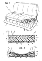
- Figure 1 is a general perspective view (partially cut away) of a seat according to the invention,
- Figures 2 and 3 are two median cross-sections of the squab of Figure 1, taken on the line II-II of that Figure, which show the seat in question in the undeformed rest position and in the deformed position which it assumes under the weight of a seated person, respectively, and
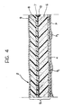
- Figure 4 is a further cross-section, substantially corresponding to Figure 2, reproduced on a slightly enlarged scale, showing a possible alternative embodiment of the invention.
- In the drawings, a seat, generally indicated 1, is intended to be fitted in the passenger compartment of a motor vehicle, such as a motor car (not illustrated as a whole). More precisely, this is concerned with a rear (bench) seat fitted on a raised portion of the floor P of the passenger compartment of the motor car, provided with stiffening ribs P₁.
- The seat 1 as a whole has a seat portion (or, in short, a "squab") 2 and a vertical portion or
backrest 3 which extends upwards from the rear portion of thesquab 2. - Naturally, the terms "front" and "rear" and "lower" and "upper" as used in this specification relate to the normal position of mounting of the seat 1 in the passenger compartment of the motor vehicle, with respect to the normal direction of travel of the latter.
- Both the
squab 2 and the backrest 3 (or possibly just one of them, preferably the squab 2) is constituted essentially by a structure or "body" 4 of rigid or semirigid material (for example, moulded plastics or metal) which is intended to rest on the floor P (or on a support structure projecting therefrom) and carries an applied mass ofpadding 5 with a layered structure. - Proceeding from the base region (in contact with the body 4) towards the upper region (that is, the "outer" region intended to face the body of the person occupying the seat) one can identify in the layered mass 5:
- a soft, resilient lower orbase layer 6,
- a relatively inelastic intermediate layer 7 with some degree of plastic memory, and
- a soft upper or "outer"layer 8. - With regard to the meaning of the term "relatively inelastic with some degree of plastic memory" in relation to the intermediate layer 7, reference should be made to the terminological statement made in the introduction to the present description.
- As far as the selection of the materials which form the three
layers 6, 7 and 8 (which are not shown to scale in Figures 2 and 3 for clarity of illustration) is concerned, various possibilities can be proposed on the basis of experimental findings. - For example, a material such as the expanded polyurethane foam sold under the trade name PURFOAM (produced by Padana Plastici) may be used for the production of the
base layer 6. - The selection of a thickness of the order of from approximately 5 to approximately 7.1 cm has proved particularly effective for the
layer 6. - With regard to the intermediate layer 7, however, it has proved possible to use the polyethylene foam sold under the trade name ETAFOAM (produced by Dow Chemical).
- This material has a generally elastoplastic behaviour which means that it tends to retain the deformed condition assumed as a result of a stress and return to its original undeformed condition only after the stress has ceased for a certain period of time. In the embodiments which have proved most effective up to now, this period has a duration of from about 0.1 to about 1 second, preferably around the upper end of this range. For the layer 7 made of this material, the selection of a thickness within the range of about 0.5 to about 1.5 cm has proved particularly effective, at least for the region supporting a person seated on a normal motor vehicle seat.
- Finally, as far the soft
upper layer 8 is concerned, it is possible, for example, to use a material substantially identical to the material constituting thelayer 6, preferably with a selected thickness of the order of from about 1 to about 1.5 cm which brings the overall thickness of thelayered mass 5 to a value of the order of 6-10 cm. - The top or
outer layer 8 may be covered by a protective layer 9 made, for example, from fabric (possibly padded), synthetic material (for example, vinyl leather or the like) or even from a layer of natural leather. - As a possible alternative, the protective layer 9 may be constituted by an upper portion of the layer 8 (which, as has been seen, is usually a foamed or sponge material) which has been subjected - according to known criteria - to a condensation treatment intended to provide it with a more compact structure suitable for carrying out the function of a protective layer.
- A comparison of Figures 2 and 3 shows that the upper or
outer layer 8 is almost completely deformed by a person M occupying the seat, so that it lies on the intermediate layer 7. The latter consequently assumes a general bowl shape which is adapted in a complementary manner to the anthropometric characteristics of the person M, so as to achieve the required restraint. This all occurs without causing the complete deformation of thebase layer 6 which therefore retains its capacity for further deformation as a result of incidental stresses such as those resulting from bumps, etc... - The above description of the
squab 2 can supply equally well to thebackrest 3, in which thebase layer 6 and theouter layer 8 are situated behind and in front of the intermediate layer 7, respectively. - The alternative embodiment shown in Figure 4 provides for tee use of an
additional fabric layer 10, which is fairly rigid, applied (for instance by glueing) on the upper or the lower surface of the intermediate layer 7. - As already seen, under the action of the weight of the person occupying the seat, the intermediate layer 7 is flexed and the load is distributed over a larger surface than that represented by the body structures contacting the squab.
- The
fabric layer 10 is useful in obtaining a still larger surface, involving a larger portion of the squab in the springing action. - Thus, the insertion of the
fabric layer 10, which is by itself substantially unextendible, ensures the following advantages:
- a wider distribution of the load on the squab surface;
- minimum weight increase;
- reduced costs and, in any case, costs which are lower than possible alternatives;
- synergism (i.e. mutual increase) of the desired effect, in contact between the plastic layer 7 and thefabric layer 10; and
- no appreciable increase in thickness. - If the
fabric layer 10 is applied (as shown in Figure 4) under the plastic layer 7, then this latter operates under compression stress. - If, on the contrary, the
fabric 10 is applied over the plastic layer 7, then this latter operates under traction stress. - Both solutions are viable since, as demonstrated by the tests effected, adhesion between the plastic layer 7 and the
fabric 10 is extremely effective also when using traditional adhesives used for glueing different layers of foamed materials.
Claims (17)
- a soft, resilient base layer (6),
- a relatively inelastic intermediate layer (7) with some degree of plastic memory, and
- a soft outer layer (8).
Applications Claiming Priority (2)
| Application Number | Priority Date | Filing Date | Title |
|---|---|---|---|
| IT8867887A IT1224463B (en) | 1988-10-03 | 1988-10-03 | Motor vehicle seat with layered construction |
| IT6788788 | 1988-10-03 |
Publications (2)
| Publication Number | Publication Date |
|---|---|
| EP0363330A1 true EP0363330A1 (en) | 1990-04-11 |
| EP0363330B1 EP0363330B1 (en) | 1994-02-16 |
Family
ID=11306094
Family Applications (1)
| Application Number | Title | Priority Date | Filing Date |
|---|---|---|---|
| EP89830387A Expired - Lifetime EP0363330B1 (en) | 1988-10-03 | 1989-09-12 | A seat with a layered structure, particularly for motor vehicles |
Country Status (4)
| Country | Link |
|---|---|
| EP (1) | EP0363330B1 (en) |
| DE (1) | DE68913122T2 (en) |
| ES (1) | ES2049350T3 (en) |
| IT (1) | IT1224463B (en) |
Cited By (3)
| Publication number | Priority date | Publication date | Assignee | Title |
|---|---|---|---|---|
| EP0562453A1 (en) * | 1992-03-24 | 1993-09-29 | FIAT AUTO S.p.A. | A seat squab, for example, for motor-vehicle seats |
| US5551756A (en) * | 1994-03-16 | 1996-09-03 | Custom Orthotics, Inc. | Orthotic wheelchair positioning device and support system |
| FR2885614A1 (en) * | 2005-05-13 | 2006-11-17 | Arconnerie Soc Par Actions Sim | Equitation saddle`s pommel, has outer layers oriented such that their respective fibers are parallel and perpendicular to median geometrical plane, and inner layers oriented such that their respective fibers are oriented at specific degrees |
Families Citing this family (2)
| Publication number | Priority date | Publication date | Assignee | Title |
|---|---|---|---|---|
| DE10249871A1 (en) * | 2002-10-25 | 2004-05-06 | Delphi Technologies, Inc., Troy | Device for detecting seat occupancy |
| DE102008045859A1 (en) * | 2007-09-07 | 2009-03-12 | Volkswagen Ag | Shape-changeable vehicle seat for e.g. child seat arrangement, has core implemented as bodies that form contour in installation position with frame for accommodating passenger and protrude from contour in other position for configuring seat |
Citations (3)
| Publication number | Priority date | Publication date | Assignee | Title |
|---|---|---|---|---|
| US3047888A (en) * | 1960-12-05 | 1962-08-07 | George O Shecter | Cushioning structure |
| US3118153A (en) * | 1960-10-21 | 1964-01-21 | Davidson Rubber Company Inc | Upholstery corner construction |
| US3833259A (en) * | 1972-05-30 | 1974-09-03 | Deere & Co | Vehicle seat comprising three foam layers |
-
1988
- 1988-10-03 IT IT8867887A patent/IT1224463B/en active
-
1989
- 1989-09-12 DE DE68913122T patent/DE68913122T2/en not_active Expired - Lifetime
- 1989-09-12 EP EP89830387A patent/EP0363330B1/en not_active Expired - Lifetime
- 1989-09-12 ES ES89830387T patent/ES2049350T3/en not_active Expired - Lifetime
Patent Citations (3)
| Publication number | Priority date | Publication date | Assignee | Title |
|---|---|---|---|---|
| US3118153A (en) * | 1960-10-21 | 1964-01-21 | Davidson Rubber Company Inc | Upholstery corner construction |
| US3047888A (en) * | 1960-12-05 | 1962-08-07 | George O Shecter | Cushioning structure |
| US3833259A (en) * | 1972-05-30 | 1974-09-03 | Deere & Co | Vehicle seat comprising three foam layers |
Cited By (3)
| Publication number | Priority date | Publication date | Assignee | Title |
|---|---|---|---|---|
| EP0562453A1 (en) * | 1992-03-24 | 1993-09-29 | FIAT AUTO S.p.A. | A seat squab, for example, for motor-vehicle seats |
| US5551756A (en) * | 1994-03-16 | 1996-09-03 | Custom Orthotics, Inc. | Orthotic wheelchair positioning device and support system |
| FR2885614A1 (en) * | 2005-05-13 | 2006-11-17 | Arconnerie Soc Par Actions Sim | Equitation saddle`s pommel, has outer layers oriented such that their respective fibers are parallel and perpendicular to median geometrical plane, and inner layers oriented such that their respective fibers are oriented at specific degrees |
Also Published As
| Publication number | Publication date |
|---|---|
| DE68913122T2 (en) | 1994-05-26 |
| DE68913122D1 (en) | 1994-03-24 |
| ES2049350T3 (en) | 1994-04-16 |
| EP0363330B1 (en) | 1994-02-16 |
| IT8867887A0 (en) | 1988-10-03 |
| IT1224463B (en) | 1990-10-04 |
Similar Documents
| Publication | Publication Date | Title |
|---|---|---|
| US3758159A (en) | Vehicle seat construction | |
| US5462339A (en) | Sitting section of a vehicle seat | |
| JPH056824Y2 (en) | ||
| US6231125B1 (en) | Seat with resilient sheet-formed seat cushion | |
| CA2135664C (en) | Seat cushion assembly | |
| US9266455B2 (en) | Cushion pad for car seat | |
| US3049730A (en) | Seat structure | |
| US3844614A (en) | Seat cushion | |
| US4761035A (en) | Seat cushion assembly | |
| US11603155B2 (en) | Bicycle saddle, saddle pad, and method for producing a bicycle saddle or saddle pad | |
| EP0407361B1 (en) | A seat backrest with a layered structure | |
| US3697133A (en) | Seat back structure | |
| EP0363330B1 (en) | A seat with a layered structure, particularly for motor vehicles | |
| JPH0132912Y2 (en) | ||
| EP0467123B1 (en) | A layered support structure for seats, particularly for the squabs of motorvehicle seats, and a method for its manufacture | |
| JP5529560B2 (en) | Seat pad and seat | |
| CZ263094A3 (en) | Seat upholstering and process for producing seat cushion with said upholstering | |
| JPH038119Y2 (en) | ||
| JPH0515795Y2 (en) | ||
| EP0562453A1 (en) | A seat squab, for example, for motor-vehicle seats | |
| JPH0537805Y2 (en) | ||
| CN220483142U (en) | Vehicle seat and vehicle | |
| CN215042293U (en) | Antibacterial anti-mite anti-seepage automobile seat cover | |
| EP0566065B1 (en) | Seat padding, for example, for vehicle seats | |
| JPS61234806A (en) | Composite cushion body |
Legal Events
| Date | Code | Title | Description |
|---|---|---|---|
| PUAI | Public reference made under article 153(3) epc to a published international application that has entered the european phase |
Free format text: ORIGINAL CODE: 0009012 |
|
| AK | Designated contracting states |
Kind code of ref document: A1 Designated state(s): DE ES FR GB IT SE |
|
| 17P | Request for examination filed |
Effective date: 19900711 |
|
| 17Q | First examination report despatched |
Effective date: 19911212 |
|
| GRAA | (expected) grant |
Free format text: ORIGINAL CODE: 0009210 |
|
| AK | Designated contracting states |
Kind code of ref document: B1 Designated state(s): DE ES FR GB IT SE |
|
| ITF | It: translation for a ep patent filed |
Owner name: JACOBACCI CASETTA & PERANI S.P.A. |
|
| REF | Corresponds to: |
Ref document number: 68913122 Country of ref document: DE Date of ref document: 19940324 |
|
| REG | Reference to a national code |
Ref country code: ES Ref legal event code: FG2A Ref document number: 2049350 Country of ref document: ES Kind code of ref document: T3 |
|
| ET | Fr: translation filed | ||
| PG25 | Lapsed in a contracting state [announced via postgrant information from national office to epo] |
Ref country code: GB Effective date: 19940912 |
|
| PG25 | Lapsed in a contracting state [announced via postgrant information from national office to epo] |
Ref country code: SE Effective date: 19940913 Ref country code: ES Free format text: LAPSE BECAUSE OF EXPIRATION OF PROTECTION Effective date: 19940913 |
|
| PLBE | No opposition filed within time limit |
Free format text: ORIGINAL CODE: 0009261 |
|
| STAA | Information on the status of an ep patent application or granted ep patent |
Free format text: STATUS: NO OPPOSITION FILED WITHIN TIME LIMIT |
|
| EAL | Se: european patent in force in sweden |
Ref document number: 89830387.0 |
|
| 26N | No opposition filed | ||
| GBPC | Gb: european patent ceased through non-payment of renewal fee |
Effective date: 19940912 |
|
| PG25 | Lapsed in a contracting state [announced via postgrant information from national office to epo] |
Ref country code: DE Effective date: 19950601 |
|
| EUG | Se: european patent has lapsed |
Ref document number: 89830387.0 |
|
| REG | Reference to a national code |
Ref country code: ES Ref legal event code: FD2A Effective date: 19990601 |
|
| PGFP | Annual fee paid to national office [announced via postgrant information from national office to epo] |
Ref country code: FR Payment date: 20010928 Year of fee payment: 13 |
|
| PG25 | Lapsed in a contracting state [announced via postgrant information from national office to epo] |
Ref country code: FR Free format text: LAPSE BECAUSE OF NON-PAYMENT OF DUE FEES Effective date: 20030603 |
|
| REG | Reference to a national code |
Ref country code: FR Ref legal event code: ST |
|
| PG25 | Lapsed in a contracting state [announced via postgrant information from national office to epo] |
Ref country code: IT Free format text: LAPSE BECAUSE OF NON-PAYMENT OF DUE FEES;WARNING: LAPSES OF ITALIAN PATENTS WITH EFFECTIVE DATE BEFORE 2007 MAY HAVE OCCURRED AT ANY TIME BEFORE 2007. THE CORRECT EFFECTIVE DATE MAY BE DIFFERENT FROM THE ONE RECORDED. Effective date: 20050912 |